Embed Size (px)
Citation preview
1
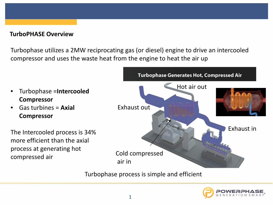
Turbophase utilizes a 2MW reciprocating gas (or diesel) engine to drive an intercooled compressor and uses the waste heat from the engine to heat the air up
Turbophase process is simple and efficient
• Turbophase =Intercooled
Compressor • Gas turbines = Axial Compressor
The Intercooled process is 34% more efficient than the axial process at generating hot compressed air
Exhaust in
Exhaust out
Cold compressed air in
Hot air out
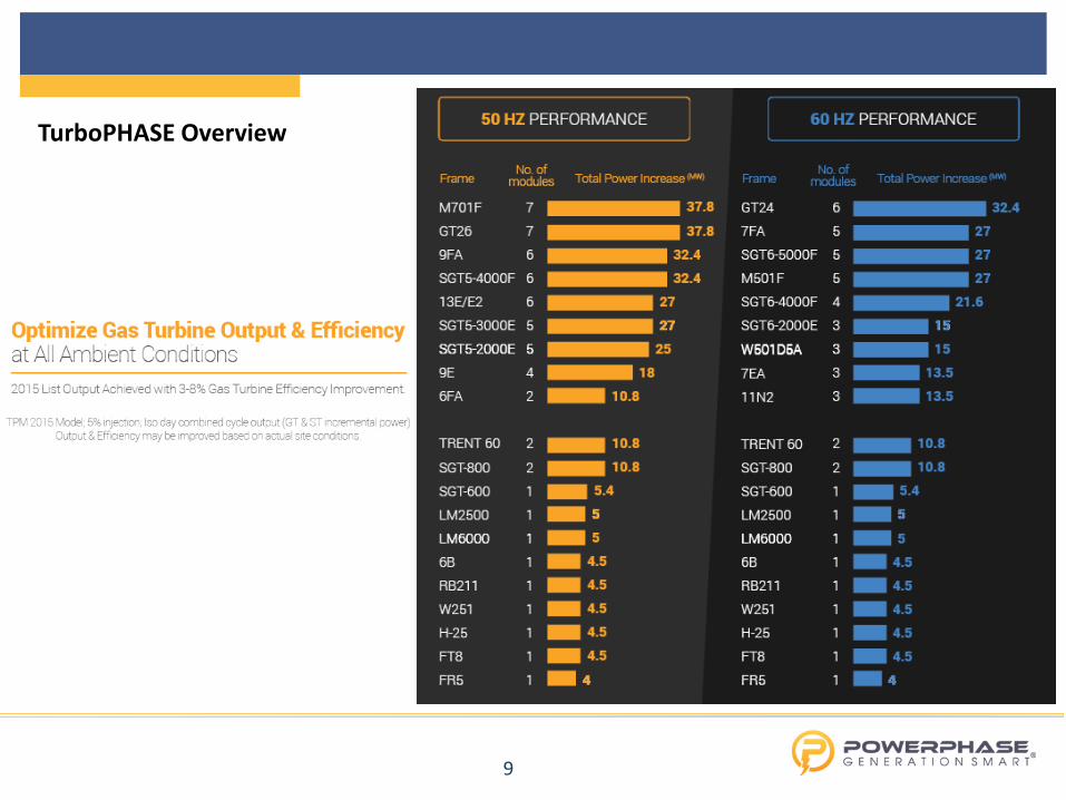
TurboPHASE Overview
2
TurboPHASE Overview
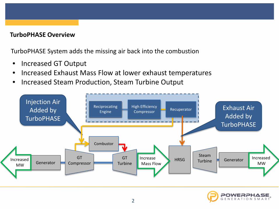
• Increased GT Output • Increased Exhaust Mass Flow at lower exhaust temperatures • Increased Steam Production, Steam Turbine Output
Generator Generator GT Compressor
GT Turbine
Combustor
Steam Turbine HRSG
Injection Air Added by
TurboPHASE
Reciprocating Engine
High Efficiency Compressor Recuperator
Reciprocating Engine
High Efficiency Compressor
Increased MW
Increased MW
Increase Mass Flow
Exhaust Air Added by
TurboPHASE
TurboPHASE System adds the missing air back into the combustion
3
TurboPHASE Overview
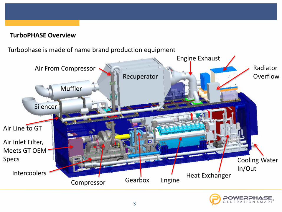
Recuperator Radiator Overflow
Muffler
Air Line to GT
Intercoolers Compressor Gearbox Engine
Heat Exchanger
Engine Exhaust Air From Compressor
Cooling Water In/Out
Silencer
Air Inlet Filter, Meets GT OEM Specs
Turbophase is made of name brand production equipment
4
TurboPHASE Overview
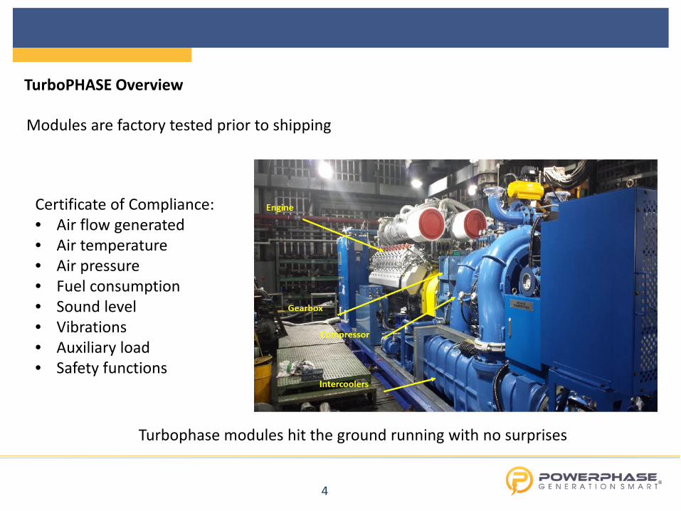
Modules are factory tested prior to shipping
Certificate of Compliance: • Air flow generated • Air temperature • Air pressure • Fuel consumption • Sound level • Vibrations • Auxiliary load • Safety functions
Turbophase modules hit the ground running with no surprises
5
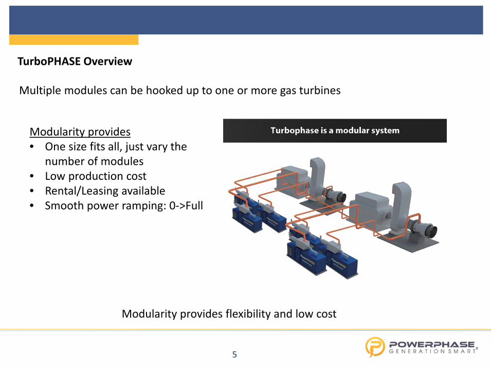
TurboPHASE Overview
Multiple modules can be hooked up to one or more gas turbines
Modularity provides • One size fits all, just vary the
number of modules • Low production cost • Rental/Leasing available • Smooth power ramping: 0->Full
Modularity provides flexibility and low cost
6
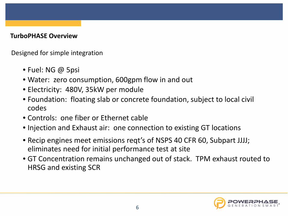
TurboPHASE Overview
Designed for simple integration Interconnects
• Fuel: NG @ 5psi • Water: zero consumption, 600gpm flow in and out • Electricity: 480V, 35kW per module • Foundation: floating slab or concrete foundation, subject to local civil
codes • Controls: one fiber or Ethernet cable • Injection and Exhaust air: one connection to existing GT locations • Recip engines meet emissions reqt’s of NSPS 40 CFR 60, Subpart JJJJ;
eliminates need for initial performance test at site • GT Concentration remains unchanged out of stack. TPM exhaust routed to
HRSG and existing SCR
7
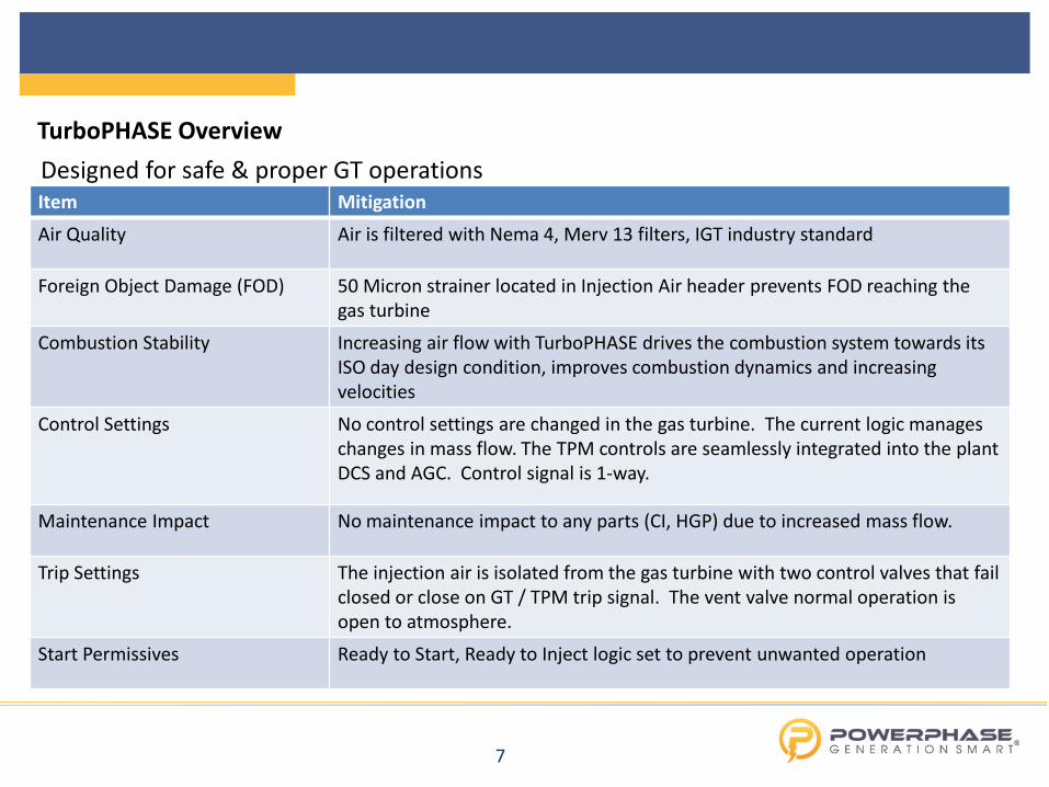
TurboPHASE Overview Designed for safe & proper GT operations Item Mitigation
Air Quality Air is filtered with Nema 4, Merv 13 filters, IGT industry standard
Foreign Object Damage (FOD) 50 Micron strainer located in Injection Air header prevents FOD reaching the gas turbine
Combustion Stability Increasing air flow with TurboPHASE drives the combustion system towards its ISO day design condition, improves combustion dynamics and increasing velocities
Control Settings No control settings are changed in the gas turbine. The current logic manages changes in mass flow. The TPM controls are seamlessly integrated into the plant DCS and AGC. Control signal is 1-way.
Maintenance Impact No maintenance impact to any parts (CI, HGP) due to increased mass flow.
Trip Settings The injection air is isolated from the gas turbine with two control valves that fail closed or close on GT / TPM trip signal. The vent valve normal operation is open to atmosphere.
Start Permissives Ready to Start, Ready to Inject logic set to prevent unwanted operation
8
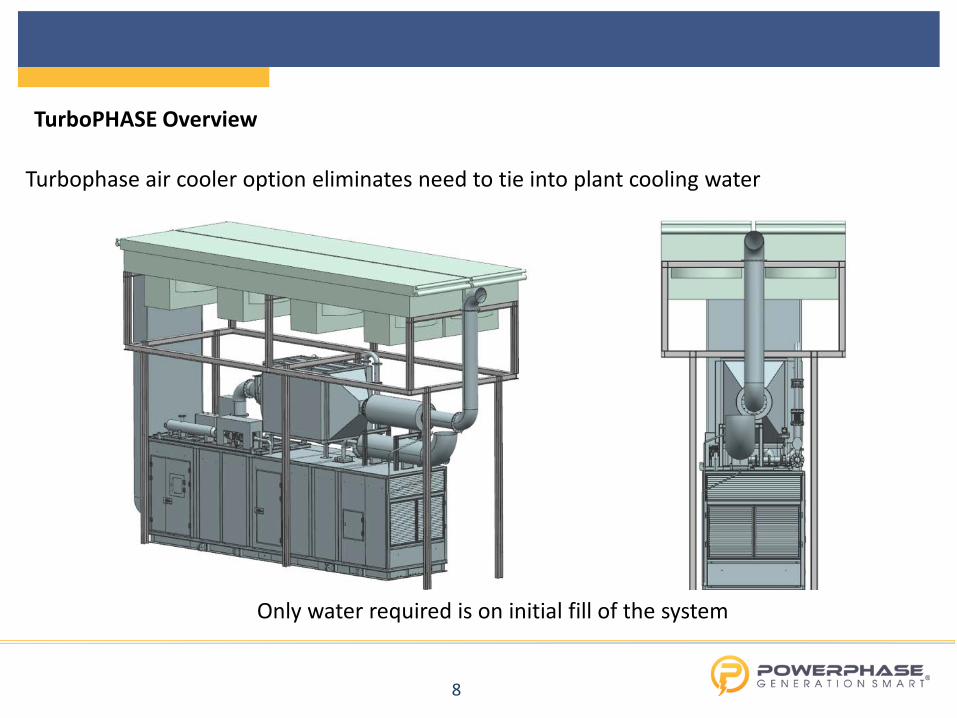
TurboPHASE Overview
Turbophase air cooler option eliminates need to tie into plant cooling water
Only water required is on initial fill of the system
9
TurboPHASE Overview
10
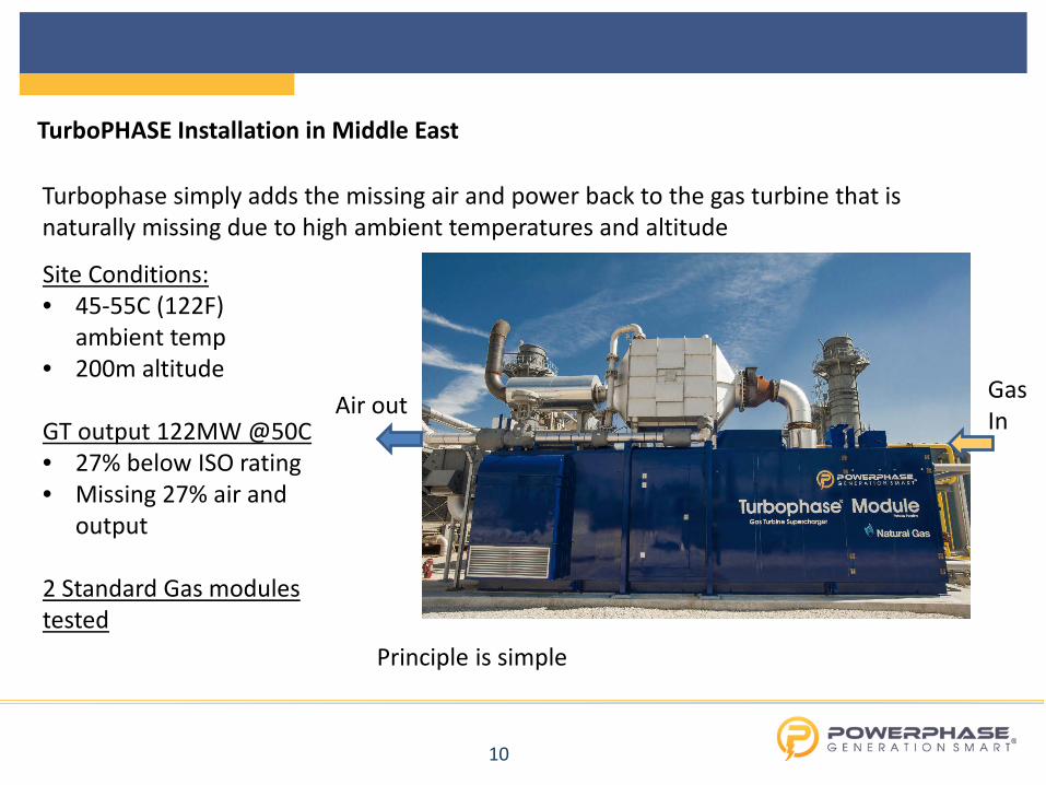
TurboPHASE Installation in Middle East
Turbophase simply adds the missing air and power back to the gas turbine that is naturally missing due to high ambient temperatures and altitude
Site Conditions: • 45-55C (122F)
ambient temp • 200m altitude GT output 122MW @50C • 27% below ISO rating • Missing 27% air and
output
2 Standard Gas modules tested
Air out Gas In
Principle is simple
11
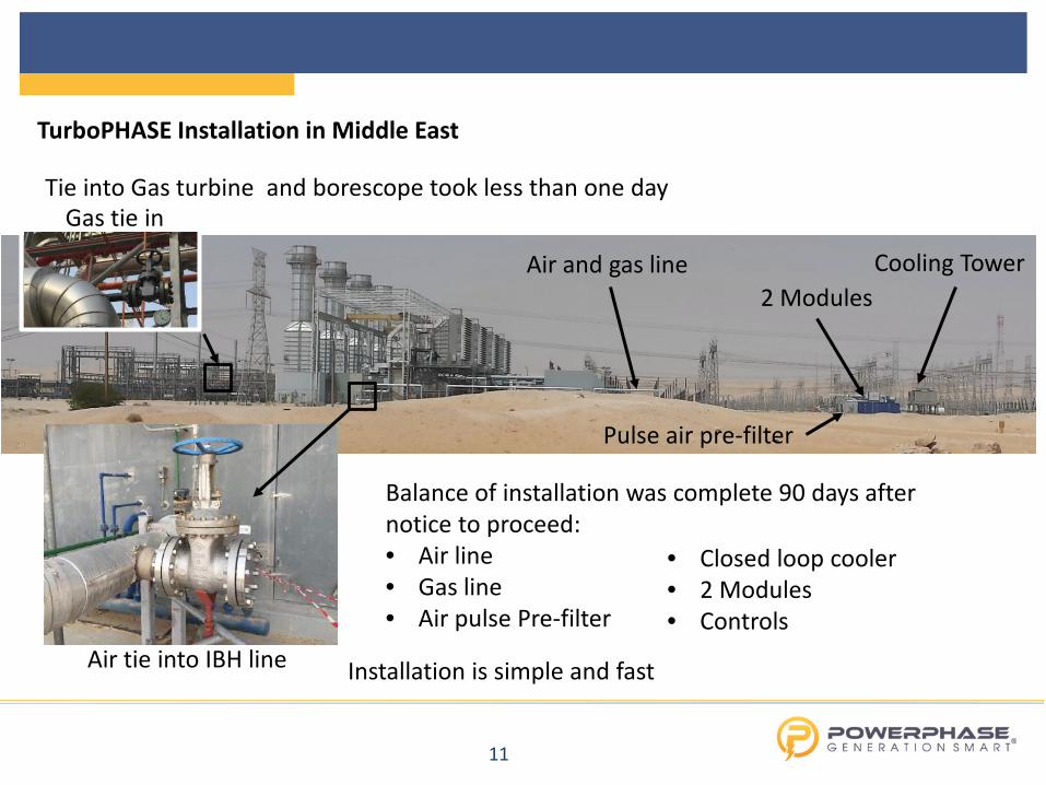
Tie into Gas turbine and borescope took less than one day
Balance of installation was complete 90 days after notice to proceed: • Air line • Gas line • Air pulse Pre-filter
Installation is simple and fast
• Closed loop cooler • 2 Modules • Controls
2 Modules Cooling Tower Air and gas line
Air tie into IBH line
Gas tie in
Pulse air pre-filter
TurboPHASE Installation in Middle East
12
TurboPHASE Installation in Middle East
Every time units are turned on/off, incremental MW and fuel was measured (every day) 1. Net Power of GT existing customer MW meter 2. Auxiliary load validated by customer (35kw per module, 50 kW pumps, 75 kW fans,
185 total for the two modules) 3. GT Fuel existing customer meter 4. TPM Fuel new meter 5. Net Power = 1-2 6. Net Plant heat rate = (3+4)/(1-2)
Turbophase demonstrated power output, efficiency, part load, and life extension
Turbophase is an extremely flexible system and very simple to measure the performance
• Demonstrated Base and part load fuel efficiency with air injection • Demonstrated Base Load output with parts life extension 24,000 hrs to 32,000 hrs
13
TurboPHASE Installation in Middle East
115
120
125
130
135
140
145
90 95 100 105 110 115 120 125
GT O
utpu
t (M
W)
GT Inlet Temperature (deg F)
No injection 1 TPM injecting 2 TPM injectingLinear (No injection) Linear (1 TPM injecting) Linear (2 TPM injecting)
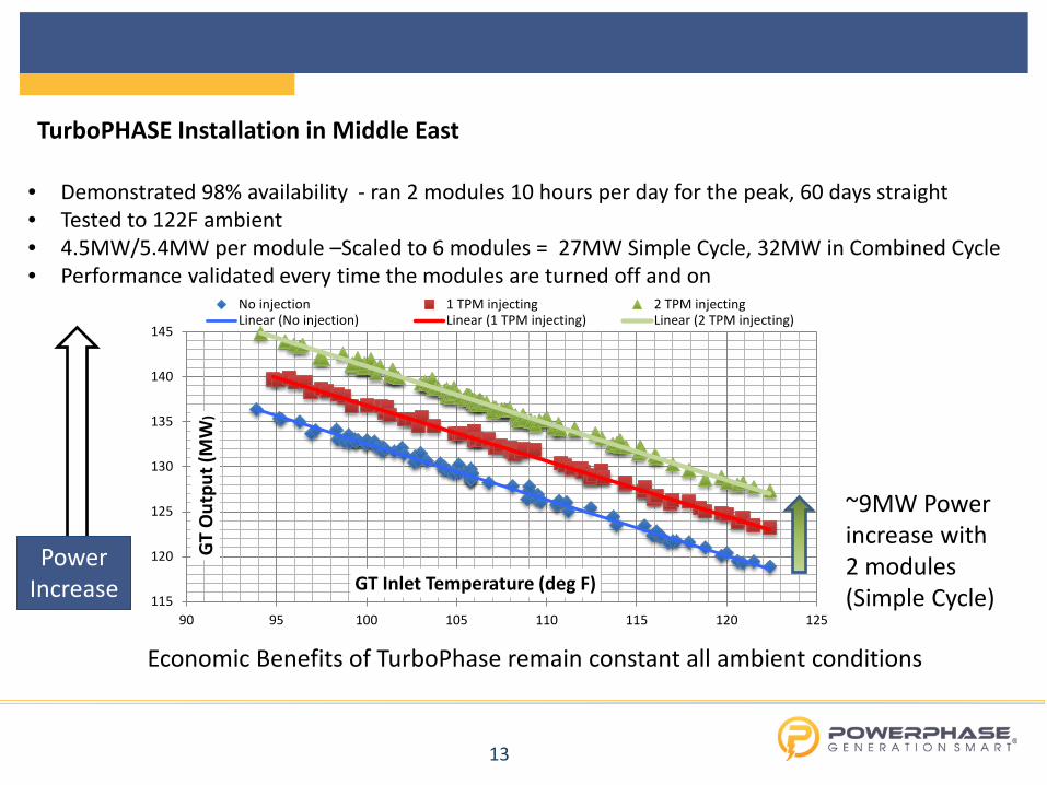
• Demonstrated 98% availability - ran 2 modules 10 hours per day for the peak, 60 days straight • Tested to 122F ambient • 4.5MW/5.4MW per module –Scaled to 6 modules = 27MW Simple Cycle, 32MW in Combined Cycle • Performance validated every time the modules are turned off and on
Economic Benefits of TurboPhase remain constant all ambient conditions
Power Increase
~9MW Power increase with 2 modules (Simple Cycle)
14
TurboPHASE Installation in Middle East
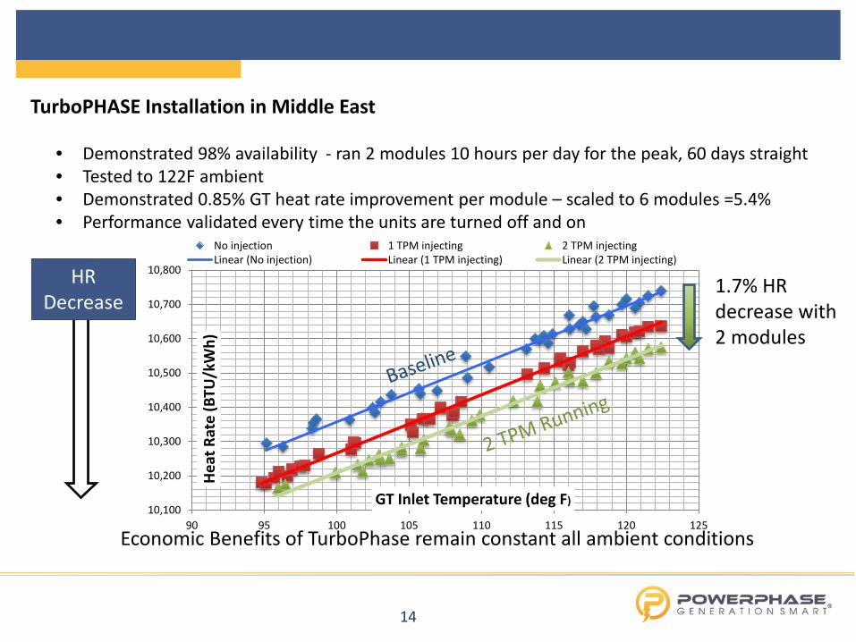
• Demonstrated 98% availability - ran 2 modules 10 hours per day for the peak, 60 days straight • Tested to 122F ambient • Demonstrated 0.85% GT heat rate improvement per module – scaled to 6 modules =5.4% • Performance validated every time the units are turned off and on
Economic Benefits of TurboPhase remain constant all ambient conditions
HR Decrease
10,100
10,200
10,300
10,400
10,500
10,600
10,700
10,800
90 95 100 105 110 115 120 125
Heat
Rat
e (B
TU/k
Wh)
GT Inlet Temperature (deg F)
No injection 1 TPM injecting 2 TPM injectingLinear (No injection) Linear (1 TPM injecting) Linear (2 TPM injecting)
1.7% HR decrease with 2 modules
15
TurboPHASE Installation in Middle East
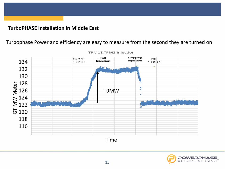
Turbophase Power and efficiency are easy to measure from the second they are turned on
TPM1&TPM2 Injection
Start ofInjection
FullInjection
NoInjection
StoppingInjection
+9MW
Time
GT M
W M
eter
134 132 130 128 126 124 122 120 118 116
16
TurboPHASE Installation in United States
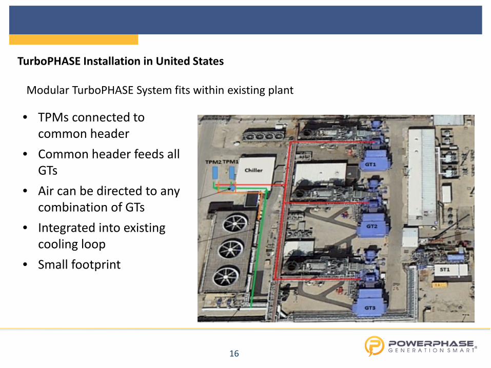
• TPMs connected to common header
• Common header feeds all GTs
• Air can be directed to any combination of GTs
• Integrated into existing cooling loop
• Small footprint
Modular TurboPHASE System fits within existing plant

17
TurboPHASE Installation in United States
• New Tee welded into existing line
• Connected to existing IBH line
• External to enclosure • Injection control valve
bolted to Tee flange • TPMs located 500+ ft
away from injection flange
Integrated to existing turbines without outage
18
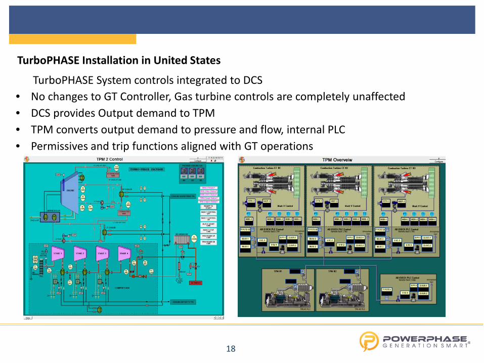
TurboPHASE Installation in United States
TurboPHASE System controls integrated to DCS • No changes to GT Controller, Gas turbine controls are completely unaffected • DCS provides Output demand to TPM • TPM converts output demand to pressure and flow, internal PLC • Permissives and trip functions aligned with GT operations
19
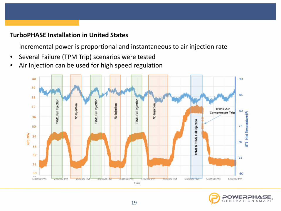
TurboPHASE Installation in United States
Incremental power is proportional and instantaneous to air injection rate • Several Failure (TPM Trip) scenarios were tested • Air Injection can be used for high speed regulation
20
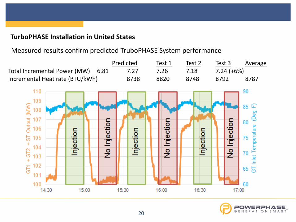
TurboPHASE Installation in United States
Measured results confirm predicted TruboPHASE System performance Predicted Test 1 Test 2 Test 3 Average Total Incremental Power (MW) 6.81 7.27 7.26 7.18 7.24 (+6%) Incremental Heat rate (BTU/kWh) 8738 8820 8748 8792 8787
21
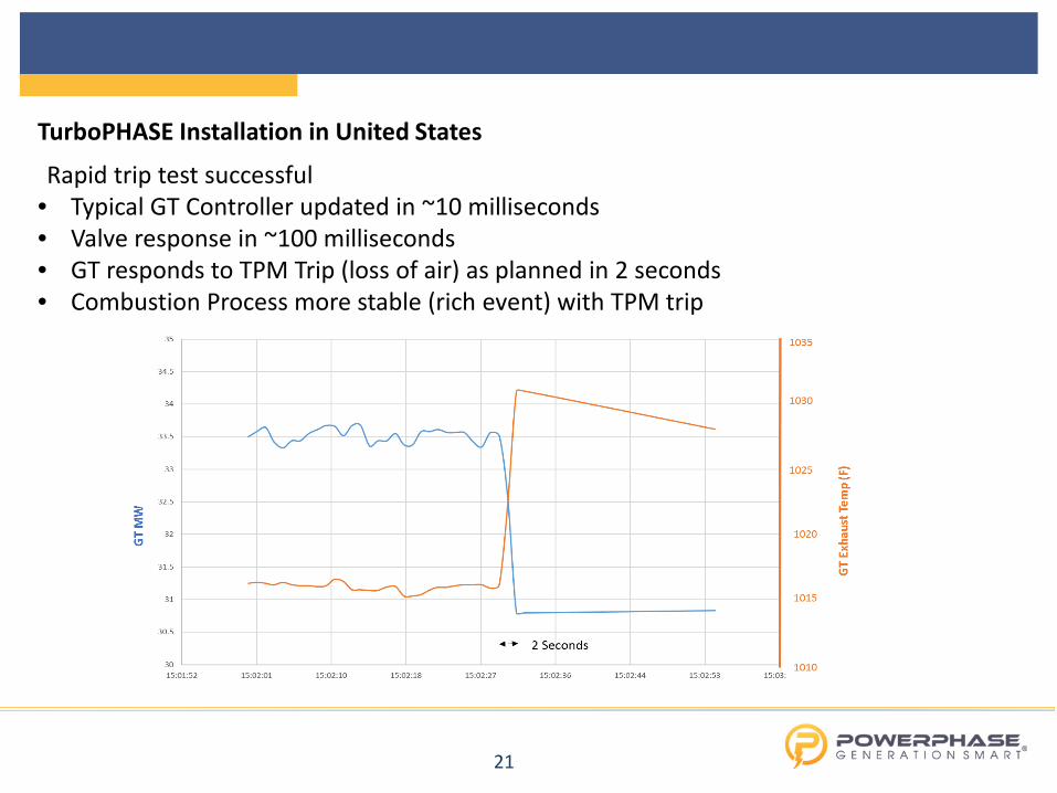
TurboPHASE Installation in United States
Rapid trip test successful • Typical GT Controller updated in ~10 milliseconds • Valve response in ~100 milliseconds • GT responds to TPM Trip (loss of air) as planned in 2 seconds • Combustion Process more stable (rich event) with TPM trip
22
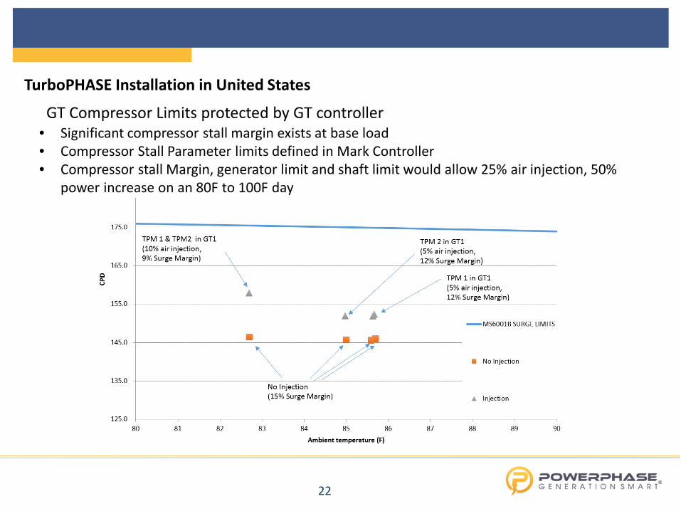
TurboPHASE Installation in United States
GT Compressor Limits protected by GT controller • Significant compressor stall margin exists at base load • Compressor Stall Parameter limits defined in Mark Controller • Compressor stall Margin, generator limit and shaft limit would allow 25% air injection, 50%
power increase on an 80F to 100F day

23
Customers should contact: Steve Quisenberry Vice President (USA) +1 561 339 2096 [email protected] www.powerphasellc.com