Embed Size (px)
Citation preview
The Following is a Preview of
Understanding Rack PDUs with Ease
The Intelligent Power Distribution Unit (iPDU) Handbook is the definitive guide to rack PDUs and understanding how they can change the face of your data center. Written with the rack PDU novice in mind, this simple but elegant illustrated guide will cover the fundamental prin-ciples of powering your IT equipment using single or three-phase power while leveraging the advanced capabilities of different rack PDU models in order to increase uptime and availability while improving power efficiency.
The Full Book is Available for Purchase on Amazon.com www.amazon.com/iPDU-Handbook-Definitive-Guide-Distribution-ebook/dp/B00ZB3IKR6/
Would You Like to Download a Full FREE Copy of this title? Learn how at www.raritan.com/PDUhandbook

32.0 Fundamentals and Principles
2.0 Fundamentals and Principles
4 The iPDU Handbook
2.0 Fundamentals and Principles
2.1 Overview and Class of Devices
2.2 Electrical Terminology
2.3 Electrical Power Distribution to the Rack
2.4 Plugs, Outlets, and Cords
2.5 Ratings and Safety
2.6 Overload Protection
52.0 Fundamentals and Principles
IT
equipment is normally mounted in racks or cabinets with provisions for all necessary cables, ventilation, cooling and convenient access. There are large data center PDUs that are used earlier in the power chain and take the form of panel boards mounted on walls or free standing pedestals. In this handbook
we’re discussing only the rack PDU, at the end of the chain, which supplies power to the IT equipment in the rack. Unless otherwise stated any reference to “PDU” for the remainder of this handbook means “rack PDU.”
Rack PDUs come in many configurations with respect to number and type of receptacles, voltage, load capacity and physical mounting (horizontal or vertical). A unit may perform no function other than providing power to the devices plugged into it; or it may also provide additional functions—for example, turning power off and on remotely, monitoring power consumption and sensing the temperature in an IT equipment rack.
2.1 Overview and Class of Devices
A rack PDU is mounted in an IT equipment rack and provides electrical power to various IT devices such as servers, networking, and storage equipment. Today, rack PDUs are available in a number of configurations. We describe below the basic characteristics of four types of rack PDUs.
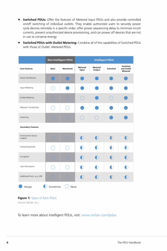
2.1.1 Types of Rack PDUs
Rack PDUs can be divided into two categories: Non-Intelligent PDUs and Intelligent PDUs
Non-Intelligent PDUs
f Basic PDUs: Are power strips that are used in critical environments such as data centers. They distribute correct voltage and current to multiple outlets to power IT equipment in racks.
f Monitored PDUs: Allow a user to view a local display that typically provides electric current information only. However, this information cannot be accessed remotely as the units have no network connectivity capabilities.
Intelligent PDUs
f Metered Input PDUs: Meter power at the PDU-level and can display the data both local-ly and over a network. Metering helps users to determine power usage and available capacity at the rack and facilitates provisioning. By metering at the input level, users can avoid overloading circuits and more easily calculate efficiency metrics like Power Usage Effectiveness (PUE).
f Metered Outlet PDUs: Meter power at the outlet-level and can display the data both locally and over a network. Like metered input PDUs, outlet-metered models help users to determine power usage and available capacity at the rack, and also facilitate provisioning. Most importantly, outlet-level metering allows users to understand power consumption at the device or server-level which makes it possible to allocate costs to specific business units or customers.
6 The iPDU Handbook
f Switched PDUs: Offer the features of Metered Input PDUs and also provide controlled on/off switching of individual outlets. They enable authorized users to securely power cycle devices remotely in a specific order, offer power sequencing delay to minimize inrush currents, prevent unauthorized device provisioning, and can power off devices that are not in use to conserve energy.
f Switched PDUs with Outlet Metering: Combine all of the capabilities of Switched PDUs with those of Outlet -Metered PDUs.
Figure 1: Types of Rack PDUs(Source: Raritan, Inc.)
To learn more about intelligent PDUs, visit: www.raritan.com/ipdus
Non-Intelligent PDUs Intelligent PDUs
Core Features Basic MonitoredMetered
InputMetered Output
SwitchedSwitched
and Outlet Metered
Power Distribution
Input Metering
Outlet Metering
Network Connectivity
Switching
Secondary Features
Environment Sensor Support
Strong Passwords
Encryption
User Permissions
Additional Ports, e.g. USB
Always Sometimes Never
72.0 Fundamentals and Principles
2.2 Electrical Terminology
It will be helpful to review several electrical term definitions before discussing rack PDUs in more detail.
Voltage (Volt): Electromotive force, or difference in electrical potential, measured in volts and equal to the current times the resistance.
Current (Amp): The flow or rate of flow of electrons, ions, or holes in a conductor or medium between two points having a difference in potential, measured in amperes and equal to the ratio of the voltage to the resistance.
Active power (Watt): The real power drawn by an IT device. This determines the actual power purchased from the utility company and the heat loading generated by the equipment since, for IT equipment, 1W of electricity equals 1W of heat.
Apparent power (VA): The product of the voltage applied to the IT device times the current drawn by the equipment. The VA rating is used for sizing wiring and circuit breakers. The apparent power is always equal to or larger than the active power.
Power factor: The ratio of active power to apparent power.
Energy measurement (kW): Electrical energy is measured at one instant in time in watts or kilowatts. For example, a 100W light bulb consumes 100 watts at any instant in time, but energy is consumed, and billed for by utilities, over time. A kilowatt-hour (kWh) is a unit of electrical energy or work, equal to the power supplied by one kilowatt for one hour, e.g. a 1000W light bulb left on for one hour, or a 100W light bulb left on for ten hours.
Line: An electrical conductor which is a source of voltage, e.g. 120V. In a single-phase system there are one or two lines. In a three-phase system there are three lines.
Neutral: An electrical conductor that provides a return path for the voltage supplied by a line. The neutral itself is not a source of voltage.
Ground: A conducting body, such as the earth or an object connected with the earth, whose potential is taken as zero and to which an electric circuit can be connected. The purpose of a ground wire is to safely direct stray currents to ground rather than allowing them to pass through someone contacting the stray currents.
4-wire and 5-wire systems: A 4-wire rack PDU consists of one ground wire and three lines (see Three phase Delta below), each line carrying equal voltage but each voltage sine wave is 120 degrees out of phase with the others. The voltage of two lines is available (line to line, e.g., L1-L2). A 5-wire system is the same as the 4-wire system but with the addition of a neutral wire (see Three phase Wye below) so that the voltage of one line can be supplied (line to neutral) as well as the voltage of two lines (line to line).
Three-phase Delta “∆“: This configuration gets the name Delta because a schematic drawing of it has three transformers forming a triangle or the Greek letter Delta. The three lines connect to the three “corners” of the triangle.
Three-phase Wye “Y“: This configuration gets the name Wye because a schematic draw-ing of it has three transformers meeting in the center forming the letter “Y”. The three lines connect to the three “branches” of the “Y” and the neutral connects to the center.
8 The iPDU Handbook
2.3 Electrical Power Distribution to the Rack
2.3.1 Branch Circuits
Power is distributed to the rack over one or more electrical branch circuits. Branch circuits are power feeds that originate from a panel, switch or distribution board and terminate into an electrical receptacle mounted in a junction box near the IT equipment rack. Depending on the data center’s layout, branch circuit wiring can be overhead, underneath a raised floor or both. The rack PDU itself could have multiple branch circuits. See Section 2.6 for details regarding branch circuit protection requirements.
2.3.2 Branch Circuit Load Capacity
The power that can be delivered by a branch circuit depends on the electrical characteristics of the circuit. A key factor in delivering power to a rack is whether the power is single phase or three phase. The amount of electricity delivered to a rack is often referred to as the load capacity and is the product of the rated voltage and the rated current and is presented as Volt-Amps (VA) or kVA (VA x 1000). Given the rated voltage and current, the load capacity that can be delivered by a branch circuit is determined using these formulas:
f Single phase: Load Capacity = Rated Voltage x Rated Current
f Three phase: Load Capacity = √3 x Rated Voltage x Rated Current
2.3.3 Branch Circuits: Rated Voltage
The rated voltage of a branch circuit specifies both its magnitude (volts) and number of phase conductors. Single-phase wiring is straight forward and consists of two wires (plus safety ground) where the AC voltage is a single sinusoidal wave as measured across the two wires.
Three-phase wiring is more complicated and consists of either three (three-phase conductors) or four (three-phase and one neutral) wires, plus safety ground. Three-phase branch circuits deliver more power, but require a rack PDU specially designed for three-phase branch circuits. Internally, a three-phase rack PDU divides the 3 or 4 branch circuit wires into pairs of single phase circuits – and these single-phase circuits are wired to the rack PDU’s single-phase outlet receptacles.
The three-phase conductors have the same voltage magnitude but the sinusoidal AC wave-forms are out of phase with each other by 120 degrees. Regardless of the number of wires, the rated voltage of three-phase wiring is always the measured voltage difference between any two-phase conductor wires – not the difference between a phase wire and neutral. Just as with single-phase power described above, connecting across one 120V hot line and the neutral provides 120V AC. Connecting across any two 120V hot lines, say L1 and L2, provides 208V AC, not 240V AC. Why? Because the phase of L1 is offset 120 degrees from L2 the volt-age is not 240V (120V x 2), as it is for single-phase, but is 120V x √3 or 120V x 1.732 = 208V. A three-phase PDU can deliver three circuits of 208V each. Some rack PDUs take advantage of a neutral wire to provide three circuits of both 120V and 208V. But as mentioned in the preceding paragraph, regardless of the number of wires, or whether or not both a higher and lower voltage are supplied as outputs, a three-phase rack PDU is rated at the voltage between two phases, e.g., L1 and L2 which in the example here is 208V.
92.0 Fundamentals and Principles
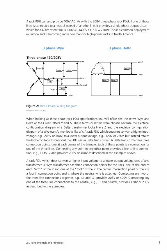
A rack PDU can also provide 400V AC. As with the 208V three-phase rack PDU, if one of those lines is connected to a neutral instead of another line, it provides a single-phase output circuit-- which for a 400V-rated PDU is 230V AC (400V / 1.732 = 230V). This is a common deployment in Europe and is becoming more common for high-power racks in North America.
Figure 2: Three-Phase Wiring Diagram(Source: Raritan, Inc.)
When looking at three-phase rack PDU specifications you will often see the terms Wye and Delta or the Greek letters Y and Δ. These terms or letters were chosen because the electrical configuration diagram of a Delta transformer looks like a Δ and the electrical configuration diagram of a Wye transformer looks like a Y. A rack PDU which does not convert a higher input voltage, e.g., 208V or 400V, to a lower output voltage, e.g., 120V or 230V, but instead retains the higher voltage throughout the PDU uses a Delta transformer. A Delta transformer has three connection points, one at each corner of the triangle. Each of these points is a connection for one of the three lines. Connecting any point to any other point provides a line-to-line connec-tion, e.g., L1 to L2 and provides 208V or 400V as described in the examples above.
A rack PDU which does convert a higher input voltage to a lower output voltage uses a Wye transformer. A Wye transformer has three connection points for the lines, one at the end of each “arm” of the Y and one at the “foot” of the Y. The center intersection point of the Y is a fourth connection point and is where the neutral wire is attached. Connecting any two of the three line connections together, e.g., L1 and L2, provides 208V or 400V. Connecting any one of the three line connections to the neutral, e.g., L1 and neutral, provides 120V or 230V as described in the examples.
10 The iPDU Handbook
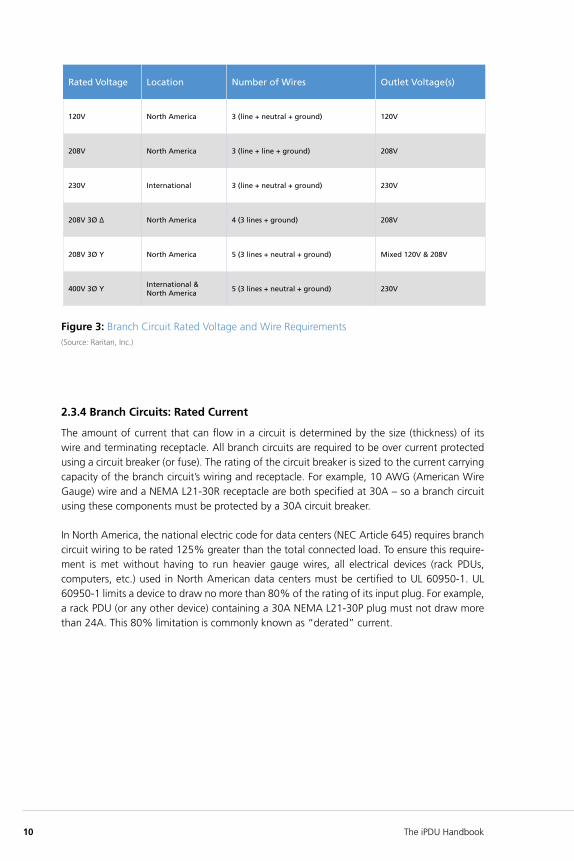
Figure 3: Branch Circuit Rated Voltage and Wire Requirements (Source: Raritan, Inc.)
2.3.4 Branch Circuits: Rated Current
The amount of current that can flow in a circuit is determined by the size (thickness) of its wire and terminating receptacle. All branch circuits are required to be over current protected using a circuit breaker (or fuse). The rating of the circuit breaker is sized to the current carrying capacity of the branch circuit’s wiring and receptacle. For example, 10 AWG (American Wire Gauge) wire and a NEMA L21-30R receptacle are both specified at 30A – so a branch circuit using these components must be protected by a 30A circuit breaker.
In North America, the national electric code for data centers (NEC Article 645) requires branch circuit wiring to be rated 125% greater than the total connected load. To ensure this require-ment is met without having to run heavier gauge wires, all electrical devices (rack PDUs, computers, etc.) used in North American data centers must be certified to UL 60950-1. UL 60950-1 limits a device to draw no more than 80% of the rating of its input plug. For example, a rack PDU (or any other device) containing a 30A NEMA L21-30P plug must not draw more than 24A. This 80% limitation is commonly known as “derated” current.
Rated Voltage Location Number of Wires Outlet Voltage(s)
120V North America 3 (line + neutral + ground) 120V
208V North America 3 (line + line + ground) 208V
230V International 3 (line + neutral + ground) 230V
208V 3Ø ∆ North America 4 (3 lines + ground) 208V
208V 3Ø Y North America 5 (3 lines + neutral + ground) Mixed 120V & 208V
400V 3Ø YInternational & North America
5 (3 lines + neutral + ground) 230V
11
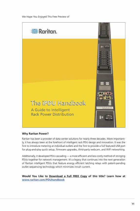
We Hope You Enjoyed This Free Preview of
Why Raritan Power?
Raritan has been a provider of data center solutions for nearly three decades. More important-ly, it has always been at the forefront of intelligent rack PDU design and innovation. It was the first to introduce metering at individual outlets and the first to provide a full featured USB port for plug-and-play quick setup, firmware upgrades, third-party webcam, and WiFi networking.
Additionally, it developed PDU cascading — a more efficient and less costly method of stringing PDUs together for network management. It’s a legacy that continues into the next generation of Raritan intelligent PDUs that feature energy efficient latching relays with patent-pending outlet sequencing technology which minimizes inrush current.
Would You Like to Download a Full FREE Copy of this title? Learn how at www.raritan.com/PDUhandbook

12 The iPDU Handbook
Raritan is a proven innovator of power management solutions, DCIM software, and KVM-over-IP for data centers of all sizes. Based in Somerset, NJ, Raritan has a global presence across 38 offices, serving 76 countries and 50,000 locations worldwide. Raritan’s award-winning hardware and software solutions increase energy efficiency, improve reliability, and raise productivity. For more information, please visit www.raritan.com or call 800-724-8090.
©2015 Raritan Inc. All rights reserved. Raritan®, Know more. Manage smarter.™ are registered trademarks or trademarks of Raritan Inc. or its wholly-owned subsidiaries. All others are registered trademarks or trademarks of their respective owners.
V1195


![NL20120205[1] - IPDU](https://img.pdfslide.us/doc/110x75/62e4a6191523861e0a7018f4/nl201202051-ipdu.jpg)

