Embed Size (px)
Citation preview

Medium VoltageYOUR ENERGY, OUR SYSTEMS, ANYWHERE

3
Introduction
ONE LEADER, TWO BRANDS
The world’s largest cable company, the Prysmian Group, consists of Prysmian and Draka which are two of the world’s most respected commercial brands in the industry. With subsidiaries in 50 countries, almost 100 manufacturing plants, 17 Research & Development Centres and around 22,000 employees, the Prysmian Group is truly a global company.
Proudly manufacturing in Australia since 1940, Prysmian understands local standards and conditions and our products are designed and developed accordingly. Prysmian specialises in integrated, added value cabling solutions highly customised to the individual specifications of customers. Prysmian operates a Quality Management System compliant with the requirements of ISO 9001:2008 and products are fully supported by the global technical and production capabilities of the Prysmian Group.
Prysmian understands local standards and conditions and our products are designed and developed accordingly.

4
THIS MANUAL CONTAINS TECHNICAL INFORMATION ON A WIDE VARIETY OF COMMONLY USED MEDIUM VOLTAGE (MV) POWER CABLES MANUFACTURED TO AUSTRALIAN STANDARD AS/NZS 1429.1.
Full constructional and technical details are given for Prysmian’s standard range of MV power cables. Other constructions and variants are available by special order.
For standard industrial applications, XLPE insulation is normally recommended, but for situations where the cable may be continuously subject to wet conditions, the well proven resistance of Prysmian’s EPR compound offers additional security. Both insulation systems have been assessed for long term resistance to water under the two year UNIPEDE test regime and successfully met the criteria. Prysmian’s EPR compound has also met the requirements of more onerous long term tests.
The standard oversheaths supplied are either BLACK PVC (5V-90) or a combination of layers of PVC and HDPE to AS/NZS 1429.1, AS/NZS 4026 and AS/NZS 3808. For situations where limiting the emission of smoke and corrosive gases from cables affected by fire is
desirable, the use of Prysmian’s LSOH HFS-90TP sheath to AS/NZS 3808 is recommended. These cables are constructionally and dimensionally the same as AS/NZS 1429.1 cables and employ the same insulation systems but with LSOH sheaths. The tabulated data in this technical manual is valid irrespective of the sheathing option.
High-density polyethylene sheath (HDPE) can be supplied where greater impermeability to moisture and greater resistance to abrasion is required for adverse installation conditions, but such sheaths are not recommended in areas of fire risk.
Where protection against termites and other invasive insects is required, cables can be supplied with a covering of Nylon 12, or with two helically applied brass or stainless steel tapes. Alternatively Prysmian offer Termitex™ covering as a protection against termites. For protection against rodents, Prysmian recommend the use of armour or steel tapes. Brass or copper tapes provide only limited protection against rodents and specifiers need to be aware of the risk for each installation.
Cable Components

5
Prysmian offers a choice of two standard screen sizes for different earth fault requirements for EPR and XLPE cables. For systems with small earth fault levels a light duty screen is offered for protection based on the screens having a nominal short-circuit rating of 3 kA for one second. For systems with high fault levels, a heavy-duty screen is available with a nominal short-circuit rating of 10 kA for one second.
i.) Light-duty Screened Cables are for use in circuits protected by fast acting devices such as HRC fuses or systems having low I2t earth fault values.
ii.) Heavy-duty Screened Cables are designed to carry high earth fault currents comparable with system symmetrical fault currents. They are designed for supply systems having high I2t earth fault values.
For three core cables, one third of the required screening is nominated for each core, the fault current being assumed to be shared by all screens. The one-second earth fault current ratings are given in the data sheets for each of the medium voltage XLPE and EPR cables.
These standard screens can be varied to suit individual system fault requirements. Prysmian has many alternative solutions to meet the demanding problems
faced by Utilities and Contractors in power distribution. The company provides a cable design service capable of servicing your requirements for power cable specification. Prysmian innovation has led to new products including:
• New concepts for protection of cable from termites backed by sponsored CSIRO research.
• Alternative solutions to armour for protection of cables from impact damage.
• EPR COMPACT medium voltage cables have been developed for cost-effective replacement of networks using existing ductwork. These cables have been designed to optimise electrical and mechanical properties in dimensionally smaller cables. This has been accomplished through use of the EPRotenax™ Premium Performance insulation system, which combines maximum current carrying capacity with a rugged outer sheath and sufficient insulation thickness to deliver the same reliable service as the paper cables being replaced.
Prysmian can also advise on various tree-retardant insulations and water blocking options.
CABLE COMPONENTS

6
CABLE COMPONENTS
DESIGNATIONS
Each cable type is identified by a reference type designation for ease of reference and a full order designation which fully identifies each cable and should be used on order documentation. Cables are metre marked for ease of installation and inventory control.
All cables are listed with the voltage rating for which the cable is designed, expressed in the form Uo/U, where Uo is the nominal voltage between conductor(s) and earth and U is the nominal voltage between phase conductors.
RECOMMENDED USE
The cables described in this technical manual are designed to be used for the supply of electrical energy in fixed installations up to the indicated rated voltage at a nominal power frequency in the range 49Hz to 61Hz.
Cables to AS/NZS 1429.1 and AS/NZS 4026 are intended for use either installed in air, directly buried in the ground or in ducts. Cables with LSOH sheath have improved fire performance when installed in air and are primarily intended for such locations. Reasonable protection against mechanical damage should be provided.
Cables in this technical manual are not specifically designed for use as self-supporting aerial cables, as submarine cables, where exposure to excessive heat or corrosive products or solvent substances is involved. In case of any doubt concerning the suitability of a particular cable type for a particular use, guidance should be sought from Prysmian’s Customer Service Centre.

7
Cable Handling
MINIMUM BENDINGRADIUS DURINGINSTALLATION
MINIMUMINSTALLATIONTEMPERATURE
INTERNALWIRING
IN FREE AIR
INDUSTRIALEQUIPMENT
IN GROUND WITH PROTECTION
EXTERNALBUILDING
IN TRENCH IN GROUND IN DUCT DOMESTIC APPLIANCES
MACHINES
MOBILE EQUIPMENT
IN CONDUIT
SUBMERGED
OUTDOORAPPLIANCES
OVERHEAD AERIAL
FESTOON
AMBIENT TEMPERATURE
Maximum operating temperature
Minimum operating temperature
HALOGEN FREE
AS/NZS 4507
MINIMUM BENDING RADIUS
Minimum bending radius of installed cables
MECHANICAL IMPACT RESISTANCE
1 Light Impact
2 Moderate Impact
3 Heavy Impact
4 Very Heavy Impact
RESISTANCE TO SOLAR RADIATION AND WEATHER
Excellent Permanent
Very Good Frequent
Good Occasional
Acceptable Accidental
Poor None
FLEXIBILITY
Rigid Flexible
Semi-rigid Very flexible
LOW SMOKE EMISSION
AS/NZS 4507
CHEMICAL RESISTANCE
Excellent Permanent
Very Good Frequent
Good Occasional
Acceptable Accidental
Poor None
BEHAVIOUR IN FLAME AND FIRE
Reaction To Fire Resistant To Fire
C 1 Fire retardant Level 1 Ultimate fire survival
C 2 Flame retardant Level 2 Two hours fire survival
C 3 No fire performance Level 3 Restrained spread & self extinguishing
RESISTANCE TO WATER
Negligible No humidity
Water Drops Occasional condensation
Spray Water run off
Splashes Exposed to water splashes
Heavy Sea Exposed to waves
Immersion Temporarily covered by water
Submersion Permanently covered by water
Cable Usage Characteristics
Laying Conditions

8
Product Codes
Conductor Nominal Cross Sectional Area25, 35, 50, 70, 95, 120, 150, 185, 240, 300, 400, 500, 630
Insulation MaterialXLPE – X, EPR – E
Single or Three core1C, 3C
kV Rating3–1.9/3.3, 6–3.8/6.6, 11–6.35/11, 22–12.7/22, 33–19/33
Conductor MaterialCopper – CU, Aluminium – AL
Screen TypeLight Duty – LD, Heavy Duty – HD
ArmouringArmoured – A, Unarmoured – blank
EXAMPLE:95mm2 three core, copper conductor, XLPE insulated, 11kV, light duty screen, armoured.
When ordering, please quote the conductor nominal cross sectional area ahead of the product code which appears on each data sheet.
95 3C CU X 11 LD A
CSA PRODUCT CODE

9
PEOPLE ARE OUR GREATEST ASSET. WE BELIEVE EVERYONE HAS THE RIGHT TO WORK AND LIVE IN A HEALTHY AND SAFE ENVIRONMENT.
The Prysmian Group maintains our commitment to comply with all relevant Occupational Health, Safety and Environmental legislation, Australian and New Zealand Standards (AS/NZS 4801 and ISO 14001) Licences and Industry Codes of Practices.
Our goal is an environmentally and socially sustainable business and we believe that a safe work environment is a sign of efficiency and quality. Accidents can be prevented and we commit to continually improve, to achieve zero incidents of work related injury, illness and environmental pollution.
We also aim to help our customers fulfil their environmental responsibilities by providing them with cables and associated products that we believe have been manufactured as efficiently, economically sound and environmentally sustainable as possible. As our products are locally designed and manufactured we recognize the importance of risk assessment and mitigation in all mining operations.
For additional support in this area we have dedicated technical staff available to provide specific product information and guidelines for use please contact: [email protected]
Health, Safety and Environment

10

Exploded Cable View
SINGLE CORE
Straded compacted copper or aluminium conductor
Semi-conductive conductor screen
Copper wire screen
PVC sheath
XLPE insulation
Straded compacted copper or aluminium conductor
Semi-conductive conductor screen
Copper wire screen
Filters
PVC sheath
XLPE insulation
THREE CORE
11

84
MEDIUM VOLTAGE CABLES
Copper12.7/22kV
SINGLE CORE LIGHT DUTY SCREENED UNARMOURED
Cable Characteristics
Installation Conditions
Cable Design
CONDUCTOR:
Plain circular compacted copper Maximum Continuous Operating Temperature: 90°C
CONDUCTOR SCREEN:
Extruded semi-conducting compound, bonded to the insulation and applied in the same operation as the insulation
INSULATION:
Cross Linked Polyethylene (XLPE) – standard Ethylene Propylene Rubber (EPR) – alternative
INSULATION SCREEN:
Extruded, semi-conductive compound
METALLIC SCREEN:
Plain annealed copper wire: 3kA for nominal 1 second
SHEATH:
Black 5V-90 polyvinyl chloride (PVC) – standardOrange 5V-90 PVC inner plus black high density polyethylene (HDPE) outer – alternativeLow smoke zero halogen (LSOH) – alternative
+90˚C-25˚C
GoodSpray (XPLE)Immersion (EPR)
AcceptableC3Semi-rigid
18D (PVC only)25D (HDPE)
IN FREE AIR IN GROUND WITH PROTECTION
IN TRENCH IN GROUNDIN DUCT
12D (PVC only)15D (HDPE)
1 (PVC only) 3 (HDPE)

85
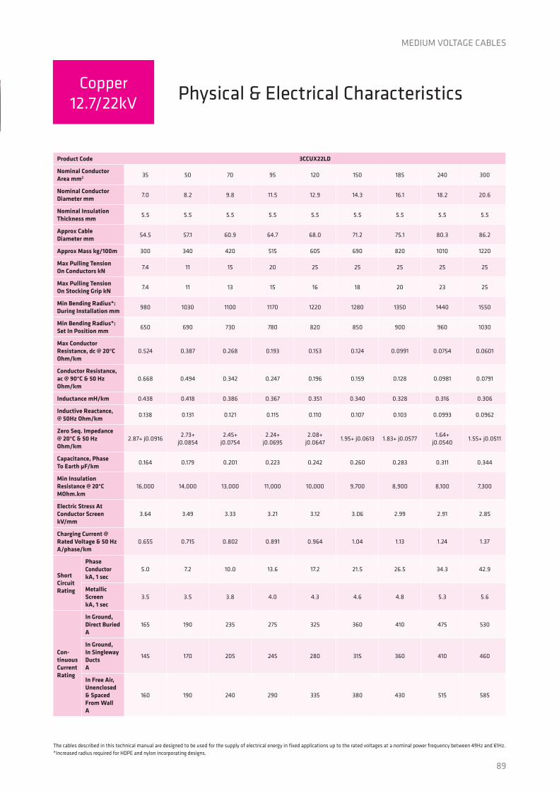
The cables described in this technical manual are designed to be used for the supply of electrical energy in fixed applications up to the rated voltages at a nominal power frequency between 49Hz and 61Hz.*Increased radius required for HDPE and nylon incorporating designs.
MEDIUM VOLTAGE CABLES
Physical & Electrical CharacteristicsCopper
12.7/22kV
Product Code 1CCUX22LD
Nominal Conductor Area mm2 35 50 70 95 120 150 185 240 300 400 500 630
Nominal Conductor Diameter mm
7.0 8.2 9.8 11.5 12.9 14.3 16.1 18.2 20.6 23.5 26.6 30.3
Nominal Insulation Thickness mm
5.5 5.5 5.5 5.5 5.5 5.5 5.5 5.5 5.5 5.5 5.5 5.5
Approx Cable Diameter mm
26.6 27.7 29.5 31.2 32.8 34.2 36.2 38.4 41.1 44.8 48.1 52.0
Approx Mass kg/100m 100 115 140 165 195 225 265 320 385 475 585 725
Max Pulling Tension On Conductor kN
2.5 3.5 4.9 6.7 8.4 11 13 17 21 25 25 25
Max Pulling Tension On Stocking Grip kN
2.5 2.7 3.1 3.4 3.8 4.1 4.6 5.2 5.9 7.0 8.1 9.4
Min Bending Radius*: During Installation mm
480 500 530 560 590 620 650 690 740 810 860 940
Min Bending Radius*: Set In Position mm
320 330 350 370 390 410 430 460 490 540 580 620
Max Conductor Resistance, dc @ 20°C Ohm/km
0.524 0.387 0.268 0.193 0.153 0.124 0.0991 0.0754 0.0601 0.0470 0.0366 0.0283
Conductor Resistance, ac @ 90°C & 50 Hz Ohm/km
0.668 0.494 0.342 0.247 0.196 0.159 0.128 0.0978 0.0788 0.0628 0.0504 0.0410
Inductance, Trefoil Touching mH/km
0.492 0.470 0.435 0.414 0.397 0.384 0.372 0.357 0.346 0.335 0.324 0.315
Inductive Reactance, Trefoil Touching @ 50Hz Ohm/km
0.155 0.148 0.137 0.130 0.125 0.121 0.117 0.112 0.109 0.105 0.102 0.0988
Zero Seq. Impedance@ 20°C & 50 Hz Ohm/km
1.46+ j0.0913
1.32+ j0.0851
1.20+ j0.0751
1.13+ j0.0693
1.09+ j0.0645
1.06+ j0.0611
1.03+ j0.0575
1.01+ j0.0538
0.995+ j0.0509
0.982+ j0.0481
0.973+ j0.0451
0.965+ j0.0426
Capacitance, Phase To Earth µF/km
0.164 0.179 0.200 0.223 0.241 0.259 0.282 0.310 0.343 0.386 0.426 0.473
Min Insulation Resistance @ 20°C MOhm.km
16,000 14,000 13,000 11,000 10,000 9,700 8,900 8,100 7,300 6,500 5,900 5,300
Electric Stress At Conductor Screen kV/mm
3.64 3.49 3.33 3.21 3.12 3.06 2.99 2.91 2.85 2.78 2.73 2.68
Charging Current @ Rated Voltage & 50 Hz A/phase/km
0.652 0.713 0.799 0.888 0.961 1.03 1.12 1.24 1.37 1.54 1.70 1.89
Short Circuit Rating
Phase ConductorkA, 1 sec
5.0 7.2 10.0 13.6 17.2 21.5 26.5 34.3 42.9 57.2 71.5 90.1
Metallic ScreenkA, 1 sec
3.0 3.0 3.0 3.0 3.0 3.0 3.0 3.0 3.0 3.0 3.0 3.0
Con-tinuous Current Rating
In Ground,Direct Buried A
175 205 250 300 335 375 425 490 550 625 705 790
In Ground, In Singleway Ducts A
170 200 245 290 325 360 405 460 515 580 650 730
In Free Air, Unenclosed & Spaced From Wall A
180 215 270 325 375 425 490 575 660 765 880 1005

86
MEDIUM VOLTAGE CABLES
SINGLE CORE HEAVY DUTY SCREENED UNARMOURED
Cable Characteristics
Installation Conditions
Cable Design
CONDUCTOR:
Plain circular compacted copper Maximum Continuous Operating Temperature: 90°C
CONDUCTOR SCREEN:
Extruded semi-conducting compound, bonded to the insulation and applied in the same operation as the insulation
INSULATION:
Cross Linked Polyethylene (XLPE) – standard Ethylene Propylene Rubber (EPR) – alternative
INSULATION SCREEN:
Extruded semi-conducting compound
METALLIC SCREEN:
Plain annealed copper wire: 10kA for nominal 1 second
SHEATH:
Black 5V-90 polyvinyl chloride (PVC) – standardOrange 5V-90 PVC inner plus black high density polyethylene (HDPE) outer – alternativeLow smoke zero halogen (LSOH) – alternative
+90˚C-25˚C
1 (PVC only) 3 (HDPE)
GoodSpray (XPLE)Immersion (EPR)
AcceptableC3Semi-rigid 12D (PVC only)15D (HDPE)
18D (PVC only)25D (HDPE)
IN FREE AIR IN GROUND WITH PROTECTION
IN TRENCH IN GROUNDIN DUCT
Copper12.7/22kV

87
The cables described in this technical manual are designed to be used for the supply of electrical energy in fixed applications up to the rated voltages at a nominal power frequency between 49Hz and 61Hz.*Increased radius required for HDPE and nylon incorporating designs.
MEDIUM VOLTAGE CABLES
Physical & Electrical CharacteristicsCopper
12.7/22kV
Product Code 1CCUX22HD
Nominal Conductor Area mm2 35 50 70 95 120 150 185 240 300 400 500 630
Nominal Conductor Diameter mm
7.0 8.2 9.8 11.5 12.9 14.3 16.1 18.2 20.6 23.5 26.6 30.3
Nominal Insulation Thickness mm
5.5 5.5 5.5 5.5 5.5 5.5 5.5 5.5 5.5 5.5 5.5 5.5
Approx Cable Diameter mm
27.9 29.0 30.8 32.5 34.1 35.5 37.5 39.9 42.4 46.3 49.4 53.5
Approx Mass kg/100m 115 140 185 215 240 270 310 370 430 525 630 770
Max Pulling Tension On Conductor kN
2.5 3.5 4.9 6.7 8.4 11 13 17 21 25 25 25
Max Pulling Tension On Stocking Grip kN
2.5 2.9 3.3 3.7 4.1 4.4 4.9 5.6 6.3 7.5 8.5 10
Min Bending Radius*: During Installation mm
500 520 550 590 610 640 670 720 760 830 890 960
Min Bending Radius*: Set In Position mm
330 350 370 390 410 430 450 480 510 560 590 640
Max Conductor Resistance, dc @ 20°C Ohm/km
0.524 0.387 0.268 0.193 0.153 0.124 0.0991 0.0754 0.0601 0.0470 0.0366 0.0283
Conductor Resistance, ac @ 90°C & 50 Hz Ohm/km
0.668 0.494 0.342 0.247 0.196 0.159 0.128 0.0978 0.0788 0.0627 0.0503 0.0408
Inductance, Trefoil Touching mH/km
0.502 0.479 0.444 0.422 0.405 0.392 0.379 0.365 0.353 0.342 0.330 0.321
Inductive Reactance, Trefoil Touching @ 50Hz Ohm/km
0.158 0.151 0.140 0.133 0.127 0.123 0.119 0.115 0.111 0.108 0.104 0.101
Zero Seq. Impedance@ 20°C & 50 Hz Ohm/km
1.09+ j0.0931
0.783+ j0.0868
0.550+ j0.0767
0.475+ j0.0708
0.435+ j0.0660
0.406+ j0.0625
0.381+ j0.0589
0.358+ j0.0550
0.343+ j0.0520
0.330+ j0.0491
0.320+ j0.0460
0.312+ j0.0435
Capacitance, Phase To Earth µF/km
0.164 0.179 0.200 0.223 0.241 0.259 0.282 0.310 0.343 0.386 0.426 0.473
Min Insulation Resistance @ 20°C MOhm.km
16,000 14,000 13,000 11,000 10,000 9,700 8,900 8,100 7,300 6,500 5,900 5,300
Electric Stress At Conductor Screen kV/mm
3.64 3.49 3.33 3.21 3.12 3.06 2.99 2.91 2.85 2.78 2.73 2.68
Charging Current @ Rated Voltage & 50 Hz A/phase/km
0.652 0.713 0.799 0.888 0.961 1.03 1.12 1.24 1.37 1.54 1.70 1.89
Short Circuit Rating
Phase ConductorkA, 1 sec
5.0 7.2 10.0 13.6 17.2 21.5 26.5 34.3 42.9 57.2 71.5 90.1
Metallic ScreenkA, 1 sec
5.0 7.1 10 10 10 10 10 10 10 10 10 10
Con-tinuous Current Rating
In Ground,Direct Buried A
175 205 250 295 335 370 415 480 535 600 670 740
In Ground, In Singleway Ducts A
170 195 235 275 305 335 370 415 460 510 560 615
In Free Air, Unenclosed & Spaced From Wall A
185 220 270 330 375 425 485 565 645 740 845 960

88
MEDIUM VOLTAGE CABLES
THREE CORE LIGHT DUTY SCREENED UNARMOURED
Cable Characteristics
Installation Conditions
Cable Design
CONDUCTOR:
Plain circular compacted copper Maximum Continuous Operating Temperature: 90°C
CONDUCTOR SCREEN:
Extruded semi-conducting compound, bonded to the insulation and applied in the same operation as the insulation
INSULATION:
Cross Linked Polyethylene (XLPE) – standard Ethylene Propylene Rubber (EPR) – alternative
INSULATION SCREEN:
Extruded semi-conducting compound
METALLIC SCREEN:
Plain annealed copper wire: 3kA for nominal 1 second
SHEATH:
Black 5V-90 polyvinyl chloride (PVC) – standardOrange 5V-90 PVC inner plus black high density polyethylene (HDPE) outer – alternativeLow smoke zero halogen (LSOH) – alternative
+90˚C-25˚C
GoodSpray (XPLE)Immersion (EPR)
AcceptableC3Semi-rigid 12D (PVC only)15D (HDPE)
18D (PVC only)25D (HDPE)
IN FREE AIR IN GROUND WITH PROTECTION
IN TRENCH IN GROUNDIN DUCT
1 (PVC only) 3 (HDPE)
Copper12.7/22kV
89
The cables described in this technical manual are designed to be used for the supply of electrical energy in fixed applications up to the rated voltages at a nominal power frequency between 49Hz and 61Hz.*Increased radius required for HDPE and nylon incorporating designs.
MEDIUM VOLTAGE CABLES
Physical & Electrical CharacteristicsCopper
12.7/22kV
Product Code 3CCUX22LD
Nominal Conductor Area mm2 35 50 70 95 120 150 185 240 300
Nominal Conductor Diameter mm
7.0 8.2 9.8 11.5 12.9 14.3 16.1 18.2 20.6
Nominal Insulation Thickness mm
5.5 5.5 5.5 5.5 5.5 5.5 5.5 5.5 5.5
Approx Cable Diameter mm
54.5 57.1 60.9 64.7 68.0 71.2 75.1 80.3 86.2
Approx Mass kg/100m 300 340 420 515 605 690 820 1010 1220
Max Pulling Tension On Conductors kN
7.4 11 15 20 25 25 25 25 25
Max Pulling Tension On Stocking Grip kN
7.4 11 13 15 16 18 20 23 25
Min Bending Radius*: During Installation mm
980 1030 1100 1170 1220 1280 1350 1440 1550
Min Bending Radius*: Set In Position mm
650 690 730 780 820 850 900 960 1030
Max Conductor Resistance, dc @ 20°C Ohm/km
0.524 0.387 0.268 0.193 0.153 0.124 0.0991 0.0754 0.0601
Conductor Resistance, ac @ 90°C & 50 Hz Ohm/km
0.668 0.494 0.342 0.247 0.196 0.159 0.128 0.0981 0.0791
Inductance mH/km 0.438 0.418 0.386 0.367 0.351 0.340 0.328 0.316 0.306
Inductive Reactance, @ 50Hz Ohm/km
0.138 0.131 0.121 0.115 0.110 0.107 0.103 0.0993 0.0962
Zero Seq. Impedance@ 20°C & 50 Hz Ohm/km
2.87+ j0.09162.73+
j0.08542.45+
j0.07542.24+
j0.06952.08+
j0.06471.95+ j0.0613 1.83+ j0.0577
1.64+ j0.0540
1.55+ j0.0511
Capacitance, Phase To Earth µF/km
0.164 0.179 0.201 0.223 0.242 0.260 0.283 0.311 0.344
Min Insulation Resistance @ 20°C MOhm.km
16,000 14,000 13,000 11,000 10,000 9,700 8,900 8,100 7,300
Electric Stress At Conductor Screen kV/mm
3.64 3.49 3.33 3.21 3.12 3.06 2.99 2.91 2.85
Charging Current @ Rated Voltage & 50 Hz A/phase/km
0.655 0.715 0.802 0.891 0.964 1.04 1.13 1.24 1.37
Short Circuit Rating
Phase ConductorkA, 1 sec
5.0 7.2 10.0 13.6 17.2 21.5 26.5 34.3 42.9
Metallic ScreenkA, 1 sec
3.5 3.5 3.8 4.0 4.3 4.6 4.8 5.3 5.6
Con-tinuous Current Rating
In Ground,Direct Buried A
165 190 235 275 325 360 410 475 530
In Ground, In Singleway Ducts A
145 170 205 245 280 315 360 410 460
In Free Air, Unenclosed & Spaced From Wall A
160 190 240 290 335 380 430 515 585

90
MEDIUM VOLTAGE CABLES
THREE CORE LIGHT DUTY SCREENED ARMOURED
Cable Characteristics
Installation Conditions
Cable Design
CONDUCTOR:
Plain circular compacted copper Maximum Continuous Operating Temperature: 90°C
CONDUCTOR SCREEN:
Extruded semi-conducting compound, bonded to the insulation and applied in the same operation as the insulation
INSULATION:
Cross Linked Polyethylene (XLPE) – standard Ethylene Propylene Rubber (EPR) – alternative
INSULATION SCREEN:
Extruded semi-conducting compound
METALLIC SCREEN:
Plain annealed copper wire: 3kA for nominal 1 second
ARMOURING:
Galvanised steel wires
SHEATH:
Black 5V-90 polyvinyl chloride (PVC) – standardOrange 5V-90 PVC inner plus black high density polyethylene (HDPE) outer – alternativeLow smoke zero halogen (LSOH) – alternative
+90˚C-25˚C
GoodSpray (XPLE)Immersion (EPR)
AcceptableC3Semi-rigid 12D (PVC only)15D (HDPE)
18D (PVC only)25D (HDPE)
IN FREE AIR IN GROUND WITH PROTECTION
IN TRENCH IN GROUNDIN DUCT
1 (PVC only) 3 (HDPE)
3 (Armoured)
Copper12.7/22kV

91
The cables described in this technical manual are designed to be used for the supply of electrical energy in fixed applications up to the rated voltages at a nominal power frequency between 49Hz and 61Hz.*Increased radius required for HDPE and nylon incorporating designs.
MEDIUM VOLTAGE CABLES
Physical & Electrical CharacteristicsCopper
12.7/22kV
Product Code 3CCUX22LDA
Nominal Conductor Area mm2 35 50 70 95 120 150 185
Nominal Conductor Diameter mm
7.0 8.2 9.8 11.5 12.9 14.3 16.1
Nominal Insulation Thickness mm
5.5 5.5 5.5 5.5 5.5 5.5 5.5
Approx Cable Diameter mm
63.6 66.5 70.2 74.3 79.4 82.6 87.0
Approx Mass kg/100m 605 660 760 875 1080 1190 1350
Max Pulling Tension On Conductors kN
7.4 11 15 20 25 25 25
Max Pulling Tension On Stocking Grip kN
7.4 11 15 19 22 24 25
Max Pulling Tension On Amour Wires kN
17 18 20 23 25 25 25
Min Bending Radius*: During Installation mm
1150 1200 1260 1340 1430 1490 1570
Min Bending Radius*: Set In Position mm
760 800 840 890 950 990 1040
Max Conductor Resistance, dc @ 20°C Ohm/km
0.524 0.387 0.268 0.193 0.153 0.124 0.0991
Conductor Resistance, ac @ 90°C & 50 Hz Ohm/km
0.668 0.494 0.342 0.247 0.196 0.159 0.128
Inductance mH/km 0.438 0.418 0.386 0.367 0.351 0.340 0.328
Inductive Reactance, @ 50Hz Ohm/km
0.138 0.131 0.121 0.115 0.110 0.107 0.103
Zero Seq. Impedance@ 20°C & 50 Hz Ohm/km
2.87+j0.0916 2.73+j0.0854 2.45+j0.0754 2.24+j0.0695 2.08+j0.0647 1.95+j0.0613 1.83+j0.0577
Capacitance, Phase To Earth µF/km
0.164 0.179 0.201 0.223 0.242 0.260 0.283
Min Insulation Resistance @ 20°C MOhm.km
16,000 14,000 13,000 11,000 10,000 9,700 8,900
Electric Stress At Conductor Screen kV/mm
3.64 3.49 3.33 3.21 3.12 3.06 2.99
Charging Current @ Rated Voltage & 50 Hz A/phase/km
0.655 0.715 0.802 0.891 0.964 1.04 1.13
Short Circuit Rating
Phase ConductorkA, 1 sec
5.0 7.2 10.0 13.6 17.2 21.5 26.5
Metallic ScreenkA, 1 sec
3.5 3.5 3.8 4.0 4.3 4.6 4.8
Con-tinuous Current Rating
In Ground,Direct Buried A
165 190 235 275 325 360 410
In Ground, In Singleway Ducts A
145 170 205 245 280 315 360
In Free Air, Unenclosed & Spaced From Wall A
160 190 240 290 335 380 430

92
MEDIUM VOLTAGE CABLES
THREE CORE HEAVY DUTY SCREENED UNARMOURED
Cable Characteristics
Installation Conditions
Cable Design
CONDUCTOR:
Plain circular compacted copper Maximum Continuous Operating Temperature: 90°C
CONDUCTOR SCREEN:
Extruded semi-conducting compound, bonded to the insulation and applied in the same operation as the insulation
INSULATION:
Cross Linked Polyethylene (XLPE) – standard Ethylene Propylene Rubber (EPR) – alternative
INSULATION SCREEN:
Extruded semi-conducting compound
METALLIC SCREEN:
Plain annealed copper wire: 10kA for nominal 1 second
SHEATH:
Black 5V-90 polyvinyl chloride (PVC) – standardOrange 5V-90 PVC inner plus black high density polyethylene (HDPE) outer – alternativeLow smoke zero halogen (LSOH) – alternative
+90˚C-25˚C
GoodSpray (XPLE)Immersion (EPR)
AcceptableC3Semi-rigid 12D (PVC only)15D (HDPE)
18D (PVC only)25D (HDPE)
IN FREE AIR IN GROUND WITH PROTECTION
IN TRENCH IN GROUNDIN DUCT
1 (PVC only) 3 (HDPE)
Copper12.7/22kV

93
The cables described in this technical manual are designed to be used for the supply of electrical energy in fixed applications up to the rated voltages at a nominal power frequency between 49Hz and 61Hz.*Increased radius required for HDPE and nylon incorporating designs.
MEDIUM VOLTAGE CABLES
Physical & Electrical CharacteristicsCopper
12.7/22kV
Product Code 3CCUX22HD
Nominal Conductor Area mm2 35 50 70 95 120 150 185 240 300
Nominal Conductor Diameter mm
7.0 8.2 9.8 11.5 12.9 14.3 16.1 18.2 20.6
Nominal Insulation Thickness mm
5.5 5.5 5.5 5.5 5.5 5.5 5.5 5.5 5.5
Approx Cable Diameter mm
54.5 57.1 60.9 64.7 68.0 71.2 75.1 80.3 86.2
Approx Mass kg/100m 310 360 455 550 640 725 850 1040 1240
Max Pulling Tension On Conductors kN
7.4 11 15 20 25 25 25 25 25
Max Pulling Tension On Stocking Grip kN
7.4 11 13 15 16 18 20 23 25
Min Bending Radius*: During Installation mm
980 1030 1100 1170 1220 1280 1350 1440 1550
Min Bending Radius*: Set In Position mm
650 690 730 780 820 850 900 960 1030
Max Conductor Resistance, dc @ 20°C Ohm/km
0.524 0.387 0.268 0.193 0.153 0.124 0.0991 0.0754 0.0601
Conductor Resistance, ac @ 90°C & 50 Hz Ohm/km
0.668 0.494 0.342 0.247 0.196 0.159 0.128 0.0981 0.0791
Inductance mH/km 0.438 0.418 0.386 0.367 0.351 0.340 0.328 0.316 0.306
Inductive Reactance, @ 50Hz Ohm/km
0.138 0.131 0.121 0.115 0.110 0.107 0.103 0.0993 0.0962
Zero Seq. Impedance@ 20°C & 50 Hz Ohm/km
2.16+j0.0916 1.56+j0.0854 1.11+j0.0754 1.03+j0.0695 0.995+j0.0647 0.966+j0.0613 0.941+j0.0577 0.917+j0.0540 0.902+j0.0511
Capacitance, Phase To Earth µF/km
0.164 0.179 0.201 0.223 0.242 0.260 0.283 0.311 0.344
Min Insulation Resistance @ 20°C MOhm.km
16,000 14,000 13,000 11,000 10,000 9,700 8,900 8,100 7,300
Electric Stress At Conductor Screen kV/mm
3.64 3.49 3.33 3.21 3.12 3.06 2.99 2.91 2.85
Charging Current @ Rated Voltage & 50 Hz A/phase/km
0.655 0.715 0.802 0.891 0.964 1.04 1.13 1.24 1.37
Short Circuit Rating
Phase ConductorkA, 1 sec
5.0 7.2 10.0 13.6 17.2 21.5 26.5 34.3 42.9
Metallic ScreenkA, 1 sec
5.1 7.1 10 10 10 10 10 10 10
Con-tinuous Current Rating
In Ground,Direct Buried A
170 200 240 290 330 365 410 475 530
In Ground, In Singleway Ducts A
145 170 210 245 285 320 360 415 465
In Free Air, Unenclosed & Spaced From Wall A
170 200 250 305 350 390 445 520 590

94
MEDIUM VOLTAGE CABLES
THREE CORE HEAVY DUTY SCREENED ARMOURED
Cable Characteristics
Installation Conditions
Cable Design
CONDUCTOR:
Plain circular compacted copper Maximum Continuous Operating Temperature: 90°C
CONDUCTOR SCREEN:
Extruded semi-conducting compound, bonded to the insulation and applied in the same operation as the insulation
INSULATION:
Cross Linked Polyethylene (XLPE) – standard Ethylene Propylene Rubber (EPR) – alternative
INSULATION SCREEN:
Extruded semi-conducting compound
METALLIC SCREEN:
Plain annealed copper wire: 10kA for nominal 1 second
ARMOURING:
Galvanised steel wires
SHEATH:
Black 5V-90 polyvinyl chloride (PVC) – standardOrange 5V-90 PVC inner plus black high density polyethylene (HDPE) outer – alternativeLow smoke zero halogen (LSOH) – alternative
+90˚C-25˚C
GoodSpray (XPLE)Immersion (EPR)
AcceptableC3Semi-rigid 12D (PVC only)15D (HDPE)
18D (PVC only)25D (HDPE)
IN FREE AIR IN GROUND WITH PROTECTION
IN TRENCH IN GROUNDIN DUCT
1 (PVC only) 3 (HDPE)
3 (Armoured)
Copper12.7/22kV

95
The cables described in this technical manual are designed to be used for the supply of electrical energy in fixed applications up to the rated voltages at a nominal power frequency between 49Hz and 61Hz.*Increased radius required for HDPE and nylon incorporating designs.
MEDIUM VOLTAGE CABLES
Physical & Electrical CharacteristicsCopper
12.7/22kV
Product Code 3CCUX22HDA
Nominal Conductor Area mm2 35 50 70 95 120 150 185
Nominal Conductor Diameter mm
7.0 8.2 9.8 11.5 12.9 14.3 16.1
Nominal Insulation Thickness mm
5.5 5.5 5.5 5.5 5.5 5.5 5.5
Approx Cable Diameter mm
63.6 66.5 70.6 74.5 79.4 82.8 87.0
Approx Mass kg/100m 615 680 805 915 1110 1230 1380
Max Pulling Tension On Conductors kN
7.4 11 15 20 25 25 25
Max Pulling Tension On Stocking Grip kN
7.4 11 15 19 22 24 25
Max Pulling Tension On Amour Wires kN
17 18 20 23 25 25 25
Min Bending Radius*: During Installation mm
1150 1200 1270 1340 1430 1490 1570
Min Bending Radius*: Set In Position mm
760 800 850 890 950 990 1040
Max Conductor Resistance, dc @ 20°C Ohm/km
0.524 0.387 0.268 0.193 0.153 0.124 0.0991
Conductor Resistance, ac @ 90°C & 50 Hz Ohm/km
0.668 0.494 0.342 0.247 0.196 0.159 0.128
Inductance mH/km 0.438 0.418 0.386 0.367 0.351 0.340 0.328
Inductive Reactance, @ 50Hz Ohm/km
0.138 0.131 0.121 0.115 0.110 0.107 0.103
Zero Seq. Impedance@ 20°C & 50 Hz Ohm/km
2.16+j0.0916 1.56+j0.0854 1.11+j0.0754 1.03+j0.0695 0.995+j0.0647 0.966+j0.0613 0.941+j0.0577
Capacitance, Phase To Earth µF/km
0.164 0.179 0.201 0.223 0.242 0.260 0.283
Min Insulation Resistance @ 20°C MOhm.km
16,000 14,000 13,000 11,000 10,000 9,700 8,900
Electric Stress At Conductor Screen kV/mm
3.64 3.49 3.33 3.21 3.12 3.06 2.99
Charging Current @ Rated Voltage & 50 Hz A/phase/km
0.655 0.715 0.802 0.891 0.964 1.04 1.13
Short Circuit Rating
Phase ConductorkA, 1 sec
5.0 7.2 10.0 13.6 17.2 21.5 26.5
Metallic ScreenkA, 1 sec
5.1 7.1 10 10 10 10 10
Con-tinuous Current Rating
In Ground,Direct Buried A
170 200 240 290 330 365 410
In Ground, In Singleway Ducts A
145 170 210 245 285 320 360
In Free Air, Unenclosed & Spaced From Wall A
170 200 250 305 350 390 445

132
CABLE SELECTION
Cables should be selected and used such that the product does not present an unacceptable risk or danger to life or property when used in its intended manner.
Cables should also be selected so that they are suitable for the operating environment conditions e.g. use in petrochemical works, need for fire performance, the need for protection against attack by rodents, termites, etc, equipment classification and any other external influences which may exist.
They should also be selected according to the appropriate rated voltage and the cross-sectional area of every conductor such that its current carrying capacity is not less than the maximum sustained current which would normally flow through it, and the short circuit current rating of conductor and screen is adequate for the prospective short circuit and time for which it persists.
In addition, consideration should be given to other relevant factors, such as:
• voltage drop requirements
• operating characteristics of connected equipment
• economics
ENVIRONMENTAL PROTECTION
The standard cable finishes are adequate for normal environmental conditions. However, there are many installations where conditions are much more onerous than normal and some brief notes for protection of cables against hostile environments are given below. Once the type of protective covering to meet environmental conditions has been decided, it is generally possible taking voltage and current ratings into account, to arrive at the type of cable insulation to be used.
OIL REFINERIES AND CHEMICAL PLANTS
Polymeric and elastomeric cables are not compatible with hydrocarbon oils and organic solvents. Such oils and solvents particularly at elevated temperatures are absorbed by the insulation and sheathing materials leading to swelling and resultant damage.
Semi-conductive components on high voltage cables may lose their conductive properties. It follows that where polymeric and elastomeric cables are used in locations where exposure to hydrocarbon oils and organic solvents is likely, a lead sheath is required. The most satisfactory protection for the lead sheath would be a high density polyethylene sheath with steel wire armour.
For casual contact with oil spills, a Nitrile or CSP rubber sheath can be used.
PVC sheaths offer good protection against chemical attack. Specifiers should contact Prysmian for recommendations regarding the protection of cables against harsh chemical environments.
TERMITES, TEREDOES & RODENTS
Special constructions are necessary to resist insects such as termites, as all cables with normal finishes are susceptible to their attack. If cables are installed in locations where termite attack is likely, protection may take the form of one of the following:
• Two helically applied brass tapes, the upper one overlapping the gap in the lower one, may be incorporated into the cable design. In the case of armoured cable the brass tapes may be applied under the bedding of the armour. For unarmoured cable the brass tapes can be applied over the normal PVC or other extruded sheath followed by a PVC sheath over the brass tapes.
• A nylon jacket may be applied over the PVC or other extruded sheath followed by a sacrificial layer of extruded PVC over the nylon to protect it from damage during installation.
• Termitex™ technology incorporated into the cable design, for long term protection.
Chemical treatment of the backfill is no longer recommended because of damage to the environment and the risk to health.
The teredo worm is prevalent in tropical, subtropical and temperate oceans and estuaries. Protection is usually attained by incorporating two brass tapes under the armour of all submarine cables.
In areas liable to attack by rodents, galvanised steel wire armour provides an effective barrier. A layer of nylon covering under the armour provides additional protection from insects.
Prysmian have expertise in designing cables to resist boring insect and rodent attack. Please call the Customer Service Team for advice.
Technical Information

133
EXPOSURE TO MECHANICAL DAMAGE
1. Slight exposure to impact and to tensile stresses. The application of a high density polyethylene sheath can give appreciable added mechanical protection to cables with the normal PVC sheath. This method is suitable for single and multi-core cables.
2. Moderate exposure to impact and to tensile stresses. Single core cables can be armoured with non-ferrous armour wire, usually hard drawn aluminium. For Multicore cables a single layer of galvanised steel wire armour is recommended. The steel wire is necessary if there is likely to be a moderate tensile stress applied to the cable during pulling in or during service. Steel wire armoured cables offer good protection against rugged installation conditions.
3. Severe exposure to impact and tensile stresses. The double wire armour finish offers a very high level of protection against mechanical damage whether it be impact or longitudinal tensile stress such as in subsidence areas and submarine installations on an uneven sea floor.
4. Polymeric protection against impact. Prysmian developed AIRBAG™, which provides enhanced mechanical/impact protection keeping the handling and installation characteristics of unprotected cables.
EXPOSURE TO ULTRA VIOLET RADIATION
Prysmian has special materials designed to prevent UV degradation when exposed to sunlight. To be sure the correct material is used it is necessary to state at the time of enquiry and ordering that the cable will be exposed to sunlight.
FIRE SITUATIONS
The performance of a cable in a fire situation can be a major factor in the choice of cable type. When correctly selected, located and installed cables do not present a fire hazard but in the case of fire initiated elsewhere, cables provide a source of fuel and a possible means of propagation along its length.
Additionally cables can contribute to the emission of smoke and noxious gases injurious to equipment and human health. Evolution of smoke can reduce visibility, which can cause panic and create serious problems in evacuating personnel. The presence of acid gas in the smoke can result in corrosion, damage of electronic and other equipment and can cause intense irritation to the eyes and lungs.
Cables manufactured from PVC and some other traditional materials when exposed to fire will produce dense black smoke and harmful fumes and may propagate fire when installed in bundles. Where these factors are of concern, the use of LSOH sheathed cables is recommended.
On the basis of standards in current use, cables can be divided into the following categories in relation to their behaviour in the presence of fire:
Flame propagation (single cable) – when tested singly, the cable should self-extinguish within a short period of time and within a short distance from the point of application of a Bunsen burner flame. Such cables meet AS/NZS 1660.5.6 and IEC 60332 Part 1 and are often called flame retardant. Such cables will not necessarily prevent propagation along bunches of cables installed together on vertical racks and exposed to a large-scale fire source.
Flame propagation (cable bunches) – when tested installed in defined bunches on a vertical ladder, the cables should not propagate flame more than a limited distance from the point of application of a ribbon burner flame front. Such cables meet AS/NZS 1660.5.1 and IEC 60332 Part 3 and are often called reduced propagation.
Three categories exist in AS/NZS 1660.5.1 according to the volume of combustible material tested, Category A (7 l/m), Category B (3.5 l/m) and Category C (1.5 l/m). It should however be noted that propagation of fire is often a function of installation conditions and appropriate care should be taken to ensure that the test category chosen is representative of the actual installed condition.
Low smoke zero halogen cables – have controlled limits on smoke evolution when cable samples are burnt in a closed 3m cube smoke chamber and controlled limits on acidic and corrosive gases when subject to material pyrolysis in a tube furnace. Such cables meet AS/NZS 1660.5.2 (IEC 61034) for smoke emission and AS/NZS 1660.5.4 (IEC 754-2) for determination of degree of acidity by measurement of pH and conductivity and are often called LSOH.
By nature of their typical intended use the MV power cables of this type may be used where the performance of the cable in case of fire is important, either for limitation of the propagation of flame along cable bunches or the limitation of smoke and corrosive gas emissions.
Reduced flame propagation variants of all cables in this technical manual can be supplied LSOH sheaths for situations where limiting the emission of smoke and corrosive gas from the cables if affected by fire is desirable.
TECHNICAL INFORMATION

134
It is important to know whether the system to which the cable is connected is classified as earthed or unearthed. Supply authority systems are generally, though not always, earthed design. Mining systems are usually the unearthed design. Prysmian products are suitable for voltages that are commonly used in Australia. Voltage is usually expressed in the form Uo/U and Um.
Uo is the rms power frequency voltage between phase and earth.
U is the rms power frequency voltage between phases.
Um is the maximum continuous rms power frequency voltage between any two phases for which the cable is designed. It excludes momentary variations due to fault conditions or sudden disconnection of large loads.
CABLE VOLTAGES
CABLE SELECTION
VOLTAGE RATING
The selection of standard cables for particular supply systems depends on the system voltage and earthing arrangements.
Category A – system in which any phase conductor that comes in contact with earth or an earth conductor is disconnected from the system within 1 minute.
Category B – system which, under fault conditions, is operated for a short time with one phase earthed, not exceeding 8 hours on any occasion and total duration of earth faults in any year not exceeding 125 hours.
Category C – system which does not fall into Categories A and B.
Note: If an earth fault is not automatically and promptly isolated, the extra stresses on the cable insulation during the fault reduce the life of the cable to a certain degree. If the system is expected to be operated fairly often with a permanent earth fault, it may be advisable to classify the system in Category C.
TECHNICAL INFORMATION
Rated Voltages of CablesMax Continuous Operating Voltage
UmkV
General Cables Uo/U
kV
Mining CablesUo/U
kV
1.9/3.3 3.3/3.3 3.6
3.8/6.6 6.6/6.6 7.2
6.35/11 11/11 12
12.7/22 22/22 24
19/33 33/33 36
38/66 72
Max System Voltage(Um) kV
Min Rated (Phase to Earth)Voltage of Cable (Uo) kV
Category A & B Category C
3.6 1.9 3.8
7.2 3.8 6.35
12.0 6.35 12.7
24.0 12.7 19
36.0 19 -

135
CURRENT RATINGS
The current ratings indicated in this manual have been based on the calculation procedures as recommended in IEC 60287 and the following assumptions. Rating factors should be applied to cover any variation.
• Max. continuous conductor temp. = 90°C
• Ambient air temperature = 40°C
• Ambient ground temperature = 25°C
• Depth of laying = 0.8m
• Thermal resistivity of soil = 1.2°C.m/W
• Balanced load, comprising either a single three core cable or three single core cables, in trefoil formation touching throughout, with the screens bonded at both ends of the route.
• Installation conditions:
1. Direct Buried: Cables are installed direct in the ground, with suitable compacted backfill
2. Buried Singleway Ducts: Cables are installed with one cable per duct
3. In Free Air: Cables installed shielded from direct sunlight and with a minimum clearance from any vertical wall of 0.3xCable Dia. and 0.5xCable Dia. for single and three core cables respectively to ensure free air circulation.
In order to select the appropriate cable for a given application, consideration must be given to the nature of the installation. It is not possible to provide a definitive guide to specifying the correct cable type for every situation, this choice must be made by the specifier and/or installer based upon a knowledge of the installation, applicable regulations and the characteristics of available cable designs. General guidance on the use of cable types included has been given above, but for further information and guidance it is recommended to make reference to the appropriate cable standard (e.g. AS/NZS 1429.1 or AS/NZS 4026).
TEMPERATURE LIMITS
In respect of thermal effects the temperature limit given for each cable type is the maximum temperature due to any combination of the heating effect of current in the conductors and ambient conditions. All insulation and sheathing materials become stiffer as their temperature is lowered and due regard has been taken of this factor in the guidance on minimum installation temperature.
The materials used for these cables are compatible with temperatures of 90ºC for continuous operation and 250ºC for short circuit conditions of up to 5 seconds.
The fault ratings for the conductors and the metallic screens are provided for a time period of 1 second. When other times (t) between 0.2 and 5 seconds are required, the appropriate rating may be obtained by multiplying the 1 second rating by the factor: 1/√t.
The ratings for the screens are based upon the traditional adiabatic method, which provides a substantial safety margin when account is taken of the heat loss occurring in practice. The non-adiabatic method to IEC standards can be used according to AS/NZS 1429.1 when agreed between the purchaser and supplier. This can provide substantial systems savings.
Short circuit capacity that is related to the energy expended during a short circuit. It is equated to the mass x specified heat capacity x temperature change in the conductor. Two types of conditions have to be considered – symmetrical and earth short circuit currents. Various cable designs have different nominated maximum temperatures after short circuit, depending usually on the type of insulation and sheathing, and these temperatures should not be exceeded.
Economics important criteria related to cable economics are the initial system cost and annual cost of losses. Economics are generally considered on a present value calculation based on initial cost and discounted cost of losses. Data provided in the tables assists specifiers to estimate purchase and running costs.
TECHNICAL INFORMATION
136
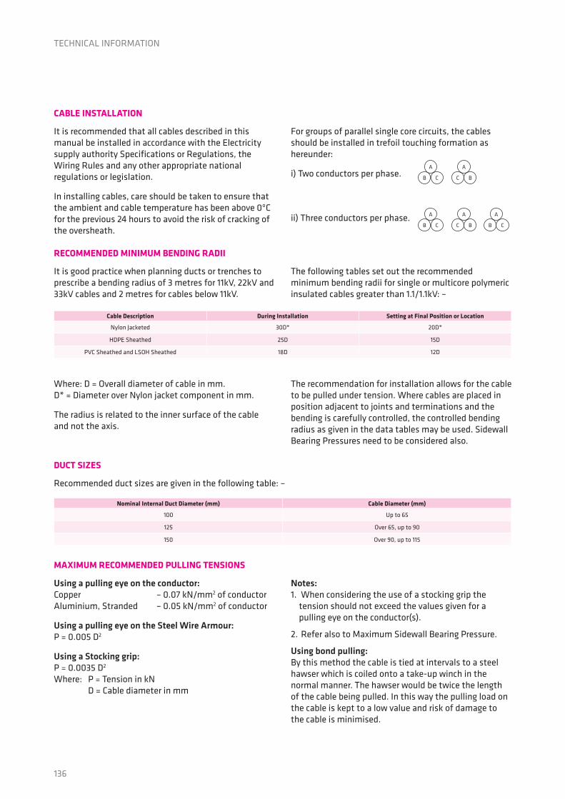
It is recommended that all cables described in this manual be installed in accordance with the Electricity supply authority Specifications or Regulations, the Wiring Rules and any other appropriate national regulations or legislation.
In installing cables, care should be taken to ensure that the ambient and cable temperature has been above 0ºC for the previous 24 hours to avoid the risk of cracking of the oversheath.
For groups of parallel single core circuits, the cables should be installed in trefoil touching formation as hereunder:
i) Two conductors per phase.
ii) Three conductors per phase.
It is good practice when planning ducts or trenches to prescribe a bending radius of 3 metres for 11kV, 22kV and 33kV cables and 2 metres for cables below 11kV.
The following tables set out the recommended minimum bending radii for single or multicore polymeric insulated cables greater than 1.1/1.1kV: –
Recommended duct sizes are given in the following table: –
Where: D = Overall diameter of cable in mm. D* = Diameter over Nylon jacket component in mm.
The radius is related to the inner surface of the cable and not the axis.
The recommendation for installation allows for the cable to be pulled under tension. Where cables are placed in position adjacent to joints and terminations and the bending is carefully controlled, the controlled bending radius as given in the data tables may be used. Sidewall Bearing Pressures need to be considered also.
Using a pulling eye on the conductor: Copper – 0.07 kN/mm2 of conductor Aluminium, Stranded – 0.05 kN/mm2 of conductor
Using a pulling eye on the Steel Wire Armour: P = 0.005 D2
Using a Stocking grip: P = 0.0035 D2 Where: P = Tension in kN D = Cable diameter in mm
Notes:1. When considering the use of a stocking grip the
tension should not exceed the values given for a pulling eye on the conductor(s).
2. Refer also to Maximum Sidewall Bearing Pressure.
Using bond pulling: By this method the cable is tied at intervals to a steel hawser which is coiled onto a take-up winch in the normal manner. The hawser would be twice the length of the cable being pulled. In this way the pulling load on the cable is kept to a low value and risk of damage to the cable is minimised.
CABLE INSTALLATION
RECOMMENDED MINIMUM BENDING RADII
DUCT SIZES
MAXIMUM RECOMMENDED PULLING TENSIONS
TECHNICAL INFORMATION
Cable Description During Installation Setting at Final Position or Location
Nylon Jacketed 30D* 20D*
HDPE Sheathed 25D 15D
PVC Sheathed and LSOH Sheathed 18D 12D
Nominal Internal Duct Diameter (mm) Cable Diameter (mm)
100 Up to 65
125 Over 65, up to 90
150 Over 90, up to 115
A
A
A
A A
B
B
C
C B
C
C
B
B C

137
TECHNICAL INFORMATION
MAXIMUM SIDEWALL BEARING PRESSURE
Another factor which can limit the maximum tension that a cable can withstand is the sidewall bearing pressure exerted on a cable in duct bends and elbows. The sidewall bearing pressure formula is expressed as:
SWBP = [W2 + (T/(0.0098 x R))2] (equation 1) as most of the time, [T/(0.0098 x R)]2 >> W2 equation 1 can therefore be simplified as follows:
SWBP ≈ T/(0.0098 x R) (equation 2) From eqn. 2 => T = 0.0098 x R x SWBP (equation 3) From eqn. 2 => R = T / (0.0098 x SWBP) (equation 4)
Where: SWBP = sidewall bearing pressure (kg/m) W = weight of cable per unit length (kg/m) T = cable pulling tension (kN) R = radius of the bend or elbow (m)
The recommended maximum SWBP for sheathed cables shall be 1450kg/m.
Examples:
1. To find out the maximum pulling tension of a 12.7/22kV 240mm2 copper single core PVC sheathed cable based on its minimum recommended bending radius:
First calculate the minimum recommended bending radius without considering SWBP: = 18 x Cable Diameter = 18 x 40.5mm = 729mm
Then calculate the maximum pulling tensions:a) Maximum pulling tension for straight pull:
T = 0.07 kN/mm2 x 240 mm2 = 16.8 kN
b) Maximum pulling tension when taking maximum SWBP into consideration.
From Equation 3: T = 0.0098 x 0.729 x 1450 = 10.4 kN
We have to select the lesser of the two pulling tensions, i.e. 10.4kN. In this example, the maximum SWBP dictates the maximum pulling tension.
2. To find out the minimum bending radius for the same cable if we do need a pulling tension of 16.8kN:
From Equation 4: R = 16.8 / (0.0098 x 1450) = 1.2m
JOINTS AND TERMINATIONS
Whilst jointing and terminating of Medium Voltage Polymeric Cables is routine, care is needed to maintain clean working conditions and in ensuring that the insulation semiconducting screen is completely removed and properly connected at the stress control areas. Reference should be made to literature for suitable systems available from Prysmian.
TESTS AFTER INSTALLATION
High Voltage d.c. testing of primary insulation is not recommended and can be detrimental to the cable and accessories. AS/NZS 1429.1 describes an a.c. voltage test at power frequency that should be applied for 24 hours at the normal operating voltage of the system. A sheath integrity test (e.g. with a 1000 Volt minimum rated insulation resistance tester) may be applied between the outer-most metallic layer and the earth to identify post-installation damage, provided the metallic layer is isolated from earth at the joints, terminations, etc.
SHORT CIRCUIT FORCES
When single core cables are installed touching, special attention should be given to cleating and strapping arrangements to contain the repulsive forces under short circuit conditions. Longitudinal thrust and tensions in cable conductors may be considerable and may cause buckling of conductors and other damage in a joint or termination. When cables are installed, provision should be made to accommodate the resulting longitudinal forces on terminations and joints. Sharp bends and fixings at a bend should be avoided.
PREVENTION OF MOISTURE INGRESS
Care should be exercised during installation to avoid any damage to cable coverings. This is important in wet or other aggressive environments. The protective cap should not be removed from the ends of the cable until immediately prior to termination or jointing. When the caps have been removed the unprotected ends of the cable should not be exposed to moisture.
The possibility of damage to moisture seals during handling and installation or during storage of the cable should be considered and where such damage may have occurred, the seals should be inspected and remade if necessary.

138
CABLE DESIGN SERVICE
Prysmian offer their customers a full cable design service, either to give advice on the selection of the most appropriate cable from this technical manual for a particular application or to design a specific cable for any particular installation condition. This service is backed by an experienced team of design engineers working under a Quality Management System approved to AS/NZS ISO 9001.
The Prysmian commitment to new product introduction and development ensures effective and reliable designs are developed and assessed in our own research laboratories.
Prysmian is also able to offer aerial cables including OPGW, water blocked designs and high voltage cables to 400kV. Cable termination and identification systems are also available as part of the Prysmian systems approach.
QUALITY ASSURANCE
All Prysmian MV power cables are manufactured under the Prysmian Quality Management System. This system has received certification by Quality Assurance Services that it meets the requirements of AS/NZS ISO 9001.
TECHNICAL INFORMATION
139
Technical Information - Ratings InformationTECHNICAL INFORMATION
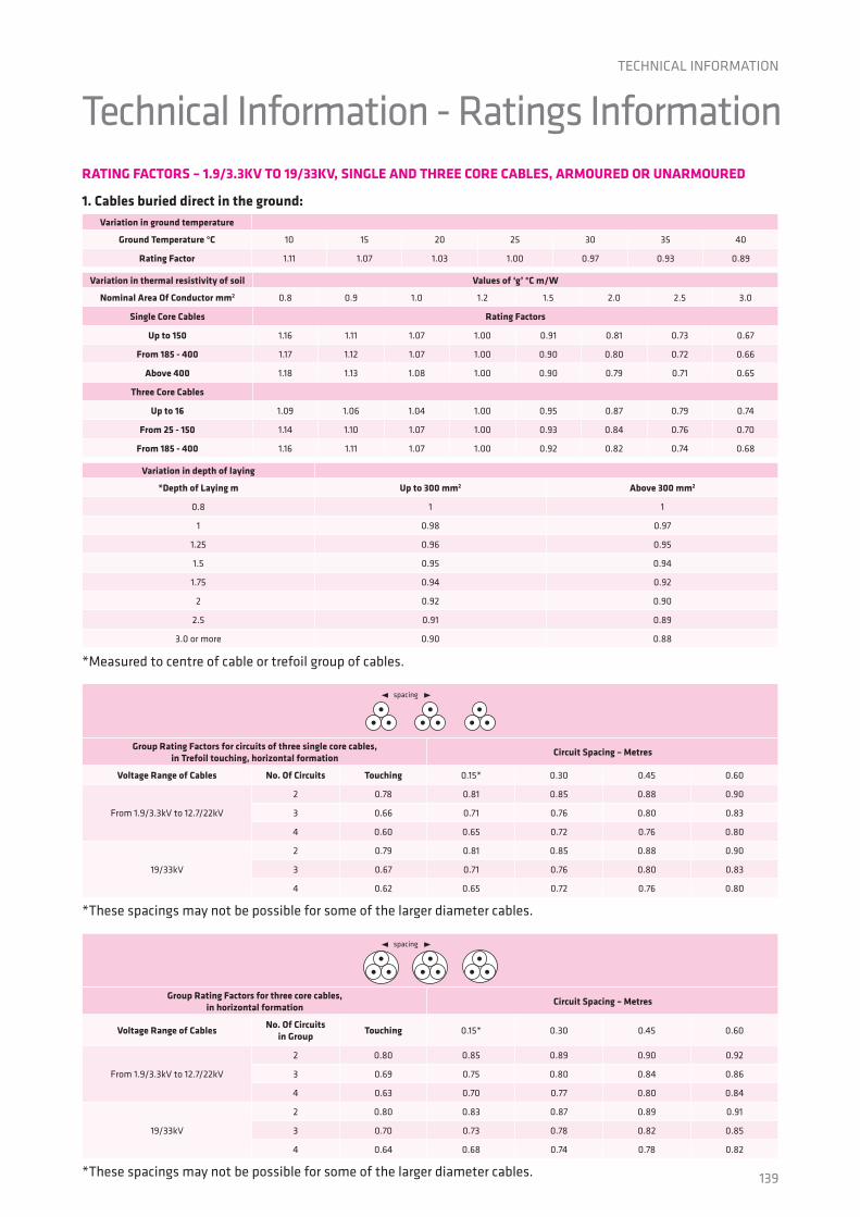
1. Cables buried direct in the ground: Variation in ground temperature
Ground Temperature °C 10 15 20 25 30 35 40
Rating Factor 1.11 1.07 1.03 1.00 0.97 0.93 0.89
Group Rating Factors for circuits of three single core cables,in Trefoil touching, horizontal formation
Circuit Spacing – Metres
Voltage Range of Cables No. Of Circuits Touching 0.15* 0.30 0.45 0.60
From 1.9/3.3kV to 12.7/22kV
2 0.78 0.81 0.85 0.88 0.90
3 0.66 0.71 0.76 0.80 0.83
4 0.60 0.65 0.72 0.76 0.80
19/33kV
2 0.79 0.81 0.85 0.88 0.90
3 0.67 0.71 0.76 0.80 0.83
4 0.62 0.65 0.72 0.76 0.80
Group Rating Factors for three core cables,in horizontal formation
Circuit Spacing – Metres
Voltage Range of CablesNo. Of Circuits
in GroupTouching 0.15* 0.30 0.45 0.60
From 1.9/3.3kV to 12.7/22kV
2 0.80 0.85 0.89 0.90 0.92
3 0.69 0.75 0.80 0.84 0.86
4 0.63 0.70 0.77 0.80 0.84
19/33kV
2 0.80 0.83 0.87 0.89 0.91
3 0.70 0.73 0.78 0.82 0.85
4 0.64 0.68 0.74 0.78 0.82
Variation in depth of laying
*Depth of Laying m Up to 300 mm2 Above 300 mm2
0.8 1 1
1 0.98 0.97
1.25 0.96 0.95
1.5 0.95 0.94
1.75 0.94 0.92
2 0.92 0.90
2.5 0.91 0.89
3.0 or more 0.90 0.88
RATING FACTORS – 1.9/3.3KV TO 19/33KV, SINGLE AND THREE CORE CABLES, ARMOURED OR UNARMOURED
Variation in thermal resistivity of soil Values of ‘g’ °C m/W
Nominal Area Of Conductor mm2 0.8 0.9 1.0 1.2 1.5 2.0 2.5 3.0
Single Core Cables Rating Factors
Up to 150 1.16 1.11 1.07 1.00 0.91 0.81 0.73 0.67
From 185 - 400 1.17 1.12 1.07 1.00 0.90 0.80 0.72 0.66
Above 400 1.18 1.13 1.08 1.00 0.90 0.79 0.71 0.65
Three Core Cables
Up to 16 1.09 1.06 1.04 1.00 0.95 0.87 0.79 0.74
From 25 - 150 1.14 1.10 1.07 1.00 0.93 0.84 0.76 0.70
From 185 - 400 1.16 1.11 1.07 1.00 0.92 0.82 0.74 0.68
*Measured to centre of cable or trefoil group of cables.
*These spacings may not be possible for some of the larger diameter cables.
*These spacings may not be possible for some of the larger diameter cables.
spacing
spacing

140
2. Cables in singleway ducts, buried direct in the ground: Variation in ground temperature
Ground Temperature °C 10 15 20 25 30 35 40
Rating Factor 1.11 1.07 1.03 1.00 0.97 0.93 0.89
Group Rating Factors for single core cables in single way ducts,laid in Trefoil touching, horizontal formation
Circuit Spacing – Metres
Voltage Range of Cables No. Of Circuits Touching 0.45 0.60
From 1.9/3.3kV to 12.7/22kV
2 0.85 0.88 0.90
3 0.75 0.80 0.83
4 0.70 0.76 0.80
19/33kV
2 0.85 0.88 0.90
3 0.76 0.80 0.83
4 0.71 0.76 0.80
Group Rating Factors for three core cables in singleway ducts,in horizontal formation
Circuit Spacing – Metres
Voltage Range of CablesNo. Of Ducts
in GroupTouching 0.30 0.45 0.60
From 1.9/3.3kV to 12.7/22kV
2 0.88 0.91 0.93 0.90
3 0.80 0.84 0.87 0.84
4 0.75 0.81 0.84 0.80
19/33kV
2 0.87 0.89 0.92 0.93
3 0.78 0.82 0.85 0.87
4 0.73 0.78 0.82 0.85
Variation in depth of laying Rating Factors
*Depth of Laying m Single Core Multicore
0.8 1 1
1 0.98 0.99
1.25 0.95 0.97
1.5 0.93 0.96
1.75 0.92 0.95
2 0.90 0.94
2.5 0.89 0.93
3.0 or more 0.88 0.92
Variation in thermal resistivity of soil Values of ‘g’ °C m/W
Nominal Area Of Conductor mm2 0.8 0.9 1.0 1.2 1.5 2.0 2.5 3.0
Single Core Cables Rating Factors
Up to 150 1.10 1.07 1.05 1.00 0.94 0.87 0.81 0.75
From 185 - 400 1.11 1.08 1.06 1.00 0.94 0.86 0.79 0.73
Above 400 1.13 1.09 1.06 1.00 0.93 0.84 0.77 0.70
Three Core Cables
Up to 16 1.05 1.04 1.03 1.00 0.97 0.92 0.87 0.83
From 25 - 150 1.07 1.05 1.03 1.00 0.96 0.90 0.85 0.78
From 185 - 400 1.09 1.06 1.04 1.00 0.95 0.87 0.82 0.76
*Measured to centre of cable or trefoil group of cables.
*These spacings may not be possible for some of the larger diameter cables.
*These spacings may not be possible for some of the larger diameter cables.
spacing
spacing
TECHNICAL INFORMATION

141
Grouping of cables in air:
Derating is not necessary if the following minimum clearance between adjacent circuits can be maintained 1 The horizontal clearance is not less than twice the diameter of an individual cable. 2 The vertical clearance is not less than four times the diameter of an individual cable. 3 Where the number of circuits is more than three, they are installed in a horizontal plane.
AS 1018 Partial discharge measurements
AS/NZS 1026 Electric cables – Impregnated paper insulated for working voltages up to and including 19/33 (36)kV
AS/NZS 1125 Conductors in insulated electric cables and flexible cords
AS/NZS 1429.1 Electric cables – Polymeric insulated Part 1: electric cables for working voltages 1.9/3.3 (3.6)kV up to and including 19/33 (36)kV
AS/NZS 1660 Test methods for electric cables, cords and conductors
AS 1931 High-voltage testing techniques
AS/NZS 2857 Timber drums for insulated electric cables and bare conductors
AS/NZS 2893 Electric cables – lead and lead alloy sheaths – composition
AS/NZS 3008 Electrical installations – selection of cables
AS/NZS 3808 Insulating and sheathing materials for electric cables
AS/NZS 3863 Galvanized mild steel wire for armouring cables
AS 3983 Metal drums for insulated electric cables and bare conductors
AS/NZS 4026 Electric cables – for underground residential distribution systems
IEC 754-2 Test on gases evolved during combustion of electric cables, Part 2: Determination of degree of acidity of gases evolved during the combustion of materials taken from electric cables by measuring pH and conductivity
IEC 60287 Electric cables – calculation of the current rating
IEC 60332-1 Tests on electric and optical fibre cables under fire conditions, Part 1: Test for vertical flame propagation for a single insulated wire or cable
IEC 60332-3 Tests on electric cables under fire conditions, Part 3: Test for vertical flame spread of vertically-mounted bunched wires or cables
IEC 60502-2 Power cables with extruded insulation and their accessories for rated voltages from 1kV (Um = 1.2kV) up to 30kV (Um = 36kV) - Part 2: Cables for rated voltages from 6kV (Um = 7.2kV) up to 30kV (Um = 36kV)
IEC 60949 Calculation of thermally permissible short-circuit currents, taking into account non-adiabatic heating effects
IEC 60986 Short-circuit temperature limits of electric cables with a rated voltages from 6kV (Um = 7.2kV) up to 30kV (Um = 36kV)
IEC 61034 Measurement of smoke density of cables burning under defined conditions
3. Cables installed in free air: Variation in ambient air temperature
Ambient Air Temperature °C 15 20 25 30 35 40 45 50
Rating Factor 1.26 1.20 1.15 1.10 1.05 1.00 0.94 0.88
TECHNICAL INFORMATION
General Information

142
Notes

143
Notes

Prysmian Cables & Systems Australia Pty LtdPh: 1300 300 304 Fx: 1300 300 307
1 Heathcote Road, Liverpool 2170 NSW, AustraliaEmail: [email protected]
www.prysmian.com.au
Vers
ion
1, A
pril
2014
, PR
Y004
2