Embed Size (px)
DESCRIPTION
Project Presentation on Z- Source Converter Comparision between single switch & double switch Z- Source Converter
Citation preview
COMPARISON BETWEEN SINGLE SWITCH AND TWO SWITCHES Z-
SOURCE CONVERTER
OUTLINEIntroductionObjectiveSteady state operation of ZSCDynamic modeling of ZSCSimulation parameterStep response of the systemComparisonResultConclusionFuture worksReferences
INTRODUCTIONThe Z-source converter (ZSC) is an alternative power
conversion topology that can both buck and boost the input voltage using passive components. It uses a unique LC impedance network for coupling the converter main circuit to the power source, which provides a way of boosting the input voltage, a condition that cannot be obtained in the traditional inverters. It also allows the use of the shoot-through switching state, which eliminates the need for dead-times that are used in the traditional inverters to avoid the risk of damaging the inverter circuit.
OBJECTIVE Most of the papers are on Z-source inverter but some recent
paper discussed about Z-source DC-DC converter. The limitations of traditional power converter and Z-source converter so far discussed are mentioned below.
Buck and Boost converter provides output voltage always in same polarity with input.
Buck-boost and cuk converter always provide voltage polarity reversal.
Contd..The single switch ZSC model can only boost the output
voltage with same polarity within duty cycle 0 to 0.5 and cannot be used for buck operation. As the output voltage reversal is not possible it is not suitable for 4-quadrant operation. For duty cycle greater than 0.5 it gives the absurd result because during shoot-through state both switch and diode remains on simultaneously. Figure 1 shows the single switch ZSC model.
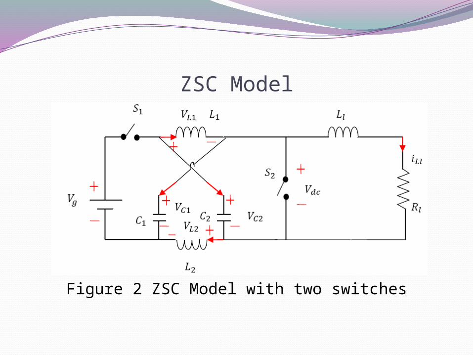
Contd..To overcome the above mentioned problem my proposed model is given in Figure 2 which is ZSC model with two switches. This proposed model is capable for both buck and boost operation. For duty cycle 0 -0.5 it provides the voltage with same polarity and above 0.5 voltage reversal is possible which makes the converter to be used in four-quadrant operation.
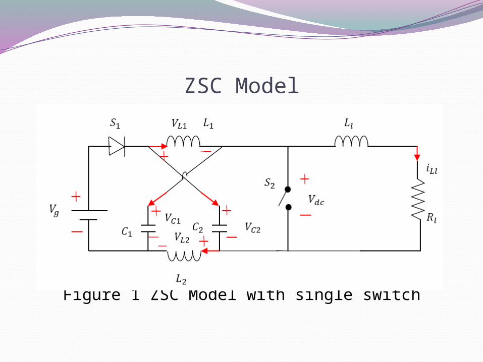
ZSC Model
Figure 1 ZSC Model with single switch
ZSC Model
Figure 2 ZSC Model with two switches
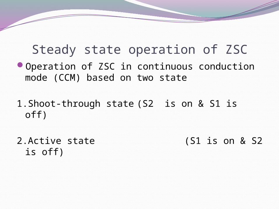
Steady state operation of ZSCOperation of ZSC in continuous conduction mode (CCM)
based on two state
1.Shoot-through state (S2 is on & S1 is off)
2.Active state (S1 is on & S2 is off)
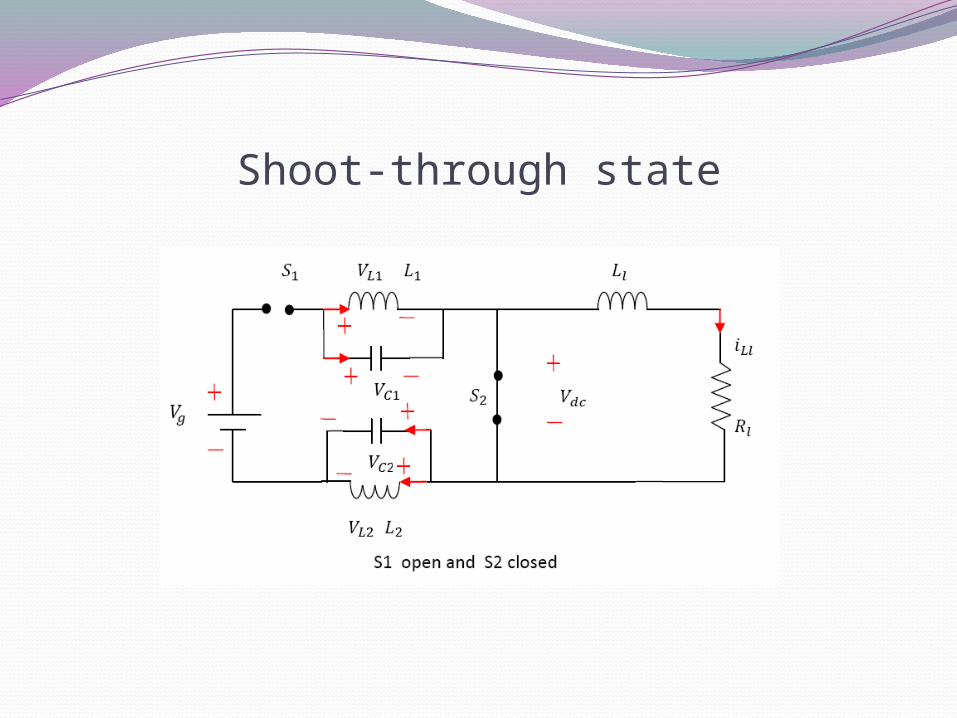
Shoot-through state
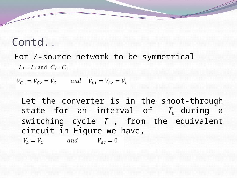
Contd..For Z-source network to be symmetrical
Let the converter is in the shoot-through state for an interval of T0 during a switching cycle T , from the equivalent circuit in Figure we have,
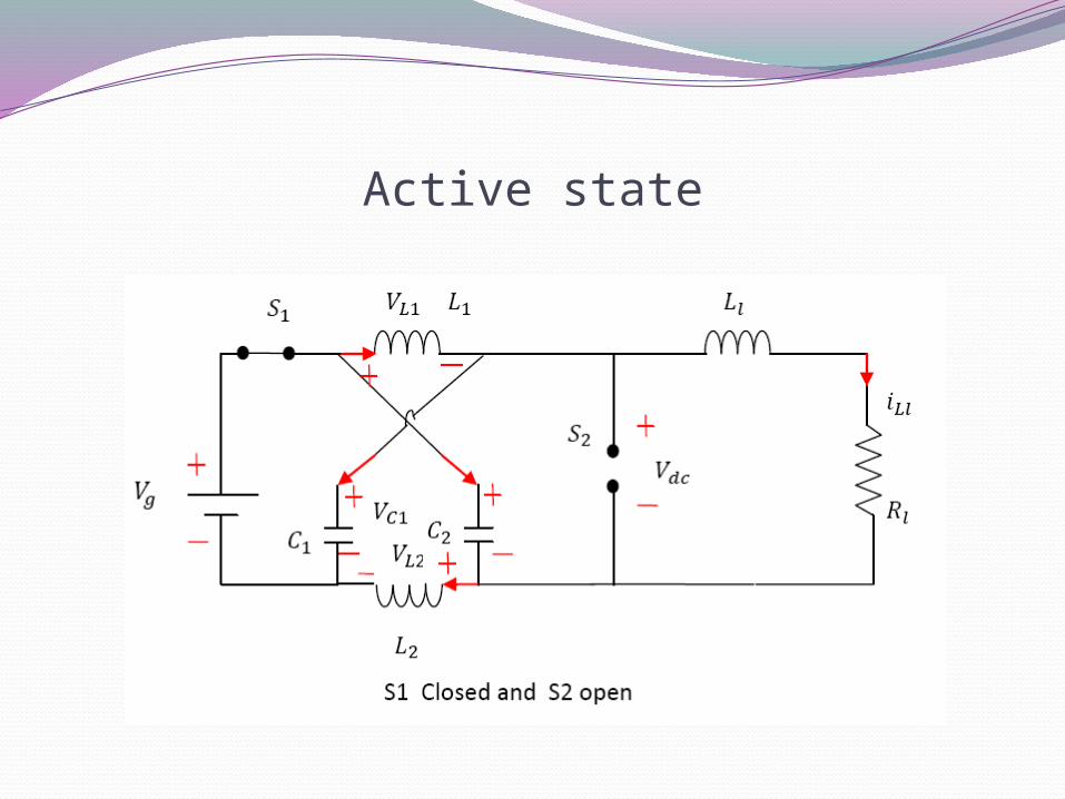
Active state
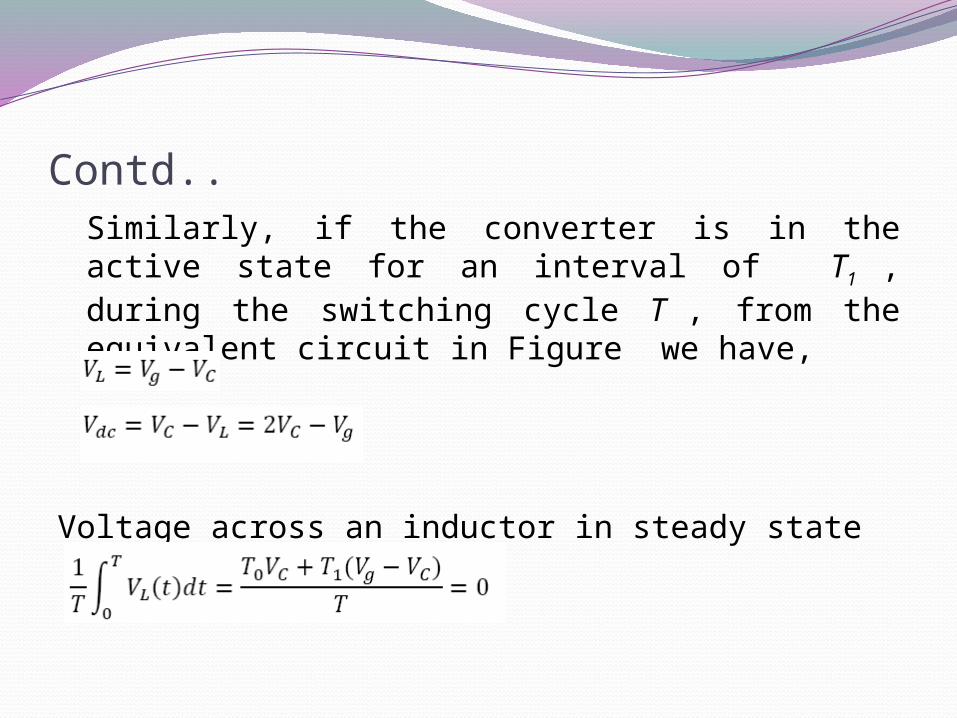
Contd..Similarly, if the converter is in the active state for an interval of T1 , during the switching cycle T , from the equivalent circuit in Figure we have,
Voltage across an inductor in steady state
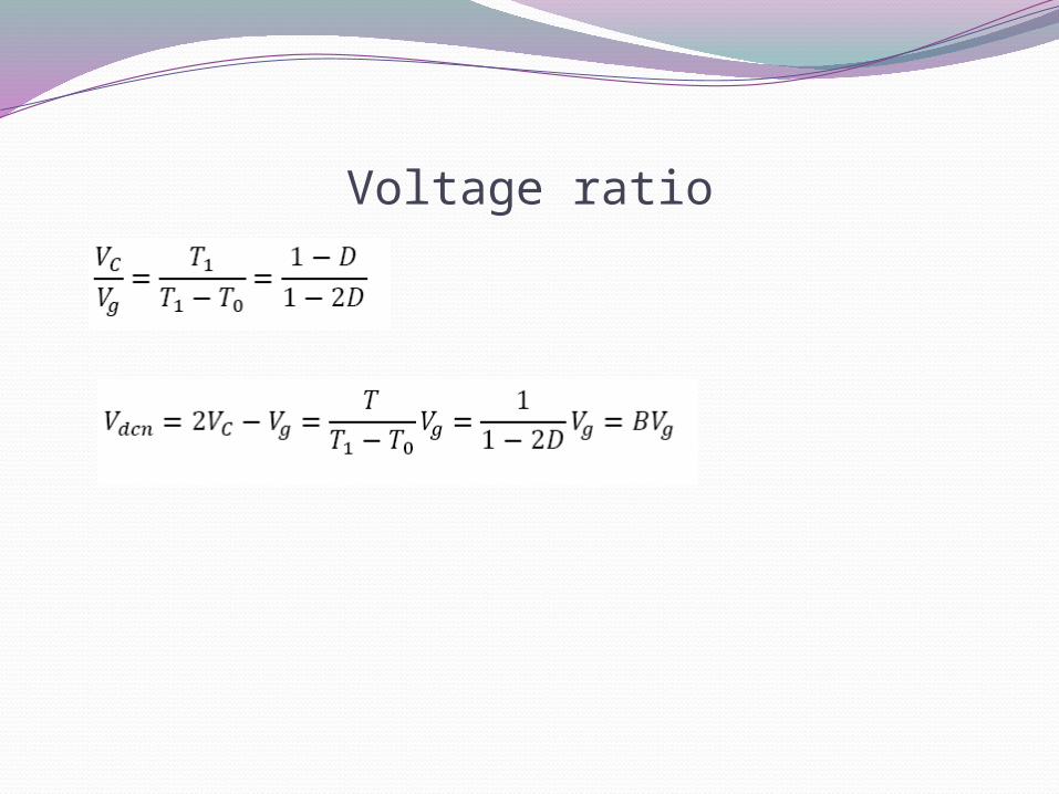
Voltage ratio
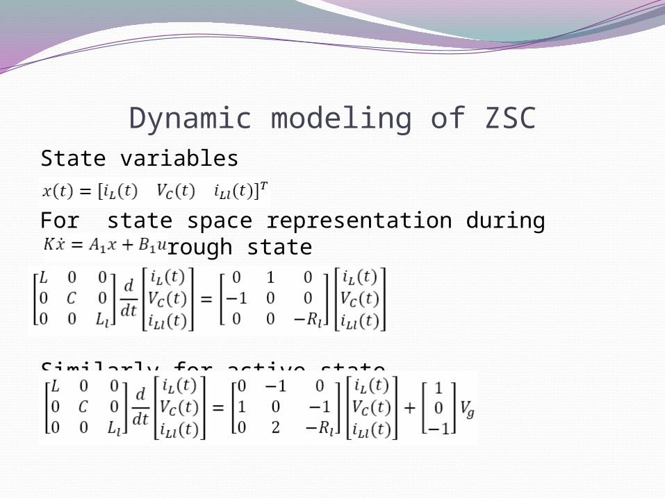
Dynamic modeling of ZSCState variables
For state space representation during shoot-through state
Similarly for active state

Contd..To find the equilibrium values of state variables
Now the equilibrium values are
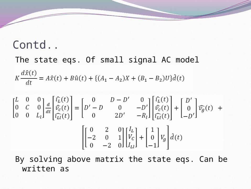
Contd..The state eqs. Of small signal AC model
By solving above matrix the state eqs. Can be written as
Contd..
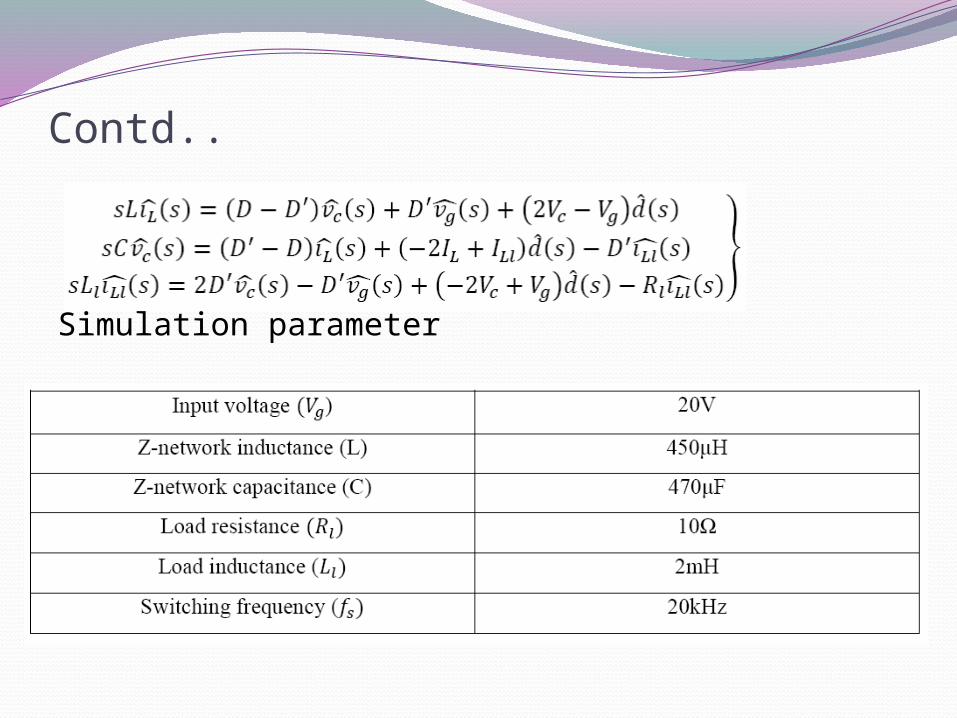
Simulation parameter
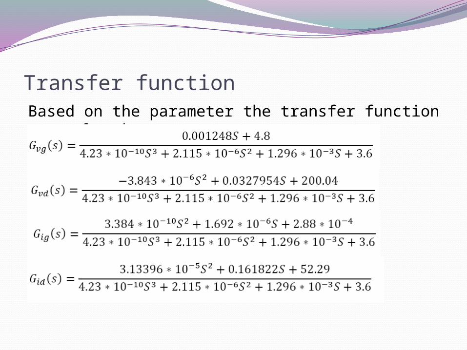
Transfer functionBased on the parameter the transfer function are found as
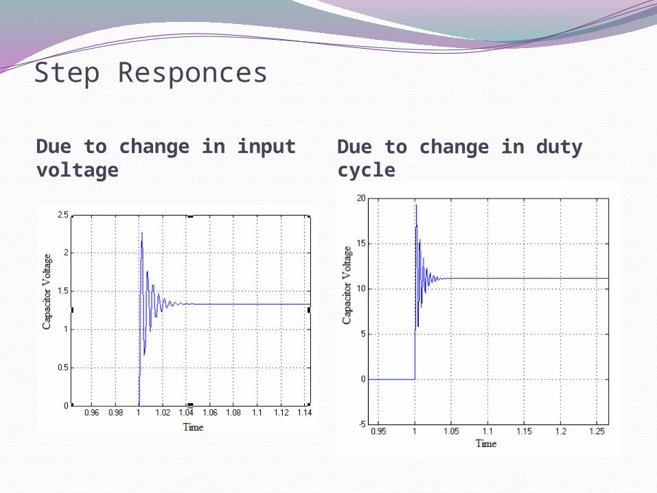
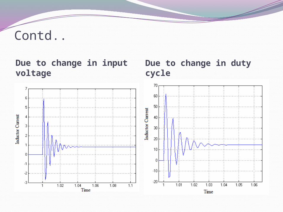
Step Responces
Due to change in input voltage
Due to change in duty cycle
Contd..
Due to change in input voltage
Due to change in duty cycle
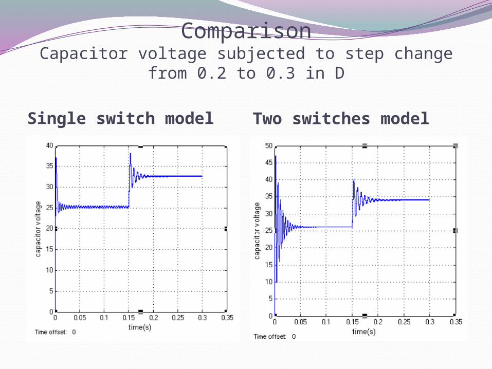
ComparisonCapacitor voltage subjected to step change from 0.2 to 0.3 in D
Single switch model Two switches model
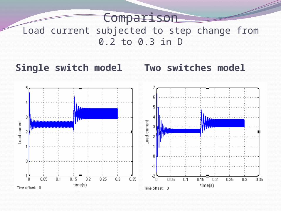
ComparisonLoad current subjected to step change from 0.2 to 0.3 in D
Single switch model Two switches model
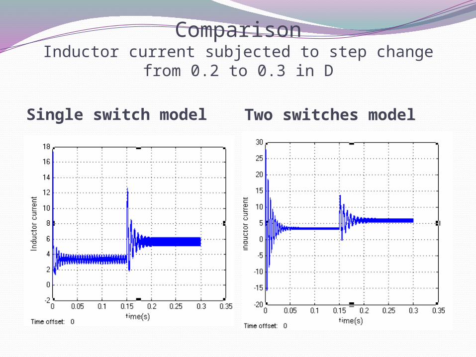
ComparisonInductor current subjected to step change from 0.2 to 0.3 in D
Single switch model Two switches model
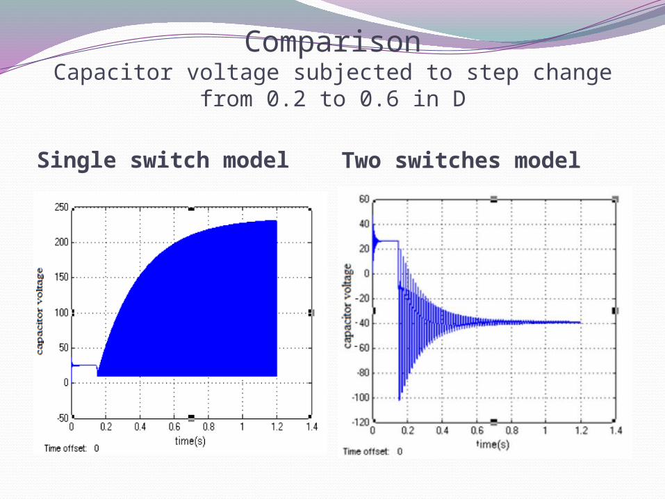
ComparisonCapacitor voltage subjected to step change from 0.2 to 0.6 in D
Single switch model Two switches model
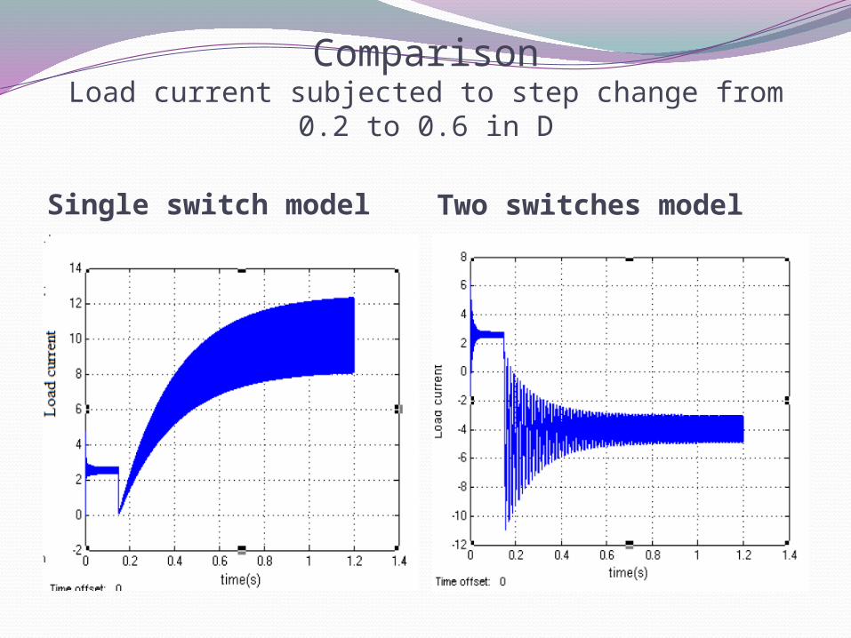
ComparisonLoad current subjected to step change from 0.2 to 0.6 in D
Single switch model Two switches model
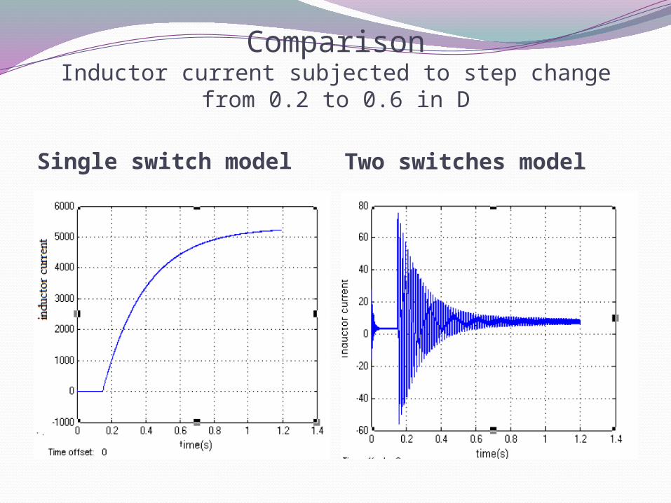
ComparisonInductor current subjected to step change from 0.2 to 0.6 in D
Single switch model Two switches model
ConclusionsSystems involving power converters are becoming more common in applications like alternative energy sources and hybrid electric vehicles (HEV). Efficiency, low cost and reliability are major objectives for power electronics designers. Classical power converter topologies still give satisfactory results and their performances are being improved by advanced control techniques. New topologies in power conversion are also being introduced and give better results in some applications. The Z-source converter (ZSC) is a new power conversion topology that is very promising in power conditioning of alternative energy sources and applications like HEVs and utility interfacing. Unique buck and boost capability of the ZSC allows a wider input voltage range and eliminates the usage of DC/DC boost stage which improves overall efficiency. Also, the shoot-through state is allowed and the system reliability is improved.
Future works
The small signal model of ZSC derived in this research is used for current programmed mode (CPM) and voltage mode (VM) of ZSC. By the help of transfer function controllers are designed for both VM and CPM control.
In this research the experimental verifications are carried out using the simplified ZSC. The Z-source inverter (ZSI) can be implemented by replacing the parallel switch with an inverter bridge.
The small signal model used in this research assumed ideal components. A new model including the non-idealities can be derived for more accurate transfer functions.
References
S.Hasan Saeed, Automatic control Systems with MATLAB programs.3rd edition. Mhummad H.Rashid, Power Electronics circuits,Devices, and Applications,3rd edition. Nagoor kani, control system,Analysis and design of control system in state space. Bimal K. Bose, Modern Power Electronics and AC Drives, Prentice-Hall, Upper Saddle River NJ,
2001. Gokhan Sen and Malik Elbuluk,” Voltage and Current Programmed Modes in Control of the Z-source
converter”IEEE Transaction 2008 Fang Z. Peng, "Z-Source Inverter", IEEE Transactions on Industrial Applications, vol. 39, no. 2, pp.
504-510, Mar./Apr. 2003. B. Kuo, Automatic Control Systems, Prentice Hall, IL, 1994. Ray Ridley, A New Small-Signal Model For Current Mode Control, PhD Dissertation Blacksburg,
Virginia, 1990. J. Liu, J. Hu and L. Xu, "Dynamic Modeling and Analysis of Z-Source Converter —
Derivation of AC Small Signal Model and Design-Oriented Analysis", IEEE Transactions on Power Electronics, vol. 22, no. 5, Sept. 2007, pp. 1786-1796.
P. Loh, D. M. Vilathgamuwa and C. J. Gajanayake, "Transient Modeling and Analysis of
Pulse-Width Modulated Z-Source Inverter", IEEE Transactions on Power Electronics, vol.2, no. 22, Jan. 2007, pp. 169-177.
References
X. Ding, Z. Qian, S. Yang, Bin Cui, F. Z. Peng, “A PID Control Strategy for DClink Boost Voltage in Z-Source Inverter”, IEEE Applied Power Electronics Conference, Feb-Mar. 2007, pp. 1145-1148.
X. Ding , Z. Qian, S. Yang, Bin Cui, F. Z. Peng, “A Direct Peak DC-link Boost Control Strategy for Z-Source Inverter”, IEEE Applied Power Electronics Conference, Feb-Mar. 2007, pp. 648-653.
Poh chiang loh and D. M. Vilathgamuwa “Transient Modeling and Analysis of pulse-width modulated Z-source inverter” IEEE transactions on power electronics,vol.22,no.2,March 2007.
Chandana J.Gajanayake, D. M. Vilathgamuwa and Poh chiang loh “Small-signal and signal flow graph modeling of Switched Z-source impedance network”IEEE power electronics letters vol.3.no.3, September 2005.
Richard Tymerski “Application of the time-varying transfer function for exact-small signal analysis” IEEE transactions on power electronics,vol.9,no.2,March 1994.
xinping ding, Zhaoming Qian,Yeyuan Xie and F.Z. Peng “Transient modeling and control of the Novel Z-source Rectifier”IEEE transaction.
P. Loh, D. M. Vilathgamuwa and C. J. Gajanayake, “Voltage Sag Compansation with Z- Source Inverter Based Dynamic Restorer”, IEEE Industrial Applications Conference, vol. 5, Oct. 2006, pp. 2242-2248
J. Jung and A. Keyhani, “Control of a Fuel Cell Based Z-Source Inverter”, IEEE Transactions on Energy Conversion, vol. 22, no. 2, June 2007, pp. 467-476.
kent Holland,Miaosen Shen and F.Z. Peng “Z-source inverter control for traction drive of fuel cell- battery hybrid vehicles” IEEE transactios 2005.
kent Holland and F.Z. Peng “control strategy for fuel cell vehicle Traction Drive Systems Using the Z-source inverter” IEEE transactios 2005.

THANK YOU
![Single Switched Capacitor High Gain Boost Quasi-Z Source Converter · 2018-08-16 · 1[17], and the quasi-Z-Source converter in Fig -2 [32], the proposed converter is depicted in](https://img.pdfslide.us/doc/110x75/5f4d972568593756d475e483/single-switched-capacitor-high-gain-boost-quasi-z-source-converter-2018-08-16.jpg)


![Z SOURCE RESONANT CONVERTER FOR THE ELECTRIC VEHICLE ... · improve the efficiency over a wide input voltage and load variation[4]. Furthermore, a Z-source resonant converter (ZSRC)](https://img.pdfslide.us/doc/110x75/5d5ca46188c9931c5c8b4ef5/z-source-resonant-converter-for-the-electric-vehicle-improve-the-efficiency.jpg)