Embed Size (px)
Citation preview

Power Electronic Capacitors- DC Link Capacitors- Snubber Capacitors- AC/DC General Purpose Capacitor
Snubber capacitors Dimensions
DC link capacitors and snubbers

Capacitor Selection Guide
Iskra manufactures and supplies a wide range of power electronic capacitors which can be used for various functions in electric circuits. They are most commonly used in frequency or voltage inverters, uninterruptible power supplies, motor drives, welding equipment, wind and solar power systems.
A typical switching-mode power supply is shown in the figure below. DC link capacitors at position C1 are used for DC voltage smoothing. Capacitors at position C2 are snubber capacitors. When a switch opens, they eliminate voltage spikes caused by circuit inductance. AC filtering capacitors at position C3 are used in input/output low-pass LC filters.
C3
AC/DC DC/AC
C2 C1 C2 C3
Place
C1
DC linkenergy storage
bypass decoupling smoothing
KNG2047KNG2048KNG3047KNG3048
KNG1910KNG1914
KNO19AxKNO19Bx
KNI5048
DC link EV
KNO1910KNO1914
KNB1910KNB1914
with screws 5
17
8
19
19
26
33
with screws
for PCB
for PCB
for PCB
with lugs
with lugsSnubbering
resonant
AC filtering
C2
C3
FunctionType
designationMounting Page
3
Block diagram
Table of contents
Snubber capacitors Dimensions
DC link capacitors and snubbers

5
U - Rated DC voltageNDC
Maximum operating peak voltage of either polarity but of a non-reversing type waveform for which the capacitor has been designed.
U - Rated AC voltageN
Root mean square value of a.c. voltage for which the capacitor has been designed.
U - r.m.s. voltagerms
Root mean square of max. permissible value of sinusoidal a.c. voltage in continuous operation.
U - Operating voltageop
Highest voltage at given temperature at which the capacitor may be operated.
C - Rated capacitanceN
Nominal value of capacitance measured at 20 °C.
I - Maximum currentmax
Maximum r.m.s. current for continuous operation.
(dU/dt) - Maximum rate of voltage risemax
Maximum permissible repetitive rate of voltage rise of the operational voltage.
Î - Maximum peak current
Maximum repetitive peak current that can occur during continuous operation.
Î = C x (dU/dt)max
Î - Maximum surge currentS
Peak non-repetitive current induced by switching or any other disturbance of the system which is allowed for a limited number of times, for durations shorter than the basic period.
Î = C x (dU/dt)s s
tan( ) - Tangent of the loss angle of a capacitor
Ratio between equivalent series resistance and the capacitive reactance of a capacitor at a specified sinusoidal alternating voltage, frequency and temperature.
tan(δ)= ESR x ω x C = tan(δ ) + R x 0 s
tan(δ )= dielectric loss factor0
δ
ω x C
R - Series resistances
Effective ohmic resistance of the conductor of a capacitor under specified operating conditions.
ESR - Equivalent series resistance of a capacitor
Effective resistance which, if connected in series with an ideal capacitor of capacitance value equal to that of the capacitor in question, would have a power loss equal to active power dissipated in that capacitor under specified operating conditions.
ESR = tan(δ ) / (ω x C) + R0 s
L - Self-inductances
The sum of all inductive elements which are contained in a capacitor.
P - Dissipated powerdiss
Active power dissipated in the capacitor.2 P = I x ESRdiss rms
θ - Ambient temperatureamb
Temperature measured from the distance of approximately 0.1 m and at two-thirds of the height of the capacitor.
θ - Lowest operating temperaturemin
Lowest temperature of the dielectric at which the capacitor may be energized.
θ - Maximum operating temperaturemax
Highest temperature of the case at which the capacitor may be operated.
R - Thermal resistanceth
Thermal resistance indicates how many degrees the temperature of the capacitor rises at the hot spot in relation to the dissipation losses.
Δ – Container temperature risecase
Difference between the temperature of the hottest point of the container and the temperature of the cooling air.
θ
θ
θ = θ + P x Rhs amb diss th
– Hot-spot temperaturehs
Temperature at the hottest spot inside the capacitor.
P
P = (θ - θ ) / Rmax hs amb th
– Maximum power lossmax
Maximum permissible power dissipation for continuous operation.
Terms and Definitions DC Link CapacitorsType KNG2047 - KNG3047, KNG2048 - KNG3048
Reference standards
IEC 61071
UL 810 (construction only) File No.: E196169
Applications
Features
Hybrid vehicles
Wind plants
Electric energy generation from sea waves
Medical equipment
Industrial equipment
Car electronics
Railways and turbines (generator)
Frequency inverters
Elevators
Welders
Used in DC-link circuits, can replace electrolytic capacitor
Low ESR, high ripple current handling capabilities
Low ESL
Self-healing properties
Long lifetime
Aluminium case, filled with epoxy resin
Specifications
Capacitance range
Capacitance tolerance
Voltage range
Dissipation factor tan(δ ) 0
Series resistance
Dielectric
Temperature coefficient
Operating temperature
Inductance
Test voltage
Casing material
Cap
Filling
Terminals
Torque of terminals
Base Stud
Max. altitude
Max. hot spot temperature
Climatic category
Lifetime expectancy
see table
± 10 %, on request ± 5 %
max. 2200 V DC
-4< 2 x 10 /1kHz
< 3 mW / 1 kHz
Self-healing MPP, aluminium case, without overpressure device
-2.3 % from -20 ° to +70 °C
-40 °C to 85 °C (hot spot)
< 70 nH
Terminal to terminal = 1.5 U , 10 s ; Terminal to case 3.6 kV AC , 2 sNDC
Aluminium
UL 94 V-0
Epoxy resin dry, UL 94 V-0
M6x8 internal threads ; M8 screw
M6: 5 Nm ; M8: 6 Nm
M12 x 16, torque 10 Nm
4000 m
85 °C
40/85/21 according to IEC 68/1
100 000 hours at U 70 °CNDC
4
Snubber capacitors Dimensions
DC link capacitors and snubbers

DC Link CapacitorsType KNG2047 - KNG3047, KNG2048 - KNG3048
6 7
24
± 1
H ±
1
D ± 1
P ± 0.5
Screw terminal M8
16
M12
35
Capacitance range
600
900
1350
1800
600
650
370
160
90
900
480
500
220
140
900
560
250
240
1050
680
310
350
1280
950
420
1740
1100
530
30
30
30
35
30
30
55
55
55
55
60
55
55
60
60
55
55
50
60
60
60
60
50
60
3.3
3.6
2.2
3.1
1.6
3.7
4.0
4.1
3.2
2.0
7.1
4.2
3.5
2.9
7.2
4.3
3.4
3.0
7.1
5.7
3.5
7.1
8.1
7.2
9.9
10.9
6.6
9.3
4.8
11.1
12.0
12.3
9.6
6.0
21.2
12.6
10.5
8.7
21.5
12.9
10.0
9.0
21.4
17.1
10.5
21.4
24.3
21.6
1.4
1.3
1.8
2.1
2.5
1.9
1.2
1.2
1.4
2.4
1.2
1.3
1.3
1.7
1.3
1.3
1.3
2.0
1.5
1.4
1.4
1.6
1.3
1.4
40
40
40
40
60
60
60
40
60
70
60
60
60
70
70
70
70
70
70
70
70
80
60
60
5.1
5.1
5.5
4.1
4.6
4.5
4.9
4.9
3.7
3.5
4.2
4.0
3.5
2.7
3.9
3.2
3.2
2.0
2.6
2.7
2.7
2.4
2.5
2.0
85x95
85x95
85x95
85x95
85x95
85x125
85x142
85x142
85x142
85x155
85x142
85x155
85x155
85x235
85x155
85x185
85x185
116x185
85x185
85x235
85x235
85x235
116x155
116x155
32
32
32
32
32
32
32
32
32
32
32
32
32
32
32
32
32
50
32
32
32
32
50
50
U (V DC)NDC C (µF)N I (A)max Î (kA) Î (kA)sR (m )s W R (K/W)th D x H (mm) P (mm)L (nH)s
460
230
130
75
620
320
180
90
640
360
220
150
750
410
260
220
920
420
360
1240
450
460
1700
610
760
35
30
30
20
35
55
55
40
55
55
55
40
55
65
55
40
55
65
60
60
60
60
65
60
70
2.3
2.1
1.5
0.5
3.1
3.3
3.5
0.5
4.4
3.2
4.0
0.5
4.5
3.7
4.1
0.6
4.6
3.7
3.6
4.7
4.0
3.1
8.8
5.3
7.4
6.9
6.3
4.5
1.5
9.3
10.0
10.5
1.5
13.4
10.0
12.0
1.5
13.5
11.0
12.3
1.8
13.8
11.0
10.8
18.8
12.0
9.3
26.5
15.9
22.2
1.4
2.1
2.3
5.0
1.9
1.2
1.3
2.5
1.5
1.2
1.3
2.5
1.6
1.1
1.4
2.3
1.7
1.1
1.6
1.6
1.1
1.7
1.3
1.2
1.1
40
40
40
60
60
60
50
60
60
60
60
70
70
45
60
70
80
45
70
80
70
60
70
70
60
5.1
4.5
4.2
5.8
4.5
2.8
3.7
4.5
4.2
2.6
3.5
3.3
3.9
2.5
3.2
2.7
2.6
2.5
2.7
2.4
2.4
2.0
2.1
2.3
1.8
85x95
85x95
85x95
85x125
85x125
85x142
85x142
85x185
85x142
85x155
85x155
85x235
85x155
85x155
85x185
116x185
85x185
85x155
85x235
85x235
85x185
116x155
116x185
85x235
116x155
32
32
32
32
32
32
32
32
32
32
32
32
32
32
32
50
32
32
32
32
32
50
50
32
50
700
1100
1500
2200
DC Link CapacitorsType KNG2047 - KNG3047, KNG2048 - KNG3048
DimensionsGeneral characteristics
KNG2047, KNG3047
KNG2048, KNG3048
6 ±
1
D ± 1
P ± 0.5
M6 x 10
H ±
11
6
35
M12
Snubber capacitors Dimensions
DC link capacitors and snubbers

DC Link CapacitorsType KNG1910, KNG1914
8 9
DC Link CapacitorsType KNG1910, KNG1914
Reference standard
IEC 61071
Applications
Features
Hybrid vehicles
Wind plants
Solar power plants
Electric energy generation from sea waves
Medical equipment
Industrial equipment
Car electronics
Railways and turbines (generator)
Frequency inverters
DC filtering applications
High capacitance
Self-healing properties
High reliability
Low losses
Low dissipation factor of dielectric
Specifications
Rated capacitance
Capacitance tolerance
Rated voltage
Test voltage
Self-inductance
Insulation resistance between terminals
Max. peak-to-peak voltage
Operating temperature range
Climatic category
Life expectancy
Rated temperature
Max. operating temperature (case)
0.1 mF up to 550 mF
± 5 %, ± 10 %
450 V DC, 700 V DC, 800 V DC, 900 V DC, 1100 V DC, 1300 V DC
Terminal to terminal = 1.5xU , 10 sNDC
< 1nH per mm of pitch
RxC ≥ 30 000 s after 1 minat 100 V for U < 500 V DCNDC
at 500 V for U ≥ 500 V DCNDC
0.2xUNDC
-40 °C to +85 °C
40/85/56 according to IEC 60068-1
≥ 100 000 hours at U , 70 °C NDC
+85 °C
105 °C
1
3
5
7
9
12
15
15
25
25
35
45
55
65
75
75
90
110
130
32.0
32.0
32.0
32.0
32.0
32.0
32.0
42.0
32.0
42.0
42.0
42.0
42.0
42.0
42.0
57.5
57.5
57.5
57.5
17.0
17.0
21.0
22.0
24.5
28.0
32.0
27.0
40.0
32.0
43.0
43.0
45.0
50.0
50.0
45.0
50.0
50.0
55.0
9.0
9.0
12.0
13.0
15.0
18.0
18.0
16.0
25.0
19.0
28.0
28.0
30.0
36.0
36.0
30.0
35.0
35.0
40.0
27.5
27.5
27.5
27.5
27.5
27.5
27.5
37.5
27.5
37.5
37.5
37.5
37.5
37.5
37.5
52.5
52.5
52.5
52.5
15
15
15
15
15
20
20
25
20
25
25
25
25
25
25
40
40
40
40
40.0
27.0
18.5
15.2
12.8
10.2
8.5
10.5
5.3
7.0
6.0
4.8
4.2
3.8
3.3
4.4
3.8
3.2
2.9
3.3
4.0
5.5
6.3
7.4
9.0
10.3
9.4
15.4
12.7
14.8
16.6
18.4
20.8
22.3
19.9
22.9
25.0
26.9
27
27
27
27
27
27
27
20
27
20
20
20
20
20
20
13
13
13
13
27
81
135
189
243
324
405
300
675
500
700
900
1100
1300
1500
975
1170
1430
1690
–
–
–
–
–
–
–
–
–
10.2
10.2
10.2
Capacitance range
U @ 85 °C = 450 V DC, U @ 70 °C = 500 V DC, U @ 105 °C = 300 V DCNDC op op
L
(1) C N
(2)Dimensions (mm) (3)tan( )@1kHz δ(4)ESR@10 kHz (5)I @10 kHz max
(dU/dt)max Î-4(x10 ) (mW) (A)(µF) (V/µs) (A)H W P P1
2
4
6
8
10
14
20
20
28
30
40
50
60
70
70
80
100
120
550
Notes:(1) Capacitance value measured at 1 kHz. Intermediate capacitance values available on request.
(3) Maximum tan( ) values.δ
(2) Nominal dimensions.
(4) Typical equivalent series resistance at 10 kHz.(5) Maximum r.m.s. current at 10 kHz, = 70°C for ≤ 20°C.amb caseθ Δθ
32.0
32.0
32.0
32.0
32.0
32.0
32.0
42.0
32.0
42.0
42.0
42.0
42.0
42.0
57.5
57.5
57.5
57.5
59.0
17.0
19.0
21.0
23.5
26.5
32.0
35.5
31.0
40.0
38.0
43.0
43.0
50.0
50.0
45.0
45.0
50.0
55.0
59.0
9.0
10.0
12.0
14.0
17.0
18.0
24.0
18.0
25.0
21.0
28.0
28.0
36.0
36.0
30.0
30.0
35.0
40.0
130.0
27.5
27.5
27.5
27.5
27.5
27.5
27.5
37.5
27.5
37.5
37.5
37.5
37.5
37.5
52.5
52.5
52.5
52.5
52.5
15
15
15
15
20
20
20
25
20
25
25
25
25
25
40
40
40
40
45
35.0
22.0
16.7
14.0
11.7
9.0
6.5
8.0
4.8
6.5
5.4
4.5
4.0
3.5
4.7
4.2
3.5
3.0
1.0
3.5
4.7
5.8
6.8
8.1
10.0
13.1
11.6
16.1
14.0
15.6
17.1
20.2
21.6
19.2
20.3
23.9
26.5
71.0
27
27
27
27
27
27
27
20
27
20
20
20
20
20
13
13
13
13
13
54
108
162
216
270
378
540
400
756
600
800
1000
1200
1400
910
1040
1300
1560
7150
–
–
–
–
–
–
–
10.2
–
10.2
10.2
10.2
10.2/20.3
10.2/20.3
20.3
20.3
20.3
20.3
20.3x5
10.2/20.3
10.2/20.3
10.2/20.3
20.3
20.3
20.3
20.3
General characteristics
Snubber capacitors Dimensions
DC link capacitors and snubbers

10 11
1
3
5
7
9
12
15
15
10
20
25
35
45
55
75
55
85
65
100
32.0
32.0
32.0
32.0
32.0
32.0
32.0
42.0
42.0
42.0
42.0
42.0
42.0
42.0
57.5
57.5
57.5
57.5
57.5
17.0
19.0
22.0
24.5
28.0
32.0
35.5
31.0
27.0
38.0
43.0
43.0
45.0
50.0
50.0
45.0
55.0
50.0
55.0
9.0
10.0
13.0
15.0
18.0
18.0
24.0
18.0
16.0
21.0
28.0
28.0
30.0
36.0
35.0
30.0
40.0
35.0
40.0
27.5
27.5
27.5
27.5
27.5
27.5
27.5
37.5
37.5
37.5
37.5
37.5
37.5
37.5
52.5
52.5
52.5
52.5
52.5
10
10
10
15
15
15
15
20
20
20
25
25
25
25
35
35
35
35
35
40.0
25.0
15.5
11.5
9.3
7.3
6.1
9.8
14.0
7.4
6.1
5.0
4.1
3.5
4.2
5.5
3.8
4.7
3.3
3.3
4.4
6.2
7.8
9.4
11.1
13.6
10.5
8.2
13.1
14.7
16.2
18.7
21.6
21.8
17.8
23.5
20.6
25.3
30
30
30
30
30
30
30
22
22
22
22
22
22
22
15
15
15
15
15
30
90
150
210
270
360
450
330
220
440
550
770
990
1210
1125
825
1275
975
1500
–
–
–
–
–
–
–
–
–
–––
10.2
10.2
10.2
Capacitance range
U @ 85 °C = 700 V DC, U @ 70 °C = 800 V DC, U @ 105 °C = 500 V DCNDC op op
L
(1) C N
(2)Dimensions (mm) (3)tan( )@1kHz δ(4)ESR@10 kHz (5)I @10 kHz max
(dU/dt)max Î-4(x10 ) (mW) (A)(µF) (V/µs) (A)H W P P1
2
4
6
8
10
14
20
18
12
22
30
40
50
70
50
80
60
90
400
32.0
32.0
32.0
32.0
32.0
32.0
32.0
42.0
42.0
42.0
42.0
42.0
42.0
57.5
57.5
57.5
57.5
57.5
59.0
17.0
21.0
24.5
26.5
28.0
35.0
40.0
38.0
27.0
38.0
43.0
45.0
50.0
50.0
45.0
55.0
45.0
55.0
59.0
9.0
12.0
15.0
17.0
18.0
20.0
25.0
21.0
16.0
21.0
28.0
30.0
36.0
35.0
30.0
40.0
30.0
40.0
130.0
27.5
27.5
27.5
27.5
27.5
27.5
27.5
37.5
37.5
37.5
37.5
37.5
37.5
52.5
52.5
52.5
52.5
52.5
52.5
10
10
15
15
15
15
15
20
20
20
25
25
25
35
35
35
35
35
40
35.0
19.0
13.0
10.2
8.5
6.5
4.6
8.2
12.0
6.8
5.7
4.5
3.8
4.4
6.0
4.0
5.1
3.6
1.1
3.5
5.5
7.3
8.7
9.8
12.5
16.5
12.4
8.8
13.6
15.2
17.8
20.8
21.3
17.0
22.9
18.5
24.2
67.0
30
30
30
30
30
30
30
22
22
22
22
22
22
15
15
15
15
15
15
60
120
180
240
300
420
600
396
264
484
660
880
1100
1050
750
1200
900
1350
6000
–
–
–
–
–
–
–
10.2
10.2
10.2
10.2/20.3
20.3
20.3
20.3
20.3
20.3
20.3x5
10.2/20.3
10.2/20.3
10.2/20.3
20.3
20.3
20.3
20.3
20.3
DC Link CapacitorsType KNG1910, KNG1914
DC Link CapacitorsType KNG1910, KNG1914
1
3
5
7
9
12
8
10
12
18
22
30
40
45
55
65
75
300
32.0
32.0
32.0
32.0
32.0
32.0
42.0
42.0
42.0
42.0
42.0
42.0
42.0
57.5
57.5
57.5
57.5
59.0
17.0
21.0
24.5
28.0
33.0
35.5
27.0
31.0
31.0
38.0
43.0
45.0
50.0
45.0
50.0
55.0
55.0
59.0
9.0
12.0
15.0
18.0
20.0
24.0
16.0
18.0
18.0
21.0
28.0
30.0
36.0
30.0
35.0
40.0
40.0
130.0
27.5
27.5
27.5
27.5
27.5
27.5
37.5
37.5
37.5
37.5
37.5
37.5
37.5
52.5
52.5
52.5
52.5
52.5
10
10
10
10
15
15
20
20
20
20
20
20
25
30
30
30
30
35
40.0
19.0
13.0
9.3
7.2
5.4
11.5
9.5
8.5
6.2
5.5
4.5
3.5
5.6
4.9
4.2
3.8
1.2
3.3
5.5
7.3
9.4
11.7
14.4
9.0
10.7
11.3
14.3
15.5
18.8
21.6
17.3
20.2
22.4
23.5
65.0
35
35
35
35
35
35
25
25
25
25
25
25
25
17
17
17
17
17
35
105
175
245
315
420
200
250
300
450
550
750
1000
765
935
1105
1275
5100
–
–
–
–
–
–
10.2
10.2
10.2
Capacitance range
U @ 85 °C = 800 V DC, U @ 70 °C = 650 V DC, U @ 105 °C = 550 V DCNDC op op
L
(1) C N
(2)Dimensions (mm) (3)tan( )@1kHz δ(4)ESR@10 kHz (5)I @10 kHz max
(dU/dt)max Î-4(x10 ) (mW) (A)(µF) (V/µs) (A)H W P P1
2
4
6
8
10
15
9
11
15
20
25
35
40
50
60
70
240
32.0
32.0
32.0
32.0
32.0
32.0
42.0
42.0
42.0
42.0
42.0
42.0
57.5
57.5
57.5
57.5
59.0
19.0
22.0
26.5
32.0
35.0
40.0
31.0
31.0
38.0
43.0
43.0
50.0
45.0
50.0
50.0
55.0
59.0
10.0
13.0
17.0
18.0
20.0
25.0
18.0
18.0
21.0
28.0
28.0
36.0
30.0
35.0
35.0
40.0
130.0
27.5
27.5
27.5
27.5
27.5
27.5
37.5
37.5
37.5
37.5
37.5
37.5
52.5
52.5
52.5
52.5
52.5
10
10
10
15
15
15
20
20
20
20
20
25
30
30
30
30
35
27.0
15.0
10.9
8.1
6.5
4.4
10.5
9.0
7.2
5.7
5.0
3.9
6.3
5.3
4.5
4.0
1.4
4.3
6.3
8.4
10.5
12.5
16.9
10.1
11.0
13.3
15.2
16.2
20.5
16.6
19.4
21.1
22.9
60.0
35
35
35
35
35
35
25
25
25
25
25
25
17
17
17
17
17
70
140
210
280
350
525
225
275
375
500
625
875
680
850
1020
1190
4080
–
–
–
–
–
–
10.2
10.2
10.2
10.2
10.2
10.2
10.2/20.3
20.3
20.3
20.3
20.3
20.3x5
20.3x5
10.2
10.2/20.3
10.2/20.3
20.3
20.3
20.3
20.3
General characteristicsGeneral characteristics
Notes:
Notes:
(1) Capacitance value measured at 1 kHz. Intermediate capacitance values available on request.
(1) Capacitance value measured at 1 kHz. Intermediate capacitance values available on request.
(3) Maximum tan( ) values.δ
(3) Maximum tan( ) values.δ
(2) Nominal dimensions.
(2) Nominal dimensions.
(4) Typical equivalent series resistance at 10 kHz.
(4) Typical equivalent series resistance at 10 kHz.
(5) Maximum r.m.s. current at 10 kHz, = 70°C for ≤ 20°C.amb caseθ Δθ
(5) Maximum r.m.s. current at 10 kHz, = 70°C for ≤ 20°C.amb caseθ Δθ
Snubber capacitors Dimensions
DC link capacitors and snubbers

12 13
1
3
5
7
9
7
5
9
12
15
20
25
50
30
25
60
40
200
32.0
32.0
32.0
32.0
32.0
42.0
42.0
42.0
42.0
42.0
42.0
42.0
57.5
57.5
57.5
57.5
57.5
59.0
17.0
24.5
32.0
35.5
40.0
31.0
27.0
38.0
43.0
43.0
45.0
50.0
55.0
50.0
45.0
55.0
50.0
59.0
9.0
15.0
18.0
24.0
25.0
18.0
16.0
21.0
28.0
28.0
30.0
36.0
40.0
35.0
30.0
40.0
35.0
130.0
27.5
27.5
27.5
27.5
27.5
37.5
37.5
37.5
37.5
37.5
37.5
37.5
52.5
52.5
52.5
52.5
52.5
52.5
10
10
10
10
10
15
15
15
15
15
20
20
25
25
25
25
25
30
40.0
17.5
12.5
9.0
7.0
12.5
16.5
10.0
7.5
6.2
4.8
4.0
4.5
6.0
7.0
3.9
5.0
1.8
3.3
6.3
8.5
11.2
13.4
9.3
7.5
11.3
13.2
14.6
17.3
20.2
21.6
18.2
15.8
23.2
20.0
53.0
40
40
40
40
40
29
29
29
29
29
29
29
20
20
20
20
20
20
40
120
200
280
360
203
145
261
348
435
580
725
1000
600
500
1200
800
4000
–
–
–
–
–
–
10.2
10.2
10.2
Capacitance range
U @ 85 °C = 900 V DC, U @ 70 °C = 1100 V DC, U @ 105 °C = 650 V DCNDC op op
L
(1) C N
(2)Dimensions (mm) (3)tan( )@1kHz δ(4)ESR@10 kHz (5)I @10 kHz max
(dU/dt)max Î-4(x10 ) (mW) (A)(µF) (V/µs) (A)H W P P1
2
4
6
8
10
8
6
10
14
18
22
30
45
26
55
35
150
32.0
32.0
32.0
32.0
32.0
42.0
42.0
42.0
42.0
42.0
42.0
42.0
57.5
57.5
57.5
57.5
59.0
21.0
26.5
33.0
35.5
40.0
38.0
27.0
38.0
43.0
43.0
50.0
50.0
50.0
45.0
55.0
50.0
59.0
12.0
17.0
20.0
24.0
25.0
21.0
16.0
21.0
28.0
28.0
36.0
36.0
35.0
30.0
40.0
35.0
130.0
27.5
27.5
27.5
27.5
27.5
37.5
37.5
37.5
37.5
37.5
37.5
37.5
52.5
52.5
52.5
52.5
52.5
10
10
10
10
10
15
15
15
15
20
20
20
25
25
25
25
30
22.0
14.0
10.5
7.8
6.3
11.0
14.0
9.0
6.6
5.3
4.4
3.5
4.8
6.8
4.2
5.5
2.3
5.1
7.4
9.7
12.0
14.1
10.7
8.2
11.9
14.1
15.8
19.3
21.6
20.4
16.0
22.4
19.0
47.0
40
40
40
40
40
29
29
29
29
29
29
29
20
20
20
20
20
80
160
240
320
400
232
174
290
406
522
638
870
900
520
1100
700
3000
–
–
–
–
–
10.2
10.2
10.2
10.2
10.2
10.2
10.2/20.3
10.2/20.3
20.3
20.3
20.3
20.3
20.3x5
20.3x5
10.2/20.3
10.2/20.3
10.2/20.3
20.3
20.3
20.3
20.3
20.3
DC Link CapacitorsType KNG1910, KNG1914
DC Link CapacitorsType KNG1910, KNG1914
1
2
3
4
5
7
4
5
6.8
8
10
14
20
20
25
30
40
120
32.0
32.0
32.0
32.0
32.0
32.0
42.0
42.0
42.0
42.0
42.0
42.0
42.0
57.5
57.5
57.5
57.5
59.0
19.0
24.5
28.0
32.0
33.0
40.0
27.0
31.0
32.0
38.0
43.0
45.0
50.0
45.0
50.0
55.0
55.0
59.0
10.0
15.0
18.0
18.0
20.0
25.0
16.0
18.0
19.0
21.0
28.0
30.0
36.0
30.0
35.0
40.0
40.0
130.0
27.5
27.5
27.5
27.5
27.5
27.5
37.5
37.5
37.5
37.5
37.5
37.5
37.5
52.5
52.5
52.5
52.5
52.5
10
10
10
10
10
10
15
15
15
15
15
15
15
20
20
20
25
30
35.0
18.0
13.5
12.0
10.0
7.5
15.0
12.5
9.2
8.5
7.5
5.5
4.0
7.5
6.2
5.3
4.1
2.9
3.7
6.2
7.8
8.7
9.9
12.9
7.9
9.3
11.1
12.2
13.2
16.1
20.2
15.2
17.9
19.9
22.7
42.0
50
50
50
50
50
50
35
35
35
35
35
35
35
25
25
25
25
25
50
100
150
200
250
350
140
175
238
280
350
490
700
500
625
750
1000
3000
–
–
–
–
–
–
10.2
10.2
10.2
Capacitance range
U @ 85 °C = 1100 V DC, U @ 70 °C = 1350 V DC, U @ 105 °C = 800 V DCNDC op op
L
(1) C N
(2)Dimensions (mm) (3)tan( )@1kHz δ(4)ESR@10 kHz (5)I @10 kHz max
(dU/dt)max Î-4(x10 ) (mW) (A)(µF) (V/µs) (A)H W P P1
1.2
2.2
3.3
4.7
6
8
4.7
6
7
9
12
15
18
22
26
35
110
32.0
32.0
32.0
32.0
32.0
32.0
42.0
42.0
42.0
42.0
42.0
42.0
57.5
57.5
57.5
57.5
59.0
21.0
24.5
32.0
33.0
35.0
40.0
31.0
32.0
38.0
38.0
43.0
45.0
45.0
50.0
50.0
55.0
59.0
12.0
15.0
18.0
20.0
24.0
25.0
18.0
19.0
21.0
21.0
28.0
30.0
30.0
35.0
35.0
40.0
130.0
27.5
27.5
27.5
27.5
27.5
27.5
37.5
37.5
37.5
37.5
37.5
37.5
52.5
52.5
52.5
52.5
52.5
10
10
10
10
10
10
15
15
15
15
15
15
20
20
20
25
30
29.0
17.5
12.8
10.5
8.5
6.8
13.0
10.4
9.0
8.0
6.3
5.2
8.2
7.0
6.0
4.6
3.1
4.4
6.3
8.4
9.7
11.5
13.6
9.1
10.4
11.9
12.6
14.5
26.6
14.6
16.9
18.2
21.4
40.0
50
50
50
50
50
50
35
35
35
35
35
35
25
25
25
25
25
60
110
165
235
300
400
165
210
245
315
420
525
450
550
650
875
2750
–
–
–
–
–
–
10.2
10.2
10.2
10.2
10.2
10.2
10.2/20.3
20.3
20.3
20.3
20.3
20.3x5
20.3x5
10.2
10.2/20.3
10.2/20.3
20.3
20.3
20.3
20.3
General characteristicsGeneral characteristics
Notes:(1) Capacitance value measured at 1 kHz. Intermediate capacitance values available on request.
(3) Maximum tan( ) values.δ
(2) Nominal dimensions.
(4) Typical equivalent series resistance at 10 kHz.(5) Maximum r.m.s. current at 10 kHz, = 70°C for ≤ 20°C.amb caseθ Δθ
Notes:(1) Capacitance value measured at 1 kHz. Intermediate capacitance values available on request.
(3) Maximum tan( ) values.δ
(2) Nominal dimensions.
(4) Typical equivalent series resistance at 10 kHz.(5) Maximum r.m.s. current at 10 kHz, = 70°C for ≤ 20°C.amb caseθ Δθ
Snubber capacitors Dimensions
DC link capacitors and snubbers

14 15
0.1
0.22
0.47
0.68
1
2
3
4
2
6
8
10
14
15
20
25
100
32.0
32.0
32.0
32.0
32.0
32.0
32.0
32.0
42.0
42.0
42.0
42.0
42.0
57.5
57.5
57.5
59.0
16.0
16.0
17.0
19.0
21.0
26.5
33.0
35.5
27.0
43.0
43.0
45.0
50.0
45.0
55.0
55.0
59.0
7.5
7.5
9.0
10.0
12.0
17.0
20.0
24.0
16.0
28.0
28.0
30.0
36.0
30.0
40.0
40.0
130.0
27.5
27.5
27.5
27.5
27.5
27.5
27.5
27.5
37.5
37.5
37.5
37.5
37.5
52.5
52.5
52.5
52.5
10
10
10
10
10
10
10
10
15
15
15
15
15
20
20
20
30
150.0
110.0
55.0
40.0
30.0
16.0
12.0
10.0
22.0
8.5
6.8
5.5
4.2
8.5
6.6
5.5
3.2
1.6
1.9
2.8
3.5
4.3
6.9
9.0
10.6
6.5
12.2
13.9
16.1
19.8
14.3
17.9
19.6
40.0
65
65
65
65
65
65
65
65
45
45
45
45
45
30
30
30
30
7
14
31
44
65
130
195
260
90
270
360
450
630
450
600
750
3000
–
–
–
–
–
–
10.2
Capacitance range
U @ 85 °C = 1300 V DC, U @ 70 °C = 1550 V DC, U @ 105 °C = 900 V DCNDC op op
L
(1) C N
(2)Dimensions (mm) (3)tan( )@1kHz δ(4)ESR@10 kHz (5)I @10 kHz max
(dU/dt)max Î-4(x10 ) (mW) (A)(µF) (V/µs) (A)H W P P1
0.15
0.33
0.56
0.82
1.5
2.2
3.3
5
4
3
7
9
12
14
18
22
75
32.0
32.0
32.0
32.0
32.0
32.0
32.0
32.0
42.0
42.0
42.0
42.0
42.0
57.5
57.5
57.5
59.0
16.0
17.0
17.0
21.0
24.5
26.5
35.0
40.0
38.0
31.0
43.0
43.0
50.0
45.0
50.0
55.0
59.0
7.5
9.0
9.0
12.0
15.0
17.0
20.0
25.0
21.0
18.0
28.0
28.0
36.0
30.0
35.0
40.0
130.0
27.5
27.5
27.5
27.5
27.5
27.5
27.5
27.5
37.5
37.5
37.5
37.5
37.5
52.5
52.5
52.5
52.5
10
10
10
10
10
10
10
10
15
15
15
15
15
20
20
20
30
120.0
75.0
45.0
38.0
20.0
15.0
11.0
8.0
11.5
15.0
7.3
6.0
4.8
9.0
7.2
6.2
4.0
1.8
2.4
3.1
3.9
5.9
7.2
9.6
12.5
10.5
8.5
13.4
14.8
18.5
13.9
16.6
18.4
35.0
65
65
65
65
65
65
65
65
45
45
45
45
45
30
30
30
30
10
21
36
53
98
143
215
325
180
135
315
405
540
420
540
660
2250
–
–
–
–
–
–
–
–
–
–
10.2
10.2
10.2
10.2
10.2
20.3
20.3
20.3
20.3x5
20.3x5
10.2
10.2/20.3
10.2/20.3
10.2/20.3
20.3
20.3
20.3
DC Link CapacitorsType KNG1910, KNG1914
DC Link CapacitorsApplications
WELDING EQUIPMENT
UPS SYSTEMS
HYBRID VEHICLES
SOLAR POWER PLANTS
FREQUENCY INVERTERS
DC (AC)/AC (DC)inverter
DC (AC)/AC (DC)inverter
DC/ACinverter
DC/ACinverter
DC (AC)/AC (DC)inverter
Dimensions
KNG1910 KNG1914
KNG1914 (12 pins)
L
L
L W
H
W
W
P
P
27.5
37.5 20.3
0.8
1 or 1.2
L + 0.5
L + 0.5
H + 0.2
H + 0.5
W + 0.5
W + 0.5
– –±0.5
±0.5 ±0.5
±0.05
±0.05
d P1 P1 P1 P1 P1
PP1
4 o
r 6
4 o
r 6
4
H
H
d d
Terminal dimensions Max. box dimensions
P(mm)
P1(mm)
d(mm)
Lmax
(mm)Hmax
(mm)Wmax
(mm)Tolerance
(mm)Tolerance
(mm)Tolerance
(mm)
37.5 10.2 1 or 1.2 L + 0.5 H + 0.5 W + 0.5±0.5 ±0.5 ±0.05
52.5 20.3 1.2 L + 1.0 H + 1.0 W + 1.0±0.5 ±0.5 ±0.05
General characteristics
Notes:(1) Capacitance value measured at 1 kHz. Intermediate capacitance values available on request.
(3) Maximum tan( ) values.δ
(2) Nominal dimensions.
(4) Typical equivalent series resistance at 10 kHz.(5) Maximum r.m.s. current at 10 kHz, = 70°C for ≤ 20°C.amb caseθ Δθ
5 42.0 38.0 21.0 37.5 15 9.5 11.5 45 22510.2
Snubber capacitors Dimensions
DC link capacitors and snubbers

16
DC Link CapacitorsConstruction, Cautions and Warnings
Construction
Cautions and warnings
Dielectric: Polypropylene film
Capacitor electrodes: Vacuum-deposited
Casing: Plastic case with flame-retardant epoxy resin sealing (UL 94 V-0)
Terminal: Parallel tinned copper, 2, 4 or 12 pins
Internal construction
Mechanical overloads
Overload
Impulses
Environmental conditions
First contact layer
Polypropylene film dielectric
Metal-sprayed contact layers
Second contact layer
Metallized layer
Attention: The capacitor is designed for mounting on a PC board. Do not move the capacitor, after it has been soldered to the PC board.The
capacitor should not be mounted on places where vibrations or accelerations occur. Do not exceed the tested ability to withstand vibration.
Avoid any compressive, tensile or flexural stress.
Attention: Do not overload the capacitor. Avoid overloading the capacitor and consider the flammability of materials.
Attention: If electric energy impulses are higher, dielectric will break down. Avoid external electric energy impulse.
The peak voltage (U , AC) should not be higher than the rated DC voltage (U ).p NDC
Attention: Do not exceed operating temperature. Do not expose the capacitor to humidity longer than it is recommended. Do not expose the
capacitor to increased temperature more than it is recommended. The dissipation factor may go up and down with increased temperature.
Avoid external fire or electricity.
Note: Movement of the capacitor within the case can cause low insulation resistance, shorts, failure on terminals and the capacitor case.
17
DC Link CapacitorsType DC Link EV - Customized Products
Reference standard
IEC 61071
Applications
Features
Energy conversion
AC motor drives
Hybrid/electric vehicles
Inverter modules
Metallized self-healing polypropylen
Low ESR (high ripple current)
Low ESL
Long lifetime
Specifications
Electrical characteristics
Thermal characteristics
Test methods & performances
Life expentancy
Construction
Dimensions
Rated capacitance
Rated DC voltage
Peak voltage
Nom. RMS current (@ T = max. 80 °C )amb
Max. RMS current (@ T = max. 70 °C )amb
Max. peak current
Equivalent series resistance @ 1 kHz
Equivalent series inductance
Max. pulse rise time
Min. operating temperature
Max. operating temperature
Storage temperature
Voltage test between terminals @ 25 °C
Voltage test terminals to case @ 50 Hz
Life expentancy @ UNDC
Reliability
Dielectric
Winding
Filling
Case constructions
Terminals
Width
Height
Lenght
App. weight
500 µF, ± 10 %
450 V DC
675 V AC
85 Arms
120 Arms
2500 A
< 1 mW
15 nH
4 V/µs
-40 °C
+110 °C
-40 °C to +85 °C
675 V/10 s
2500 V/1 min
15 000 hours (hotspot max. temperature 90 °C)
300 FIT
Metallized polypropylene
Non-inductive
Polyurethane resin
PBT (metallic for prototype)
Flat copper
72 mm
50 mm
237 mm
< 1.5 kg
Snubber capacitors Dimensions
DC link capacitors and snubbers

19
Snubber CapacitorsType KNO19Ax, KNO19Bx, KNO1910, KNO1914
Reference standard
IEC 61071
Applications
Features
Snubber capacitors are used in applications with high pulse loadings and high frequencies. The purpose of snubber capacitors is to eliminate voltage spikes which are caused by semiconductors or other devices.
IGBT (Insulated Gate Bipolar Transistor) module
AC and DC converter and inverter (electric drives)
Uninterruptible power system (UPS)
Power supply
High voltage
High pulse load capability
Self-healing properties
High reliabilty
Low self-inductance
Low dissipation factor of dielectric
Terminal options for direct mount or board
High insulation resistance
Specifications
Rated capacitance
Capacitance tolerance
Rated voltage
Operating temperature range
Climatic category
Maximum application temperature
Dissipation factors at 1 kHz
Test voltage terminal to terminal
Peak non-repetitive max. current
Life expectancy
0.047 mF up to 8 mF
± 5 %, ± 10 %
630 V DC, 850 V DC, 1000 V DC, 1200 V DC, 1600 V DC, 2000 V DC, 2500 V DC, 3000 V DC
-40 °C to +85 °C
40/85/56 according to IEC 60068
+85 °C-4tgd ≤ 5 x 10
1.5 x U , 10 sNDC
Î x 1.5
≥ 100 000 hours at U NDC
18
DC Link CapacitorsType DC Link EV - Customized Products
Drawing
Dimensions
18±1
R5R4
1 50±1
72 ±1
30°
87 ±1
33.50
R 6.50
15±137.65 21
21
6
6
171.85
104.75
16
M6
13
14
R 4.70
7
23.65
30.15
1414
237 ±1
31.65 12 9
98.75
165.85
52.5
±1
+ +++
- - --
Notes:
For more information about the construction, please contact Iskra.
Iskra technical department is ready to support customers in developing capacitors on their requests and specifications.
Snubber capacitors Dimensions
DC link capacitors and snubbers

20 21
Double-sided metallized plastic film with internal series connection
CN
(mF)CN
(mF)UNDC
(V DC)UNDC
(V DC)Urms
(V AC)Urms
(V AC)Dimensions
(mm) LxHxWDimensions
(mm) LxHxW(dU/dt)max
(V/ms)(dU/dt)max
(V/ms)
U (V)NDC
0.33 0.22
0.47 0.33
0.68 0.47
1.2 0.68
2 1
2.5 1.5
3 2
3.5 2.5
4.7 3
5.6 4
6.3 5.6
8
0.39 0.27
0.56 0.39
1 0.56
1.5 0.82
2.2 1.2
2.7 1.8
3.3 2.2
4 2.7
5 3.3
6 4.7
7
630 850
630 850
630 850
630 850
630 850
630 850
630 850
630 850
630 850
630 850
630 850
630
630 850
630 850
630 850
630 850
630 850
630 850
630 850
630 850
630 850
630 850
630
400 500
400 500
400 500
400 500
400 500
400 500
400 500
400 500
400 500
400 500
400 500
400
400 500
400 500
400 500
400 500
400 500
400 500
400 500
400 500
400 500
400 500
400
600 600
600 600
500 600
500 600
500 500
400 500
400 500
300 400
300 400
300 400
100
600 600
600 600
600 600
500 600
500 600
400 500
400 500
400 500
300 400
300 400
300 300
100
32 x 20 x 11 32 x 20 x 11
32 x 24.5 x 15 32 x 24.5 x 15
41.5 x 23 x 14 41.5 x 23 x 14
41.5 x 31 x 18 41.5 x 27 x 16
41.5 x 38 x 21 41.5 x 31 x 18
41.5 x 43 x 28 41.5 x 38 x 21
41.5 x 43 x 28 41.5 x 43 x 28
41.5 x 43 x 28 42 x 45 x 30
57.5 x 45 x 30 57.5 x 45 x 30
57.5 x 45 x 30 57.5 x 45 x 30
57.5 x 50 x 35 57.5 x 50 x 35
57.5 x 50 x 35
32 x 24.5 x 15 32 x 24.5 x 15
41.5 x 23 x 14 41.5 x 23 x 14
41.5 x 27 x 16 41.5 x 27 x 16
41.5 x 31 x 18 41.5 x 31 x 18
41.5 x 38 x 21 41.5 x 38 x 21
41.5 x 43 x 28 41.5 x 43 x 28
41.5 x 43 x 28 42 x 45 x 30
42 x 45 x 30 42 x 45 x 30
57.5 x 45 x 30 57.5 x 45 x 30
57.5 x 45 x 30 57.5 x 50 x 35
57.5 x 50 x 35
Type KNO19Ax, KNO19Bx, KNO1910, KNO1914
C (mF)N
Snubber CapacitorsDC Voltages and Rated Capacitance
DC Voltages and rated capacitance
General characteristics
Snubber CapacitorsDC Voltages and Rated Capacitance
630
850
1000
1200
1600
2000
2500
3000
0.33 - 8
0.22 - 5.6
0.22 - 4
0.15 - 3.3
0.1 - 3
0.1 - 1.5
0.1 - 1.2
0.047 - 1
CN
(mF)
CN
(mF)
CN
(mF)
CN
(mF)
CN
(mF)
CN
(mF)
UNDC
(V DC)
UNDC
(V DC)
UNDC
(V DC)
UNDC
(V DC)
UNDC
(V DC)
UNDC
(V DC)
Urms
(V AC)
Urms
(V AC)
Urms
(V AC)
Urms
(V AC)
Urms
(V AC)
Urms
(V AC)
Dimensions(mm) LxHxW
Dimensions(mm) LxHxW
Dimensions(mm) LxHxW
Dimensions(mm) LxHxW
Dimensions(mm) LxHxW
Dimensions(mm) LxHxW
(dU/dt)max
(V/ms)
(dU/dt)max
(V/ms)
(dU/dt)max
(V/ms)
(dU/dt)max
(V/ms)
(dU/dt)max
(V/ms)
(dU/dt)max
(V/ms)
0.22
0.1
0.1
0.15
0.1
0.047
0.33
0.15
0.22
0.27
0.12
0.1
0.39
0.27
0.47
0.39
0.22
0.22
0.56
0.39
0.68
0.56
0.33
0.47
0.82
0.56
1
0.82
0.47
0.82
1.2
0.75
1.2
0.68
1.8
1
1.8
1
2.2
1.5
2.2
1.2
2.7
2.2
2.7
3
3
3.3
4
0.27
0.12
0.15
0.22
0.1
0.068
0.33
0.22
0.33
0.33
0.15
0.15
0.47
0.33
0.56
0.47
0.27
0.33
0.68
0.47
0.82
0.68
0.39
0.68
1
0.68
1.2
1
0.56
1
1.5
0.82
1.5
0.82
2
1.2
2
1
2.5
2
2.5
1.5
2.7
2.5
3
3.3
1000
1600
2500
1200
2000
3000
1000
1600
2500
1200
2000
3000
1000
1600
2500
1200
2000
3000
1000
1600
2500
1200
2000
3000
1000
1600
2500
1200
2000
3000
1000
1600
1200
2000
1000
1600
1200
2000
1000
1600
1200
2000
1000
1600
1200
1000
1600
1200
630
1000
1600
2500
1200
2000
3000
1000
1600
2500
1200
2000
3000
1000
1600
2500
1200
2000
3000
1000
1600
2500
1200
2000
3000
1000
1600
2500
1200
2000
3000
1000
1600
1200
2000
1000
1600
1200
2000
1000
1600
1200
2000
1000
1600
1200
1000
600
650
725
630
700
750
600
650
725
630
700
750
600
650
725
630
700
750
600
650
725
630
700
750
600
650
725
630
700
750
600
650
630
700
600
650
630
700
600
650
630
700
600
650
630
600
650
630
400
600
650
725
630
700
750
600
650
725
630
700
750
600
650
725
630
700
750
600
650
725
630
700
750
600
650
725
630
700
750
600
650
630
700
600
650
630
700
600
650
630
700
600
650
630
600
1000
900
1100
800
1000
1600
900
900
1100
700
1000
1600
900
700
1000
700
900
1400
900
700
1000
700
900
1200
500
700
900
500
900
900
400
700
500
600
400
700
500
600
400
500
500
600
400
400
500
400
1000
900
1100
800
1000
1600
900
900
1100
800
1000
1600
900
700
1100
700
900
1600
900
700
1000
700
900
1400
500
700
900
700
900
900
400
700
500
900
400
700
500
700
400
700
500
600
400
500
500
400
400
500
300
32 x 24.5 x 11
32 x 20 x 11
41.5 x 27 x 16
32 x 20 x 11
32 x 24.5 x 15
41.5 x 23x 14
32 x 24.5 x 15
41.5 x 23 x 14
41.5 x 38 x 21
41.5 x 23 x 14
41.5 x 23 x 14
41.5 x 27 x 16
41.5 x 23 x 14
41.5 x 27 x 16
42 x 45 x 30
41.5 x 27 x 16
41.5 x 27 x 16
41.5 x 38 x 21
41.5 x 27 x 16
41.5 x 31 x 18
57.5 x 45 x 30
41.5 x 32 x 19
41.5 x 32 x 19
57.5 x 45 x 30
41.5 x 32 x 19
41.5 x 38 x 21
57.5 x 50 x 35
41.5 x 38 x 21
41.5 x 38 x 21
57.5 x 50 x 35
41.5 x 38 x 21
41.5 x 43 x 28
41.5 x 43 x 28
41.5 x 43 x 28
42 x 45 x 30
41.5 x 43 x 28
43 x 48 x 33
42 x 45 x 35
42 x 45 x 30
57.5 x 45 x 30
57.5 x 45 x 30
57.5 x 45 x 30
43 x 48 x 33
57.5 x 50 x 35
57.5 x 50 x 35
57.5 x 45 x 30
57.5 x 55 x 40
57.5 x 50 x 35
57.5 x 50 x 35
32 x 24.5 x 15
32 x 24.5 x 15
41.5 x 31 x 18
41.5 x 23 x 14
41.5 x 23 x 14
41.5 x 27 x 16
41.5 x 23 x 14
41.5 x 23 x 14
41.5 x 43 x 28
41.5 x 27 x 16
41.5 x 23 x 14
41.5 x 32 x 19
41.5 x 27 x 16
41.5 x 27 x 16
57.5 x 45 x 30
41.5 x 31 x 18
41.5 x 31 x 18
42 x 45 x 30
41.5 x 31 x 18
41.5 x 32 x 19
57.5 x 45 x 30
41.5 x 38 x 21
41.5 x 38 x 21
57.5 x 50 x 35
41.5 x 38 x 21
41.5 x 38 x 21
57.5 x 55 x 40
41.5 x 43 x 28
41.5 x 43 x 28
57.5 x 55 x 40
41.5 x 43 x 28
41.5 x 43 x 28
42 x 45 x 30
42 x 45 x 30
42 x 45 x 30
57.5 x 45 x 30
57.5 x 45 x 30
57.5 x 45 x 30
57.5 x 45 x 30
57.5 x 45 x 30
57.5 x 50 x 35
57.5 x 50 x 35
57.5 x 45 x 30
57.5 x 50 x 35
57.5 x 50 x 35
57.5 x 50 x 35
Type KNO19Ax, KNO19Bx, KNO1910, KNO1914
General characteristics
Snubber capacitors Dimensions
DC link capacitors and snubbers

22 23
Version VersionL(mm)
L(mm)
P(mm)
P(mm)
P1(mm)
P1(mm)Screw Screw
A0 B0
A0 B0
A0 B0
A1 B0
A2 B1
A4 B3
B5
A3 B2
B4
41.5 41.5
57.5 43
57.5 57.5
57.5 57.5
57.5
57.5
42 42
41.5
41.5
41.5
41.5
24 24
37 25
46 25
22 22
22
24 24
25 37
37 37
37
10 10
11 23
18 23
18
10 10M6 M6
M6 M6
M6 M6
M6 M6
M8 M6
M6 M8
M8
M6 M6
M6
23 11
31 11
8 8
8
Lug dimensions
Snubber CapacitorsDimensions
Snubber CapacitorsDimensions, Construction and Mounting
Version: KNO19B0 KNO19B1KNO19B3KNO19B5
Version:KNO19A0KNO19A1KNO19A4
Version:KNO19A2
Version:KNO19A3
Version:KNO19B2
Version:KNO19B4
Double sided metallized plastic film with internal series connection and metallized plastic film
MOUNTED HORIZONTALLY MOUNTED VERTICALLY
fixing lugsfor
M6 or M8 screws
KNO1910 KNO1914
Version L(mm)
P(mm)
P1(mm)
d (mm)
10
14
32
42
57.5
32
41.5
41.5
57.5
42
27.5
37.5
32
42
37.5
50.5
41.5
57.5
/
/
10.2 or 20.3
10.2 or 20.3
20.3
/ 0.8
1 or 1.2
1 or 1.2
1.2
0.8
1 or 1.2
1 or 1.2
1.2
/
10.2
2 pins, 4 pins
Construction
Dielectric: Polypropylene film
Capacitor electrodes: Vacuum-deposited : metal layers
Casing: Plastic case with flame-retardant epoxy resin sealing (UL 94 V -0)
Terminals: Tinned lugs from brass, copper or parallel tinned copper wire with 2 or 4 executions
L L W
H
W
P PP1
4 o
r 6
4 o
r 6H
d d
Snubber capacitors Dimensions
DC link capacitors and snubbers

24 25
Snubber CapacitorsApplications
Snubber CapacitorsCautions and Warnings
WIND PLANTS
WELDING EQUIPMENT
UPS SYSTEMS
HYBRID VEHICLES
SOLAR POWER PLANTS
FREQUENCY INVERTERS
DC (AC)/AC (DC)inverter
IGBT module
DC/ACinverter
DC/ACinverter
DC (AC)/AC (DC)inverter
DC (AC)/AC (DC)inverter
Cautions and warnings
Mechanical overloads
Overload
Impulses
Environmental conditions
Attention: The capacitor is designed for mounting on a PC board. Do not move the capacitor, after it has been soldered to the PC board. The capacitor should not be mounted on places where vibrations or accelerations occur. Do not exceed the tested ability to withstand vibration. Avoid any compressive, tensile or flexural stress. When fixing the lugs the screw torque is to be limited to max. 10 Nm.
Attention: Do not overload the capacitor. Avoid overloading the capacitor and consider the flammability of materials.
Attention: If electric energy impulses are higher, dielectric will break down. Avoid external electric energy impulse.
The peak voltage (U , AC) should not be higher than the rated DC voltage (U ).P NDC
Attention: Do not exceed operating temperature. Do not expose the capacitor to humidity longer than it is recommended. Do not expose the
capacitor to increased temperature more than it is recommended. The dissipation factor may go up and down with increased temperature.
Avoid external fire or electricity.
Snubber capacitors Dimensions
DC link capacitors and snubbers
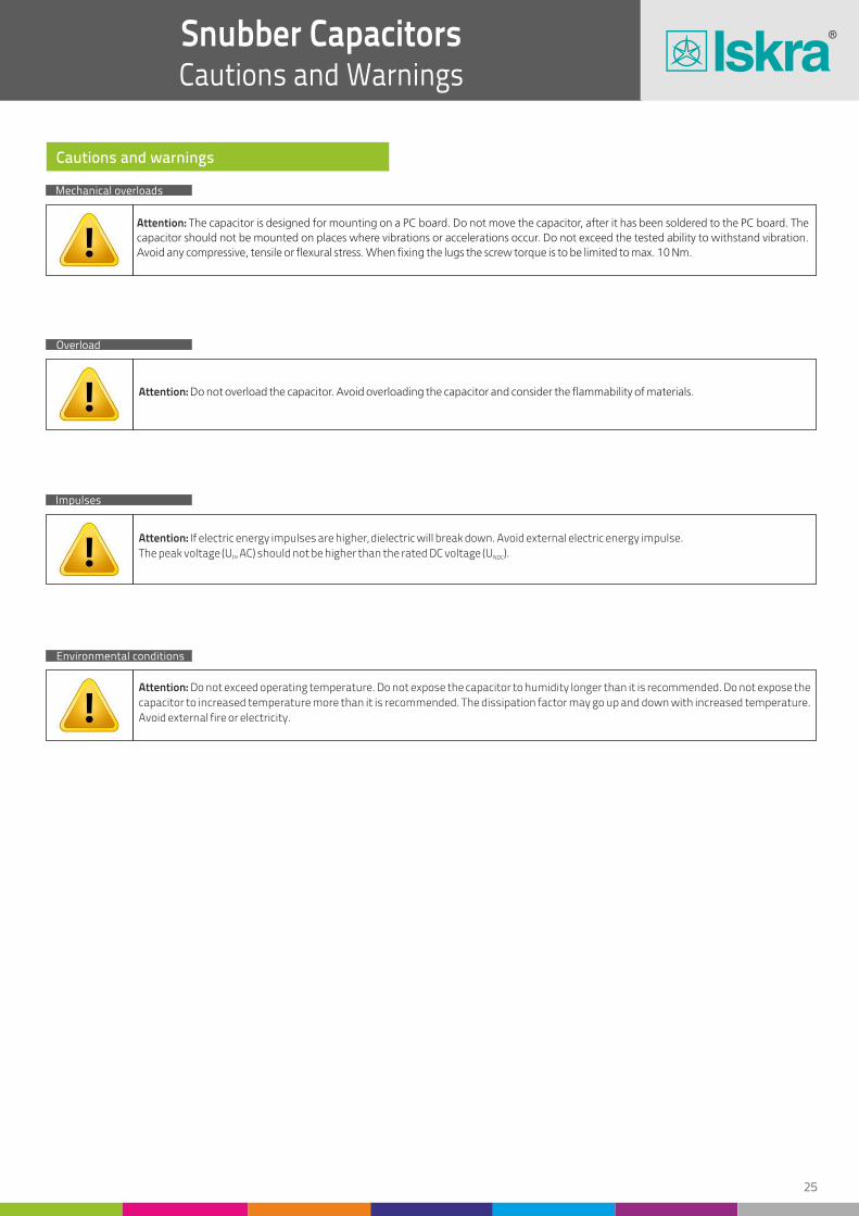
24 25
Snubber CapacitorsApplications
Snubber CapacitorsCautions and Warnings
WIND PLANTS
WELDING EQUIPMENT
UPS SYSTEMS
HYBRID VEHICLES
SOLAR POWER PLANTS
FREQUENCY INVERTERS
DC (AC)/AC (DC)inverter
IGBT module
DC/ACinverter
DC/ACinverter
DC (AC)/AC (DC)inverter
DC (AC)/AC (DC)inverter
Cautions and warnings
Mechanical overloads
Overload
Impulses
Environmental conditions
Attention: The capacitor is designed for mounting on a PC board. Do not move the capacitor, after it has been soldered to the PC board. The capacitor should not be mounted on places where vibrations or accelerations occur. Do not exceed the tested ability to withstand vibration. Avoid any compressive, tensile or flexural stress. When fixing the lugs the screw torque is to be limited to max. 10 Nm.
Attention: Do not overload the capacitor. Avoid overloading the capacitor and consider the flammability of materials.
Attention: If electric energy impulses are higher, dielectric will break down. Avoid external electric energy impulse.
The peak voltage (U , AC) should not be higher than the rated DC voltage (U ).P NDC
Attention: Do not exceed operating temperature. Do not expose the capacitor to humidity longer than it is recommended. Do not expose the
capacitor to increased temperature more than it is recommended. The dissipation factor may go up and down with increased temperature.
Avoid external fire or electricity.
Snubber capacitors Dimensions
DC link capacitors and snubbers

26 27
AC/DC General Purpose CapacitorsType KNI5048
AC/DC General Purpose CapacitorsType KNI5048
Applications
Features
Construction
Reference standard
Metallized polypropylene AC and DC capacitors are used for power electronic applications with high current and harmonics distortion with long life expectancy.
Inverter
Filtering
Switching
AC/DC voltage
Self-healing properties
High reliabilty
Cylindrical aluminium case with plastic self-extinguishing sealing cover
Overpressure disconnector
Tinned brass screw
Dielectric: polypropylene film
Capacitor electrodes: Vacuum-deposited : metal layers
Casing: cylindrical aluminium case with plastic self-extinguishing sealing cover
Tinned brass screw
Specifications
Rated capacitance
Capacitance tolerance
Rated voltage (U ) rms
Operating temperature range
Climatic category
Dissipation factors at 1 kHz
Test voltage terminal to terminal
Test voltage (terminal to case)
Life expectancy
Failure quota
10 mF - 600 mF
± 5 %, ± 10 %
250 V AC, 330 V AC, 480 V AC
-40 °C to +85 °C
40/070/56 according to IEC 60068
-4 tgd ≤ 10 x 10 at 100 Hz
1.5 x U , 10 srms
3 kV, 50 Hz, 2 s
100 000 hours @Ths ≤70 °C-9<300 x 10 components hour
IEC 61071
Internal construction
First contact layer
Second contact layer
Polypropylene film dielectric
Design 1KNI5048
D50 mm to D75 mm
Design 2KNI5048D85 mm
Metal-sprayed contact layers
Metallized layer
Terminations
P ±1
D ±1
D ±1
H ±
2
H ±
2
H1 ±
2
H1 ±
2
M
M1
M1
M
L
L
P ±1
Snubber capacitors Dimensions
DC link capacitors and snubbers

28 29
AC/DC General Purpose CapacitorsType KNI5048
AC/DC General Purpose CapacitorsApplications
30
25
10
50
40
20
70
60
30
100
75
40
150
100
60
175
150
80
200
250
100
300
400
130
200
500
22
22
22
22
22
25
25
25
25
25
25
25
25
25
30
25
30
35
35
45
30
50
50
35
50
50
0.75
0.75
0.4
1.25
1.2
0.8
1.75
1.5
1.2
2.5
1.5
1.6
2.25
2
2.1
2.62
2.25
2
3
3.75
2
3.6
4.8
2.66
4
5
25
30
40
25
30
40
25
25
40
25
20
40
15
20
35
15
15
25
15
15
20
12
12
20
20
10
24
24
24
24
24
24
24
24
24
24
24
24
24
24
28
24
28
28
28
34
28
28
34
34
34
34
6
6
6
6
6
6
6
6
6
6
6
6
6
6
10
6
10
10
10
10
10
10
10
10
10
10
22
22
22
22
22
22
22
22
22
22
22
22
22
22
34
22
34
34
34
35
34
34
35
35
35
35
12
12
12
12
12
12
12
12
12
12
12
12
12
12
12
12
12
12
12
12
12
12
12
12
12
12
12
12
12
12
12
12
12
12
12
12
12
12
12
12
16
12
16
16
16
16
16
16
16
16
16
16
50 x 80
50 x 80
50 x 80
50 x 93
50 x 93
60 x 80
60 x 80
60 x 105
60 x 105
60 x 105
60 x 105
60 x 130
60 x 130
60 x 130
75 x 135
60 x 155
75 x 135
75 x 160
75 x 135
85 x 200
75 x 195
75 x 160
85 x 250
85 x 200
85 x 250
85 x 250
Capacitance range
U = 250 V AC / U = 400 V DCrms NDC
U = 330 V AC / U = 600 V DCrms NDC
U = 480 V AC / U = 850 V DCrms NDC
Imax
Imax
Imax
C N
C N
C N
H1
H1
H1
M
M
M
P
P
P
M1
M1
M1
L
L
L
(mm)
(mm)
(mm)
(mm)
(mm)
(mm)
(mm)
(mm)
(mm)
(mm)
(mm)
(mm)
(mm)
(mm)
(mm)
(µF)
(µF)
(µF)
(A)
(A)
(A)
(kA)
(kA)
(kA)
Î
Î
Î
dU/dt
dU/dt
dU/dt
(V/µs)
(V/µs)
(V/µs)
(mm)
(mm)
(mm)
D x H
D x H
D x H
40
30
15
60
50
25
80
70
35
130
80
50
150
100
70
200
200
90
250
300
100
150
250
400
600
22
22
22
25
22
25
25
25
25
25
25
25
35
30
30
25
40
35
40
50
35
50
50
50
50
1
0.9
0.6
1.5
1.25
1
2
1.4
1.4
1.95
1.6
2
2.25
1.5
2.1
3
3
2.25
3
4.5
2.5
3
3.75
4.8
6
25
30
40
25
25
40
25
20
40
15
20
40
15
15
30
15
15
25
12
15
25
20
15
12
10
24
24
24
24
24
24
24
24
24
24
24
24
28
28
28
24
28
28
28
34
34
34
34
34
34
6
6
6
6
6
6
6
6
6
6
6
6
10
10
10
6
10
10
10
10
10
10
10
10
10
22
22
22
22
22
22
22
22
22
22
22
22
34
34
34
22
34
34
34
35
35
35
35
35
35
12
12
12
12
12
12
12
12
12
12
12
12
12
12
12
12
12
12
12
12
12
12
12
12
12
12
12
12
12
12
12
12
12
12
12
12
12
16
16
16
12
16
16
16
16
16
16
16
16
16
50 x 80
50 x 80
55 x 80
60 x 80
55 x 93
60 x 93
60 x 93
60 x 105
60 x 105
60 x 130
60 x 105
60 x 130
75 x 110
75 x 110
75 x 135
60 x 155
75 x 155
75 x 160
75 x 160
85 x 200
85 x 175
85 x 200
85 x 300
85 x 200
85 x 250
Notes: Other values and dimensions available on request.
WELDING EQUIPMENT
UPS SYSTEMS
SOLAR POWER PLANTS
FREQUENCY INVERTERS
WIND PLANTS
DC/ACinverter
DC/ACinverter
DC (AC)/AC (DC)inverter
inverterDC (AC)/AC (DC)
General characteristics
Snubber capacitors Dimensions
DC link capacitors and snubbers

30 31
AC/DC General Purpose CapacitorsConnection and Mounting Instructions
AC/DC General Purpose CapacitorsLifetime Expectancy
Connection
Mounting
Earthing
Safe operation of the capacitors can be expected only if all electrical and thermal specifications as stated on the label, in the data sheets or catalogues and the
following instructions are strictly observed. The manufacturer does not accept responsibility for any damage that could arise due to non-observance.
Use the appropriate tab connectors to connect the cables of the capacitors.
Do not solder leads to the terminals.
Do not bend or turn or move in any other way the connecting terminals and the tab connectors.
Do not use heavy or sharp objects and tools on the bordering or the connecting terminals.
Connection at threaded studs should be made between two nuts. During the connection the lower nut should be backed up to avoid any transmission of the
torque.
Permitted torque for screw connections:
Can be mounted in any position.
The capacitor has to be installed in such a way as to avoid any mechanical damage and dents in the aluminium.
Capacitors with overpressure safety device should be connected with sufficiently flexible leads in order to enable proper functioning of the mechanism. Above
the terminals leave enough space for expansion of the capacitor case.
Leave a minimum distance of 15 mm of free space above each capacitor.
Connect these capacitors by using only flexible cables or elastic copper bands.
Capacitors with a metal case must be earthed at the mounting stud.
Permitted torque for studs:
M8 – 5 Nm
M12 – 12 Nm
TO PREVENT BREAKING AT TIGHTENING
ALWAYS USE TWO WRENCHES
WARNING: safe connection
Expected lifetime curves
Hot spot
temperature
85 °C
60 °C
70 °C
50 °C
Voltage ratio (U/U )rms
Exp
ect
ed
life
tim
e (h
)
1000000
100000
10000
1000
100
0.75 0.85 0.95 1.05 1.15 1.25 1.35 1.45 1.55 1.65
M6 - 5 Nm
M8 - 6 Nm
M10 - 10 Nm
Snubber capacitors Dimensions
DC link capacitors and snubbers

32 33
AC/DC General Purpose CapacitorsCautions and Warnings
AC Filtering CapacitorsType KNB1910, KNB1914
Cautions and warnings
Safety
Thermal load
Storage and operating conditions
Mechanichal protection
Overpressure disconnector
Attention: In case of dents of more than 1 mm in depth or any other mechanical damage, capacitors must not be used at all. This also applies
to cases of leakage. To ensure the full functionality of the overpressure disconnector, elastic elements must not be hindered and a
minimum space of 15 mm has to be kept above each capacitor. Check tightness of the connections/terminals periodically. The energy
stored in capacitors may be lethal. To prevent any chance of shock, discharge and short circuit the capacitor before handling. Failure to
follow cautions may result, in the worst case, in premature failures, bursting and fire. Iskra, d.d. is not responsible for any damage caused to
people or things and resulting from an improper installation or a misapplication of capacitors.
Attention: Electrical or mechanical misapplication of capacitors may be hazardous. Personal injury or property damage may result from
bursting of the capacitor or from the expulsion of oil ormelted material due to mechanical disruption of the capacitor. Ensure good, effective
grounding for capacitor enclosures. Observe appropriate safety precautions during operation (self-recharging phenomena and high energy
contained in the capacitor). Handle capacitors carefully, because even after the disconnection they may still be charged. The terminals of
capacitors, connected bus bars and cables as well as other devices may also be energized. Follow good engineering practice.
Attention: After installation of the capacitor it is necessary to verify that maximum hot spot temperature does not exceed during extreme
service conditions.
Attention: Do not use or store capacitors in corrosive atmosphere, especially where chloride gas, sulfide gas, acid, alkali, salt or the like are
present. In dusty environments, it is required to perform regular maintenance and proper cleaning, especially of the terminals, to avoid
conductive path between phases and/or phases and ground. The maximum storage temperature is 85 °C.
Attention: The capacitor has to be installed in such a way as to avoid any mechanical damage and dents in the aluminium.
Attention: To ensure full functionality of an overpressure disconnector, the following must be observed: The elastic elements must be
hindered, i.e.: connecting lines must be flexible leads (cables); there must be enough space for expansion above the connections; folding
crimps must not be retained by clamps; stress parameters of the capacitor must followIEC 61071 specification.
Reference standard
IEC 61071
Applications
Features
Input/output AC filters for power converters
Switching mode power supplies (SMPS)
Solar power plants
Wind plants
Motor drives
Induction heaters
Frequency inverters
Uninterruptible power supplies (UPS)
Self-healing properties
High ripple current
High reliability
Low losses
Small dimensions
Designed for PCB mounting
Specifications
Rated capacitance
Capacitance tolerance
Rated voltage UN
Operating temperature range
Climatic category
Life expectancy
Rated temperature
Max. operating temperature (case)
0.1 µF to 80 µF
± 5 %, ± 10 %
250 V AC, 300 V AC, 350 V AC, 400 V AC, 440 V AC
-40 °C to 85 °C
40/85/56 acc. to IEC 60068-1
≥60 000 hours at UN
85°C
105 °C
Snubber capacitors Dimensions
DC link capacitors and snubbers
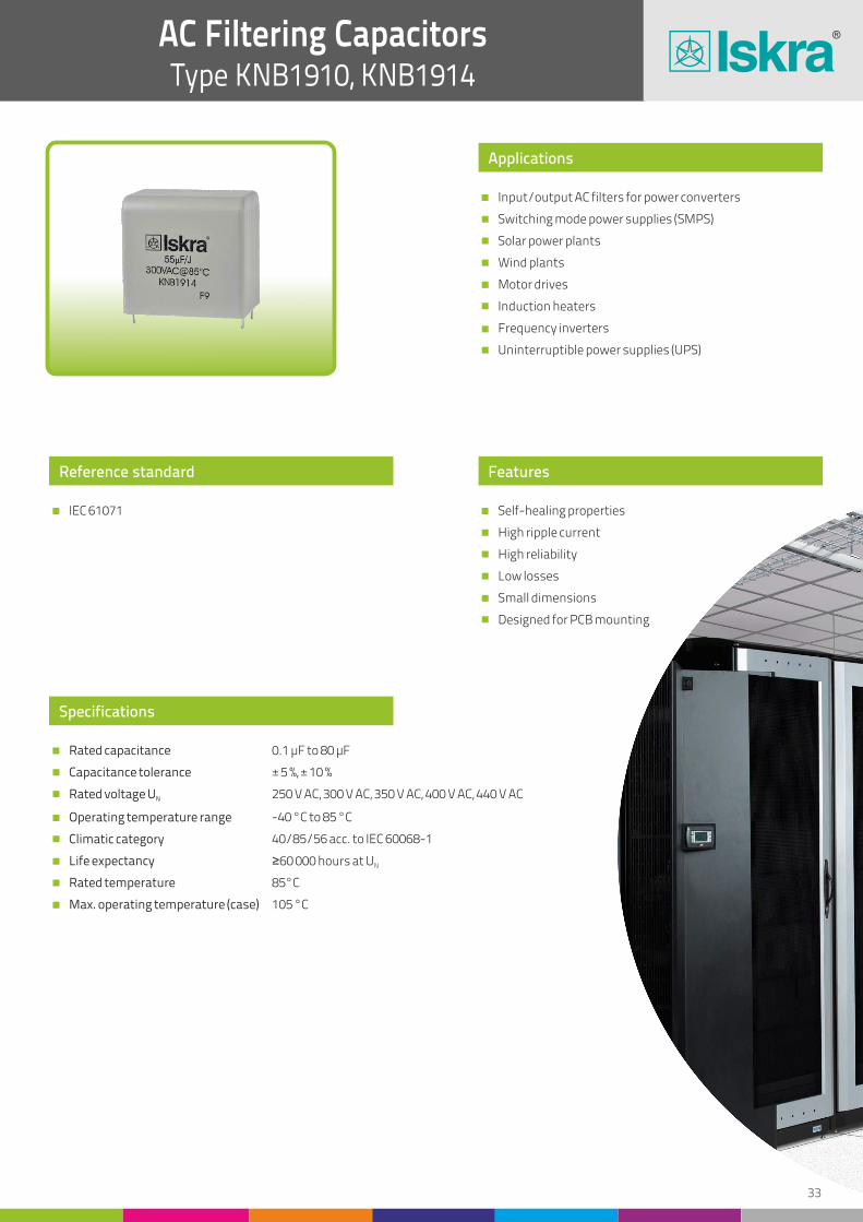
32 33
AC/DC General Purpose CapacitorsCautions and Warnings
AC Filtering CapacitorsType KNB1910, KNB1914
Cautions and warnings
Safety
Thermal load
Storage and operating conditions
Mechanichal protection
Overpressure disconnector
Attention: In case of dents of more than 1 mm in depth or any other mechanical damage, capacitors must not be used at all. This also applies
to cases of leakage. To ensure the full functionality of the overpressure disconnector, elastic elements must not be hindered and a
minimum space of 15 mm has to be kept above each capacitor. Check tightness of the connections/terminals periodically. The energy
stored in capacitors may be lethal. To prevent any chance of shock, discharge and short circuit the capacitor before handling. Failure to
follow cautions may result, in the worst case, in premature failures, bursting and fire. Iskra, d.d. is not responsible for any damage caused to
people or things and resulting from an improper installation or a misapplication of capacitors.
Attention: Electrical or mechanical misapplication of capacitors may be hazardous. Personal injury or property damage may result from
bursting of the capacitor or from the expulsion of oil ormelted material due to mechanical disruption of the capacitor. Ensure good, effective
grounding for capacitor enclosures. Observe appropriate safety precautions during operation (self-recharging phenomena and high energy
contained in the capacitor). Handle capacitors carefully, because even after the disconnection they may still be charged. The terminals of
capacitors, connected bus bars and cables as well as other devices may also be energized. Follow good engineering practice.
Attention: After installation of the capacitor it is necessary to verify that maximum hot spot temperature does not exceed during extreme
service conditions.
Attention: Do not use or store capacitors in corrosive atmosphere, especially where chloride gas, sulfide gas, acid, alkali, salt or the like are
present. In dusty environments, it is required to perform regular maintenance and proper cleaning, especially of the terminals, to avoid
conductive path between phases and/or phases and ground. The maximum storage temperature is 85 °C.
Attention: The capacitor has to be installed in such a way as to avoid any mechanical damage and dents in the aluminium.
Attention: To ensure full functionality of an overpressure disconnector, the following must be observed: The elastic elements must be
hindered, i.e.: connecting lines must be flexible leads (cables); there must be enough space for expansion above the connections; folding
crimps must not be retained by clamps; stress parameters of the capacitor must followIEC 61071 specification.
Reference standard
IEC 61071
Applications
Features
Input/output AC filters for power converters
Switching mode power supplies (SMPS)
Solar power plants
Wind plants
Motor drives
Induction heaters
Frequency inverters
Uninterruptible power supplies (UPS)
Self-healing properties
High ripple current
High reliability
Low losses
Small dimensions
Designed for PCB mounting
Specifications
Rated capacitance
Capacitance tolerance
Rated voltage UN
Operating temperature range
Climatic category
Life expectancy
Rated temperature
Max. operating temperature (case)
0.1 µF to 80 µF
± 5 %, ± 10 %
250 V AC, 300 V AC, 350 V AC, 400 V AC, 440 V AC
-40 °C to 85 °C
40/85/56 acc. to IEC 60068-1
≥60 000 hours at UN
85°C
105 °C
Snubber capacitors Dimensions
DC link capacitors and snubbers

34 35
AC Filtering CapacitorsType KNB1910, KNB1914
AC Filtering CapacitorsType KNB1910, KNB1914
1 1
3 3
5 4
7 6
9 8
12 10
8 5.6
10 7
12 8
20 10
25 15
35 20
40 25
50 35
60 45
70 55
80
32.0 32.0
32.0 32.0
32.0 32.0
32.0 32.0
32.0 32.0
32.0 32.0
42.0 42.0
42.0 42.0
42.0 42.0
42.0 42.0
42.0 42.0
42.0 42.0
57.5 57.5
57.5 57.5
57.5 57.5
57.5 57.5
57.5
19.0 19.0
21.0 24.5
24.5 26.5
28.0 33.0
33.0 40.0
35.5 40.0
27.0 27.0
31.0 31.0
31.0 38.0
43.0 38.0
43.0 43.0
50.0 45.0
45.0 45.0
50.0 50.0
50.0 55.0
50.0 55.0
55.0
10.0 10.0
12.0 15.0
15.0 17.0
18.0 20.0
20.0 25.0
24.0 25.0
16.0 16.0
18.0 18.0
18.0 21.0
28.0 21.0
28.0 28.0
36.0 30.0
30.0 30.0
35.0 35.0
35.0 40.0
35.0 40.0
40.0
27.5 27.5
27.5 27.5
27.5 27.5
27.5 27.5
27.5 27.5
27.5 27.5
37.5 37.5
37.5 37.510.2 10.2
10.2 10.2
10.2 10.2
10.2 10.2
37.5 37.5
37.5 37.5
37.5 37.5
37.5 37.5
52.5 52.5
52.5 52.5
52.5 52.5
52.5 52.5
52.5
10 10
10 10
10 10
10 10
10 10
10 10
10 10
10 10
10 10
10 10
10 10
15 15
25 15
25 20
30 20
30 20
30
30.0 30.0
17.1 14.0
11.0 11.0
8.2 8.3
6.5 6.6
4.9 5.5
15.0 15.4
12.3 13.2
10.8 12.0
6.6 10.0
5.5 6.8
4.5 5.3
4.7 6.8
3.8 5.0
3.2 4.0
2.9 3.3
2.7
4.0 4.0
5.8 7.1
8.0 8.4
10.0 10.9
12.3 13.8
15.2 15.1
7.9 7.8
9.4 9.0
10.0 10.3
14.1 11.3
15.5 13.9
19.1 16.4
19.2 16.0
22.9 20.0
25.0 22.9
26.2 25.3
27.9
32 40
32 40
32 40
32 40
32 40
32 40
23 28
23 28
23 28
23 28
23 28
23 28
15 19
15 19
15 19
15 19
15
32 40
96 120
160 160
224 240
288 320
384 400
184 157
230 196
276 224
460 280
575 420
805 560
600 475
750 665
900 855
1050 1045
1200
– –
– –
– –
– –
– –
– –
– –
Capacitance range Capacitance range
U @ 85 °C = 250 V AC, U @ 85 °C = 600 V DCN NDC U @ 85 °C = 300 V AC, U @ 85 °C = 750 V DCN NDC
L L
(1) C N
(1) C N
(2)Dimensions (mm) (2)Dimensions (mm) (3)tan( )@1kHz δ (3)tan( )@1kHz δ(4)ESR@10 kHz (4)ESR@10 kHz (5)I @10 kHz max
(5)I @10 kHz max(dU/dt)max (dU/dt)maxÎ Î
-4(x10 ) -4(x10 )(mW) (mW)(A) (A)(µF) (µF)(V/µs) (V/µs)(A) (A)H HW WP PP1 P1
2 2
4 3.3
6 5
8 7
10 9
15 5
9 6
11 7.5
15 9
22 12
30 16
40 25
45 30
55 40
65 50
75
32.0 32.0
32.0 32.0
32.0 32.0
32.0 32.0
32.0 32.0
32.0 42.0
42.0 42.0
42.0 42.0
42.0 42.0
42.0 42.0
42.0 42.0
42.0 42.0
57.5 57.5
57.5 57.5
57.5 57.5
57.5
19.0 21.0
22.0 24.5
26.5 32.0
32.0 33.5
35.0 40.0
40.0 27.0
31.0 31.0
31.0 38.0
38.0 38.0
43.0 43.0
45.0 43.0
50.0 50.0
45.0 50.0
50.0 50.0
50.0 55.0
55.0
10.0 12.0
13.0 15.0
17.0 18.0
18.0 24.0
20.0 25.0
25.0 16.0
18.0 18.0
18.0 21.0
21.0 21.0
28.0 28.0
30.0 28.0
36.0 36.0
30.0 35.0
35.0 35.0
35.0 40.0
40.0
27.5 27.5
27.5 27.5
27.5 27.5
27.5 27.5
27.5 27.5
27.5 37.5
37.5 37.5
37.5 37.5
37.5 37.5
37.5 37.5
37.5 37.5
37.5 37.5
52.5 52.5
52.5 52.5
52.5 52.5
52.5
10 10
10 10
10 10
10 10
10 10
10 10
10 10
10 10
10 10
10 10
15 10
15 15
25 15
25 20
30 20
30
24.3 19.8
13.5 13.0
9.5 9.5
7.3 7.3
5.9 6.0
4.0 17.0
13.5 14.5
11.4 12.5
8.7 11.0
6.0 8.5
5.0 6.5
4.0 4.3
4.2 5.8
3.5 4.4
3.0 3.6
2.8
4.5 5.3
6.7 7.3
9.0 9.7
11.1 12.4
13.2 14.4
17.8 7.4
8.9 8.6
9.7 10.1
12.1 10.7
14.8 12.4
16.9 14.2
20.2 19.5
20.3 18.5
23.9 19.9
25.8 24.2
27.4
32 40
32 40
32 40
32 40
32 40
32 28
23 28
23 28
23 28
23 28
23 28
23 28
15 19
15 19
15 19
15
64 80
128 132
192 200
256 280
320 360
480 140
207 168
253 210
345 252
506 336
690 448
920 700
675 570
825 760
975 950
1125
– –
– –
– –
– –
– –
– –
– –
10.2 10.2
10.2 10.2
10.2 10.2
10.2/20.3 10.2
10.2/20.3 10.2/20.3
20.3 20.3
20.3 20.3
20.3 20.3
20.3
10.2/20.3 10.2/20.3
20.3 20.3
20.3 20.3
20.3 20.3
20.3 20.3
20.3
General characteristics General characteristics
Notes:Notes: (1) Capacitance value measured at 1 kHz. Intermediate capacitance values available on request.(1) Capacitance value measured at 1 kHz. Intermediate capacitance values available on request.
(3) Maximum tan( ) values.δ(3) Maximum tan( ) values.δ
(2) Nominal dimensions.(2) Nominal dimensions.
(4) Typical equivalent series resistance at 10 kHz.(4) Typical equivalent series resistance at 10 kHz. (5) Maximum r.m.s. current at 10 kHz, = 70°C for ≤ 20°C.amb caseθ Δθ(5) Maximum r.m.s. current at 10 kHz, = 70°C for ≤ 20°C.amb caseθ Δθ
Snubber capacitors Dimensions
DC link capacitors and snubbers

36 37
AC Filtering CapacitorsType KNB1910, KNB1914
AC Filtering CapacitorsType KNB1910, KNB1914
1 0.47
2 0.68
3 1
4 2
6 3
4 5
5 3
7 4
9 6
12 7.5
15 9
20 12
20 13
24 15
26 18
35 22
26
32.0 32.0
32.0 32.0
32.0 32.0
32.0 32.0
32.0 32.0
42.0 32.0
42.0 42.0
42.0 42.0
42.0 42.0
42.0 42.0
42.0 42.0
42.0 42.0
57.5 57.5
57.5 57.5
57.5 57.5
57.5 57.5
57.5
19.0 16.0
24.5 19.0
28.0 21.0
32.0 26.5
40.0 33.0
27.0 40.0
31.0 31.0
38.0 38.0
43.0 43.0
43.0 43.0
45.0 45.0
50.0 50.0
45.0 45.0
50.0 45.0
50.0 50.0
55.0 55.0
55.0
10.0 7.5
15.0 10.0
18.0 12.0
18.0 17.0
25.0 20.0
16.0 25.0
18.0 18.0
21.0 21.0
28.0 28.0
28.0 28.0
30.0 30.0
36.0 36.0
30.0 30.0
35.0 30.0
35.0 35.0
40.0 40.0
40.0
27.5 27.5
27.5 27.5
27.5 27.5
27.5 27.5
27.5 27.5
37.5 27.5
37.5 37.5
37.5 37.510.2
10.2
10.2
10.2 10.2
10.2 10.2
37.5 37.5
37.5 37.5
37.5 37.5
37.5 37.5
52.5 52.5
52.5 52.5
52.5 52.5
52.5 52.5
52.5
10 10
10 10
10 10
10 10
10 10
10 10
10 10
10 10
10 10
10 10
15 10
15 15
15 15
20 20
20 20
20 20
20
30.0 45.0
17.0 38.0
12.5 28.0
9.8 16.0
7.5 11.5
19.0 7.5
16.0 19.0
11.8 15.0
9.5 10.3
7.3 8.6
6.0 7.6
4.5 6.0
7.9 8.2
6.7 7.3
6.3 6.3
4.8 5.2
4.4
4.0 2.9
6.4 3.6
8.1 4.5
9.6 6.9
12.9 9.2
7.0 12.9
8.2 7.5
10.4 9.2
11.8 11.3
13.4 12.4
15.4 13.7
19.1 16.5
14.8 14.6
17.3 15.4
17.8 17.8
20.9 20.1
21.9
50 57
50 57
50 57
50 57
50 57
35 57
35 40
35 40
35 40
35 40
35 40
35 40
23 27
23 27
23 27
23 27
27
50 27
100 39
150 57
200 114
300 171
140 285
175 120
245 160
315 240
420 300
525 360
700 480
460 351
552 405
598 486
805 594
702
– –
– –
– –
– –
– –
– –
–
Capacitance range Capacitance range
U @ 85 °C = 350 V AC, U @ 85 °C = 900 V DCN NDC U @ 85 °C = 400 V AC, U @ 85 °C = 1000 V DCN NDC
L L
(1) C N
(1) C N
(2)Dimensions (mm) (2)Dimensions (mm) (3)tan( )@1kHz δ (3)tan( )@1kHz δ(4)ESR@10 kHz (4)ESR@10 kHz (5)I @10 kHz max
(5)I @10 kHz max(dU/dt)max (dU/dt)maxÎ Î
-4(x10 ) -4(x10 )(mW) (mW)(A) (A)(µF) (µF)(V/µs) (V/µs)(A) (A)H HW WP PP1 P1
1.2 0.56
2.2 0.82
3.3 1.5
5 2.2
7 3.5
5 2.7
6 3.5
8 5
10 7
14 8
18 10
18 13
22 14
25 16
30 20
25
32.0 32.0
32.0 32.0
32.0 32.0
32.0 32.0
32.0 32.0
42.0 42.0
42.0 42.0
42.0 42.0
42.0 42.0
42.0 42.0
42.0 42.0
57.5 42.0
57.5 57.5
57.5 57.5
57.5 57.5
57.5
21.0 17.0
24.5 21.0
32.0 24.5
40.0 26.5
40.0 35.0
31.0 27.0
38.0 31.0
38.0 38.0
43.0 43.0
45.0 43.0
50.0 45.0
45.0 50.0
50.0 45.0
50.0 50.0
55.0 50.0
55.0
12.0 9.0
15.0 12.0
18.0 15.0
25.0 17.0
25.0 20.0
18.0 16.0
21.0 18.0
21.0 21.0
28.0 28.0
30.0 28.0
36.0 30.0
30.0 36.0
35.0 30.0
35.0 35.0
40.0 35.0
40.0
27.5 27.5
27.5 27.5
27.5 27.5
27.5 27.5
27.5 27.5
37.5 37.5
37.5 37.5
37.5 37.5
37.5 37.5
37.5 37.5
37.5 37.5
52.5 37.5
52.5 52.5
52.5 52.5
52.5 52.5
52.5
10 10
10 10
10 10
10 10
10 10
10 10
10 10
10 10
10 10
15 10
15 15
15 15
20 15
20 20
20 20
20
25.0 40.0
16.0 33.0
11.5 20.0
8.5 15.0
6.8 10.5
16.0 20.0
13.5 17.0
10.5 12.0
8.8 9.0
6.5 8.3
5.0 7.0
8.7 5.6
7.2 7.7
6.5 7.0
5.5 5.7
4.6
4.8 3.3
6.6 4.1
8.8 5.9
12.1 7.2
13.6 9.8
8.2 6.8
9.7 8.0
11.0 10.3
12.2 12.1
14.8 12.6
18.1 14.3
14.1 17.1
16.6 15.0
17.5 16.9
19.6 18.7
21.4
50 57
50 57
50 57
50 57
50 57
35 40
35 40
35 40
35 40
35 40
35 40
23 40
23 27
23 27
23 27
27
60 32
110 47
165 86
250 125
350 200
175 108
210 140
280 200
350 280
490 320
630 400
414 520
506 378
575 432
690 540
675
– –
– –
– –
– –
– –
– –
10.2 10.2
10.2 10.2
10.2
10.2/20.3
10.2/20.3
10.2/20.3
10.2/20.3
20.3
20.3
20.3
20.3 20.3
20.3 20.3
20.3
10.2/20.3
10.2/20.3
10.2/20.3
10.2/20.3
20.3 20.3
20.3 20.3
20.3 20.3
20.3 20.3
20.3
10.2 10.2
General characteristics General characteristics
Notes:
Notes:
(1) Capacitance value measured at 1 kHz. Intermediate capacitance values available on request.
(1) Capacitance value measured at 1 kHz. Intermediate capacitance values available on request.
(3) Maximum tan( ) values.δ
(3) Maximum tan( ) values.δ(2) Nominal dimensions.
(2) Nominal dimensions.
(4) Typical equivalent series resistance at 10 kHz.
(4) Typical equivalent series resistance at 10 kHz.
(5) Maximum r.m.s. current at 10 kHz, = 70°C for ≤ 20°C.amb caseθ Δθ
(5) Maximum r.m.s. current at 10 kHz, = 70°C for ≤ 20°C.amb caseθ Δθ
Snubber capacitors Dimensions
DC link capacitors and snubbers

38 39
AC Filtering CapacitorsType KNB1910, KNB1914
AC Filtering CapacitorsApplications
0.1
0.22
0.47
0.68
1
2
3
2
3
4
5
6
7
8
10
15
18
32.0
32.0
32.0
32.0
32.0
32.0
32.0
42.0
42.0
42.0
42.0
42.0
42.0
57.5
57.5
57.5
57.5
16.0
17.0
19.0
22.0
24.5
33.0
40.0
31.0
38.0
38.0
43.0
45.0
50.0
45.0
45.0
55.0
55.0
7.5
9.0
10.0
13.0
15.0
20.0
25.0
18.0
21.0
21.0
28.0
30.0
36.0
30.0
30.0
40.0
40.0
27.5
27.5
27.5
27.5
27.5
27.5
27.5
37.5 10.2
10.2
10.2
10.2
37.5
37.5
37.5
37.5
37.5
52.5
52.5
52.5
52.5
10
10
10
10
10
10
10
15
15
15
15
15
15
20
20
20
20
100.0
55.0
35.0
30.0
22.0
13.0
10.0
17.0
12.0
10.5
9.0
7.8
6.9
6.5
5.8
4.1
3.9
2.0
2.8
3.7
4.5
5.6
8.7
11.2
8.0
10.3
11.0
12.1
13.5
15.4
16.4
17.3
22.7
23.2
150
150
150
150
150
150
150
100
100
100
100
100
100
65
65
65
65
15
33
71
102
150
300
450
200
300
400
500
600
700
520
650
975
1170
–
–
–
–
–
–
–
Capacitance range
U @ 85 °C = 440 V AC, U @ 85 °C = 1100 V DCN NDC
L
(1) C N
(2)Dimensions (mm) (3)tan( )@1kHz δ(4)ESR@10 kHz (5)I @10 kHz max
(dU/dt)max Î-4(x10 ) (mW) (A)(µF) (V/µs) (A)H W P P1
0.15
0.33
0.56
0.82
1.5
2.2
1.5
2.2
3.3
4.7
5.6
6.8
8
9
12
16
32.0
32.0
32.0
32.0
32.0
32.0
42.0
42.0
42.0
42.0
42.0
42.0
42.0
57.5
57.5
57.5
16.0
17.0
21.0
24.5
28.0
35.0
27.0
31.0
38.0
43.0
43.0
45.0
50.0
45.0
50.0
55.0
7.5
9.0
12.0
15.0
18.0
20.0
16.0
18.0
21.0
28.0
28.0
30.0
36.0
30.0
35.0
40.0
27.5
27.5
27.5
27.5
27.5
27.5
37.5
37.5
37.5
37.5
37.5
37.5
37.5
52.5
52.5
52.5
10
10
10
10
10
10
15
15
15
15
15
15
15
20
20
20
70.0
45.0
33.0
25.0
16.0
12.0
21.0
16.0
11.0
9.5
8.2
7.0
6.2
6.2
5.0
4.0
2.4
3.1
4.1
5.1
7.2
9.2
6.7
8.2
10.7
11.8
12.7
14.3
16.3
16.7
20.0
22.9
150
150
150
150
150
150
100
100
100
100
100
100
100
65
65
65
23
50
84
123
225
330
150
220
330
470
560
680
800
585
780
1040
–
–
–
–
–
–
–
10.2
10.2
10.2
10.2
20.3
20.3
20.3
10.2/20.3
10.2/20.3
10.2/20.3
10.2/20.3
20.3
20.3
20.3
20.3
WIND PLANTS
WELDING EQUIPMENT
UPS SYSTEMS
HYBRID VEHICLES
SOLAR POWER PLANTS
FREQUENCY INVERTERS
DC (AC)/AC (DC)inverter
IGBT module
DC/ACinverter
DC/ACinverter
DC (AC)/AC (DC)inverter
DC (AC)/AC (DC)inverter
Dimensions
KNB1910 - 2 pins KNB1914 - 4 pins
L L W
H
W
P
27.5
37.5 20.3
0.8
1 or 1.2
L + 0.5
L + 0.5
H + 0.2
H + 0.5
W + 0.5
W + 0.5
– –±0.5
±0.5 ±0.5
±0.05
±0.05
PP1
4 o
r 6
4 o
r 6H
d d
Terminal dimensions Max. box dimensions
P(mm)
P1(mm)
d(mm)
Lmax
(mm)Hmax
(mm)Wmax
(mm)Tolerance
(mm)Tolerance
(mm)Tolerance
(mm)
37.5 10.2 1 or 1.2 L + 0.5 H + 0.5 W + 0.5±0.5 ±0.5 ±0.05
52.5 20.3 1.2 L + 1.0 H + 1.0 W + 1.0±0.5 ±0.5 ±0.05
General characteristics
Notes:(1) Capacitance value measured at 1 kHz. Intermediate capacitance values available on request.
(3) Maximum tan( ) values.δ
(2) Nominal dimensions.
(4) Typical equivalent series resistance at 10 kHz.(5) Maximum r.m.s. current at 10 kHz, = 70°C for ≤ 20°C.amb caseθ Δθ
Snubber capacitors Dimensions
DC link capacitors and snubbers

40
AC Filtering CapacitorsConstruction, Cautions and Warnings
Cautions and warnings
Mechanical overloads
Overload
Impulses
Environmental conditions
Attention: The capacitor is designed for mounting on a PC board. Do not move the capacitor, after it has been soldered to the PC board. The
capacitor should not be mounted on places where vibrations or accelerations occur. Do not exceed the tested ability to withstand vibration.
Avoid any compressive, tensile or flexural stress.
Attention: Do not overload the capacitor. Avoid overloading the capacitor and consider the flammability of materials.
Attention: If electric energy impulses are higher, dielectric will break down. Avoid external electric energy impulse.
The peak voltage (U , AC) should not be higher than the rated DC voltage (U ).P NDC
Attention: Do not exceed operating temperature. Do not expose the capacitor to humidity longer than it is recommended. Do not expose the
capacitor to increased temperature more than it is recommended. The dissipation factor may go up and down with increased temperature.
Avoid external fire or electricity.
Internal construction
First contact layer
Second contact layer
Polypropylene film dielectric
Metal-sprayed contact layers
Metallized layer
Snubber capacitors Dimensions
DC link capacitors and snubbers

Published by Iskra, d.d. • Version 2.0, June 2016
Iskra, d.d.Stegne 21SI-1000 LjubljanaSloveniaPhone.: Fax: [email protected]
+386 1 51 11 532+386 1 51 31 000
Snubber capacitors Dimensions
DC link capacitors and snubbers