Embed Size (px)
Citation preview

OIF CEI-56G Common ElectricalInterfaces
Tom PalkertLuxtera/MoSys
OIF PLL Vice Chair Electrical
Tom PalkertLuxtera/MoSys
OIF PLL Vice Chair Electrical

Outline
Port Density Requirements OIF CEI-56G applications
• USR (die to die in an MCM)• XSR (Chip to optical engine/memory)• VSR (Chip to Pluggable module)• MR (Chip to Chip)• LR (Backplane)
NRZ and PAM4 test and simulation results NRZ vs PAM4 arguments Conclusion
2 FOE 2015
Port Density Requirements OIF CEI-56G applications
• USR (die to die in an MCM)• XSR (Chip to optical engine/memory)• VSR (Chip to Pluggable module)• MR (Chip to Chip)• LR (Backplane)
NRZ and PAM4 test and simulation results NRZ vs PAM4 arguments Conclusion

Port density requirements for Data Centersde
RJ-45 – 48 Channels10GBaseT = 480 Gbps
SFP+ – 48 Channels50G = 2.7 Tbps
Channels/Bandwidth
3 FOE 2015
iPass – 160 Channels
QSFP 144 Channels50G = 7.2 Tbps
CXP – 320 Channels50G = 16 Tbps

OIF CEI Interfaces for 56G
LR
MR
Switch card
XSRUSR
4 FOE 2015
VSR
MRXSR
USR

CEI-56G-USR
Key specificationsfor USR• 10mm trace length• DC coupled• Common clock• Low voltage swing
HOST LSI
PCB
LSI_PKG
HOST LSI
LSI_PKG
Memory IC
MCM with memory IC
5 FOE 2015
Key specificationsfor USR• 10mm trace length• DC coupled• Common clock• Low voltage swing
Optical I/O core
HOST LSI DriverIC
Mod
OpticalI/O
LSI_PKG
Si-photonics chip
PCB
MCM with OPTICAL ENGINE

CEI-56G-XSR
Key specifications for XSR• 50-100mm trace length• DC coupled• Common clock• Low voltage swing
6 FOE 2015
XSR interop points
ASICOptical Engine or Memory device
Optical Fiber
Key specifications for XSR• 50-100mm trace length• DC coupled• Common clock• Low voltage swing

NRZ SIMULATIONS for 56G XSR
7 FOE 2015

PAM4 XSR simulations
RxS eye at slicer(post 3.5dB CTLE)
Tx swing400mVpp
8 FOE 2015
EW = 0.38 UIEH= 45 mV
(for caseIncluding 3dBtotal package losses)
Tx eye atpackage

CEI-56G-VSR
Key specifications for VSR• 100mm trace length• One connector• Uses a test/compliance board to measure host and
module waveformsOptical Module
Module connector
9 FOE 2015
Key specifications for VSR• 100mm trace length• One connector• Uses a test/compliance board to measure host and
module waveforms
Host PCBA
Optical Module
Interoperability point
ChipModule connector
AC couplingcapacitor

CEI-56G-VSR candidate channel
Channel includes:• Package model• RX input termination
capacitance• VSR (QSFP) connector
model
10 FOE 2015
Channel includes:• Package model• RX input termination
capacitance• VSR (QSFP) connector
model

CEI-56G-VSR-NRZ eye diagram
Note: simulations included:- RX jitter and package-3mv rms input noise-TX jitter
11 FOE 2015
Courtesy: MoSys

VSR PAM4 simulation results
12 FOE 2015

VSR NRZ test results
13 FOE 2015
Courtesy Credo Semiconductor

VSR-PAM4 test results
14 FOE 2015

CEI-56G-MR
TX RX
Key specifications for MR• 500mm trace length• Zero or One connector• Compliance uses COM code
15 FOE 2015
Chip to Chip interop points
AC couplingcapacitor
MR

MR channel for NRZ testing
16 FOE 2015
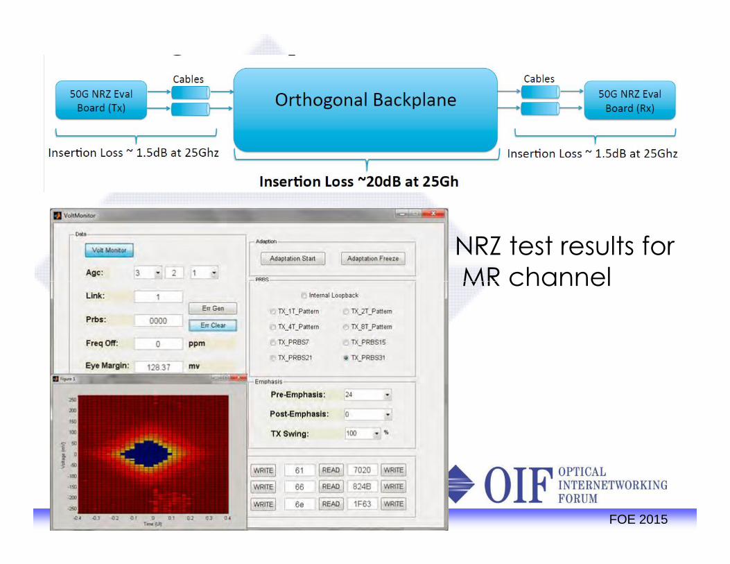
NRZ test results forMR channel
17 FOE 2015
NRZ test results forMR channel

MR measured results PAM4
18 FOE 2015

CEI-56G-LR Key specifications for LR
• 1000mm trace length• Two connectors
19 FOE 2015

LR measured results NRZ
20 FOE 2015
Courtesy: Credo Semiconductor

LR NRZ Measured results
21 FOE 2015
Courtesy:Credo Semiconductor

LR PAM4 Measured ResultsDesign Con 2015 demos
22 FOE 2015
Parthasarathy_3bs_01_0315

Why NRZ over PAM4? PAM4 has a 9dB SNR penalty
• 3 PAM4 eyes in the same voltage swingas 1 NRZ eye
• VSR channel shows an 8-9dB difference
NRZ has more equalization techniques that can be usedbefore we move to PAM4
• Higher gain CTLE• DFE• TX equalization
Low cost/Low loss Printed circuit board materials areavailable
23 FOE 2015
PAM4 has a 9dB SNR penalty• 3 PAM4 eyes in the same voltage swing
as 1 NRZ eye• VSR channel shows an 8-9dB difference
NRZ has more equalization techniques that can be usedbefore we move to PAM4
• Higher gain CTLE• DFE• TX equalization
Low cost/Low loss Printed circuit board materials areavailable

Why PAM4 over NRZ?
As process nodes get smaller density is increasingbut not speed• PAM designs can use lower cost semiconductor
processes PAM operates over legacy channels
• Same baud rate as 28G NRZ Lower loss channels may not require as much
equalization as NRZ
24 FOE 2015
As process nodes get smaller density is increasingbut not speed• PAM designs can use lower cost semiconductor
processes PAM operates over legacy channels
• Same baud rate as 28G NRZ Lower loss channels may not require as much
equalization as NRZ

Conclusions
1) The OIF is defining solutions for the next generationelectrical interfaces
2) Both NRZ and PAM4 specifications are beingdeveloped for CEI-56G solutions
25 FOE 2015