Embed Size (px)
Citation preview

Lua Game Development Cookbook
Mário Kašuba
Lua Game Development Cookbook
What this book will do for you...
Set up OpenGL graphics along with GLSL shaders
Use lighting and graphical effects
Create animated game characters using Box2D library
Load and use textures, fonts, and 3D models
Design and implement a graphical user interface
Integrate simple Artifi cial Intelligence for pathfi nding
Implement networking support
Use data structures in programming
$ 49.99 US£ 32.99 UK
Prices do not include local sales tax or VAT where applicable
Inside the Cookbook... A straightforward and easy-to-follow format
A selection of the most important tasks and problems
Carefully organized instructions to solve problems effi ciently
Clear explanations of what you did
Apply solutions to other real-world situations
Quick answers to common problems
The Lua language allows developers to create everything from simple to advanced applications and to create the games they want. Creating a good game is an art, and using the right tools and knowledge is essential in making game development easier.This book will guide you through each part of building your game engine and will help you understand how computer games are built. The book starts with simple game concepts used mainly in 2D side-scroller games, and moves on to advanced 3D games. Plus, the scripting capabilities of the Lua language give you full control over game.By the end of this book, you will have learned all about the components that go into a game, created a game, and solved the problems that may arise along the way.
Mário K
ašubaLua G
ame D
evelopment C
ookbookOver 70 recipes that will help you master the elements and best practices required to build a modern game engine using Lua
P U B L I S H I N GP U B L I S H I N G
community experience dist i l ledP
UB
LIS
HIN
GP
UB
LIS
HIN
G
Visit www.PacktPub.com for books, eBooks, code, downloads, and PacktLib.
Free Sample

In this package, you will find: The author biography
A preview chapter from the book, Chapter 5 'Graphics – Modern Method
with OpenGL 3.0+'
A synopsis of the book’s content
More information on Lua Game Development Cookbook

About the Author
Mário Kašuba achieved a master's degree in applied informatics at Slovak Technical University in Bratislava, where he used the Lua language in 3D robotics simulations and developed various multimedia applications along with a few computer games.
Currently, he is the co-owner and chief information offi cer of an IT Academy company, while he also leads courses on C/C++, PHP, Linux, Databases, Typo3, Silverstripe CMS, VMware virtualization, and the Microsoft Windows Server operating system.
He also works as the head web developer and system administrator for the web portal http://www.rodinka.sk/.
PrefaceGame development is one of the most complex processes in the world as it requires a wide set of skills such as programming, math, physics, art, sound engineering, management, marketing, and many more. Even with modern technologies, it may take from a few hours to several years to create a game. This depends on the game complexity and tools available.
Computer games are usually based on a mix of simple concepts, which are turned into an enjoyable experience. The fi rst step in making a good game is a game prototype. These can be made with the help of various game engines. However, learning how to use a game engine to the full extent may require you to study how it actually works. This way you have to rely on the available documentation and features that the game engine provides. Many game engines today provide a scripting language as a tool to implement certain game mechanics or to extend the game engine itself with new features.
The Lua programming language is gaining popularity in the game industry mainly due to its simplicity and effi ciency. Most of the time, it's used only for simple tasks such as NPC dialogs, user interface, or custom game events. However, with additional Lua modules, you can create your own full-fl edged game engine that can use almost all the capabilities of the modern computer hardware.
In this book, you'll fi nd a set of recipes with solutions to the most common problems you may encounter while creating games with the Lua language.
The best way to learn something is to play with it. Therefore, each recipe is paired with simple demo applications that will help you understand the topic covered. You may even use these demo samples to create your own game prototype in no time.
All sample applications are available in the digital content of this book.
Preface
What this book coversChapter 1, Basics of the Game Engine, covers important algorithms and the basic design of a game engine written in the Lua programming language, as well as LuaSDL multimedia module preparation, which is the main part of all the recipes in this book.
Chapter 2, Events, deals with handling input events that are an important part of any game engine.
Chapter 3, Graphics – Common Methods, contains basic concepts used in computer graphics. You'll learn how to initialize the graphics mode, use basic OpenGL functions, load images, create textures, and draw text on the screen.
Chapter 4, Graphics – Legacy Method with OpenGL 1.x-2.1, explains how to use the intermediate mode of OpenGL, which is intended for use on older GPUs. Even when this mode is currently deprecated, it holds important information that is vital when using modern versions of OpenGL. It may be used as a precursor to more advanced topics in Chapter 5, Graphics – Modern Method with OpenGL 3.0+.
Chapter 5, Graphics – Modern Method with OpenGL 3.0+, covers the basics of using the GLSL shading language with the Lua language to draw various scenes. You'll also learn how to use per-pixel lighting, render into textures and apply surface effects with normal maps.
Chapter 6, The User Interface, covers the implementation of the custom user interface from simple windows to window controls.
Chapter 7, Physics and Game Mechanics, explains how to prepare and use the LuaBox2D module with the Lua language for physics simulation. The Box2D library is quite popular in modern side-scrolling games mainly because it offers great fl exibility.
Chapter 8, Artifi cial Intelligence, deals with pathfi nding algorithms and fuzzy logic. You'll learn how pathfi nding works in games with simple maze or even tiled environments. More advanced topics cover decision making with fuzzy logic. In combination with pathfi nding algorithms, you can create intelligent game opponents that won't jump into a lava lake at the fi rst opportunity.
Chapter 9, Sounds and Networking, covers how to initialize the sound card, play sounds, and music. The second part covers network communication with the high-performance ZeroMQ library. It contains many improvements over traditional socket communication and it's used by companies such as AT&T, Cisco, EA, Zynga, Spotify, NASA, Microsoft, and CERN.
5Graphics – Modern
Method with OpenGL 3.0+
This chapter will cover the following recipes:
Loading and using GLSL shaders
Using uniform variables with shaders
Writing a vertex shader
Writing a fragment (pixel) shader
Drawing primitives by using vertex buffers
Rendering to texture
Applying highlights and shadows to the scene
Bumpmapping
IntroductionThis chapter will deal with programming and using dynamic rendering pipeline in OpenGL. While shaders have been available since OpenGL 2.0, their fi rst versions are now considered deprecated. A wide variety of graphic cards now support at least OpenGL 3.3, which implements the currently valid specifi cation of GLSL shaders. This chapter will focus on GLSL version 3.3, which is relevant for OpenGL 3.3.
Graphics – Modern Method with OpenGL 3.0+
156
Shaders are small programs that defi ne the behavior of the graphic card for scene rendering. They are usually written in C-like language and compiled into binary form by the graphical driver. Shader programs are compiled at runtime. Just out of curiosity, a newer version of OpenGL 4.1 allows you to compile shader programs into binary form, which can be saved into a fi le and used later without re-compilation.
Shaders provide substantially better fl exibility than a fi xed pipeline and present a door to parallel graphical processing on GPU.
The immediate mode for the fi xed rendering pipeline used rendering commands enclosed in the gl.Begin and gl.End pairs. Dynamic rendering pipeline no longer uses these commands. Instead, it relies on massive usage of vertex buffers for data storage. Usually, you fi ll the vertex buffer with vertex data such as color, position, texture coordinates, and normal vectors. This data is used by shader programs to render vertices. This approach is much faster because you're encouraged to transfer vertex data in batches. Frequent calls from the application to the GPU cause stalling of rendering processes, and therefore, decrease the overall performance.
This chapter will also show a few tricks with rendering to texture, which can be used for postprocessing effects. The fi nal set of recipes will deal with the Phong shading effect and the bumpmapping effect.
Loading and using GLSL shadersShader programs must be compiled before use. Fortunately, OpenGL offers an interface to load shader programs in text form. The shader source code uses a syntax similar to the C code with several limitations. For instance, you can't perform recursive function calls. After compilation, you can check whether there were any errors in the process.
Shaders can use input values from your application. These input values are called uniforms. You can use these values in any part of the rendering pipeline, which consists of several shader program stages:
Vertex shader: This performs operations on vertex attributes: vertex color, position, normal vector and many others
Tessellation control shader: This controls tessellation amount on polygons
Tessellation evaluation shader: This computes the interpolated vertex positions after tessellation
Geometry shader: This performs per vertex operations on polygons
Fragment shader: This operates on fragments after the rasterization process; the results are stored into the frame buffer, the depth buffer, or the stencil buffer
Chapter 5
157
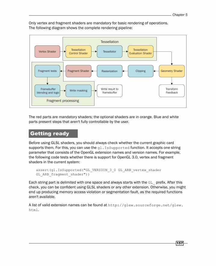
Only vertex and fragment shaders are mandatory for basic rendering of operations. The following diagram shows the complete rendering pipeline:
Tessellation
Fragment processing
Vertex ShaderTessellation
Control ShaderTessellator
Fragment tests Fragment Shader Rasterization Clipping Geometry Shader
TessellationEvaluation Shader
TransformFeedback
Write maskingFramebufferblending and logic
Write result toframebuffer
The red parts are mandatory shaders; the optional shaders are in orange. Blue and white parts present steps that aren't fully controllable by the user.
Getting readyBefore using GLSL shaders, you should always check whether the current graphic card supports them. For this, you can use the gl.IsSupported function. It accepts one string parameter that consists of the OpenGL extension names and version names. For example, the following code tests whether there is support for OpenGL 3.0, vertex and fragment shaders in the current system:
assert(gl.IsSupported("GL_VERSION_3_0 GL_ARB_vertex_shader GL_ARB_fragment_shader"))
Each string part is delimited with one space and always starts with the GL_ prefi x. After this check, you can be confi dent using GLSL shaders or any other extension. Otherwise, you might end up producing memory access violation or segmentation fault, as the required functions aren't available.
A list of valid extension names can be found at http://glew.sourceforge.net/glew.html.
Graphics – Modern Method with OpenGL 3.0+
158
You'll need the valid shader source code. You can use the following example of the vertex shader source code:
local shader_source = [[#version 330 //use GLSL specifi cation version 3.3layout (location = 0) in vec3 VertexPosition;layout (location = 1) in vec4 VertexColor;layout (location = 2) in vec2 VertexTexCoord;
out vec4 Color;out vec2 TexCoord;
void main(){ gl_Position = vec4(VertexPosition.xyz, 1.0); Color = vec4(VertexColor.rgba); TexCoord = vec2(VertexTexCoord.xy);}]]
This vertex shader uses GLSL version 3.3 and does basic preparation of vertex attributes for the next stage.
How to do it…GLSL shaders and programs use special OpenGL objects. These must be created before using. You can create the shader object with the gl.CreateShader function. It accepts the shader stage identifi er and results in a numerical object identifi er. Let's assume that this shader object identifi er is stored in the shader_object variable with the following code:
local shader_stage = gl_enum.GL_VERTEX_SHADERlocal shader_object = gl.CreateShader(shader_stage)
Now you can use this shader object to load your shader's source code:
gl.ShaderSource(shader_object, shader_source)
After this step, you can compile the shader with the gl.CompileShader function. You can check the shader compilation status with this code:
local compilation_status = ""local status = gl.GetShaderiv(shader_object, gl_enum.GL_COMPILE_STATUS)if status == gl_enum.GL_FALSE then compilation_status = gl.GetShaderInfoLog(shader_object)end
Chapter 5
159
The status variable contains a numerical value, which is set to GL_TRUE if the compilation is successful. Otherwise, it's set to GL_FALSE and you can obtain the textual error message with the gl.GetShaderInfoLog function.
After successful compilation, you can link shader objects into shader programs, but fi rst you must create one with the gl.CreateProgram function. It returns a numerical identifi er for the shader program. Let's store this value into the shader_program value as shown in the following code:
local shader_program = gl.CreateProgram()
Now you can attach the shader objects into the shader program with the following command:
gl.AttachShader(shader_program, shader_object)
With this step done, you can fi nally link shaders into the program with the command:
gl.LinkProgram(shader_program)
You should always check for the last linking operation status with the following code:
local link_status = ""local status = gl.GetProgramiv(shader_program, gl_enum.GL_LINK_STATUS)if status == gl_enum.GL_FALSE then link_status = gl.GetProgramInfoLog(shader_program)end
After the shader program is linked, the shader objects are not needed anymore and you can safely delete them with:
gl.DeleteShader(shader_object)
The shader program can be used with the following code:
gl.UseProgram(shader_program)
If there's no need for the shader program, you can delete it with the following code:
gl.DeleteProgram(shader_program)
Graphics – Modern Method with OpenGL 3.0+
160
How it works…The GLSL shader loading process consists of two steps. The fi rst step is the shader stage compilation into the shader object. It works in a similar fashion as in a C compiler, where the source code is compiled into binary object fi les. The compilation is followed by the linking process. Shader objects are linked into one shader program. This presents the fi nal result of the GLSL shader preparation process. Of course, your application might contain more than one shader program and you can switch between them. On some rare occasions, it's better to merge more shaders into one and separate them with conditional blocks. This approach introduces additional overhead to the shader code especially in fragment shader, but this might be better than switching shaders. There's no general rule for this, so you'll need to experiment.
When you're writing your own shaders, you should always take into account the amount of shader runs for each element. For instance, the vertex shader is used on every vertex, whereas the fragment shader is almost always used many more times as it operates on fragment elements. You can think of fragments as pixels on the frame buffer. So, whenever you're writing a program for the fragment shader, try to think about implementing it in the vertex shader fi rst. This way you can further optimize your shaders, especially if you intend to use them in an application on mobile devices.
See also The Using uniform variables with shaders recipe
The Writing a vertex shader recipe
The Writing a fragment (pixel) shader recipe
Using uniform variables with shadersUniform variables present a way to pass variables from the application into GLSL shaders. However, you are limited to pass numerical values, vectors, and matrices only.
The dynamic rendering pipeline doesn't use immediate mode functions to set up vertices or matrices. This means functions such as gl.Vertex, gl.Rotate, gl.Translate, and gl.Scale are of no use anymore. For this situation, vertices are stored in vertex buffers. Other variables such as model view and projection matrix have to be supplied by uniform variables. These variables are also used often to set up or change the behavior of the shader program during runtime. For example, you can adjust the glowing effect amount in your shader program.
Chapter 5
161
Getting readyEach uniform variable has its own numerical location identifi er. This identifi er is used to access almost any uniform variable. The location identifi er is limited to primitive values such as integer, fl oat, and vectors. Matrices present a special case where you can upload the whole matrix in one step, but you can retrieve only one element from the shader program at one time. You can obtain a uniform variable location with the gl.GetUniformLocation function. There are three ways to use this function:
The location of a single primitive value:
local location = gl.GetUniformLocation(shader_program, "variable_name")
The location of an array element:
local location = gl.GetUniformLocation(shader_program, "array_variable[1]")
The location of a structure element:
local location = gl.GetUniformLocation(shader_program, "structure_variable.element")
Let's assume that shader_program is the valid identifi er for the shader program. This function returns the location identifi er of the specifi ed uniform variable. If such a variable doesn't exist in the shader program or is discarded in the process of compilation, the returned value is -1. The uniform variable is discarded if it isn't actively used in the shader program.
How to do it…Now that you've got the location of the uniform variable, you can either set the content of the uniform variable or obtain its value.
Writing into uniform variablesYou can set the uniform variable by one of these three functions: gl.Uniformi, gl.Uniformf, and gl.UniformMatrix. The fi rst one is used in integer values, the second is for fl oat number, and the last one is for matrices.
Both gl.Uniformi and gl.Uniformf accept two to fi ve parameters. The fi rst one is always the location of the uniform variable. The second one can be a primitive numeric value or Lua table. Lua tables are usually used for vectors. The following examples show how to set a primitive fl oat number and a vector of fl oats:
local primitive_value = 1.5local vector = {1.0, 2.0, 3.0}gl.Uniformf(location, primitive_value)
Graphics – Modern Method with OpenGL 3.0+
162
gl.Uniformf(location, vector[1], vector[2], vector[3])gl.Uniformf(location, vector)
Setting up matrices is a bit more diffi cult. Matrix values have to be stored in a fl at Lua table. Matrix sizes can vary from 2 x 2 to 4 x 4 elements. You can also let the gl.UniformMatrix function to transpose your matrix. It means that matrix rows will be swapped with matrix columns. This is useful if you're supplying matrices that consist of multiple vectors. The following example shows how to upload the whole matrix of size 4 x 4:
local x,y,z = 1,2,3local translation = { 1, 0, 0, x, 0, 1, 0, y, 0, 0, 1, z, 0, 0, 0, 1,}local rows, columns = 4, 4local transpose = falsegl.UniformMatrix(location, translation, rows, columns, transpose)
Reading from uniform variablesUniform variables can be read from shader programs with the gl.GetUniform functions. There are four versions of this function. One for each type of value: integer, unsigned integer, fl oat, and double. Each of these functions can return one or more variables as return values. This depends on whether the queried variable is a primitive type such as a fl oat, an integer, or a vector. The following table lists all the versions of the gl.GetUniform function:
Function names Return typesgl.GetUniformi Integer
gl.GetUniformui Unsigned integer
gl.GetUniformf Float
gl.GetUniformd Double
Generic function specifi cation accepts two arguments:
gl.GetUniform(shader_program, location)
For example, if you'd want to obtain a 3D vector from the shader program, you'd use the following code:
local x,y,z = gl.GetUniformf(shader_program, location)
All three variables would be fi lled with vector variable content.
Chapter 5
163
How it works…Uniform variables are available for all parts of the shader program. For instance, you can access the same uniform variable from the vertex and fragment shaders. You should always try to minimize the amount of uniform variable updates. Every update consumes a small part of bandwidth between CPU memory and GPU memory.
Writing a vertex shaderVertex shaders are programs that operate on vertices and their attributes. This stage is also used to apply matrix transformations as well. GLSL shader programs use input and output variables. In the case of a vertex shader, input variables are either uniforms or vertex buffer data. Output variables are passed to the next stage of rendering the pipeline. There are also special built-in variables such as gl_Position, gl_PointSize, and others. These are mostly used with fi xed functionality and may not be redeclared.
All shaders use the entry point function—main. This function is applied on each element—vertex.
Getting readyThis recipe will use the GLSL shading language with version 3.3. It assumes that all the vertices are stored in Vertex Buffer Object (VBO). The vertex shader program is applied on every vertex that is contained within VBO.
To prepare the vertex shader, you'll need to create the shader object fi rst:
local shader_stage = gl_enum.GL_VERTEX_SHADERlocal shader_object = gl.CreateShader(shader_stage)
How to do it…The shader programs code can be stored in a text fi le or you can submit it directly as a string value. This recipe will use the latter method. The following source code will defi ne the basic vertex shader:
local shader_source = [[//Requires GLSL 3.3 at least#version 330
//Input variables – vertex attributeslayout (location = 0) in vec3 VertexPosition;layout (location = 1) in vec4 VertexColor;layout (location = 2) in vec2 VertexTexCoord;
Graphics – Modern Method with OpenGL 3.0+
164
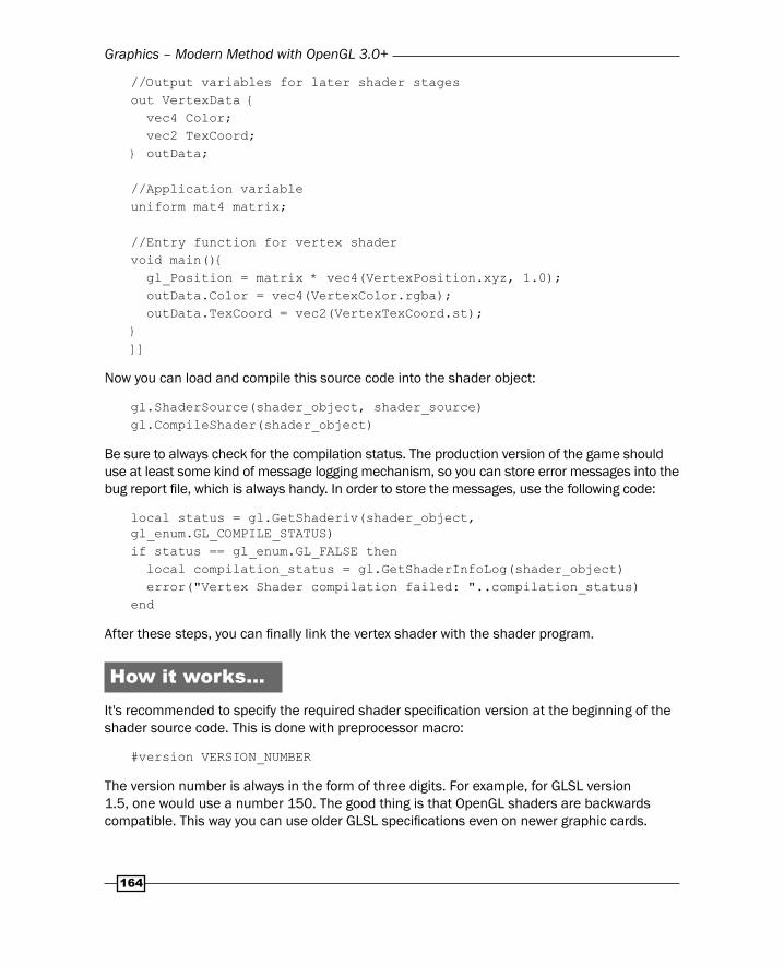
//Output variables for later shader stagesout VertexData { vec4 Color; vec2 TexCoord;} outData;
//Application variableuniform mat4 matrix;
//Entry function for vertex shadervoid main(){ gl_Position = matrix * vec4(VertexPosition.xyz, 1.0); outData.Color = vec4(VertexColor.rgba); outData.TexCoord = vec2(VertexTexCoord.st);}]]
Now you can load and compile this source code into the shader object:
gl.ShaderSource(shader_object, shader_source)gl.CompileShader(shader_object)
Be sure to always check for the compilation status. The production version of the game should use at least some kind of message logging mechanism, so you can store error messages into the bug report fi le, which is always handy. In order to store the messages, use the following code:
local status = gl.GetShaderiv(shader_object, gl_enum.GL_COMPILE_STATUS)if status == gl_enum.GL_FALSE then local compilation_status = gl.GetShaderInfoLog(shader_object) error("Vertex Shader compilation failed: "..compilation_status)end
After these steps, you can fi nally link the vertex shader with the shader program.
How it works…It's recommended to specify the required shader specifi cation version at the beginning of the shader source code. This is done with preprocessor macro:
#version VERSION_NUMBER
The version number is always in the form of three digits. For example, for GLSL version 1.5, one would use a number 150. The good thing is that OpenGL shaders are backwards compatible. This way you can use older GLSL specifi cations even on newer graphic cards.
Chapter 5
165
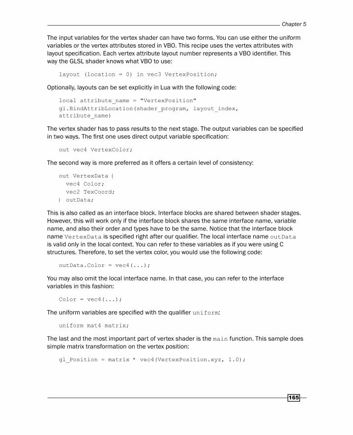
The input variables for the vertex shader can have two forms. You can use either the uniform variables or the vertex attributes stored in VBO. This recipe uses the vertex attributes with layout specifi cation. Each vertex attribute layout number represents a VBO identifi er. This way the GLSL shader knows what VBO to use:
layout (location = 0) in vec3 VertexPosition;
Optionally, layouts can be set explicitly in Lua with the following code:
local attribute_name = "VertexPosition"gl.BindAttribLocation(shader_program, layout_index, attribute_name)
The vertex shader has to pass results to the next stage. The output variables can be specifi ed in two ways. The fi rst one uses direct output variable specifi cation:
out vec4 VertexColor;
The second way is more preferred as it offers a certain level of consistency:
out VertexData { vec4 Color; vec2 TexCoord;} outData;
This is also called as an interface block. Interface blocks are shared between shader stages. However, this will work only if the interface block shares the same interface name, variable name, and also their order and types have to be the same. Notice that the interface block name VertexData is specifi ed right after our qualifi er. The local interface name outData is valid only in the local context. You can refer to these variables as if you were using C structures. Therefore, to set the vertex color, you would use the following code:
outData.Color = vec4(...);
You may also omit the local interface name. In that case, you can refer to the interface variables in this fashion:
Color = vec4(...);
The uniform variables are specifi ed with the qualifi er uniform:
uniform mat4 matrix;
The last and the most important part of vertex shader is the main function. This sample does simple matrix transformation on the vertex position:
gl_Position = matrix * vec4(VertexPosition.xyz, 1.0);
Graphics – Modern Method with OpenGL 3.0+
166
It takes three coordinates x, y, and z in the form of a vector with three elements. This vector is extended to contain four elements with the vec4 type declaration. Notice that the forth element is set to 1. This is because the matrix multiplication rule must be applied. The A x B matrix can be multiplied only with matrix B x C. This will result in A x C matrix. In this case, you are using 4 x 4 matrix and you multiply it with the 4 x 1 matrix. Vectors with N elements can be seen as matrices with the size of N x 1. The result of this is a 4 x 1 matrix or a vector with four elements.
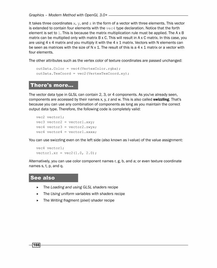
The other attributes such as the vertex color of texture coordinates are passed unchanged:
outData.Color = vec4(VertexColor.rgba);outData.TexCoord = vec2(VertexTexCoord.xy);
There's more…The vector data type in GLSL can contain 2, 3, or 4 components. As you've already seen, components are accessed by their names x, y, z and w. This is also called swizzling. That's because you can use any combination of components as long as you maintain the correct output data type. Therefore, the following code is completely valid:
vec2 vector1;vec3 vector2 = vector1.xxy;vec4 vector3 = vector2.zwyx;vec4 vector4 = vector1.xxxx;
You can use swizzling even on the left side (also known as l-value) of the value assignment:
vec4 vector1;vector1.xz = vec2(1.0, 2.0);
Alternatively, you can use color component names r, g, b, and a; or even texture coordinate names s, t, p, and q.
See also The Loading and using GLSL shaders recipe
The Using uniform variables with shaders recipe
The Writing fragment (pixel) shader recipe
Chapter 5
167
Writing a fragment (pixel) shaderFragment shader operates on pixel fragments from the rasterization process. The rasterizer transforms the whole graphical scene into a set of values that form fragments. A set of values that are related to one graphical primitive is called a fragment. These values may contain colors, alpha transparency, depth values, or even user supplied data. The fragment shader program might even decide whether to discard certain pixels from being drawn into the frame buffer.
Fragment shaders are often used in two-pass postprocessing. In the fi rst pass, the whole scene is rendered into the texture or a buffer by using the fi rst fragment shader. This shader renders primitives without postprocessing effects. In the second pass, this texture is used on a rectangle that covers the whole screen. This pass uses the fragment shader to control rendering of the texture on the rectangle. This way you can apply various effects such as High Defi nition Range transformation—HDR, screen distortions, and many others.
The other uses of the fragment shader may be per pixel lighting and shadows.
Keep in mind that fragment shaders usually use more iterations than vertex shaders. Therefore, always try to minimize the complexity of the fragment shader program.
Getting readyThe preparation of the fragment shader is fairly similar to the preparation of the vertex shader:
local shader_stage = gl_enum.GL_FRAGMENT_SHADERlocal shader_object = gl.CreateShader(shader_stage)
This will create the shader object, which you can use to load and compile the shader source code.
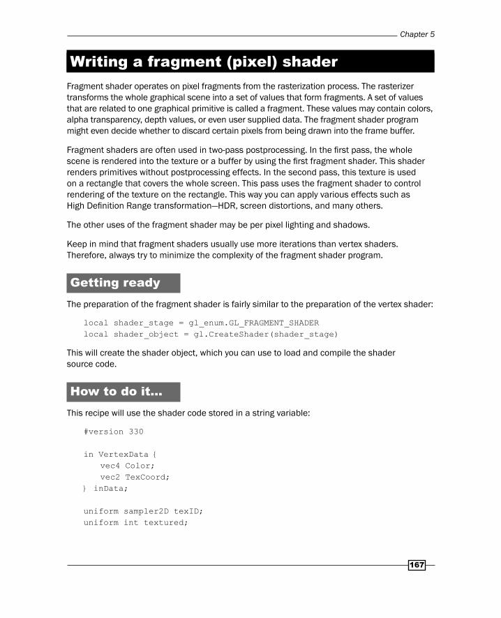
How to do it…This recipe will use the shader code stored in a string variable:
#version 330
in VertexData { vec4 Color; vec2 TexCoord;} inData;
uniform sampler2D texID;uniform int textured;
Graphics – Modern Method with OpenGL 3.0+
168
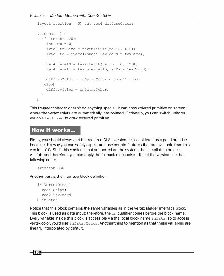
layout(location = 0) out vec4 diffuseColor;
void main() { if (textured>0){ int LOD = 0; ivec2 texSize = textureSize(texID, LOD); ivec2 tc = ivec2(inData.TexCoord * texSize);
vec4 texel0 = texelFetch(texID, tc, LOD); vec4 texel1 = texture(texID, inData.TexCoord);
diffuseColor = inData.Color * texel1.rgba; }else{ diffuseColor = inData.Color; }}
This fragment shader doesn't do anything special. It can draw colored primitive on screen where the vertex colors are automatically interpolated. Optionally, you can switch uniform variable textured to draw textured primitive.
How it works…Firstly, you should always set the required GLSL version. It's considered as a good practice because this way you can safely expect and use certain features that are available from this version of GLSL. If this version is not supported on the system, the compilation process will fail, and therefore, you can apply the fallback mechanism. To set the version use the following code:
#version 330
Another part is the interface block defi nition:
in VertexData { vec4 Color; vec2 TexCoord;} inData;
Notice that this block contains the same variables as in the vertex shader interface block. This block is used as data input; therefore, the in qualifi er comes before the block name. Every variable inside this block is accessible via the local block name inData, so to access vertex color, you'd use inData.Color. Another thing to mention as that these variables are linearly interpolated by default.
Chapter 5
169
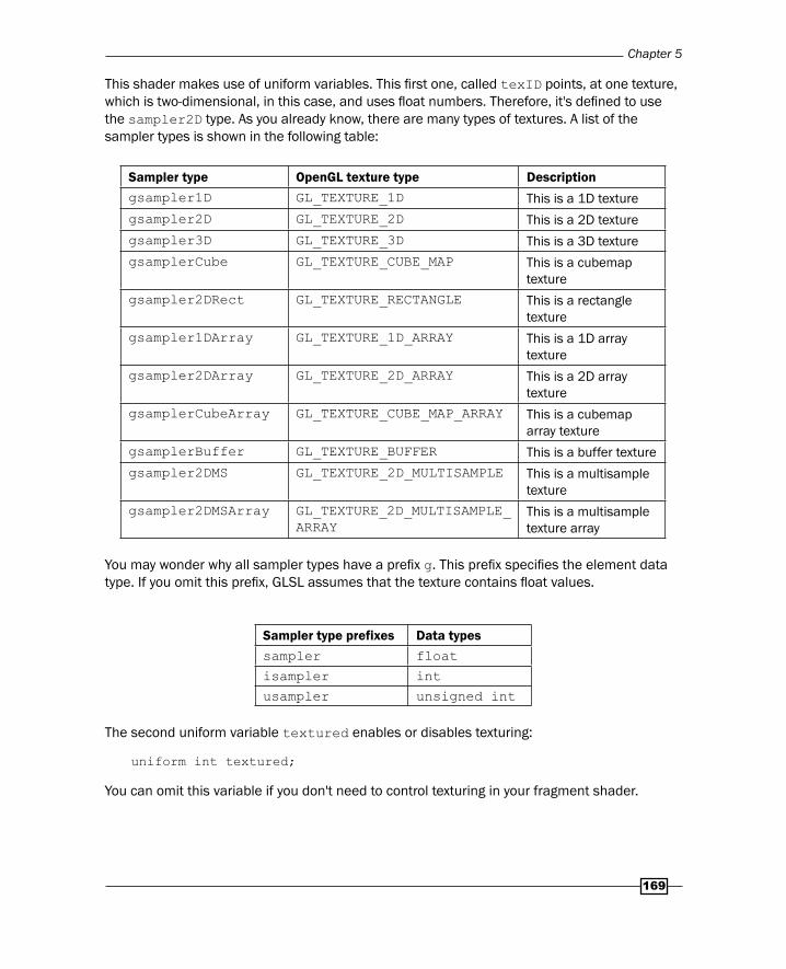
This shader makes use of uniform variables. This fi rst one, called texID points, at one texture, which is two-dimensional, in this case, and uses fl oat numbers. Therefore, it's defi ned to use the sampler2D type. As you already know, there are many types of textures. A list of the sampler types is shown in the following table:
Sampler type OpenGL texture type Descriptiongsampler1D GL_TEXTURE_1D This is a 1D texture
gsampler2D GL_TEXTURE_2D This is a 2D texture
gsampler3D GL_TEXTURE_3D This is a 3D texture
gsamplerCube GL_TEXTURE_CUBE_MAP This is a cubemap texture
gsampler2DRect GL_TEXTURE_RECTANGLE This is a rectangle texture
gsampler1DArray GL_TEXTURE_1D_ARRAY This is a 1D array texture
gsampler2DArray GL_TEXTURE_2D_ARRAY This is a 2D array texture
gsamplerCubeArray GL_TEXTURE_CUBE_MAP_ARRAY This is a cubemap array texture
gsamplerBuffer GL_TEXTURE_BUFFER This is a buffer texture
gsampler2DMS GL_TEXTURE_2D_MULTISAMPLE This is a multisample texture
gsampler2DMSArray GL_TEXTURE_2D_MULTISAMPLE_ARRAY
This is a multisample texture array
You may wonder why all sampler types have a prefi x g. This prefi x specifi es the element data type. If you omit this prefi x, GLSL assumes that the texture contains fl oat values.
Sampler type prefixes Data typessampler float
isampler int
usampler unsigned int
The second uniform variable textured enables or disables texturing:
uniform int textured;
You can omit this variable if you don't need to control texturing in your fragment shader.
Graphics – Modern Method with OpenGL 3.0+
170
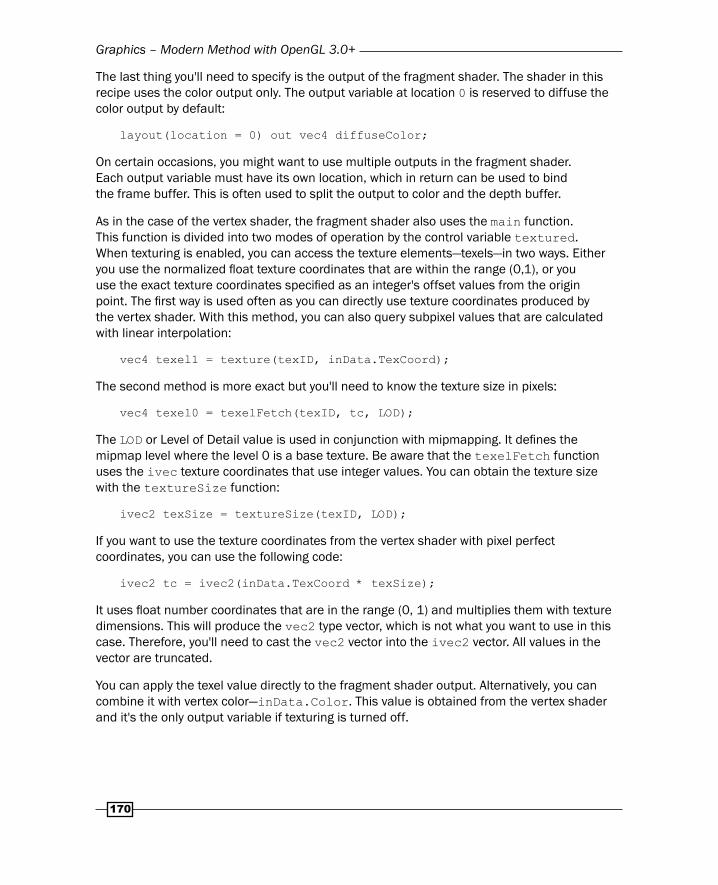
The last thing you'll need to specify is the output of the fragment shader. The shader in this recipe uses the color output only. The output variable at location 0 is reserved to diffuse the color output by default:
layout(location = 0) out vec4 diffuseColor;
On certain occasions, you might want to use multiple outputs in the fragment shader. Each output variable must have its own location, which in return can be used to bind the frame buffer. This is often used to split the output to color and the depth buffer.
As in the case of the vertex shader, the fragment shader also uses the main function. This function is divided into two modes of operation by the control variable textured. When texturing is enabled, you can access the texture elements—texels—in two ways. Either you use the normalized fl oat texture coordinates that are within the range (0,1), or you use the exact texture coordinates specifi ed as an integer's offset values from the origin point. The fi rst way is used often as you can directly use texture coordinates produced by the vertex shader. With this method, you can also query subpixel values that are calculated with linear interpolation:
vec4 texel1 = texture(texID, inData.TexCoord);
The second method is more exact but you'll need to know the texture size in pixels:
vec4 texel0 = texelFetch(texID, tc, LOD);
The LOD or Level of Detail value is used in conjunction with mipmapping. It defi nes the mipmap level where the level 0 is a base texture. Be aware that the texelFetch function uses the ivec texture coordinates that use integer values. You can obtain the texture size with the textureSize function:
ivec2 texSize = textureSize(texID, LOD);
If you want to use the texture coordinates from the vertex shader with pixel perfect coordinates, you can use the following code:
ivec2 tc = ivec2(inData.TexCoord * texSize);
It uses fl oat number coordinates that are in the range (0, 1) and multiplies them with texture dimensions. This will produce the vec2 type vector, which is not what you want to use in this case. Therefore, you'll need to cast the vec2 vector into the ivec2 vector. All values in the vector are truncated.
You can apply the texel value directly to the fragment shader output. Alternatively, you can combine it with vertex color—inData.Color. This value is obtained from the vertex shader and it's the only output variable if texturing is turned off.
Chapter 5
171
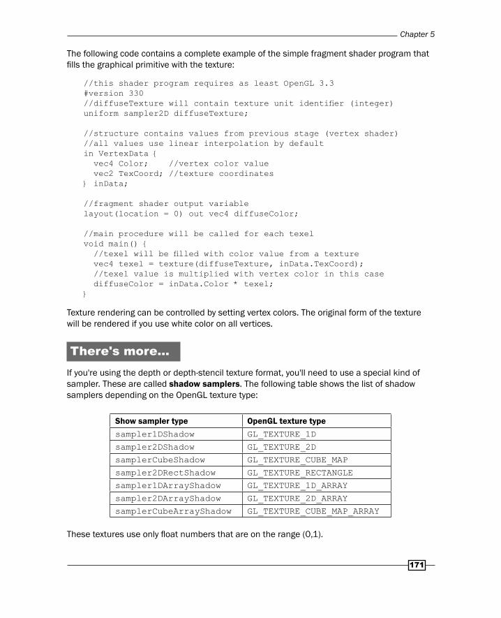
The following code contains a complete example of the simple fragment shader program that fi lls the graphical primitive with the texture:
//this shader program requires as least OpenGL 3.3#version 330//diffuseTexture will contain texture unit identifi er (integer)uniform sampler2D diffuseTexture;
//structure contains values from previous stage (vertex shader)//all values use linear interpolation by defaultin VertexData { vec4 Color; //vertex color value vec2 TexCoord; //texture coordinates} inData;
//fragment shader output variablelayout(location = 0) out vec4 diffuseColor;
//main procedure will be called for each texelvoid main() { //texel will be fi lled with color value from a texture vec4 texel = texture(diffuseTexture, inData.TexCoord); //texel value is multiplied with vertex color in this case diffuseColor = inData.Color * texel;}
Texture rendering can be controlled by setting vertex colors. The original form of the texture will be rendered if you use white color on all vertices.
There's more…If you're using the depth or depth-stencil texture format, you'll need to use a special kind of sampler. These are called shadow samplers. The following table shows the list of shadow samplers depending on the OpenGL texture type:
Show sampler type OpenGL texture typesampler1DShadow GL_TEXTURE_1D
sampler2DShadow GL_TEXTURE_2D
samplerCubeShadow GL_TEXTURE_CUBE_MAP
sampler2DRectShadow GL_TEXTURE_RECTANGLE
sampler1DArrayShadow GL_TEXTURE_1D_ARRAY
sampler2DArrayShadow GL_TEXTURE_2D_ARRAY
samplerCubeArrayShadow GL_TEXTURE_CUBE_MAP_ARRAY
These textures use only fl oat numbers that are on the range (0,1).
Graphics – Modern Method with OpenGL 3.0+
172
See also The Using uniform variables with shaders recipe
The Writing vertex shader recipe
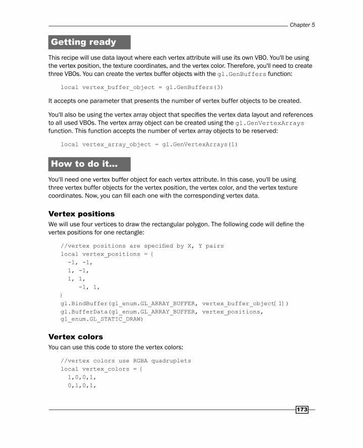
Drawing primitives using vertex buffersVBO was, in the past, a part of an OpenGL as an extension. With the new OpenGL specifi cation, the VBO mechanism is included in the GLSL specifi cation. This means that you can reuse much of the existing functionality with small changes. VBOs present an opaque storage for data; therefore, they might contain the vertex positions, texture coordinates, colors or any other data. GLSL shaders can use these buffers but they must be differentiated so the shader program knows what data is stored inside of these buffers. That's where the vertex array objects or VAO come in. The vertex array object is a structure that merges VBOs for use in the shader program. They are used in GLSL shader programs as a main source of vertex attributes. Each of the attributes can be submitted in its own VBO. It ensures effi cient upload of all vertices into graphic memory and you can easily add other vertices if needed.
You may fi nd it desirable to use interleaved data format for VBO. It's a way to store all the vertex attributes into one vertex buffer. Examples of data layout are shown in the following diagram:
VBO VBOVBO
VBO
VBO
V
V
V V V
V
V
V
V
N
N
N
N
N
N
N
N
N
C
C
C
C
C
C
C
C
C
There are three cases of decisions on data layout:
Each vertex attribute has its own VBO—vertices, normal vectors, and vertex colors.
All the attributes are stored in one VBO. They are grouped by the attribute type.
All the attributes are stored in one VBO. They are grouped by the vertex.
Note that if you plan on frequent updating of vertex attributes, it's better to reserve the whole VBO for this purpose. This way OpenGL can optimize memory access to vertex attributes.
Chapter 5
173
Getting readyThis recipe will use data layout where each vertex attribute will use its own VBO. You'll be using the vertex position, the texture coordinates, and the vertex color. Therefore, you'll need to create three VBOs. You can create the vertex buffer objects with the gl.GenBuffers function:
local vertex_buffer_object = gl.GenBuffers(3)
It accepts one parameter that presents the number of vertex buffer objects to be created.
You'll also be using the vertex array object that specifi es the vertex data layout and references to all used VBOs. The vertex array object can be created using the gl.GenVertexArrays function. This function accepts the number of vertex array objects to be reserved:
local vertex_array_object = gl.GenVertexArrays(1)
How to do it…You'll need one vertex buffer object for each vertex attribute. In this case, you'll be using three vertex buffer objects for the vertex position, the vertex color, and the vertex texture coordinates. Now, you can fi ll each one with the corresponding vertex data.
Vertex positionsWe will use four vertices to draw the rectangular polygon. The following code will defi ne the vertex positions for one rectangle:
//vertex positions are specifi ed by X, Y pairslocal vertex_positions = { -1, -1, 1, -1, 1, 1, -1, 1,}gl.BindBuffer(gl_enum.GL_ARRAY_BUFFER, vertex_buffer_object[1])gl.BufferData(gl_enum.GL_ARRAY_BUFFER, vertex_positions, gl_enum.GL_STATIC_DRAW)
Vertex colorsYou can use this code to store the vertex colors:
//vertex colors use RGBA quadrupletslocal vertex_colors = { 1,0,0,1, 0,1,0,1,
Graphics – Modern Method with OpenGL 3.0+
174
0,0,1,1, 1,1,0,1,}gl.BindBuffer(gl_enum.GL_ARRAY_BUFFER, vertex_buffer_object[2])gl.BufferData(gl_enum.GL_ARRAY_BUFFER, vertex_colors, gl_enum.GL_STATIC_DRAW)
Vertex texture coordinatesThe following code will defi ne the texture coordinates for vertices:
//texture coordinates use U, V coordinate pairslocal vertex_texcoords = { 0, 0, 1, 0, 1, 1, 0, 1,}gl.BindBuffer(gl_enum.GL_ARRAY_BUFFER, vertex_buffer_object[3])gl.BufferData(gl_enum.GL_ARRAY_BUFFER, vertex_texcoords, gl_enum.GL_STATIC_DRAW)
Now that you have data stored in VBOs, you'll have to bind them into VAO. The vertex array object contains data layout information. For instance, if the vertex position consists of three dimensions, each vertex will use three subsequent values from VBO that contains vertex positions.
Before using the vertex array object, you'll need to bind it with the gl.BindVertexArray function:
gl.BindVertexArray(vertex_array_object[1])
Another step is enabling and mapping vertex attributes to buffers. In this recipe, each vertex contains three vertex attributes: the vertex position, the vertex color and the texture coordinate. Each vertex attribute will use different attribute index. This index will correspond to the location value in the shader source:
layout (location = 0) in vec3 VertexPosition;
The vertex attribute is mapped by a pair of functions: gl.BindBuffer and gl.VertexAttribPointer. The fi rst one prepares VBO to be used. The second command uses this function specifi cation:
gl.VertexAttribPointer(location_index, vertex_elements_count, normalized, stride)
Chapter 5
175
The fi nal code will look like this:
-- vertex positiongl.BindBuffer(gl_enum.GL_ARRAY_BUFFER, vertex_buffer_object[1])gl.VertexAttribPointer(0, 2, false, 0)
-- vertex colorgl.BindBuffer(gl_enum.GL_ARRAY_BUFFER, vertex_buffer_object[2])gl.VertexAttribPointer(1, 4, false, 0)
-- texture coordinatesgl.BindBuffer(gl_enum.GL_ARRAY_BUFFER, vertex_buffer_object[3])gl.VertexAttribPointer(2, 2, false, 0)
Notice that the vertex position is specifi ed by two elements (x, y), vertex color by four elements (r, g, b, a) and texture coordinates by two elements (s, t).
The last thing you'll need to do before drawing is enabling vertex attributes with the gl.EnableVertexAttribArray function.
gl.EnableVertexAttribArray(0)gl.EnableVertexAttribArray(1)gl.EnableVertexAttribArray(2)
Alternatively, you can disable certain vertex attributes with the gl.DisableVertexArray function:
gl.DisableVertexAttribArray(attribute_index)
After all these steps, you are ready to use VBOs and VAO to effi ciently draw vertices. Don't forget to bind the currently used vertex array object before drawing. Otherwise, OpenGL wouldn't know what data to use and you could get unpredictable results.
Vertices can be drawn by using the gl.DrawArrays function:
gl.DrawArrays(gl_enum.GL_QUADS, 0, 4)
The fi rst parameter specifi es what graphic primitive will be used. It uses the same constants as were used in the gl.Begin function. The second parameter sets the vertex offset and the last one is a number of vertices to be used.
Graphics – Modern Method with OpenGL 3.0+
176
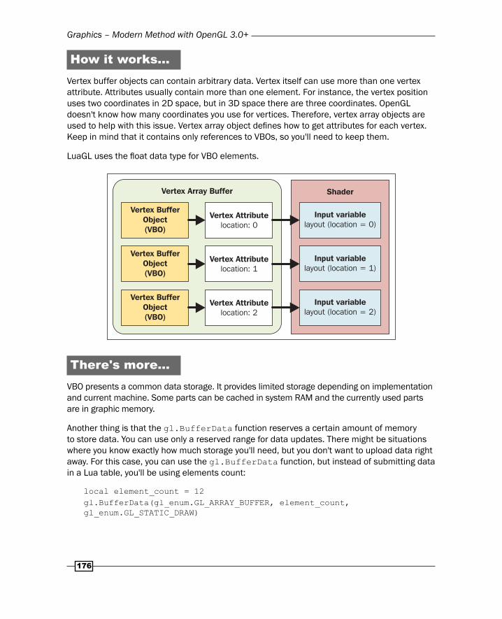
How it works…Vertex buffer objects can contain arbitrary data. Vertex itself can use more than one vertex attribute. Attributes usually contain more than one element. For instance, the vertex position uses two coordinates in 2D space, but in 3D space there are three coordinates. OpenGL doesn't know how many coordinates you use for vertices. Therefore, vertex array objects are used to help with this issue. Vertex array object defi nes how to get attributes for each vertex. Keep in mind that it contains only references to VBOs, so you'll need to keep them.
LuaGL uses the fl oat data type for VBO elements.
Vertex Array Buffer Shader
Vertex BufferObject(VBO)
Vertex BufferObject(VBO)
Vertex BufferObject(VBO)
Vertex Attributelocation: 0
Vertex Attributelocation: 1
Vertex Attributelocation: 2
Input variablelayout (location = 0)
Input variablelayout (location = 1)
Input variablelayout (location = 2)
There's more…VBO presents a common data storage. It provides limited storage depending on implementation and current machine. Some parts can be cached in system RAM and the currently used parts are in graphic memory.
Another thing is that the gl.BufferData function reserves a certain amount of memory to store data. You can use only a reserved range for data updates. There might be situations where you know exactly how much storage you'll need, but you don't want to upload data right away. For this case, you can use the gl.BufferData function, but instead of submitting data in a Lua table, you'll be using elements count:
local element_count = 12gl.BufferData(gl_enum.GL_ARRAY_BUFFER, element_count, gl_enum.GL_STATIC_DRAW)
Chapter 5
177
This will reserve memory space for 12 elements, which you can update with the gl.BufferSubData function:
local offset = 0local data = {1,2,3,4}gl.BufferSubData(gl_enum.GL_ARRAY_BUFFER, offset, data)
The offset parameter presents a number of elements to be skipped.
See also The Using uniform variables with shaders recipe
The Writing a vertex shader recipe
The Writing a fragment (pixel) shader recipe
Rendering to textureRendering to texture technique is used whenever you need to apply some kind of postprocessing on screen or to produce dynamic textures in refl ections.
Over the past few years, OpenGL introduced a number of ways to obtain screen content and transfer it to texture. You could read directly from the frame buffer and store all data in texture with gl.TexSubImage2D function. This approach is a slow process because all rendering must be stalled in order to obtain a copy of the whole frame. For this kind of operation, there was a P buffer introduced sometime in 2000. It presented a more effi cient way of transferring larger blocks of pixel data. However, this kind of buffer wasn't available everywhere and what's more, it was hard to use. Later, it was deprecated in OpenGL 3.0 and subsequently removed from OpenGL 3.1. Currently, the standardized way of working with frame buffer is to work with Render Buffer. Render buffer objects have been available since OpenGL 3.0. They use native pixel format, which makes them optimized for offscreen rendering target. The older technique used a texture as a target and used the pixel format conversion in each update which is slow.
This recipe will show you how to prepare and use render buffer object.
Getting readyYou can attach render buffers to various kinds of data that frame buffer produces. Render buffer can store color data, depth information, or stencil data.
Each render buffer will need to know its dimensions. Let's assume that you have this information already since you need to have the application window in order to display anything. The size of the application window will be stored in these variables: screen_width and screen_height.
Graphics – Modern Method with OpenGL 3.0+
178
You'll also need a valid texture that will be used as a rendering target. This texture will contain screen content and it will use the texture identifi er stored in the screen_texture variable. Note that this texture should be at least as big as the application window.
How to do it…First, you'll need to create the frame buffer object or FBO:
local fbos = gl.GenFrameBuffers(1)
The next thing is to activate this frame buffer:
gl.BindFramebuffer(gl_enum.GL_FRAMEBUFFER, fbos[1])
With this set, you can proceed to individual render buffers. This recipe will show you how to create and use the render buffer for color data and depth information.
The render buffer with the color attachmentThe render buffer with the color attachment is used often for offscreen rendering in order to do postprocessing effects. Render buffer will use all four color components, where each one will use 8 bits. This means that one color value will use 32 bits or 4 bytes:
local render_buffers = gl.GenRenderBuffers(1)local internal_format = gl_enum.GL_RGBA8local rb_target = gl_enum.GL_RENDERBUFFERlocal fb_target = gl_enum.GL_FRAMEBUFFERlocal attachment = gl_enum.GL_COLOR_ATTACHMENT0
gl.BindRenderBuffer(rb_target, render_buffers[1])gl.RenderBufferStorage(rb_target, internal_format, screen_width, screen_height)gl.FramebufferRenderbuffer(fb_target, attachment, rb_target, render_buffers[1])
The render buffer with the depth attachmentThe render buffer with the depth data usage can be seen in deferred shading or depth of fi eld effects. Deferred shading is a process where the graphical scene is rendered into separate parts—buffers. These buffers usually contain color information, map of normal vectors, and z depth. Basically, it skips all pixels that doesn't get to the screen (pixels that fail the Z test). This technique is used to save time spent by the fragment shader and it's used on complex scenes with a large number of lights:
local render_buffers = gl.GenRenderBuffers(1)local internal_format = gl_enum.GL_DEPTH_COMPONENT16local rb_target = gl_enum.GL_RENDERBUFFER
Chapter 5
179
local fb_target = gl_enum.GL_FRAMEBUFFERlocal attachment = gl_enum.GL_DEPTH_ATTACHMENT
gl.BindRenderBuffer(rb_target, render_buffers[1])gl.RenderBufferStorage(rb_target, internal_format, screen_width, screen_height)gl.FramebufferRenderbuffer(fb_target, attachment, rb_target, render_buffers[1])
You should always check the frame buffer has been prepared properly:
local status = gl.CheckFramebufferStatus(gl_enum.GL_DRAW_FRAMEBUFFER)if status ~= gl_enum.GL_FRAMEBUFFER_COMPLETE then error('Frame buffer is not complete!')end
After this step, you can switch rendering to this frame buffer with the gl.BindFramebuffer function:
gl.BindFramebuffer(gl_enum.GL_FRAMEBUFFER, fbos[1])
Alternatively, you can turn off rendering to this frame buffer with the following code:
gl.BindFramebuffer(gl_enum.GL_FRAMEBUFFER, 0)
This will cause rendering to the default frame buffer—screen.
OpenGL offers a very powerful function, gl.CopyImageSubData. It allows you to copy data from one buffer to another. This can be used to copy render buffer content to texture:
local src_level = 0local src_x, src_y, src_z = 0, 0, 0local dest_level = 0local dest_x, dest_y, dest_z = 0, 0, 0local src_width, src_height = screen_width, screen_heightlocal src_depth = 1
gl.CopyImageSubData( render_buffers[1], gl_enum.GL_RENDERBUFFER, src_level, src_x, src_y, src_z, screen_texture, gl_enum.GL_TEXTURE_2D, dest_level, dest_x, dest_y, dest_z, src_width, src_height, src_depth)
Graphics – Modern Method with OpenGL 3.0+
180
After this step, you can apply the screen_texture texture on polygons. Postprocessing is usually done by rendering this texture on one rectangular polygon that occupies the whole screen. This is shown in the following pseudo-code:
gl.BindFramebuffer(gl_enum.GL_FRAMEBUFFER, fbos[1]) draw_scene()gl.BindFramebuffer(gl_enum.GL_FRAMEBUFFER, 0)
gl.CopyImageSubData(...)draw_textured_quad_on_whole_screen()
How it works…OpenGL, by default, uses its own frame buffer. Frame buffer represents an abstract structure that sets the output for color data, depth information, and others. On the other hand, render buffer contains real data that has to be allocated in memory.
Render buffer uses native data format. Therefore, its content can be directly drawn on screen. Optionally, the render buffer content can be copied into the texture, which uses data format conversion. This approach is faster than rendering into texture fi rst with each frame.
See also The Writing a fragment (pixel) shader recipe
The Drawing primitives using vertex buffers recipe
Applying highlights and shadows to the scene
This recipe will deal with per-pixel lighting and simple shadowing. It will allow you to apply one or more lights in the 3D scene. There are two types of light sources: directional and positional light. Directional light doesn't have a position and it's used mostly for daylight. Positional light has a source at a certain position. This type of light can be divided to omnidirectional and spotlight. Omnidirectional light is used mostly with light bulbs. Spotlight is often used with refl ectors. Light intensity decreases with increasing distance from the light source.
This recipe will use simple shadowing. This means that surfaces that aren't directly facing the light source will be in the shadow. However, this doesn't include real shadow casting as this is a more advanced topic that's beyond the scope of this book.
Chapter 5
181
Getting readyBefore staring, you'll need to set up the camera position, object state in a scene, light sources, and materials. The camera position is stored in a structure, cameraState. It includes three matrices: position, rotation, and perspective correction. You could've multiplied these matrices into one but keep in mind that not every matrix is updated frame by frame. What's more, GPU can do matrix multiplication much faster than on CPU.
The object state is defi ned by object position. The position is computed from translation and rotation matrices stored in the positionState structure.
Light sources use a structure, lightState, that stores all the needed information about the light source such as light position, direction, attenuation, and spotlight parameters. The scene uses ambient light color, sceneAmbient, to emulate global illumination.
The last thing you'll need to set up is material parameters stored in the materialState structure.
You'll be setting uniform variables quite a lot. This means you'll be getting a uniform variable location on every access. To make uniform variable manipulation easier, you can bundle these operations into one function that stores location identifi ers in a table:
local uniformLocations = {}local uniformTypeFn = { f = gl.Uniformf, -- fl oat number d = gl.Uniformd, -- double fl oat number i = gl.Uniformi, -- integer number ui = gl.Uniformui, -- unsigned integer number m = gl.UniformMatrix, -- matrix}
local function setUniform(var_type, name, ...) -- uniform variable location is cached to speed up process local location = uniformLocations[name] if not location then location = gl.GetUniformLocation(shader_program, name) uniformLocations[name] = location end local uniformFn = uniformTypeFn[var_type] if type(uniformFn) == "function" then uniformFn(location, ...) endend
Graphics – Modern Method with OpenGL 3.0+
182
Do note that this function works on single shader programs. Each shader program must use its own uniformLocation table.
The last thing you'll need is a way to compute projection matrix for camera perspective correction. You can use the following example of a function to get the projection matrix based on the fi eld of a view angle, the screen aspect ratio, and the depth parameters. The projectionMatrix function is based on the computeFrustum function from the Setting up orthogonal and perspective camera recipe in Chapter 4, Graphics – Legacy Method with OpenGL 1.x-2.1. The main difference is that, in this case, it results in a transformation matrix. You can fi nd the whole derivation process of the projection matrix at http://www.songho.ca/opengl/gl_projectionmatrix.html.
The previous version relied on OpenGL to compute the matrix internally:
local function projectionMatrix(fov, aspect, znear, zfar) -- xymax variable refers to the coordinate -- of the right/bottom clip-plane local xymax = znear * math.tan(math.rad(fov/2)) local ymin = -xymax -- top clip-plane local xmin = -xymax -- left clip-plane
local width = xymax - xmin local height = xymax - ymin local depth = zfar - znear
-- q and qn parameters are used to achieve -- perspective correction local q = -(zfar + znear) / depth local qn = -2 * (zfar * znear) / depth
local w = 2 * znear / width w = w / aspect local h = 2 * znear / height
-- transposed version of the projection matrix return { w, 0, 0, 0, 0, h, 0, 0, 0, 0, q, -1, 0, 0, qn, 0, }end
Chapter 5
183
How to do it…The fi rst step is to supply the initial values to all uniform variables. This recipe will use one positional light source that is placed just next to the camera. The scene object is positioned in front of the camera:
-- camera parameterssetUniform('m', 'camera.translation', { 1,0,0,0, 0,1,0,0, 0,0,1,0, 0,0,0,1,}, 4, 4, true)setUniform('m', 'camera.rotation', { 1,0,0,0, 0,1,0,0, 0,0,1,0, 0,0,0,1,}, 4, 4, true)setUniform('m', 'camera.perspective', projectionMatrix(60, 1, 1, 10), 4, 4, true)
-- object parameterssetUniform('m', 'object.translation', { 1,0,0,-0.5, 0,1,0,-0.5, 0,0,1,-0.5, 0,0,0,1,}, 4, 4, true)setUniform('m', 'object.rotation', { 1,0,0,0, 0,1,0,0, 0,0,1,0, 0,0,0,1,}, 4, 4, true)
-- light parameterssetUniform('f', 'lights[0].position', {-1, 0, -1, 1})setUniform('f', 'lights[0].diffuse', {1, 0.8, 0.8, 1})setUniform('f', 'lights[0].specular', {1, 1, 1, 1})setUniform('f', 'lights[0].spotCutoff', 180.0)setUniform('f', 'lights[0].spotExponent', 1.2)setUniform('f', 'lights[0].constantAttenuation', 0)
Graphics – Modern Method with OpenGL 3.0+
184
setUniform('f', 'lights[0].linearAttenuation', 1)setUniform('f', 'lights[0].quadraticAttenuation', 0)setUniform('f', 'lights[0].spotDirection', {0, 0, 0})
setUniform('i', 'totalLights', 1)
-- material parameterssetUniform('f', 'material.ambient', {0.2, 0.2, 0.2, 1})setUniform('f', 'material.diffuse', {1, 1, 1, 1})setUniform('f', 'material.specular', {1, 1, 1, 1})setUniform('f', 'material.shininess', 5.0)
-- scene ambient colorsetUniform('f', 'sceneAmbient', {0.2, 0.2, 0.2, 1})
-- texturessetUniform('i', 'diffuseTexture', 0)
The next important thing is having correct vertex attributes. You'll need the vertex position, the vertex texture coordinates, and the vertex normal vector. Therefore, you'll need three vertex buffer objects. Each one for every vertex attribute:
local positionVBO = gl.GenBuffers(1)local texcoordVBO = gl.GenBuffers(1)local normalVBO = gl.GenBuffers(1)local vertex_array_object = gl.GenVertexArrays(1)
-- vertex coordinatesgl.BindBuffer(gl_enum.GL_ARRAY_BUFFER, positionVBO)gl.BufferData(gl_enum.GL_ARRAY_BUFFER, vertexPositions, gl_enum.GL_STATIC_DRAW)-- normal vector coordinatesgl.BindBuffer(gl_enum.GL_ARRAY_BUFFER-- texture coordinatesgl.BindBuffer(gl_enum.GL_ARRAY_BUFFER, texcoordVBO)gl.BufferData(gl_enum.GL_ARRAY_BUFFER, texcoords, gl_enum.GL_STATIC_DRAW), normalVBO)gl.BufferData(gl_enum.GL_ARRAY_BUFFER, normals, gl_enum.GL_STATIC_DRAW)
-- setup vertex attributesgl.BindVertexArray(vertex_array_object[1])
-- vertex position
Chapter 5
185
gl.BindBuffer(gl_enum.GL_ARRAY_BUFFER, positionVBO)gl.VertexAttribPointer(0, 3, false, 0)
-- vertex texture coordinatesgl.BindBuffer(gl_enum.GL_ARRAY_BUFFER, texcoordVBO)gl.VertexAttribPointer(1, 2, false, 0)
-- vertex normal vectorgl.BindBuffer(gl_enum.GL_ARRAY_BUFFER, normalVBO)gl.VertexAttribPointer(2, 3, false, 0)
Vertex shaderThe vertex shader code would look like this:
#version 330
struct cameraState{ mat4 perspective; mat4 translation; mat4 rotation;};
struct positionState{ mat4 translation; mat4 rotation;};
layout (location = 0) in vec3 VertexPosition;layout (location = 1) in vec2 VertexTexCoord;layout (location = 2) in vec3 VertexNormal;
out VertexData { vec2 texCoord; vec3 normal; vec3 position;} outData;
uniform fl oat time;uniform cameraState camera;uniform positionState object;
void main(){ // model-view matrix mat4 objMatrix = (object.translation * object.rotation);
Graphics – Modern Method with OpenGL 3.0+
186
// vertex position in the world vec4 localPos = objMatrix * vec4(VertexPosition.xyz, 1.0); // fi nal vertex position on screen gl_Position = (camera.perspective * camera.translation * camera.rotation) * localPos; // texture coordinates and original vertex position // for the next stage - fragment shader outData.texCoord = vec2(VertexTexCoord.st); outData.position = vertexPos.xyz; // normal vectors are adjusted to match object orientation vec4 tmpNormal = objMatrix * vec4(VertexNormal.xyz, 0.0); outData.normal = normalize(tmpNormal.xyz);}
Fragment shaderThe fragment shader code would contain these defi nitions:
#version 330// a structure for light parametersstruct lightState { vec4 position; vec4 diffuse; vec4 specular; fl oat constantAttenuation, linearAttenuation, quadraticAttenuation; fl oat spotCutoff, spotExponent; vec3 spotDirection;};// structure with material propertiesstruct materialState { vec4 ambient; vec4 diffuse; vec4 specular; fl oat shininess;};// camera position and orientation matricesstruct cameraState{ mat4 perspective; mat4 translation; mat4 rotation;};
// diffuseTexture contains texture unit identifi er (integer)uniform sampler2D diffuseTexture;
Chapter 5
187
uniform cameraState camera;uniform materialState material;// ambient light coloruniform vec4 sceneAmbient;
//total number of lights, currently 8 is the maximumuniform int totalLights; uniform lightState lights[8];
in VertexData { vec2 texCoord; vec3 normal; vec3 position;} inData;
layout(location = 0) out vec4 diffuseColor;
The whole light refl ection algorithm is packed into one function, processLighting. It accepts three parameters: material parameters, the current point on surface, and the normal vector. This makes the entire code much easier to read. Note that the processLighting function operates on voxels—points in space:
/* Input: material - material type specifi cation surface - voxel position in world space normalDirection - normal vector for current voxel*/vec4 processLighting(in materialState material, in vec3 surface, in vec3 normalDirection){ // camera position in world space vec4 cam = camera.translation * vec4(0,0,0,1); // directional vector from the surface to the camera // it's used primarily to determine highlights vec3 camDirection = normalize(cam.xyz - surface); vec3 lightDirection;
fl oat attenuation;
// ambient light vec3 ambientLighting = sceneAmbient.rgb * material.ambient.rgb; vec3 totalLighting = ambientLighting;
// iterate over all lights on the scene
Graphics – Modern Method with OpenGL 3.0+
188
for (int index=0; index < totalLights; index++){ lightState light = lights[index]; // omni-directional light if (light.position.w == 0.0){ lightDirection = light.position.xyz; attenuation = 1.0; }else{ // directional light vec3 lightVector = light.position.xyz - surface.xyz; lightDirection = normalize(lightVector); fl oat distance = length(lightVector); attenuation = 1.0 / ( light.constantAttenuation + light.linearAttenuation * distance + light.quadraticAttenuation * (distance * distance) );
/* spot-light Note: cut-off angle presents one half of light cone spatial angle A light with cut-off angle greater than 90 degrees is considered to be omni-light */ if (light.spotCutoff <= 90.0){ fl oat spotAngle = max(0.0, dot(lightDirection, light.spotDirection) ); // there's no light outside of light cone if (spotAngle < cos(radians(light.spotCutoff))){ attenuation = 0.0; }else{ attenuation *= pow(spotAngle, light.spotExponent); } } }
/* Diffuse light is dependent only on the surface normal and light direction */ vec3 diffuseRefl ection = attenuation * light.diffuse.rgb * material.diffuse.rgb * max(0.0, dot(normalDirection, lightDirection));
Chapter 5
189
/* Specular refl ection is present only if the light ray refl ects almost directly to camera lenses. */ vec3 specularRefl ection; // There's no specular refl ection on the dark side if (dot(normalDirection, lightDirection) < 0.0) { specularRefl ection = vec3(0.0, 0.0, 0.0); } else { // Specular refl ection specularRefl ection = attenuation * light.specular.rgb * material.specular.rgb * pow( max(0.0, dot(refl ect(-lightDirection, normalDirection), camDirection) ), material.shininess ); } // Add to total lighting contribution totalLighting += diffuseRefl ection + specularRefl ection; } /* Material transparency is controlled by alpha channel of diffuse color */ return vec4(totalLighting, material.diffuse.a);}
Now you can summarize everything in the main function for fragment shader.
void main() { vec4 texel = texture(diffuseTexture, inData.texCoord.st); materialState localMaterial = material; // Texel color is directly applied to current diffuse color localMaterial.diffuse *= texel; // Compute output color for current voxel diffuseColor = processLighting( localMaterial, inData.position, normalize(inData.normal) );}
Graphics – Modern Method with OpenGL 3.0+
190
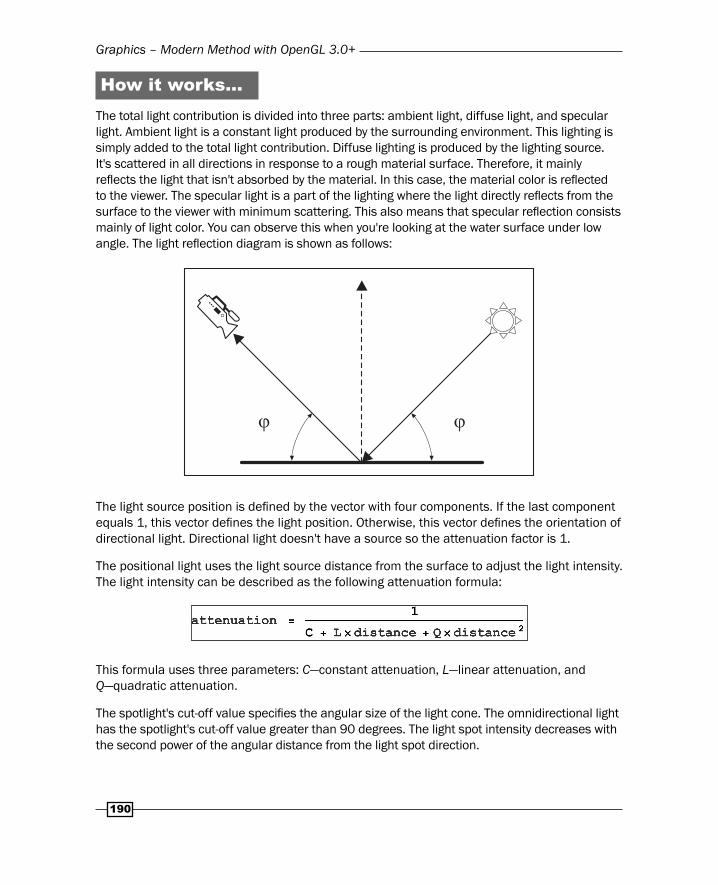
How it works…The total light contribution is divided into three parts: ambient light, diffuse light, and specular light. Ambient light is a constant light produced by the surrounding environment. This lighting is simply added to the total light contribution. Diffuse lighting is produced by the lighting source. It's scattered in all directions in response to a rough material surface. Therefore, it mainly refl ects the light that isn't absorbed by the material. In this case, the material color is refl ected to the viewer. The specular light is a part of the lighting where the light directly refl ects from the surface to the viewer with minimum scattering. This also means that specular refl ection consists mainly of light color. You can observe this when you're looking at the water surface under low angle. The light refl ection diagram is shown as follows:
� �
...
The light source position is defi ned by the vector with four components. If the last component equals 1, this vector defi nes the light position. Otherwise, this vector defi nes the orientation of directional light. Directional light doesn't have a source so the attenuation factor is 1.
The positional light uses the light source distance from the surface to adjust the light intensity. The light intensity can be described as the following attenuation formula:
This formula uses three parameters: C—constant attenuation, L—linear attenuation, and Q—quadratic attenuation.
The spotlight's cut-off value specifi es the angular size of the light cone. The omnidirectional light has the spotlight's cut-off value greater than 90 degrees. The light spot intensity decreases with the second power of the angular distance from the light spot direction.

Chapter 5
191
�
�
After these steps, you should have the fi nal attenuation value, which will be used on diffuse and specular refl ection.
Diffuse refl ection uses the surface normal vector and light direction vector to calculate the amount of light refl ected. Note that this type of refl ection is independent of camera position. The fi nal diffuse color is a result of multiplication of material color value with light color value and dot product of surface normal vector with the light direction vector. The dot product always produces values in a range (-1,1). If those two vectors are parallel, it results in a value 1. If they are perpendicular, it's 0. The negative values are produced when those two vectors enclose an angle greater than 90 degree. The fi nal value of diffusion color is modifi ed by attenuation value, so there are dark parts on the surface that are out of the light source range.
Specular refl ection occurs only on surface parts that refl ect light almost directly to the camera. The total amount of specular refl ection is modifi ed by the result of this formula:
Finally, the diffuse and specular refl ections are added to total light contribution on the selected part of the surface.
See also The Bumpmapping recipe
Graphics – Modern Method with OpenGL 3.0+
192
BumpmappingBumpmapping presents a way to increase a detail level without increasing the total polygon count. This technique relies on using normal maps applied to surfaces. Without this, each surface or polygon would have only one normal vector, and therefore, it would look like a fl at surface. It uses the term mapping because in addition to the basic texture map, it uses another texture that represents a normal map. A normal map contains normal vectors in tangent space and can be encoded as simple RGB texture, where each color component represents a normal vector component. It makes the surface look rough with bumps.
Bumpmap textures usually consist of grayscale image, where dark areas represent lower regions and lighter areas represent a higher region. Such images need to be converted into colorful normal map. You can use NVidia Texture Tools for Adobe Photoshop or a normal map plugin for the GIMP image editor. There's even a free online tool to do such conversion called NormalMap Online and it's available at the GitHub page http://cpetry.github.io/NormalMap-Online/.
Getting readyThis recipe uses a slightly modifi ed version of shaders from the previous recipe. While the vertex shader is almost the same, the fragment shader uses two texture units instead of one. The fi rst one is used for texture map and the second one is used for normal map. Therefore, you'll need to set up two texture units as follows:
local texture_target = gl_enum.GL_TEXTURE_2Dgl.ActiveTexture(gl_enum.GL_TEXTURE0)gl.BindTexture(texture_target, texture_map)
gl.ActiveTexture(gl_enum.GL_TEXTURE1)gl.BindTexture(texture_target, normal_map)
-- texturessetUniform('i', 'diffuseTexture', 0)setUniform('i', 'normalTexture', 1)
You'll also need to prepare lights in your scene. You can copy the light setup from the previous recipe about lighting basics.
You could try to apply a normal map as an ordinal texture, but soon you would've discovered certain artifacts in normal vector orientations. That's why you'll need to know triangle tangent vectors additionally to existing vertex attributes, such as a normal vector. These vectors describe the direction of the triangle plane. You'll need these vectors to apply vector correction in a normal map. Otherwise, the normal map would cause distortions and incorrect light refl ections. You can supply tangent vectors for each vertex by the vertex buffer.
Chapter 5
193
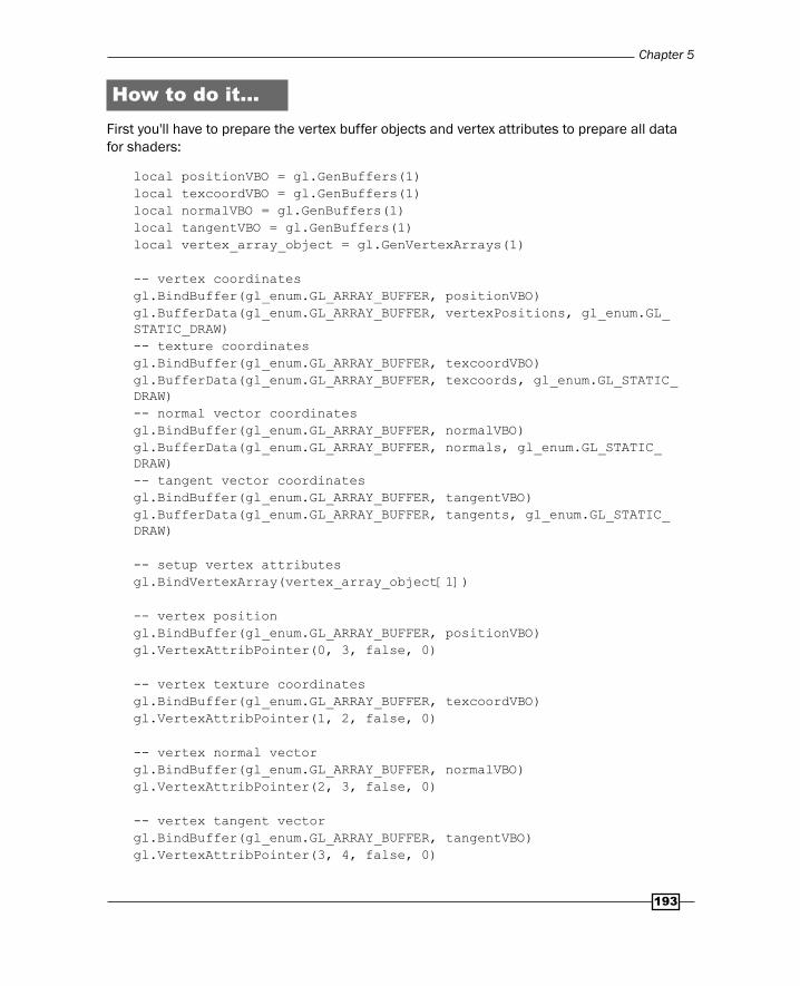
How to do it…First you'll have to prepare the vertex buffer objects and vertex attributes to prepare all data for shaders:
local positionVBO = gl.GenBuffers(1)local texcoordVBO = gl.GenBuffers(1)local normalVBO = gl.GenBuffers(1)local tangentVBO = gl.GenBuffers(1)local vertex_array_object = gl.GenVertexArrays(1)
-- vertex coordinatesgl.BindBuffer(gl_enum.GL_ARRAY_BUFFER, positionVBO)gl.BufferData(gl_enum.GL_ARRAY_BUFFER, vertexPositions, gl_enum.GL_STATIC_DRAW)-- texture coordinatesgl.BindBuffer(gl_enum.GL_ARRAY_BUFFER, texcoordVBO)gl.BufferData(gl_enum.GL_ARRAY_BUFFER, texcoords, gl_enum.GL_STATIC_DRAW)-- normal vector coordinatesgl.BindBuffer(gl_enum.GL_ARRAY_BUFFER, normalVBO)gl.BufferData(gl_enum.GL_ARRAY_BUFFER, normals, gl_enum.GL_STATIC_DRAW)-- tangent vector coordinatesgl.BindBuffer(gl_enum.GL_ARRAY_BUFFER, tangentVBO)gl.BufferData(gl_enum.GL_ARRAY_BUFFER, tangents, gl_enum.GL_STATIC_DRAW)
-- setup vertex attributesgl.BindVertexArray(vertex_array_object[1])
-- vertex positiongl.BindBuffer(gl_enum.GL_ARRAY_BUFFER, positionVBO)gl.VertexAttribPointer(0, 3, false, 0)
-- vertex texture coordinatesgl.BindBuffer(gl_enum.GL_ARRAY_BUFFER, texcoordVBO)gl.VertexAttribPointer(1, 2, false, 0)
-- vertex normal vectorgl.BindBuffer(gl_enum.GL_ARRAY_BUFFER, normalVBO)gl.VertexAttribPointer(2, 3, false, 0)
-- vertex tangent vectorgl.BindBuffer(gl_enum.GL_ARRAY_BUFFER, tangentVBO)gl.VertexAttribPointer(3, 4, false, 0)

Graphics – Modern Method with OpenGL 3.0+
194
You can get vertex positions, texture coordinates, and normal vectors easily. The diffi cult part is obtaining tangent vector.
Let's assume that you defi ne each polygon with a triangle. Therefore, each triangle has three points: A, B, and C as shown in the following diagram:
There are two vectors U and V that describe a plane defi ned by triangle points. You can compute these two vectors with the following code:
local U = { x = C.x - A.x, y = C.y - A.y, z = C.x - A.z}local V = { x = B.x - A.x, y = B.y - A.y, z = B.x - A.z}
You'll need to do the same with texture coordinates as well. Texture coordinate vectors will use letters S and T:
local S = { x = C.tx - A.tx, y = C.ty - A.ty,}local T = { x = B.tx - A.tx, y = B.ty - A.ty,}
Chapter 5
195
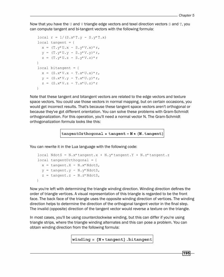
Now that you have the U and V triangle edge vectors and texel direction vectors S and T, you can compute tangent and bi-tangent vectors with the following formula:
local r = 1/(S.x*T.y - S.y*T.x)local tangent = { x = (T.y*U.x - S.y*V.x)*r, y = (T.y*U.y - S.y*V.y)*r, z = (T.y*U.z - S.y*V.z)*r}local bitangent = { x = (S.x*V.x - T.x*U.x)*r, y = (S.x*V.y - T.x*U.y)*r, z = (S.x*V.z - T.x*U.z)*r}
Note that these tangent and bitangent vectors are related to the edge vectors and texture space vectors. You could use those vectors in normal mapping, but on certain occasions, you would get incorrect results. That's because these tangent space vectors aren't orthogonal or because they've got different orientation. You can solve these problems with Gram-Schmidt orthogonalization. For this operation, you'll need a normal vector N. The Gram-Schmidt orthogonalization formula looks like this:
You can rewrite it in the Lua language with the following code:
local NdotS = N.x*tangent.x + N.y*tangent.Y + N.z*tangent.zlocal tangentOrthogonal = { x = tangent.X - N.x*NdotS, y = tangent.y - N.y*NdotS, z = tangent.z - N.z*NdotS,}
Now you're left with determining the triangle winding direction. Winding direction defi nes the order of triangle vertices. A visual representation of this triangle is regarded to be the front face. The back face of the triangle uses the opposite winding direction of vertices. The winding direction helps to determine the direction of the orthogonal tangent vector in the fi nal step. The invalid (opposite) direction of the tangent vector would reverse a texture on the triangle.
In most cases, you'll be using counterclockwise winding, but this can differ if you're using triangle strips, where the triangle winding alternates and this can pose a problem. You can obtain winding direction from the following formula:
Graphics – Modern Method with OpenGL 3.0+
196
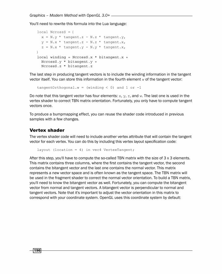
You'll need to rewrite this formula into the Lua language:
local NcrossS = { x = N.y * tangent.z - N.z * tangent.y, y = N.x * tangent.z - N.z * tangent.x, z = N.x * tangent.y - N.y * tangent.x,}local winding = NcrossS.x * bitangent.x + NcrossS.y * bitangent.y + NcrossS.z * bitangent.z
The last step in producing tangent vectors is to include the winding information in the tangent vector itself. You can store this information in the fourth element w of the tangent vector:
tangentOrthogonal.w = (winding < 0) and 1 or -1
Do note that this tangent vector has four elements: x, y, z, and w. The last one is used in the vertex shader to correct TBN matrix orientation. Fortunately, you only have to compute tangent vectors once.
To produce a bumpmapping effect, you can reuse the shader code introduced in previous samples with a few changes.
Vertex shaderThe vertex shader code will need to include another vertex attribute that will contain the tangent vector for each vertex. You can do this by including this vertex layout specifi cation code:
layout (location = 4) in vec4 VertexTangent;
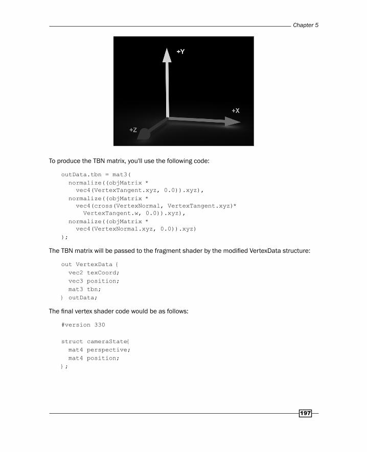
After this step, you'll have to compute the so-called TBN matrix with the size of 3 x 3 elements. This matrix contains three columns, where the fi rst contains the tangent vector, the second contains the bitangent vector and the last one contains the normal vector. This matrix represents a new vector space and is often known as the tangent space. The TBN matrix will be used in the fragment shader to correct the normal vector orientation. To build a TBN matrix, you'll need to know the bitangent vector as well. Fortunately, you can compute the bitangent vector from normal and tangent vectors. A bitangent vector is perpendicular to normal and tangent vectors. Note that it's important to adjust the vector orientation in this matrix to correspond with your coordinate system. OpenGL uses this coordinate system by default:
Chapter 5
197
To produce the TBN matrix, you'll use the following code:
outData.tbn = mat3( normalize((objMatrix * vec4(VertexTangent.xyz, 0.0)).xyz), normalize((objMatrix * vec4(cross(VertexNormal, VertexTangent.xyz)* VertexTangent.w, 0.0)).xyz), normalize((objMatrix * vec4(VertexNormal.xyz, 0.0)).xyz));
The TBN matrix will be passed to the fragment shader by the modifi ed VertexData structure:
out VertexData { vec2 texCoord; vec3 position; mat3 tbn;} outData;
The fi nal vertex shader code would be as follows:
#version 330
struct cameraState{ mat4 perspective; mat4 position;};
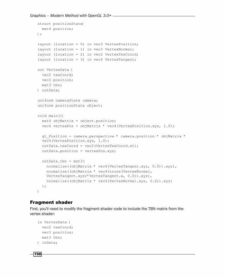
Graphics – Modern Method with OpenGL 3.0+
198
struct positionState{ mat4 position;};
layout (location = 0) in vec3 VertexPosition;layout (location = 1) in vec3 VertexNormal;layout (location = 2) in vec2 VertexTexCoord;layout (location = 3) in vec4 VertexTangent;
out VertexData { vec2 texCoord; vec3 position; mat3 tbn;} outData;
uniform cameraState camera;uniform positionState object;
void main(){ mat4 objMatrix = object.position; vec4 vertexPos = objMatrix * vec4(VertexPosition.xyz, 1.0);
gl_Position = camera.perspective * camera.position * objMatrix * vec4(VertexPosition.xyz, 1.0); outData.texCoord = vec2(VertexTexCoord.st); outData.position = vertexPos.xyz;
outData.tbn = mat3( normalize((objMatrix * vec4(VertexTangent.xyz, 0.0)).xyz), normalize((objMatrix * vec4(cross(VertexNormal, VertexTangent.xyz)*VertexTangent.w, 0.0)).xyz), normalize((objMatrix * vec4(VertexNormal.xyz, 0.0)).xyz) );}
Fragment shaderFirst, you'll need to modify the fragment shader code to include the TBN matrix from the vertex shader:
in VertexData { vec2 texCoord; vec3 position; mat3 tbn;} inData;
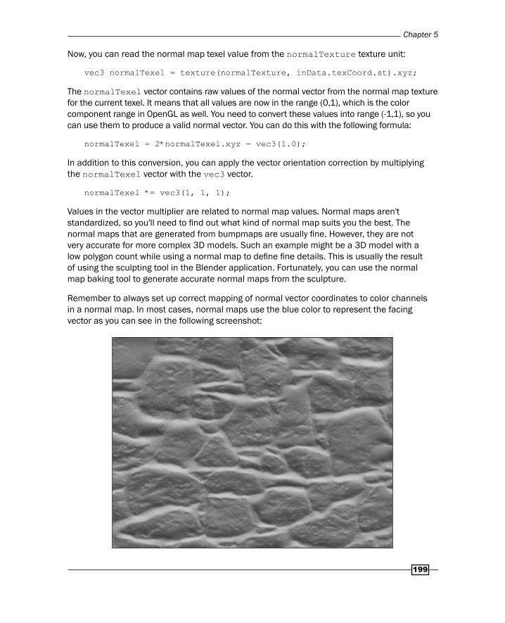
Chapter 5
199
Now, you can read the normal map texel value from the normalTexture texture unit:
vec3 normalTexel = texture(normalTexture, inData.texCoord.st).xyz;
The normalTexel vector contains raw values of the normal vector from the normal map texture for the current texel. It means that all values are now in the range (0,1), which is the color component range in OpenGL as well. You need to convert these values into range (-1,1), so you can use them to produce a valid normal vector. You can do this with the following formula:
normalTexel = 2*normalTexel.xyz - vec3(1.0);
In addition to this conversion, you can apply the vector orientation correction by multiplying the normalTexel vector with the vec3 vector.
normalTexel *= vec3(1, 1, 1);
Values in the vector multiplier are related to normal map values. Normal maps aren't standardized, so you'll need to fi nd out what kind of normal map suits you the best. The normal maps that are generated from bumpmaps are usually fi ne. However, they are not very accurate for more complex 3D models. Such an example might be a 3D model with a low polygon count while using a normal map to defi ne fi ne details. This is usually the result of using the sculpting tool in the Blender application. Fortunately, you can use the normal map baking tool to generate accurate normal maps from the sculpture.
Remember to always set up correct mapping of normal vector coordinates to color channels in a normal map. In most cases, normal maps use the blue color to represent the facing vector as you can see in the following screenshot:
Graphics – Modern Method with OpenGL 3.0+
200
After all these steps, you can produce the fi nal per-texel normal vector by converting the normalTexel vector into world space:
vec3 perTexelNormal = inData.tbn * normalize(normalTexel);
This vector can be used instead of the per-vertex normal vector in the processLighting function.
In the end, the fragment shader code would look like this:
#version 330
struct lightState { vec4 position; vec4 diffuse; vec4 specular; fl oat constantAttenuation, linearAttenuation, quadraticAttenuation; fl oat spotCutoff, spotExponent; vec3 spotDirection;};
struct materialState { vec4 ambient; vec4 diffuse; vec4 specular; fl oat shininess;};
struct cameraState{ mat4 perspective; mat4 translation; mat4 rotation;};
uniform sampler2D diffuseTexture;uniform sampler2D normalTexture;uniform cameraState camera;uniform materialState material;uniform vec4 sceneAmbient;
uniform int totalLights; uniform lightState lights[8];
in VertexData { vec2 texCoord;
Chapter 5
201
vec3 normal; vec3 position;} inData;
layout(location = 0) out vec4 diffuseColor;
vec4 processLighting(in materialState material, in vec3 surface, in vec3 normalDirection){ ...}
void main() { //local copy of material materialState localMaterial = material;
//texture texel vec4 texel = texture(diffuseTexture, inData.texCoord.st); localMaterial.diffuse *= texel;
//normalmap texel vec3 normalTexel = texture(normalTexture, inData.texCoord.st).xyz;
//normalize range normalTexel = (2*normalTexel.xyz - vec3(1.0));
//change normal vector orientation normalTexel *= vec3(-1, -1, 1);
//convert normal map vector into world space vec3 perTexelNormal = inData.tbn * normalize(normalTexel);
diffuseColor = processLighting( localMaterial, inData.position, normalize(perTexelNormal) );}
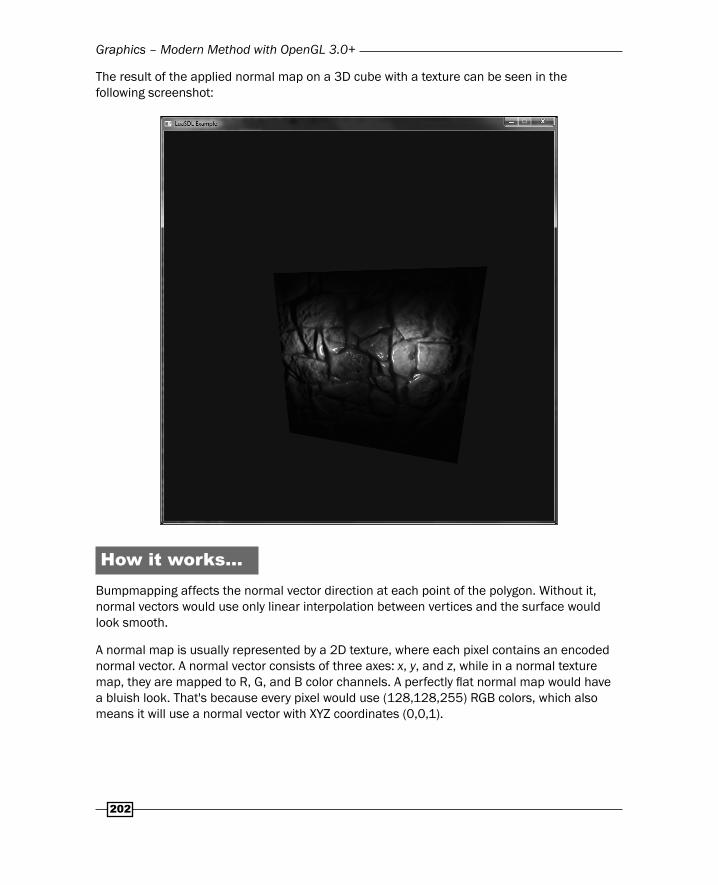
Graphics – Modern Method with OpenGL 3.0+
202
The result of the applied normal map on a 3D cube with a texture can be seen in the following screenshot:
How it works…Bumpmapping affects the normal vector direction at each point of the polygon. Without it, normal vectors would use only linear interpolation between vertices and the surface would look smooth.
A normal map is usually represented by a 2D texture, where each pixel contains an encoded normal vector. A normal vector consists of three axes: x, y, and z, while in a normal texture map, they are mapped to R, G, and B color channels. A perfectly fl at normal map would have a bluish look. That's because every pixel would use (128,128,255) RGB colors, which also means it will use a normal vector with XYZ coordinates (0,0,1).
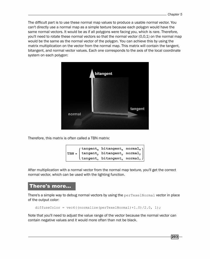
Chapter 5
203
The diffi cult part is to use these normal map values to produce a usable normal vector. You can't directly use a normal map as a simple texture because each polygon would have the same normal vectors. It would be as if all polygons were facing you, which is rare. Therefore, you'll need to rotate these normal vectors so that the normal vector (0,0,1) on the normal map would be the same as the normal vector of the polygon. You can achieve this by using the matrix multiplication on the vector from the normal map. This matrix will contain the tangent, bitangent, and normal vector values. Each one corresponds to the axis of the local coordinate system on each polygon:
Therefore, this matrix is often called a TBN matrix:
After multiplication with a normal vector from the normal map texture, you'll get the correct normal vector, which can be used with the lighting function.
There's more…There's a simple way to debug normal vectors by using the perTexelNormal vector in place of the output color:
diffuseColor = vec4((normalize(perTexelNormal)+1.0)/2.0, 1);
Note that you'll need to adjust the value range of the vector because the normal vector can contain negative values and it would more often than not be black.
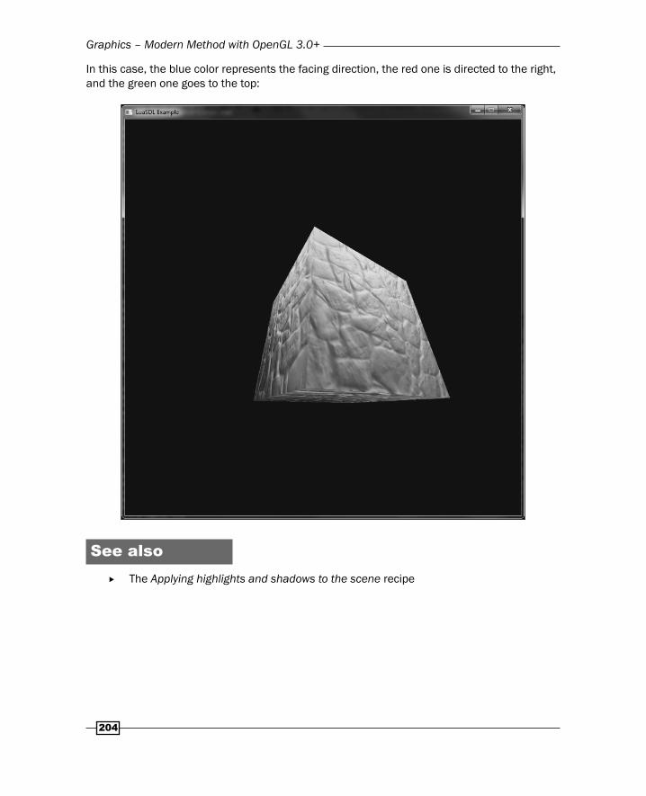
Graphics – Modern Method with OpenGL 3.0+
204
In this case, the blue color represents the facing direction, the red one is directed to the right, and the green one goes to the top:
See also The Applying highlights and shadows to the scene recipe

Where to buy this book You can buy Lua Game Development Cookbook from the Packt Publishing website.
Alternatively, you can buy the book from Amazon, BN.com, Computer Manuals and most internet
book retailers.
Click here for ordering and shipping details.
www.PacktPub.com
Stay Connected:
Get more information Lua Game Development Cookbook