Embed Size (px)
Citation preview
dsp tips & tricks
IEEE SIGNAL PROCESSING MAGAZINE70 NOVEMBER 2004
new, and improved,image coding standard
has been developed,and it’s calledJPEG2000. In this
article we describe the most impor-tant parameters of this new standardand present several “tips and tricks”to help resolve design tradeoffs thatJPEG2000 application developersare likely to encounter in practice.
JPEG2000 is the state-of-the-artimage coding standard that resultedfrom the joint efforts of theInternational Standards Organization(ISO) and the InternationalTelecommunications Union (ITU)[1]; “JPEG” in JPEG2000 is anacronym for Joint Picture ExpertsGroup. The new standard outper-forms the older JPEG standard byapproximately 2 dB of peak signal-to-noise ratio (PSNR) for severalimages across all compression ratios[1]. Two primary reasons forJPEG2000’s superior performanceare the wavelet transform andembedded block coding with opti-mal truncation (EBCOT) [3]. Thestandard is organized in 12 parts [4].Part 1 specifies the core coding sys-tem while Part 2 adds some featuresand more sophistication to the core.Part 3 describes motion JPEG, arudimentary form of video codingwhere each JPEG2000 image is aframe. Other important parts of thestandard include: security aspects,interactive protocols and applicationprogram interfaces for networkaccess, and wireless transmission ofJPEG2000 images.
We limit our discussion to thoseparameters specified in the core pro-cessing system, Part 1 of theJPEG2000 standard. A comprehen-sive list of the parameters is depictedin Table 1; they are given in theorder that they are encountered inthe encoder.
The chosen values for some ofthese parameters are dictated by thetarget application. For example,most applications require the com-pressed image to be reconstructedat the original bit depth. The pro-gression order and the number ofquality layers are also determinedby the requirements of the applica-tion. Other parameters, like themagnitude refinement codingmethod or the MQ-code termina-tion method, minimally impact thequality of the compressed image,the size of the compressed data, orthe complexity of the encoder. Foreach parameter, JPEG2000 pro-vides either a recommendation or adefault; this represents a good, ini-tial choice for the parameter. Inthis article, we elaborate on sixparameters for which there exists awide range of acceptable values,and those chosen values significant-ly impact compressed image qualityand codec efficiency. The sixparameters are 2–3, 5, 7–8, and 13in Table 1. We discuss the merits ofthe choices for these parametersbased on the following perfor-mance measures: compressed datasize, compressed image quality,computation time, and memoryrequirements.
Tile SizeJPEG2000 allows an image to bedivided into rectangular blocks ofthe same size called “tiles,” and eachtile is encoded independently. Tilesize is a coding parameter that isexplicitly specified in the compresseddata. By tiling an image, the distinctfeatures in the image can be separat-ed into different tiles; this enables amore efficient encoding process. Forexample, a composite image com-prised of a photograph and text canbe divided into tiles that separate thetwo; then two very differentapproaches (e.g., original bit depthand five-level transform for the pho-tograph, and bit depth of one- andzero-level transform for the text) areused to obtain significantly betteroverall coding efficiency.
Choosing the tile size for animage is an important encodertradeoff. Figure 1 shows the“Woman” image compressed at100:1, using two different tile sizes:(a) 64 × 64 and (b) 256 × 256.Figure 1(a) (corresponding to thesmaller tile size) is corrupted by
Krishnaraj Varma and Amy Bell
JPEG2000—Choices and Tradeoffs for Encoders
“DSP Tips and Tricks” introducespractical tips and tricks of design andimplementation of signal processingalgorithms so that you may be ableto incorporate them into yourdesigns. We welcome readers whoenjoy reading this column to submittheir contributions. Contact AssociateEditors Rick Lyons ([email protected])or Amy Bell ([email protected]).
A
1053-5888/04/$20.00©2004IEEE

IEEE SIGNAL PROCESSING MAGAZINENOVEMBER 2004 71
blocking artifacts—the imageappears to be composed of rectan-gles, particularly in smooth areaslike the woman’s cheeks and fore-head. This is a common observationat moderate to high compressionratios; however, at low compressionratios (<32:1) a small tile size intro-duces minimal blocking artifacts.Alternatively, a large tile size pre-sents two challenges. First, if theencoder/decoder processes anentire tile at once, this may requireprohibitively large memory. Second,features may not be isolated intoseparate tiles, and the encoding effi-ciency suffers.
Recommendation: Do not tilesmall images (≤ 512 × 512). Tilelarge images with a tile size that sep-arates the features, but at high com-pression ratios, use a tile size greaterthan or equal to 256 × 256 to avoidblocking artifacts.
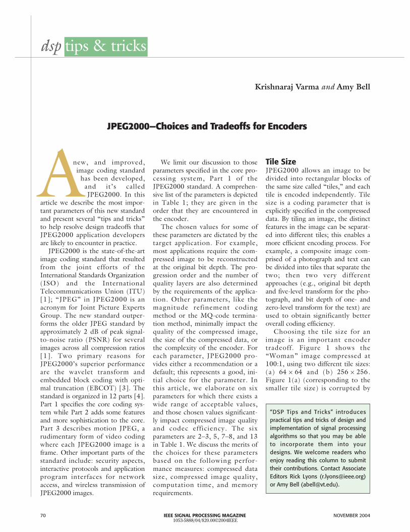
Color SpaceWe humans view color images in thered, green, and blue (RGB) colorspace. However, for most colorimages, the luminance, chrominanceblue, and chrominance red (YCbCr)color space concentrates image energyas well or better than RGB. In RGB,energy is more evenly distributedacross the three components; howev-er, in YCbCr, most of the energyresides in the luminance (Y) compo-nent. For example, the two chromi-nance components typically accountfor only 20% of the bits in the com-pressed JPEG2000 image [5].However, if the RGB image is com-posed of mostly one color, then theYCbCr representation cannot improveon the efficient energy compaction inRGB. For these color images, RGBcompression quality is superior toYCbCr compression quality.
Figure 2 depicts the “lighthouse”image, compressed at 32:1 in the(a) RGB color space and in the (b)YCbCr color space. Compression inYCbCr shows a higher quality com-
pressed image in (b): the roof edge,grass, and cloud texture, and otherdetails are closer to the original,uncompressed image than in (a).
Recommendation: Convert theoriginal, uncompressed RGB colorimage to the YCbCr color spaceexcept when the RGB image primar-ily consists of one color component.
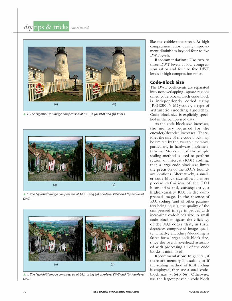
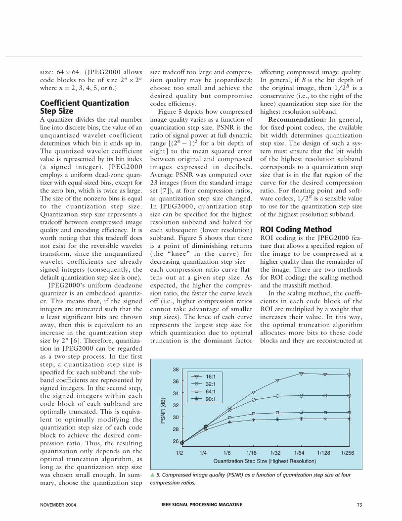
Number of WaveletTransform LevelsEach image color component istransformed into the waveletdomain using the two-dimensionaldiscrete wavelet transform (DWT).JPEG2000 allows the number oflevels in the DWT to be specified.By increasing the number of DWTlevels, we examine the lower fre-
quencies at increasingly finer resolu-tion, thereby packing more energyinto fewer wavelet coefficients.Thus, we expect compression per-formance to improve as the numberof levels increases.
Figure 3 shows the “goldhill”image compressed at 16:1 using (a)a one-level DWT and (b) a two-level DWT. The difference in quali-ty between the two is minimal. Atlow compression ratios, qualityimprovement diminishes beyondtwo to three DWT levels. On theother hand, Figure 4 shows thesame image compressed at 64:1using (a) a one-level and (b) a four-level DWT. In this case, the superi-or quality of the four-level DWT isevident—particularly in the details
1) Reconstructed image bit depth 9) Perceptual weights2) Tile size 10) Block coding parameters:3) Color space a) Magnitude refinement coding4) Reversible or irreversible transform method5) Number of wavelet transform levels b) MQ code termination method6) Precinct size 11) Progression order7) Code-block size 12) Number of quality layers8) Coefficient quantization step size 13) Region of interest coding method
Table 1. Parameters in part 1 of the JPEG2000 standard.
▲ 1. The “woman” image compressed at 100:1 with tile size (a) 64× 64 and (b) 256× 256.
(a) (b)
dsp tips & tricks continued
IEEE SIGNAL PROCESSING MAGAZINE72 NOVEMBER 2004
like the cobblestone street. At highcompression ratios, quality improve-ment diminishes beyond four to fiveDWT levels.
Recommendation: Use two tothree DWT levels at low compres-sion ratios and four to five DWTlevels at high compression ratios.
Code-Block SizeThe DWT coefficients are separatedinto nonoverlapping, square regionscalled code blocks. Each code blockis independently coded usingJPEG2000’s MQ-coder, a type ofarithmetic encoding algorithm.Code-block size is explicitly speci-fied in the compressed data.
As the code-block size increases,the memory required for theencoder/decoder increases. There-fore, the size of the code block maybe limited by the available memory,particularly in hardware implemen-tations. Moreover, if the simplescaling method is used to performregion of interest (ROI) coding,then a large code-block size limitsthe precision of the ROI’s bound-ary locations. Alternatively, a small-er code-block size allows a moreprecise definition of the ROIboundaries and, consequently, ahigher-quality ROI in the com-pressed image. In the absence ofROI coding (and all other parame-ters being equal), the quality of thecompressed image improves withincreasing code-block size. A smallcode block mitigates the efficiencyof the MQ coder that, in turn,decreases compressed image quali-ty. Finally, encoding/decoding isfaster for a larger code-block size,since the overall overhead associat-ed with processing all of the codeblocks is minimized.
Recommendation: In general, ifthere are memory limitations or ifthe scaling method of ROI codingis employed, then use a small code-block size (< 64 × 64). Otherwise,use the largest possible code-block
▲ 2. The “lighthouse” image compressed at 32:1 in (a) RGB and (b) YCbCr.
▲ 3. The “goldhill” image compressed at 16:1 using (a) one-level DWT and (b) two-levelDWT.
(a) (b)
(a) (b)
▲ 4. The “goldhill” image compressed at 64:1 using (a) one-level DWT and (b) four-levelDWT.
(a) (b)
IEEE SIGNAL PROCESSING MAGAZINENOVEMBER 2004 73
size: 64 × 64. (JPEG2000 allowscode blocks to be of size 2n × 2n
where n = 2, 3, 4, 5, or 6.)
Coefficient QuantizationStep Size A quantizer divides the real numberline into discrete bins; the value of anunquantized wavelet coefficientdetermines which bin it ends up in.The quantized wavelet coefficientvalue is represented by its bin index(a signed integer). JPEG2000employs a uniform dead-zone quan-tizer with equal-sized bins, except forthe zero bin, which is twice as large.The size of the nonzero bins is equalto the quantization step size.Quantization step size represents atradeoff between compressed imagequality and encoding efficiency. It isworth noting that this tradeoff doesnot exist for the reversible wavelettransform, since the unquantizedwavelet coefficients are alreadysigned integers (consequently, thedefault quantization step size is one).
JPEG2000’s uniform deadzonequantizer is an embedded quantiz-er. This means that, if the signedintegers are truncated such that then least significant bits are thrownaway, then this is equivalent to anincrease in the quantization stepsize by 2n [6]. Therefore, quantiza-tion in JPEG2000 can be regardedas a two-step process. In the firststep, a quantization step size isspecified for each subband: the sub-band coefficients are represented bysigned integers. In the second step,the signed integers within eachcode block of each subband areoptimally truncated. This is equiva-lent to optimally modifying thequantization step size of each codeblock to achieve the desired com-pression ratio. Thus, the resultingquantization only depends on theoptimal truncation algorithm, aslong as the quantization step sizewas chosen small enough. In sum-mary, choose the quantization step
size tradeoff too large and compres-sion quality may be jeopardized;choose too small and achieve thedesired quality but compromisecodec efficiency.
Figure 5 depicts how compressedimage quality varies as a function ofquantization step size. PSNR is theratio of signal power at full dynamicrange [(28 − 1)2 for a bit depth ofeight] to the mean squared errorbetween original and compressedimages expressed in decibels.Average PSNR was computed over23 images (from the standard imageset [7]), at four compression ratios,as quantization step size changed.In JPEG2000, quantization stepsize can be specified for the highestresolution subband and halved foreach subsequent (lower resolution)subband. Figure 5 shows that thereis a point of diminishing returns(the “knee” in the curve) fordecreasing quantization step size—each compression ratio curve flat-tens out at a given step size. Asexpected, the higher the compres-sion ratio, the faster the curve levelsoff (i.e., higher compression ratioscannot take advantage of smallerstep sizes). The knee of each curverepresents the largest step size forwhich quantization due to optimaltruncation is the dominant factor
affecting compressed image quality.In general, if B is the bit depth ofthe original image, then 1/2B is aconservative (i.e., to the right of theknee) quantization step size for thehighest resolution subband.
Recommendation: In general,for fixed-point codecs, the availablebit width determines quantizationstep size. The design of such a sys-tem must ensure that the bit widthof the highest resolution subbandcorresponds to a quantization stepsize that is in the flat region of thecurve for the desired compressionratio. For floating point and soft-ware codecs, 1/2B is a sensible valueto use for the quantization step sizeof the highest resolution subband.
ROI Coding MethodROI coding is the JPEG2000 fea-ture that allows a specified region ofthe image to be compressed at ahigher quality than the remainder ofthe image. There are two methodsfor ROI coding: the scaling methodand the maxshift method.
In the scaling method, the coeffi-cients in each code block of theROI are multiplied by a weight thatincreases their value. In this way,the optimal truncation algorithmallocates more bits to these codeblocks and they are reconstructed at
▲ 5. Compressed image quality (PSNR) as a function of quantization step size at fourcompression ratios.
1/2 1/4 1/8 1/16 1/32 1/64 1/128 1/256
26
28
30
32
34
36
38
Quantization Step Size (Highest Resolution)
PS
NR
(dB
)
16:132:164:190:1
dsp tips & tricks continued
IEEE SIGNAL PROCESSING MAGAZINE74 NOVEMBER 2004
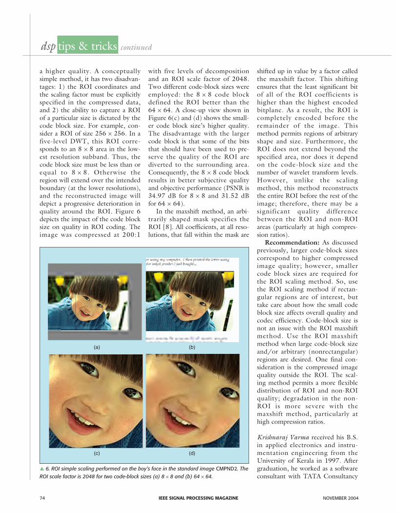
a higher quality. A conceptuallysimple method, it has two disadvan-tages: 1) the ROI coordinates andthe scaling factor must be explicitlyspecified in the compressed data,and 2) the ability to capture a ROIof a particular size is dictated by thecode block size. For example, con-sider a ROI of size 256 × 256. In afive-level DWT, this ROI corre-sponds to an 8 × 8 area in the low-est resolution subband. Thus, thecode block size must be less than orequal to 8 × 8. Otherwise theregion will extend over the intendedboundary (at the lower resolutions),and the reconstructed image willdepict a progressive deterioration inquality around the ROI. Figure 6depicts the impact of the code blocksize on quality in ROI coding. Theimage was compressed at 200:1
with five levels of decompositionand an ROI scale factor of 2048.Two different code-block sizes wereemployed: the 8 × 8 code blockdefined the ROI better than the64 × 64. A close-up view shown inFigure 6(c) and (d) shows the small-er code block size’s higher quality.The disadvantage with the largercode block is that some of the bitsthat should have been used to pre-serve the quality of the ROI arediverted to the surrounding area.Consequently, the 8 × 8 code blockresults in better subjective qualityand objective performance (PSNR is34.97 dB for 8 × 8 and 31.52 dBfor 64 × 64).
In the maxshift method, an arbi-trarily shaped mask specifies theROI [8]. All coefficients, at all reso-lutions, that fall within the mask are
shifted up in value by a factor calledthe maxshift factor. This shiftingensures that the least significant bitof all of the ROI coefficients ishigher than the highest encodedbitplane. As a result, the ROI iscompletely encoded before theremainder of the image. Thismethod permits regions of arbitraryshape and size. Furthermore, theROI does not extend beyond thespecified area, nor does it dependon the code-block size and thenumber of wavelet transform levels.However, unlike the scalingmethod, this method reconstructsthe entire ROI before the rest of theimage; therefore, there may be asignificant quality differencebetween the ROI and non-ROIareas (particularly at high compres-sion ratios).
Recommendation: As discussedpreviously, larger code-block sizescorrespond to higher compressedimage quality; however, smallercode block sizes are required forthe ROI scaling method. So, usethe ROI scaling method if rectan-gular regions are of interest, buttake care about how the small codeblock size affects overall quality andcodec efficiency. Code-block size isnot an issue with the ROI maxshiftmethod. Use the ROI maxshiftmethod when large code-block sizeand/or arbitrary (nonrectangular)regions are desired. One final con-sideration is the compressed imagequality outside the ROI. The scal-ing method permits a more flexibledistribution of ROI and non-ROIquality; degradation in the non-ROI is more severe with themaxshift method, particularly athigh compression ratios.
Krishnaraj Varma received his B.S.in applied electronics and instru-mentation engineering from theUniversity of Kerala in 1997. Aftergraduation, he worked as a softwareconsultant with TATA Consultancy
▲ 6. ROI simple scaling performed on the boy’s face in the standard image CMPND2. TheROI scale factor is 2048 for two code-block sizes (a) 8× 8 and (b) 64× 64.
(a) (b)
(c) (d)
Services. Varma received his M.S. inelectrical engineering from VirginiaTech in 2002. He is currently pur-suing a Ph.D. in electrical engineer-ing at Virginia Tech. His researchinterests are in the areas of digitalsignal processing, image processing,and communications.
Amy Bell is an associate professor inthe department of electrical andcomputer engineering at VirginiaTech. She received her Ph.D. in elec-trical engineering from theUniversity of Michigan. She con-ducts research in wavelet image com-pression, embedded systems, andbioinformatics. She is the recipient of
a 1999 NSF CAREER award and a2002 NSF Information TechnologyResearch award. She is an associateeditor of IEEE Signal ProcessingMagazine and her “best results” todate include Jacob and Henry: a col-laboration with her husband.
References[1] International Telecommunication Union, “ITU
T.800: JPEG2000 image coding system Part 1, ITUstd,” July 2002 [Online]. Available: www.itu.org
[2] A. Skodras, C. Christopoulos, and T. Ebrahimi,“The JPEG2000 still image compression stan-dard,” IEEE Signal Processing Mag., vol. 18,no. 5, pp. 36–58, Sept. 2001.
[3] D. Taubman, “High performance scalable imagecompression with EBCOT,” IEEE Trans. ImageProcessing, vol. 9, no. 7, pp. 1158–1170, 2000.
[4] Elysium Ltd., Information about theJPEG2000 Standard [Online]. Available:http://www.jpeg.org/ jpeg2000/index.html
[5] D.S. Taubman and M.W. Marcellin, JPEG2000–Image Compression Fundamentals,Standards and Practice. Norwell, MA: Kluwer,2002.
[6] M. Marcellin, M. Lepley, A. Bilgin, T. Flohr,T. Chinen, and J. Kasner, “An overview ofquantization in JPEG2000,” Signal Processing:Image Commun., vol. 17, no. 1, pp. 73–84,2002.
[7] “ITU T.24: Standardized digitized image set,ITU Std.,” June 1998 [Online]. Available:www.itu.org
[8] J. Askelöf, M.L. Carlander, and C. Christopoulos,“Region of interest coding in JPEG2000,”Signal Processing: Image Commun., vol. 17,no. 1, pp. 105–111, 2002.
IEEE SIGNAL PROCESSING MAGAZINENOVEMBER 2004 75
correction
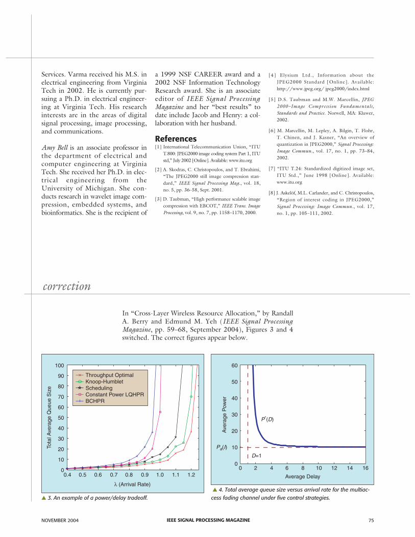
In “Cross-Layer Wireless Resource Allocation,” by RandallA. Berry and Edmund M. Yeh (IEEE Signal ProcessingMagazine, pp. 59–68, September 2004), Figures 3 and 4switched. The correct figures appear below.
▲ 4. Total average queue size versus arrival rate for the multiac-cess fading channel under five control strategies.
Pa(I)
Ave
rage
Pow
er
60
50
40
30
20
10
00 2 4 6 8 10 12 14 16
D=1
P*(D)
Average Delay
▲ 3. An example of a power/delay tradeoff.
Tota
l Ave
rage
Que
ue S
ize
100
90
80
70
60
50
40
30
20
10
00.4 0.5 0.6 0.7 0.8 0.9 1.0 1.1 1.2
λ (Arrival Rate)
Throughput OptimalKnoop-HumbletSchedulingConstant Power LQHPRBCHPR


![Video Over IP with JPEG2000 Reference Design · 2021. 6. 29. · JPEG2000 Decoder The JPEG2000 Decoder core [Ref 7] decompresses a JPEG2000 stream received from the 1Gb Ethernet cable](https://img.pdfslide.us/doc/110x75/61327ec2dfd10f4dd73a7ca8/video-over-ip-with-jpeg2000-reference-design-2021-6-29-jpeg2000-decoder-the.jpg)