Embed Size (px)
Citation preview
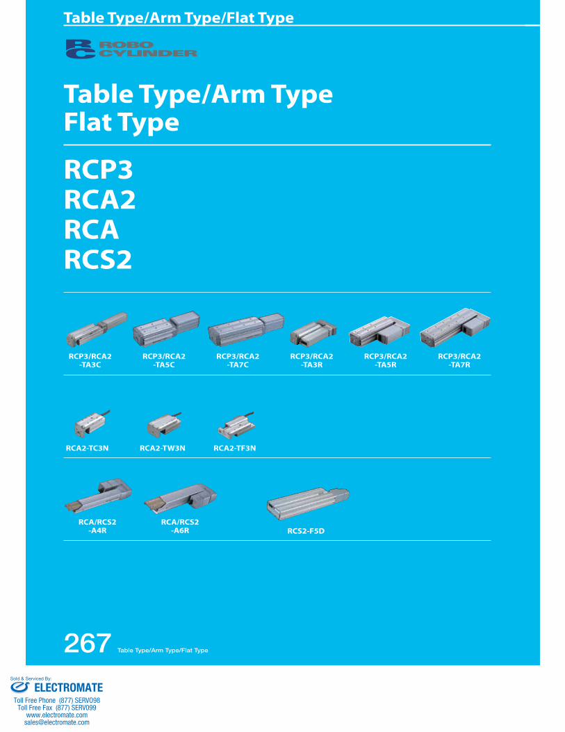
Table Type/Arm TypeFlat Type
RCP3RCA2RCARCS2
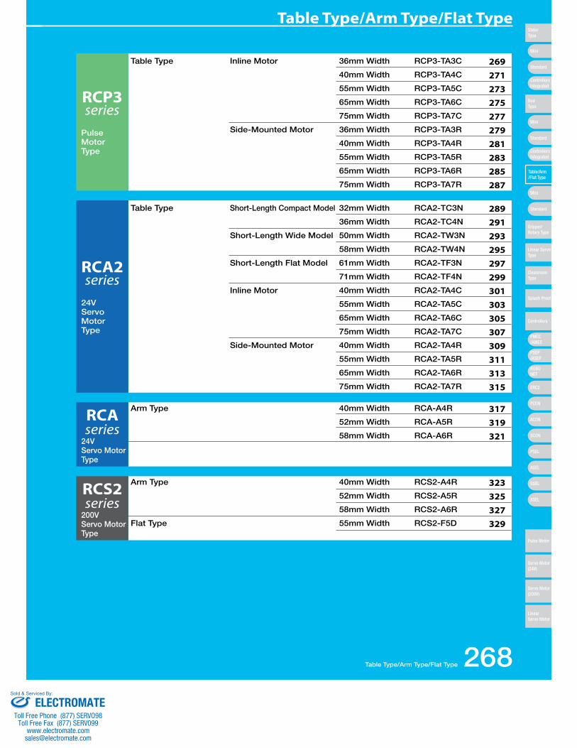
RCA2-TC3N RCA2-TW3N RCA2-TF3N
RCP3/RCA2-TA3C
RCA/RCS2-A4R
RCP3/RCA2-TA5C
RCA/RCS2-A6R
RCP3/RCA2-TA7C
RCP3/RCA2-TA3R
RCP3/RCA2-TA5R
RCP3/RCA2-TA7R
RCS2-F5D
267 Table Type/Arm Type/Flat Type
Table Type/Arm Type/Flat Type
ELECTROMATEToll Free Phone (877) SERVO98
Toll Free Fax (877) SERV099www.electromate.com
Sold & Serviced By:
RCP3 series
Pulse MotorType
RCA2 series
24VServo MotorType
RCA series
24VServo MotorType
RCS2 series
200VServo MotorType
269271273275277279281283285287
289291293295297299301303305307309311313315
317319321
323325327329
Table Type Inline Motor 36mm Width RCP3-TA3C
40mm Width RCP3-TA4C
55mm Width RCP3-TA5C
65mm Width RCP3-TA6C
75mm Width RCP3-TA7C
Side-Mounted Motor 36mm Width RCP3-TA3R
40mm Width RCP3-TA4R
55mm Width RCP3-TA5R
65mm Width RCP3-TA6R
75mm Width RCP3-TA7R
Table Type Short-Length Compact Model 32mm Width RCA2-TC3N
36mm Width RCA2-TC4N
Short-Length Wide Model 50mm Width RCA2-TW3N
58mm Width RCA2-TW4N
Short-Length Flat Model 61mm Width RCA2-TF3N
71mm Width RCA2-TF4N
Inline Motor 40mm Width RCA2-TA4C
55mm Width RCA2-TA5C
65mm Width RCA2-TA6C
75mm Width RCA2-TA7C
Side-Mounted Motor 40mm Width RCA2-TA4R
55mm Width RCA2-TA5R
65mm Width RCA2-TA6R
75mm Width RCA2-TA7R
Arm Type 40mm Width RCA-A4R
52mm Width RCA-A5R
58mm Width RCA-A6R
Arm Type 40mm Width RCS2-A4R
52mm Width RCS2-A5R
58mm Width RCS2-A6R
Flat Type 55mm Width RCS2-F5D
Table Type/Arm Type/Flat Type 268
Table Type/Arm Type/Flat Type
Mini
Mini
PSEP/ASEP
PMEC/AMEC
ROBONET
ERC2
PCON
ACON
SCON
PSEL
ASEL
SSEL
XSEL
Standard
Mini
Standard
Standard
ControllersIntegrated
ControllersIntegrated
SliderType
RodType
Table/Arm/Flat Type
Gripper/Rotary Type
Linear ServoType
Cleanroom Type
Splash Proof
Controllers
Pulse Motor
Servo Motor (24V)
Servo Motor (200V)
LinearServo Motor
ELECTROMATEToll Free Phone (877) SERVO98
Toll Free Fax (877) SERV099www.electromate.com
Sold & Serviced By:
(Note 2) See page A-66 for pushing force graphs.
Bal
l Scr
ewLead(mm)
Feed Screw Horizontal (kg) Vertical (kg)
Max. Load Capacity (Note 1) Positioning Repeatability
(mm)
Maximum Push Force (N)
(Note 2)Model
Stroke(mm)
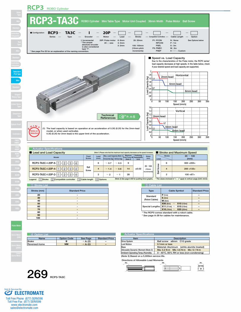
RCP3-TA3C-I-20P-6- 1 - 2 - 3 - 4
RCP3-TA3C-I-20P-4- 1 - 2 - 3 - 4
RCP3-TA3C-I-20P-2- 1 - 2 - 3 - 4
Ball
Screw
~ 0.76
~ 1.44
~ 22
~ 0.3
~ 0.6
~ 1
9
14
28
20~100(10mm
increments)
±0.02
■ Speed vs. Load CapacityDue to the characteristics of the Pulse motor, the RCP3 series' load capacity decreases at high speeds. In the table below, check if your desired speed and load capacity are supported.
0 50 100 150 200 250 300 350Speed (mm/s)
0
0.25
0.5
0.75
1.0
1.25
1.5
1.75
2
Horizontal2mm lead
4mm lead
6mm lead
1.41.4
0.7
Load
Cap
acity
(kg)
0 50 100 150 200 250 300 350Speed (mm/s)
0
0.2
0.4
0.6
0.8
1.0
1.2
1.4
1.6
Vertical
0.30.3
0.7
Load
Cap
acity
(kg)
2mm lead
4mm lead
6mm lead
1 Stroke List 3 Cable List
4 Option List
RCP3-TA3C ROBO Cylinder Mini Table Type Motor Unit Coupled 36mm Width Pulse Motor Ball Screw
Legend 1 Stroke 2 Compatible controller 3 Cable length 4 Options
Actuator Specifications
Stroke
Lead
20~ 100(mm)
300 <200>
200 <133>
100 <67>
6
4
2
■ Lead and Load Capacity ■ Stroke and Maximum Speed(Note 1) Please note that the maximum load capacity decreases as the speed increases.
(Unit: mm/s)
* See page Pre-35 for an explanation of the naming convention.
20P: Pulse motor20 □ size
I: Incremental* The simple absolute encoder is also considered type "I".
N : NoneP : 1mS : 3mM : 5mX□□ : Custom
See Options below 6 : 6mm 4 : 4mm 2 : 2mm
■ Configuration: RCP3 TA3C I 20PSeries Type Encoder Motor Lead Stroke Compatible Controllers Cable Length Option
Special Lengths
Type Standard PriceCable Symbol
Standard
(Robot Cables)
P (1m)
S (3m)
M (5m)
X06 (6m) ~ X10 (10m)
X11 (11m) ~ X15 (15m)
X16 (16m) ~ X20 (20m)
––––––
---------
2030405060708090
100
Name Standard PriceOption Code See PageB
NM→ A-25→ A-33
BrakeReversed-home
––
(1) The load capacity is based on operation at an acceleration of 0.3G (0.2G for the 2mm-lead model, or when used vertically).0.3G (0.2G for 2mm lead) is the upper limit of the acceleration.
P
O I N T
Notes on Selection
* The values enclosed in "< >" apply to vertical usage.
* The RCP3 comes standard with a robot cable.* See page A-39 for cables for maintenance.
Actuator Specifications
DescriptionItemBall screw ø6mm C10 grade 0.1mm or lessMaterial: Aluminum (white alumite treated)Ma: 3.2 N∙m Mb: 4.6 N∙m Mc: 5.1 N∙m0~40°C, 85% RH or less (non-condensing)
Drive SystemLost MotionBaseAllowable Dynamic Moment (Note 3)Ambient Operating Temp./Humidity
(Note 3) Based on a 5,000km service life.
P1: PCON RPCON PSEL
P3: PMEC PSEP
20: 20mm〜
100: 100mm (10mm pitch increments)
P. A-5Technical References
Stroke (mm) Standard Price
Ma Mb Mc
Directions of Allowable Load Moments
269 RCP3-TA3C
RCP3 ROBO Cylinder
Mini
Mini
PSEP/ASEP
PMEC/AMEC
ROBONET
ERC2
PCON
ACON
SCON
PSEL
ASEL
SSEL
XSEL
Standard
Mini
Standard
Standard
ControllersIntegrated
ControllersIntegrated
RodType
Table/Arm/Flat Type
Gripper/Rotary Type
Linear ServoType
Cleanroom Type
Splash Proof
Controllers
Pulse Motor
Servo Motor (24V)
Servo Motor (200V)
LinearServo Motor
SliderType
ELECTROMATEToll Free Phone (877) SERVO98
Toll Free Fax (877) SERV099www.electromate.com
Sold & Serviced By:
Moment offsetreference position10
.5
28.5
3-M4 depth 6 24
105
3336
4.5
2441
ø3H7 depth 3.5(from top of table)
16
12 G×40 H-M3 depth 5Motor-encodercable connector*1
3H7
dept
h 3.
5(fr
om to
p of
tabl
e)
40(between reamer hole
and oblong hole)
4
38
If equipped with a brake
3229
35 7.4
7.5
30(M
otor
sec
tion
heig
ht)
3.5 18
Secure at least 100L102.5
2623
ME*2Home
8
ST
SEME3
12 18.5
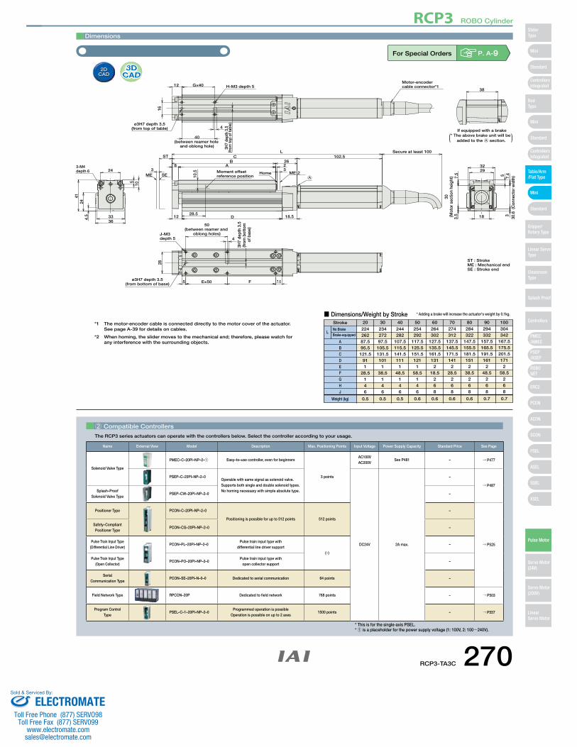
ST : Stroke
30.6
(C
onne
ctor
wid
th)
AB
C
D
3H7
dept
h 3.
5(fr
om b
otto
m
of b
ase)
4
50(between reamer and
oblong holes)J-M3 depth 5
28
ø3H7 depth 3.5(from bottom of base) 5 E×50 F 7.5
* The above brake unit will be added to the A section.( )
A
ME : Mechanical endSE : Stroke end
*1 The motor-encoder cable is connected directly to the motor cover of the actuator.See page A-39 for details on cables.
*2 When homing, the slider moves to the mechanical end; therefore, please watch for any interference with the surrounding objects.
Dimensions
■ Dimensions/Weight by StrokeStroke
LNo BrakeBrake-equipped
ABCDEFGHJ
Weight (kg)
22426287.595.5121.5
911
28.5146
0.5
23427297.5105.5131.5101
138.5
146
0.5
244282
107.5115.5141.5111
148.5
146
0.5
254292
117.5125.5151.5121
158.5
146
0.6
264302
127.5135.5161.5131
218.5
268
0.6
274312
137.5145.5171.5141
228.5
268
0.6
284322
147.5155.5181.5151
238.5
268
0.6
294332
157.5165.5191.5161
248.5
268
0.7
304342
167.5175.5201.5171
258.5
268
0.7
20 30 40 50 60 70 80 90 100
* Adding a brake will increase the actuator's weight by 0.1kg.
For Special Orders P. A-9
2 Compatible Controllers
The RCP3 series actuators can operate with the controllers below. Select the controller according to your usage.
Name External View Model Description Max. Positioning Points Input Voltage Power Supply Capacity Standard Price See Page
Solenoid Valve Type
PMEC–C–20PI–NP–2–1 Easy–to–use controller, even for beginners
3 points
AC100VAC200V
See P481 – → P477
PSEP–C–20PI–NP–2–0Operable with same signal as solenoid valve.Supports both single and double solenoid types.No homing necessary with simple absolute type.
DC24V 2A max.
–
→ P487Splash–Proof
Solenoid Valve TypePSEP–CW–20PI–NP–2–0 –
Positioner Type PCON–C–20PI–NP–2–0
Positioning is possible for up to 512 points 512 points
–
→ P525
Safety–Compliant Positioner Type
PCON–CG–20PI–NP–2–0 –
Pulse Train Input Type(Differential Line Driver)
PCON–PL–20PI–NP–2–0Pulse train input type with
differential line driver support(−)
–
Pulse Train Input Type(Open Collector)
PCON–PO–20PI–NP–2–0Pulse train input type with
open collector support–
Serial Communication Type
PCON–SE–20PI–N–0–0 Dedicated to serial communication 64 points –
Field Network Type RPCON–20P Dedicated to field network 768 points – → P503
Program Control Type
PSEL–C–1–20PI–NP–2–0Programmed operation is possible
Operation is possible on up to 2 axes1500 points – → P557
* This is for the single-axis PSEL.* 1 is a placeholder for the power supply voltage (1: 100V, 2: 100~240V).
RCP3-TA3C 270
RCP3 ROBO Cylinder
Mini
Mini
PSEP/ASEP
PMEC/AMEC
ROBONET
ERC2
PCON
ACON
SCON
PSEL
ASEL
SSEL
XSEL
Standard
Mini
Standard
Standard
ControllersIntegrated
ControllersIntegrated
SliderType
RodType
Table/Arm/Flat Type
Gripper/Rotary Type
Linear ServoType
Cleanroom Type
Splash Proof
Controllers
Pulse Motor
Servo Motor (24V)
Servo Motor (200V)
LinearServo Motor
ELECTROMATEToll Free Phone (877) SERVO98
Toll Free Fax (877) SERV099www.electromate.com
Sold & Serviced By:
(Note 2) See page A-66 for pushing force graphs.
Bal
l Scr
ewLead(mm)
Feed Screw Horizontal (kg) Vertical (kg)
Max. Load Capacity (Note 1) Positioning Repeatability
(mm)
Maximum Push Force (N)
(Note 2)Model
Stroke(mm)
RCP3-TA4C-I-28P-6- 1 - 2 - 3 - 4
RCP3-TA4C-I-28P-4- 1 - 2 - 3 - 4
RCP3-TA4C-I-28P-2- 1 - 2 - 3 - 4
Ball
Screw
~ 16
~ 24
~ 32
~ 0.5
~ 1
~ 1.5
15
22
44
20~100(10mm
increments)
±0.02
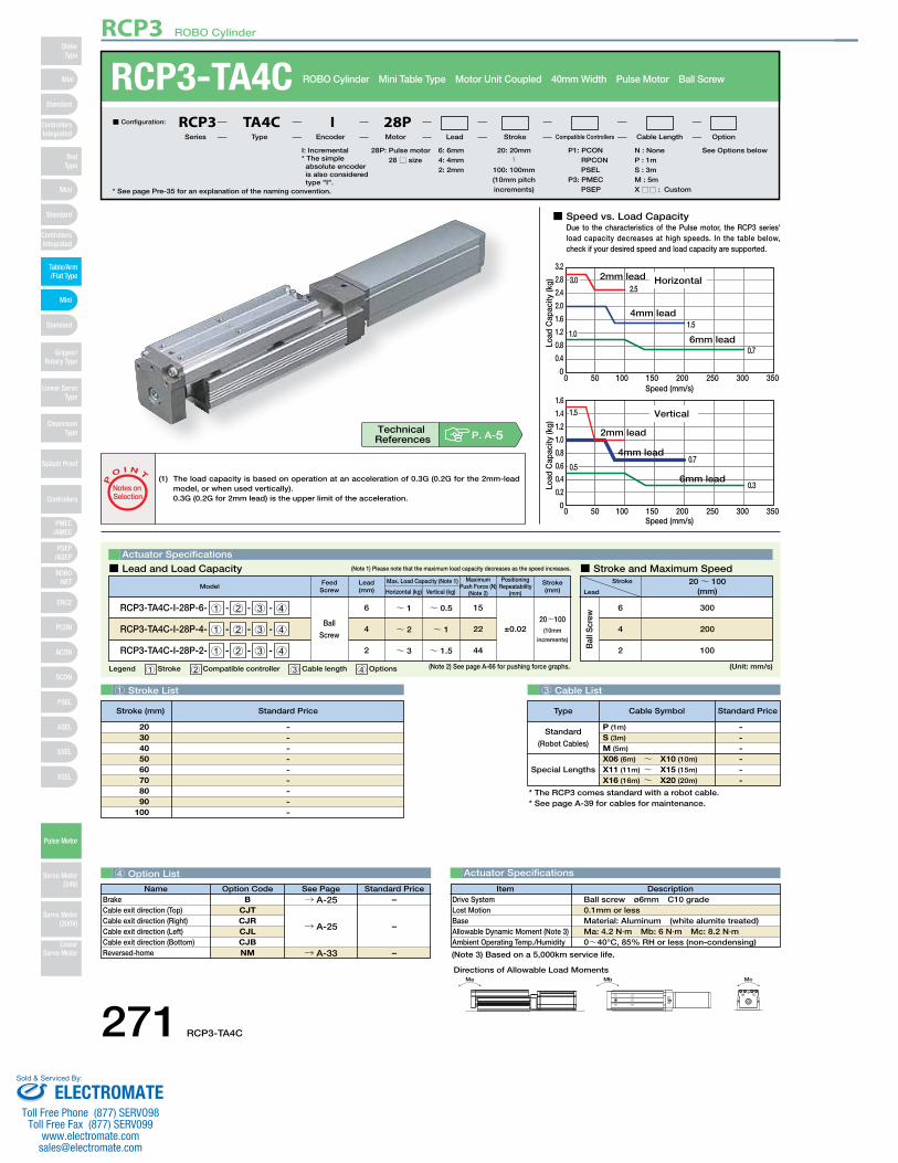
■ Speed vs. Load CapacityDue to the characteristics of the Pulse motor, the RCP3 series'load capacity decreases at high speeds. In the table below, check if your desired speed and load capacity are supported.
0 50 100 150 200 250 300 350Speed (mm/s)
0
0.4
0.8
1.2
1.6
2.0
2.4
2.8
3.2
Horizontal2mm lead
4mm lead
6mm lead
2.5
1.51.01.0
0.7
3.03.0
Load
Cap
acity
(kg)
Speed (mm/s)0 50 100 150 200 250 300 350
0
0.2
0.4
0.6
0.8
1.0
1.2
1.4
1.6
Vertical
2mm lead
4mm lead
6mm lead
1.51.5
0.50.50.7
0.3Load
Cap
acity
(kg)
1 Stroke List 3 Cable List
4 Option List Actuator Specifications
RCP3-TA4C ROBO Cylinder Mini Table Type Motor Unit Coupled 40mm Width Pulse Motor Ball Screw
Legend 1 Stroke 2 Compatible controller 3 Cable length 4 Options
Actuator Specifications
Stroke
Lead
20~ 100(mm)
300
200
100
6
4
2
■ Lead and Load Capacity ■ Stroke and Maximum Speed(Note 1) Please note that the maximum load capacity decreases as the speed increases.
(Unit: mm/s)
* See page Pre-35 for an explanation of the naming convention.
28P: Pulse motor28 □ size
I: Incremental* The simple absolute encoder is also considered type "I".
N : NoneP : 1mS : 3mM : 5mX□□ : Custom
See Options below 6 : 6mm 4 : 4mm 2 : 2mm
■ Configuration: RCP3 TA4C I 28PSeries Type Encoder Motor Lead Stroke Compatible Controllers Cable Length Option
Special Lengths
Type Standard PriceCable Symbol
Standard
(Robot Cables)
P (1m)
S (3m)
M (5m)
X06 (6m) ~ X10 (10m)
X11 (11m) ~ X15 (15m)
X16 (16m) ~ X20 (20m)
------
Name Standard PriceOption Code See PageB
CJTCJRCJLCJBNM
BrakeCable exit direction (Top)Cable exit direction (Right)Cable exit direction (Left)Cable exit direction (Bottom)Reversed-home
DescriptionItemBall screw ø6mm C10 grade 0.1mm or lessMaterial: Aluminum (white alumite treated)Ma: 4.2 N∙m Mb: 6 N∙m Mc: 8.2 N∙m0~40°C, 85% RH or less (non-condensing)
Drive SystemLost MotionBaseAllowable Dynamic Moment (Note 3)Ambient Operating Temp./Humidity
(1) The load capacity is based on operation at an acceleration of 0.3G (0.2G for the 2mm-lead model, or when used vertically).0.3G (0.2G for 2mm lead) is the upper limit of the acceleration.
P
O I N T
Notes on Selection
* The RCP3 comes standard with a robot cable.* See page A-39 for cables for maintenance.
(Note 3) Based on a 5,000km service life.
P1: PCON RPCON PSEL
P3: PMEC PSEP
Pictured above: TA3C
20: 20mm〜
100: 100mm(10mm pitch increments)
P. A-5Technical References
---------
2030405060708090
100
Stroke (mm) Standard Price
–
–
→ A-25
→ A-33
–→ A-25
Ma Mb Mc
Directions of Allowable Load Moments
271 RCP3-TA4C
RCP3 ROBO Cylinder
Mini
Mini
PSEP/ASEP
PMEC/AMEC
ROBONET
ERC2
PCON
ACON
SCON
PSEL
ASEL
SSEL
XSEL
Standard
Mini
Standard
Standard
ControllersIntegrated
ControllersIntegrated
RodType
Table/Arm/Flat Type
Gripper/Rotary Type
Linear ServoType
Cleanroom Type
Splash Proof
Controllers
Pulse Motor
Servo Motor (24V)
Servo Motor (200V)
LinearServo Motor
SliderType
ELECTROMATEToll Free Phone (877) SERVO98
Toll Free Fax (877) SERV099www.electromate.com
Sold & Serviced By:
( )
Secure at least 100
(Left: CJL)
(Top: CJT)
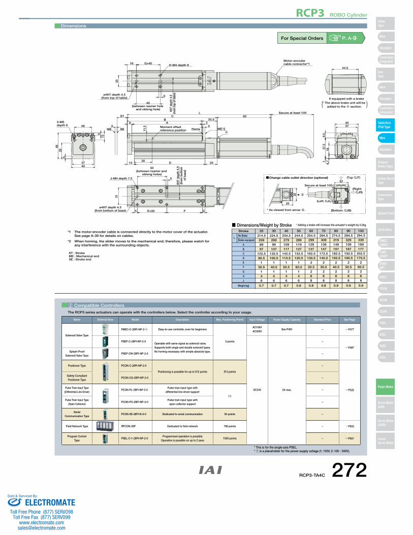
(Bottom: CJB)* As viewed from arrow B.
(Right: CJR)
Change cable outlet direction (optional)
B
25
32
32
3-M5 depth 6 29
ST
8 AB
CL
25.592
Secure at least 100
23
ME*2Home3
4037
513
529
48
20D12
4037
9.5
37.5
16.
718
If equipped with a brakeø4H7 depth 4.5
(from top of table)
40(between reamer hole
and oblong hole)
20
4H7
dept
h 4.
5(fr
om to
p of
tabl
e)
5
16 G×40H-M4 depth 6
44.5
5
4H7
dept
h 4.
5(fr
om b
otto
m o
f bas
e)
5
50(between reamer and
oblong holes)J-M4 depth 7.5
31
ø4H7 depth 4.5(from bottom of base) 5 E×50 F
Motor-encodercable connector*1
SEME
ST : Stroke
* The above brake unit will be added to the A section.
A
Moment offsetreference position11
.5
30
ME : Mechanical endSE : Stroke end
*1 The motor-encoder cable is connected directly to the motor cover of the actuator.See page A-39 for details on cables.
*2 When homing, the slider moves to the mechanical end; therefore, please watch for any interference with the surrounding objects.
Dimensions
■ Dimensions/Weight by StrokeStroke
LNo Brake
Brake-equipped
A
B
C
D
E
F
G
H
J
Weight (kg)
214.52598997
122.590.5
130.5
146
0.7
224.526999107
132.5100.5
140.5
146
0.7
234.5279109117
142.5110.5
150.5
146
0.7
244.5289119127
152.5120.5
160.5
146
0.8
254.5299129137
162.5130.5
220.5
268
0.8
264.5309139147
172.5140.5
230.5
268
0.8
274.5319149157
182.5150.5
240.5
268
0.9
284.5329159167
192.5160.5
250.5
268
0.9
294.5339169177
202.5170.5
260.5
268
0.9
20 30 40 50 60 70 80 90 100
* Adding a brake will increase the actuator's weight by 0.2kg.
For Special Orders P. A-9
2 Compatible Controllers
The RCP3 series actuators can operate with the controllers below. Select the controller according to your usage.
Name External View Model Description Max. Positioning Points Input Voltage Power Supply Capacity Standard Price See Page
Solenoid Valve Type
PMEC-C-28PI-NP-2-1 Easy-to-use controller, even for beginners
3 points
AC100VAC200V
See P481 – → P477
PSEP-C-28PI-NP-2-0Operable with same signal as solenoid valve.Supports both single and double solenoid types.No homing necessary with simple absolute type.
DC24V 2A max.
–
→ P487Splash-Proof
Solenoid Valve TypePSEP-CW-28PI-NP-2-0 –
Positioner Type PCON-C-28PI-NP-2-0
Positioning is possible for up to 512 points 512 points
–
→ P525
Safety-Compliant Positioner Type
PCON-CG-28PI-NP-2-0 –
Pulse Train Input Type(Differential Line Driver)
PCON-PL-28PI-NP-2-0Pulse train input type with
differential line driver support(−)
–
Pulse Train Input Type(Open Collector)
PCON-PO-28PI-NP-2-0Pulse train input type with
open collector support–
Serial Communication Type
PCON-SE-28PI-N-0-0 Dedicated to serial communication 64 points –
Field Network Type RPCON-28P Dedicated to field network 768 points – → P503
Program Control Type
PSEL-C-1-28PI-NP-2-0Programmed operation is possible
Operation is possible on up to 2 axes1500 points – → P557
* This is for the single-axis PSEL.* 1 is a placeholder for the power supply voltage (1: 100V, 2: 100~240V).
RCP3-TA4C 272
RCP3 ROBO Cylinder
Mini
Mini
PSEP/ASEP
PMEC/AMEC
ROBONET
ERC2
PCON
ACON
SCON
PSEL
ASEL
SSEL
XSEL
Standard
Mini
Standard
Standard
ControllersIntegrated
ControllersIntegrated
SliderType
RodType
Table/Arm/Flat Type
Gripper/Rotary Type
Linear ServoType
Cleanroom Type
Splash Proof
Controllers
Pulse Motor
Servo Motor (24V)
Servo Motor (200V)
LinearServo Motor
ELECTROMATEToll Free Phone (877) SERVO98
Toll Free Fax (877) SERV099www.electromate.com
Sold & Serviced By:
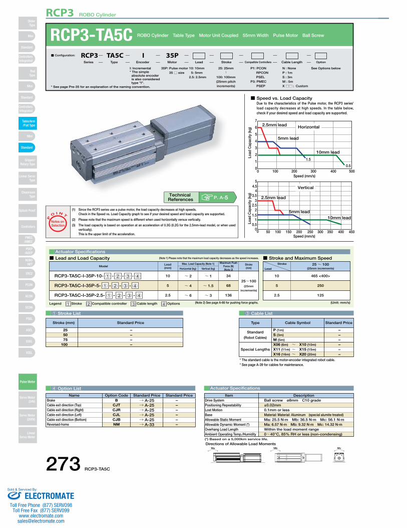
■ Speed vs. Load CapacityDue to the characteristics of the Pulse motor, the RCP3 series'load capacity decreases at high speeds. In the table below, check if your desired speed and load capacity are supported.
0
2
1
3
4
5
6
7
0 100Speed (mm/s)
200 300 400 500
Horizontal
10mm lead
5mm lead
2.5mm lead
1.5
0.5
Load
Cap
acity
(kg)
Speed (mm/s)0 100 15050 200 250 300 350 400 450
00.5
11.5
22.5
33.5
44.5
5
Vertical
2.5mm lead
5mm lead10mm lead
Load
Cap
acity
(kg)
1 Stroke List 3 Cable List
4 Option List Actuator Specifications
RCP3-TA5C ROBO Cylinder Table Type Motor Unit Coupled 55mm Width Pulse Motor Ball Screw
* See page Pre-35 for an explanation of the naming convention.
Legend 1 Stroke 2 Compatible controller 3 Cable length 4 Options (Unit: mm/s)
Actuator Specifications
■ Lead and Load Capacity ■ Stroke and Maximum Speed(Note 1) Please note that the maximum load capacity decreases as the speed increases.
(1) Since the RCP3 series use a pulse motor, the load capacity decreases at high speeds.Check in the Speed vs. Load Capacity graph to see if your desired speed and load capacity are supported.
(2) Please note that the maximum speed is different when used horizontally versus vertically.
(3) The load capacity is based on operation at an acceleration of 0.3G (0.2G for the 2.5mm-lead model, or when used vertically).This is the upper limit of the acceleration.
P
O I N T
Notes on Selection
Stroke
Lead25~ 100
(25mm increments)
465 <400>
250
125
10
5
2.5
35P: Pulse motor35 □ size
I: Incremental* The simple absolute encoder is also considered type "I".
P1: PCON RPCON PSEL
P3: PMEC PSEP
N : NoneP : 1mS : 3mM : 5mX □□ : Custom
See Options below25: 25mm〜
100: 100mm(25mm pitch increments)
10 : 10mm 5 : 5mm 2.5 : 2.5mm
■ Configuration: RCP3 TA5C I 35PSeries Type Encoder Motor Lead Stroke Compatible Controllers Cable Length Option
Lead(mm)
10
5
2.5
Horizontal (kg)
~ 2
~ 4
~ 6
Vertical (kg)
Max. Load Capacity (Note 1) Maximum Push Force (N)(Note 2)
Model
~ 1
~ 1.5
~ 3
34
68
136
Stroke(mm)
RCP3-TA5C-I-35P-10- 1 - 2 - 3 - 4
RCP3-TA5C-I-35P-5- 1 - 2 - 3 - 4
RCP3-TA5C-I-35P-2.5- 1 - 2 - 3 - 4
25~100(25mm
increments)
– – – –
255075
100
Ma Mb Mc
Directions of Allowable Load Moments
DescriptionItemBall screw ø8mm C10 grade±0.02mm0.1mm or lessMaterial: Material: Aluminum (special alumite treated)Ma: 25.5 N∙m Mb: 36.5 N∙m Mc: 56.1 N∙mMa: 6.57 N∙m Mb: 9.32 N∙m Mc: 14.32 N∙mWithin the load moment range0~40°C, 85% RH or less (non-condensing)
Drive SystemPositioning RepeatabilityLost MotionBaseAllowable Static MomentAllowable Dynamic Moment (*)Overhang Load LengthAmbient Operating Temp./Humidity
P. A-5Technical References
* The standard cable is the motor-encoder integrated robot cable.* See page A-39 for cables for maintenance.
Special Lengths
Type Standard PriceCable Symbol
Standard
(Robot Cables)
P (1m)
S (3m)
M (5m)
X06 (6m) ~ X10 (10m)
X11 (11m) ~ X15 (15m)
X16 (16m) ~ X20 (20m)
– – – – – –
(*) Based on a 5,000km service life.
(Note 2) See page A-66 for pushing force graphs.
Name Option Code Standard Price Standard PriceBrake B → A-25 – Cable exit direction (Top) CJT → A-25 – Cable exit direction (Right) CJR → A-25 – Cable exit direction (Left) CJL → A-25 – Cable exit direction (Bottom) CJB → A-25 – Reversed-home NM → A-33 –
Stroke (mm) Standard Price
273 RCP3-TA5C
RCP3 ROBO Cylinder
Mini
Mini
PSEP/ASEP
PMEC/AMEC
ROBONET
ERC2
PCON
ACON
SCON
PSEL
ASEL
SSEL
XSEL
Standard
Mini
Standard
Standard
ControllersIntegrated
ControllersIntegrated
RodType
Table/Arm/Flat Type
Gripper/Rotary Type
Linear ServoType
Cleanroom Type
Splash Proof
Controllers
Pulse Motor
Servo Motor (24V)
Servo Motor (200V)
LinearServo Motor
SliderType
ELECTROMATEToll Free Phone (877) SERVO98
Toll Free Fax (877) SERV099www.electromate.com
Sold & Serviced By:
Secure at least 100
Moment offsetreference position13
.5
49
T
* As viewed from arrow B.
Change cable outlet direction (optional)
(Left: CJL)
(Top: CJT)
(Bottom: CJB)
(Right: CJR)
Secure at least 100
B
25
32
32
Details of the T-slot section
2.7 1.85.5
5.8
3.3
If equipped with a brake
40.5
250
5047
3
3-M6 depth 10 29
146.
5
5534
245
5553
J-M5 depth 10
ø5H7 depth 5
5H7
dept
h 5
6
45
5FEx505
50
ø5H7 depth 5
H-M5 depth 6
5H7
dept
h 56
Gx4021
24
40
ME SEHome ME (*2)
93.5C
18
22.5
14.5 D
L
BA103
st
3
Motor-encoder cableconnector (*1)
* The above brake unit will be added to the A section.( )
A
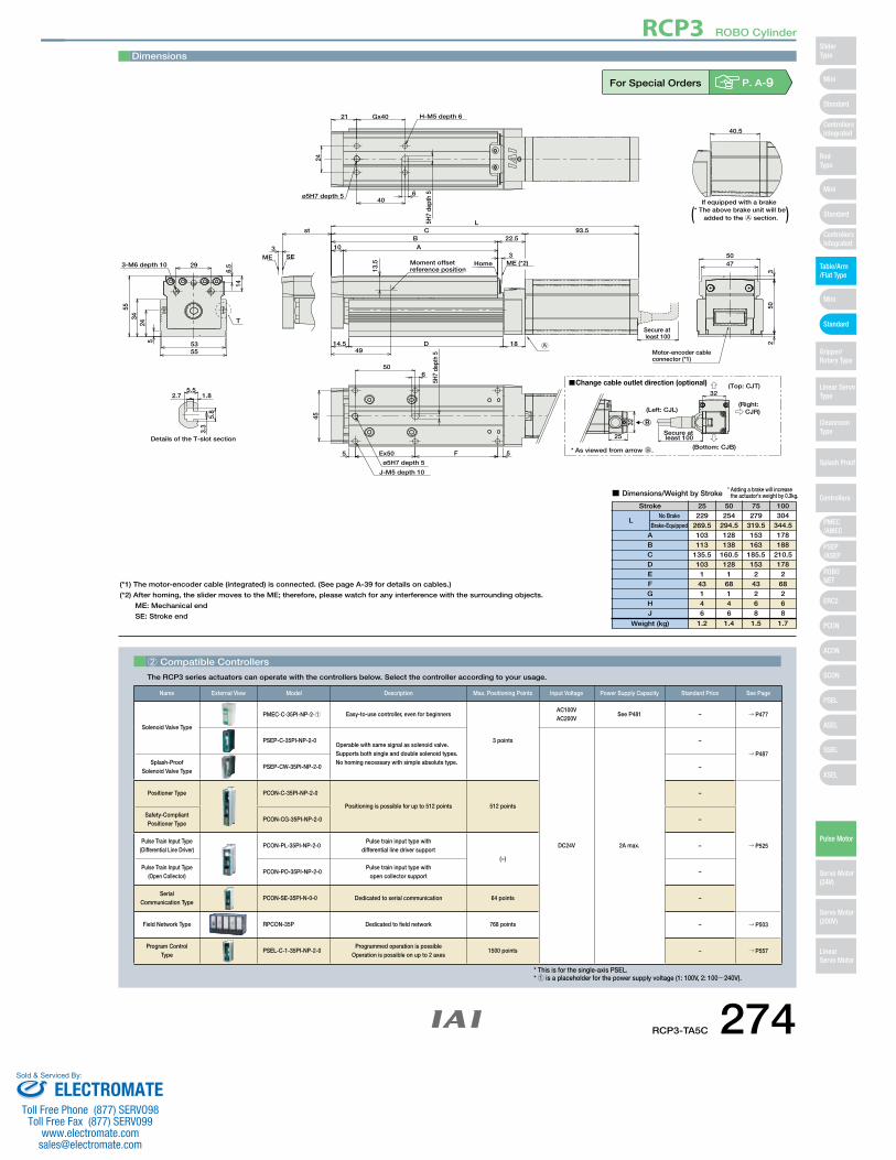
Dimensions
For Special Orders P. A-9
2 Compatible Controllers
The RCP3 series actuators can operate with the controllers below. Select the controller according to your usage.
(*1) The motor-encoder cable (integrated) is connected. (See page A-39 for details on cables.)
(*2) After homing, the slider moves to the ME; therefore, please watch for any interference with the surrounding objects.
ME: Mechanical end
SE: Stroke end
Stroke 25 50 75 100
■ Dimensions/Weight by Stroke
229269.5103113
135.5103
143146
254294.5128138
160.5128
168146
279319.5153163
185.5153
243268
304344.5178188
210.5178
268268
1.2 1.4 1.5 1.7
ABCDEFGHJ
LNo Brake
Brake-Equipped
Weight (kg)
* Adding a brake will increase the actuator's weight by 0.3kg.
Name External View Model Description Max. Positioning Points Input Voltage Power Supply Capacity Standard Price See Page
Solenoid Valve Type
PMEC-C-35PI-NP-2-1 Easy-to-use controller, even for beginners
3 points
AC100VAC200V
See P481 – → P477
PSEP-C-35PI-NP-2-0Operable with same signal as solenoid valve.Supports both single and double solenoid types.No homing necessary with simple absolute type.
DC24V 2A max.
–
→ P487Splash-Proof
Solenoid Valve TypePSEP-CW-35PI-NP-2-0 –
Positioner Type PCON-C-35PI-NP-2-0
Positioning is possible for up to 512 points 512 points
–
→ P525
Safety-Compliant Positioner Type
PCON-CG-35PI-NP-2-0 –
Pulse Train Input Type(Differential Line Driver)
PCON-PL-35PI-NP-2-0Pulse train input type with
differential line driver support(−)
–
Pulse Train Input Type(Open Collector)
PCON-PO-35PI-NP-2-0Pulse train input type with
open collector support–
Serial Communication Type
PCON-SE-35PI-N-0-0 Dedicated to serial communication 64 points –
Field Network Type RPCON-35P Dedicated to field network 768 points – → P503
Program Control Type
PSEL-C-1-35PI-NP-2-0Programmed operation is possible
Operation is possible on up to 2 axes1500 points – → P557
* This is for the single-axis PSEL.* 1 is a placeholder for the power supply voltage (1: 100V, 2: 100~240V).
RCP3-TA5C 274
RCP3 ROBO Cylinder
Mini
Mini
PSEP/ASEP
PMEC/AMEC
ROBONET
ERC2
PCON
ACON
SCON
PSEL
ASEL
SSEL
XSEL
Standard
Mini
Standard
Standard
ControllersIntegrated
ControllersIntegrated
SliderType
RodType
Table/Arm/Flat Type
Gripper/Rotary Type
Linear ServoType
Cleanroom Type
Splash Proof
Controllers
Pulse Motor
Servo Motor (24V)
Servo Motor (200V)
LinearServo Motor
ELECTROMATEToll Free Phone (877) SERVO98
Toll Free Fax (877) SERV099www.electromate.com
Sold & Serviced By:
(*) Based on a 5,000km service life.
* The standard cable is the motor-encoder integrated robot cable.* See page A-39 for cables for maintenance.
Special Lengths
Type Standard PriceCable Symbol
Standard
(Robot Cables)
P (1m)
S (3m)
M (5m)
X06 (6m) ~ X10 (10m)
X11 (11m) ~ X15 (15m)
X16 (16m) ~ X20 (20m)
– – – – – –
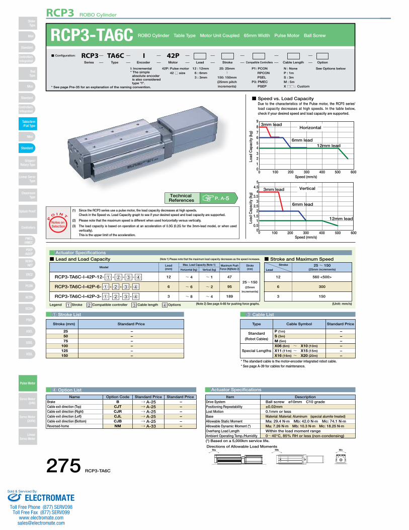
■ Speed vs. Load CapacityDue to the characteristics of the Pulse motor, the RCP3 series'load capacity decreases at high speeds. In the table below, check if your desired speed and load capacity are supported.
0
21
345678
0 100 200 300 400 500 600
9
Speed (mm/s)
Horizontal
6mm lead
3mm lead
12mm lead
Load
Cap
acity
(kg)
0 100 200 300 400 500 6000
0.51
1.52
2.53
3.54
4.55
Speed (mm/s)
Vertical3mm lead
6mm lead
12mm lead
Load
Cap
acity
(kg)
1 Stroke List 3 Cable List
4 Option List Actuator Specifications
RCP3-TA6C ROBO Cylinder Table Type Motor Unit Coupled 65mm Width Pulse Motor Ball Screw
* See page Pre-35 for an explanation of the naming convention.
Legend 1 Stroke 2 Compatible controller 3 Cable length 4 Options (Unit: mm/s)
Actuator Specifications
■ Lead and Load Capacity ■ Stroke and Maximum Speed(Note 1) Please note that the maximum load capacity decreases as the speed increases.
(1) Since the RCP3 series use a pulse motor, the load capacity decreases at high speeds.Check in the Speed vs. Load Capacity graph to see if your desired speed and load capacity are supported.
(2) Please note that the maximum speed is different when used horizontally versus vertically.
(3) The load capacity is based on operation at an acceleration of 0.3G (0.2G for the 3mm-lead model, or when used vertically).This is the upper limit of the acceleration.
P
O I N T
Notes on Selection
Stroke
Lead25~ 150
(25mm increments)
560 <500>
300
150
12
6
3
Lead(mm)
12
6
3
Horizontal (kg)
~ 4
~ 6
~ 8
Vertical (kg)
Max. Load Capacity (Note 1) Maximum Push Force (N)(Note 2)
Model
~ 1
~ 2
~ 4
47
95
189
Stroke(mm)
RCP3-TA6C-I-42P-12- 1 - 2 - 3 - 4
RCP3-TA6C-I-42P-6- 1 - 2 - 3 - 4
RCP3-TA6C-I-42P-3- 1 - 2 - 3 - 4
25~150(25mm
increments)
Ma Mb McDirections of Allowable Load Moments
DescriptionItemBall screw ø10mm C10 grade±0.02mm0.1mm or lessMaterial: Material: Aluminum (special alumite treated)Ma: 29.4 N∙m Mb: 42.0 N∙m Mc: 74.1 N∙mMa: 7.26 N∙m Mb: 10.3 N∙m Mc: 18.25 N∙mWithin the load moment range0~40°C, 85% RH or less (non-condensing)
Drive SystemPositioning RepeatabilityLost MotionBaseAllowable Static MomentAllowable Dynamic Moment (*)Overhang Load LengthAmbient Operating Temp./Humidity
P. A-5Technical References
42P: Pulse motor42 □ size
I: Incremental* The simple absolute encoder is also considered type "I".
P1: PCON RPCON PSEL
P3: PMEC PSEP
N : NoneP : 1mS : 3mM : 5mX □□ : Custom
See Options below25: 25mm〜
150: 150mm(25mm pitch increments)
12 : 12mm6 : 6mm3 : 3mm
■ Configuration: RCP3 TA6C I 42PSeries Type Encoder Motor Lead Stroke Compatible Controllers Cable Length Option
– – – – – –
255075
100125150
(Note 2) See page A-66 for pushing force graphs.
Name Option Code Standard Price Standard PriceBrake B → A-25 – Cable exit direction (Top) CJT → A-25 – Cable exit direction (Right) CJR → A-25 – Cable exit direction (Left) CJL → A-25 – Cable exit direction (Bottom) CJB → A-25 – Reversed-home NM → A-33 –
Stroke (mm) Standard Price
275 RCP3-TA6C
RCP3 ROBO Cylinder
Mini
Mini
PSEP/ASEP
PMEC/AMEC
ROBONET
ERC2
PCON
ACON
SCON
PSEL
ASEL
SSEL
XSEL
Standard
Mini
Standard
Standard
ControllersIntegrated
ControllersIntegrated
RodType
Table/Arm/Flat Type
Gripper/Rotary Type
Linear ServoType
Cleanroom Type
Splash Proof
Controllers
Pulse Motor
Servo Motor (24V)
Servo Motor (200V)
LinearServo Motor
SliderType
ELECTROMATEToll Free Phone (877) SERVO98
Toll Free Fax (877) SERV099www.electromate.com
Sold & Serviced By:
5
Secure at least 100
ME SE3
st
T
* As viewed from arrow B.
Change cable outlet direction (optional)
(Left: CJL)
(Top: CJT)
(Bottom: CJB)
(Right: CJR)
B
Secure at least 10025
32
32
Details of the T-slot section
5.52.7 1.8
5.8
3.3
If equipped with a brake
39.5
1.5
575.
5
60573-M6 depth 13
6439
.529
.55
35
187
6563
J-M5 depth 10ø5H7 depth 5
5H7
dept
h 5
6
FEx505
55
50
ø5H7 depth 5
H-M5 depth 8
5H7
dept
h 56
Gx5027
30
50
Home ME (*2)
97C26.5
19.517.5 D
L
BA13
3
Motor-encoder cableconnector (*1)
* The above brake unit will be added to the A section.
( )
A
Moment offsetreference position15
.5
54.5
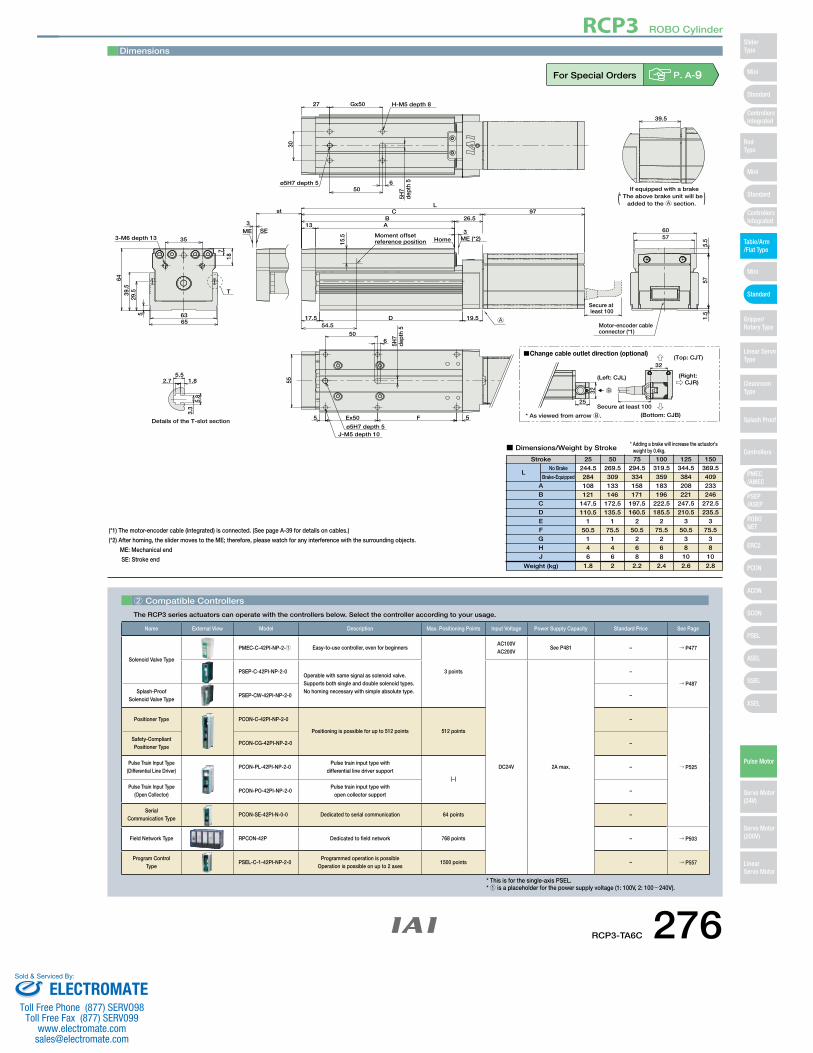
Dimensions
For Special Orders P. A-9
2 Compatible Controllers
The RCP3 series actuators can operate with the controllers below. Select the controller according to your usage.
(*1) The motor-encoder cable (integrated) is connected. (See page A-39 for details on cables.)
(*2) After homing, the slider moves to the ME; therefore, please watch for any interference with the surrounding objects.
ME: Mechanical end
SE: Stroke end
Stroke 25 50 75 100 125 150
■ Dimensions/Weight by Stroke
244.5284108121
147.5110.5
150.5
146
269.5309133146
172.5135.5
175.5
146
294.5334158171
197.5160.5
250.5
268
319.5359183196
222.5185.5
275.5
268
344.5384208221
247.5210.5
350.5
3810
369.5409233246
272.5235.5
375.5
3810
1.8 2 2.2 2.4 2.6 2.8
ABCDEFGHJ
LNo Brake
Brake-Equipped
Weight (kg)
* Adding a brake will increase the actuator's weight by 0.4kg.
Name External View Model Description Max. Positioning Points Input Voltage Power Supply Capacity Standard Price See Page
Solenoid Valve Type
PMEC-C-42PI-NP-2-1 Easy-to-use controller, even for beginners
3 points
AC100VAC200V
See P481 – → P477
PSEP-C-42PI-NP-2-0Operable with same signal as solenoid valve.Supports both single and double solenoid types.No homing necessary with simple absolute type.
DC24V 2A max.
–
→ P487Splash-Proof
Solenoid Valve TypePSEP-CW-42PI-NP-2-0 –
Positioner Type PCON-C-42PI-NP-2-0
Positioning is possible for up to 512 points 512 points
–
→ P525
Safety-Compliant Positioner Type
PCON-CG-42PI-NP-2-0 –
Pulse Train Input Type(Differential Line Driver)
PCON-PL-42PI-NP-2-0Pulse train input type with
differential line driver support(−)
–
Pulse Train Input Type(Open Collector)
PCON-PO-42PI-NP-2-0Pulse train input type with
open collector support–
Serial Communication Type
PCON-SE-42PI-N-0-0 Dedicated to serial communication 64 points –
Field Network Type RPCON-42P Dedicated to field network 768 points – → P503
Program Control Type
PSEL-C-1-42PI-NP-2-0Programmed operation is possible
Operation is possible on up to 2 axes1500 points – → P557
* This is for the single-axis PSEL.* 1 is a placeholder for the power supply voltage (1: 100V, 2: 100~240V).
RCP3-TA6C 276
RCP3 ROBO Cylinder
Mini
Mini
PSEP/ASEP
PMEC/AMEC
ROBONET
ERC2
PCON
ACON
SCON
PSEL
ASEL
SSEL
XSEL
Standard
Mini
Standard
Standard
ControllersIntegrated
ControllersIntegrated
SliderType
RodType
Table/Arm/Flat Type
Gripper/Rotary Type
Linear ServoType
Cleanroom Type
Splash Proof
Controllers
Pulse Motor
Servo Motor (24V)
Servo Motor (200V)
LinearServo Motor
ELECTROMATEToll Free Phone (877) SERVO98
Toll Free Fax (877) SERV099www.electromate.com
Sold & Serviced By:
(*) Based on a 5,000km service life.
* The standard cable is the motor-encoder integrated robot cable.* See page A-39 for cables for maintenance.
Special Lengths
Type Standard PriceCable Symbol
Standard
(Robot Cables)
P (1m)
S (3m)
M (5m)
X06 (6m) ~ X10 (10m)
X11 (11m) ~ X15 (15m)
X16 (16m) ~ X20 (20m)
– – – – – –
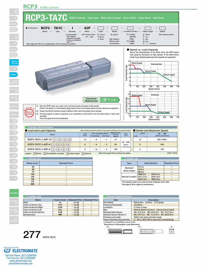
■ Speed vs. Load CapacityDue to the characteristics of the Pulse motor, the RCP3 series'load capacity decreases at high speeds. In the table below, check if your desired speed and load capacity are supported.
0
2
4
6
10
8
12
0 100 200 300 400 500 600 700Speed (mm/s)
Horizontal3mm lead
12mm lead
6mm lead
Load
Cap
acity
(kg)
0 100 200 300 400 500 600 7000
0.51
1.52
2.53
3.54
4.55
Speed (mm/s)
Vertical3mm lead
6mm lead
12mm leadLoad
Cap
acity
(kg)
1 Stroke List 3 Cable List
4 Option List Actuator Specifications
RCP3-TA7C ROBO Cylinder Table Type Motor Unit Coupled 75mm Width Pulse Motor Ball Screw
* See page Pre-35 for an explanation of the naming convention.
Legend 1 Stroke 2 Compatible controller 3 Cable length 4 Options (Unit: mm/s)
Actuator Specifications
■ Lead and Load Capacity ■ Stroke and Maximum Speed(Note 1) Please note that the maximum load capacity decreases as the speed increases.
(1) Since the RCP3 series use a pulse motor, the load capacity decreases at high speeds.Check in the Speed vs. Load Capacity graph below to see if your desired speed and load capacity are supported.
(2) Please note that the maximum speed is different when used horizontally versus vertically.
(3) The load capacity is based on operation at an acceleration of 0.3G (0.2G for the 3mm-lead model, or when used vertically).This is the upper limit of the acceleration.
P
O I N T
Notes on Selection
Stroke
Lead25~ 200
(25mm increments)
600 <580>
300
150
12
6
3
Lead(mm)
12
6
3
Horizontal (kg)
~ 6
~ 8
~ 10
Vertical (kg)
Max. Load Capacity (Note 1) Maximum Push Force (N)(Note 2)
Model
~ 1
~ 2
~ 4
47
95
189
Stroke(mm)
RCP3-TA7C-I-42P-12- 1 - 2 - 3 - 4
RCP3-TA7C-I-42P-6- 1 - 2 - 3 - 4
RCP3-TA7C-I-42P-3- 1 - 2 - 3 - 4
25~200(25mm
increments)
Ma Mb Mc
Directions of Allowable Load Moments
DescriptionItemBall screw ø10mm C10 grade±0.02mm0.1mm or lessMaterial: Material: Aluminum (special alumite treated)Ma: 42.6 N∙m Mb: 60.8 N∙m Mc: 123.2 N∙mMa: 9.91 N∙m Mb: 14.13 N∙m Mc: 28.65 N∙mWithin the load moment range0~40°C, 85% RH or less (non-condensing)
Drive SystemPositioning RepeatabilityLost MotionBaseAllowable Static MomentAllowable Dynamic Moment (*)Overhang Load LengthAmbient Operating Temp./Humidity
42P: Pulse motor42 □ size
I: Incremental* The simple absolute encoder is also considered type "I".
P1: PCON RPCON PSEL
P3: PMEC PSEP
N : None
P : 1mS : 3mM : 5mX □□ : Custom
See Options below25: 25mm〜
200: 200mm(25mm pitch increments)
12 : 12mm 6 : 6mm 3 : 3mm
■ Configuration: RCP3 TA7C I 42PSeries Type Encoder Motor Lead Stroke Compatible Controllers Cable Length Option
P. A-5Technical References
– – – – – – – –
255075
100125150175200
(Note 2) See page A-66 for pushing force graphs.
Name Option Code Standard Price Standard PriceBrake B → A-25 – Cable exit direction (Top) CJT → A-25 – Cable exit direction (Right) CJR → A-25 – Cable exit direction (Left) CJL → A-25 – Cable exit direction (Bottom) CJB → A-25 – Reversed-home NM → A-33 –
Stroke (mm) Standard Price
277 RCP3-TA7C
RCP3 ROBO Cylinder
Mini
Mini
PSEP/ASEP
PMEC/AMEC
ROBONET
ERC2
PCON
ACON
SCON
PSEL
ASEL
SSEL
XSEL
Standard
Mini
Standard
Standard
ControllersIntegrated
ControllersIntegrated
RodType
Table/Arm/Flat Type
Gripper/Rotary Type
Linear ServoType
Cleanroom Type
Splash Proof
Controllers
Pulse Motor
Servo Motor (24V)
Servo Motor (200V)
LinearServo Motor
SliderType
ELECTROMATEToll Free Phone (877) SERVO98
Toll Free Fax (877) SERV099www.electromate.com
Sold & Serviced By:
5
ME SE3
st
T
Moment offsetreference position17
.5
61.5
* As viewed from arrow B.
Change cable outlet direction (optional)
(Left: CJL)
(Top: CJT)
(Bottom: CJB)
(Right: CJR)
B
Secure at least 10025
32
32
Secure at least 100
3-M8 depth 1521
.56.
5
44
6639
.529
.55
7573
5.52.7 1.8
5.8
3.3
Details of the T-slot section
J-M6 depth 12ø6H7 depth 6
FEx505
64
7
6H7
dept
h 6
50
If equipped with a brake
39.5
H-M6 depth 10
ø6H7 depth 6
6H7
dept
h 67
Gx5030
36
50
571.
57.
5
7471Home ME (*2)
C 9716.5
19.519.5 D
L
BA15
3
Motor-encoder cableconnector (*1)
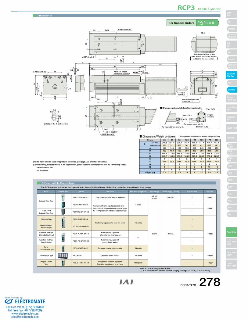
* The above brake unit will be added to the A section.( )
A
Dimensions
For Special Orders P. A-9
2 Compatible Controllers
The RCP3 series actuators can operate with the controllers below. Select the controller according to your usage.
(*1) The motor-encoder cable (integrated) is connected. (See page A-39 for details on cables.)
(*2) After homing, the slider moves to the ME; therefore, please watch for any interference with the surrounding objects.
ME: Mechanical end
SE: Stroke end
Stroke 25 50 75 100 125 150 175 200
■ Dimensions/Weight by Stroke
246.5286118133
149.5110.5
150.5
146
271.5311143158
174.5135.5
175.5
146
296.5336168183
199.5160.5
250.5
268
321.5361193208
224.5185.5
275.5
268
346.5386218233
249.5210.5
350.5
3810
371.5411243258
274.5235.5
375.5
3810
396.5436268283
299.5260.5
450.5
41012
421.5461293308
324.5285.5
475.5
41012
2.1 2.3 2.5 2.8 3 3.2 3.4 3.6
ABCDEFGHJ
LNo Brake
Brake-Equipped
Weight (kg)
* Adding a brake will increase the actuator's weight by 0.4kg.
Name External View Model Description Max. Positioning Points Input Voltage Power Supply Capacity Standard Price See Page
Solenoid Valve Type
PMEC-C-42PI-NP-2-1 Easy-to-use controller, even for beginners
3 points
AC100VAC200V
See P481 – → P477
PSEP-C-42PI-NP-2-0Operable with same signal as solenoid valve.Supports both single and double solenoid types.No homing necessary with simple absolute type.
DC24V 2A max.
–
→ P487Splash-Proof
Solenoid Valve TypePSEP-CW-42PI-NP-2-0 –
Positioner Type PCON-C-42PI-NP-2-0
Positioning is possible for up to 512 points 512 points
–
→ P525
Safety-Compliant Positioner Type
PCON-CG-42PI-NP-2-0 –
Pulse Train Input Type(Differential Line Driver)
PCON-PL-42PI-NP-2-0Pulse train input type with
differential line driver support(−)
–
Pulse Train Input Type(Open Collector)
PCON-PO-42PI-NP-2-0Pulse train input type with
open collector support–
Serial Communication Type
PCON-SE-42PI-N-0-0 Dedicated to serial communication 64 points –
Field Network Type RPCON-42P Dedicated to field network 768 points – → P503
Program Control Type
PSEL-C-1-42PI-NP-2-0Programmed operation is possible
Operation is possible on up to 2 axes1500 points – → P557
* This is for the single-axis PSEL.* 1 is a placeholder for the power supply voltage (1: 100V, 2: 100~240V).
RCP3-TA7C 278
RCP3 ROBO Cylinder
Mini
Mini
PSEP/ASEP
PMEC/AMEC
ROBONET
ERC2
PCON
ACON
SCON
PSEL
ASEL
SSEL
XSEL
Standard
Mini
Standard
Standard
ControllersIntegrated
ControllersIntegrated
SliderType
RodType
Table/Arm/Flat Type
Gripper/Rotary Type
Linear ServoType
Cleanroom Type
Splash Proof
Controllers
Pulse Motor
Servo Motor (24V)
Servo Motor (200V)
LinearServo Motor
ELECTROMATEToll Free Phone (877) SERVO98
Toll Free Fax (877) SERV099www.electromate.com
Sold & Serviced By:
Bal
l Scr
ewLead(mm)
Feed Screw Horizontal (kg) Vertical (kg)
Max. Load Capacity (Note 1) Positioning Repeatability
(mm)
Maximum Push Force (N)
(Note 2)Model
Stroke(mm)
RCP3-TA3R-I-20P-6- 1 - 2 - 3 - 4
RCP3-TA3R-I-20P-4- 1 - 2 - 3 - 4
RCP3-TA3R-I-20P-2- 1 - 2 - 3 - 4
Ball
Screw
~ 0.76
~ 1.44
~ 22
~ 0.3
~ 0.6
~ 1
9
14
28
20~100(10mm
increments)
±0.02
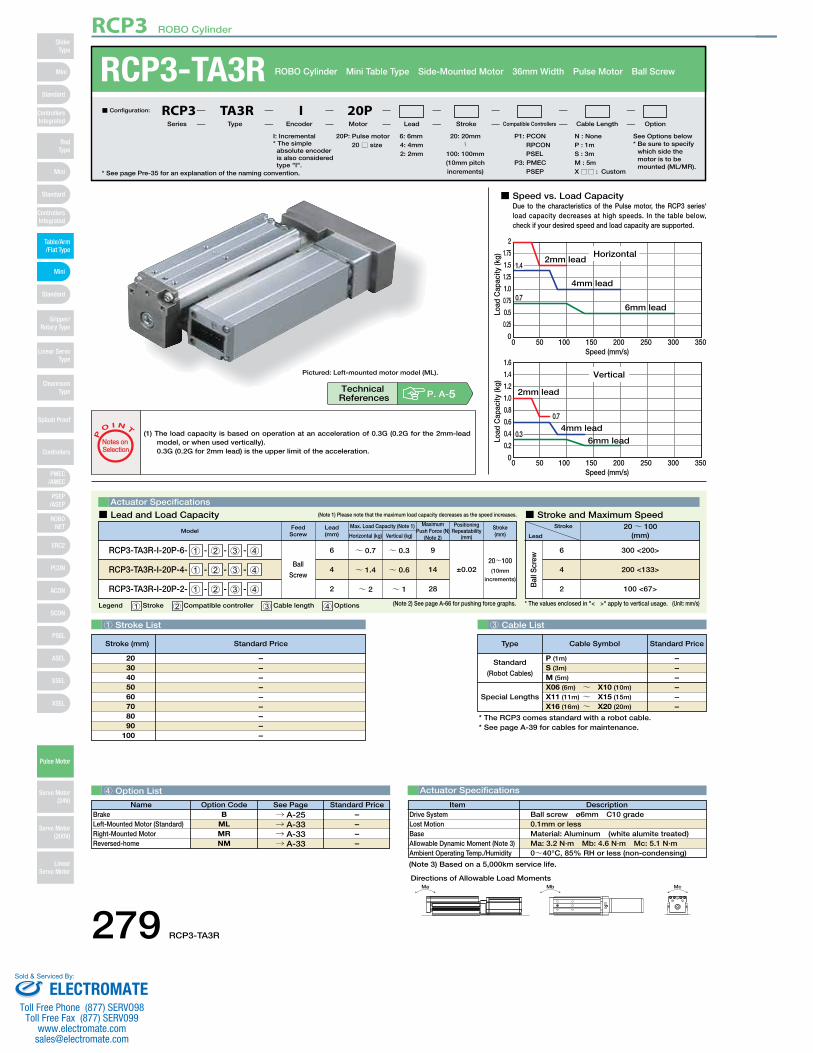
■ Speed vs. Load CapacityDue to the characteristics of the Pulse motor, the RCP3 series'load capacity decreases at high speeds. In the table below, check if your desired speed and load capacity are supported.
0 50 100 150 200 250 300 350Speed (mm/s)
0
0.25
0.5
0.75
1.0
1.25
1.5
1.75
2
Horizontal2mm lead
4mm lead
6mm lead
1.41.4
0.7
Load
Cap
acity
(kg)
0 50 100 150 200 250 300 350Speed (mm/s)
0
0.2
0.4
0.6
0.8
1.0
1.2
1.4
1.6
Vertical
2mm lead
4mm lead
6mm lead0.30.3
0.7
Load
Cap
acity
(kg)
1 Stroke List 3 Cable List
4 Option List Actuator Specifications
RCP3-TA3R ROBO Cylinder Mini Table Type Side-Mounted Motor 36mm Width Pulse Motor Ball Screw
Legend 1 Stroke 2 Compatible controller 3 Cable length 4 Options
Actuator Specifications
Stroke
Lead
20~ 100(mm)
300 <200>
200 <133>
100 <67>
6
4
2
■ Lead and Load Capacity ■ Stroke and Maximum Speed(Note 1) Please note that the maximum load capacity decreases as the speed increases.
(Unit: mm/s)
* See page Pre-35 for an explanation of the naming convention.
20P: Pulse motor20 □ size
I: Incremental* The simple absolute encoder is also considered type "I".
P1: PCON RPCON PSEL
P3: PMEC PSEP
N : NoneP : 1mS : 3mM : 5mX □□ : Custom
See Options below* Be sure to specify
which side the motor is to be mounted (ML/MR).
6: 6mm4: 4mm2: 2mm
■ Configuration: RCP3 TA3R I 20PSeries Type Encoder Motor Lead Stroke Compatible Controllers Cable Length Option
* The RCP3 comes standard with a robot cable.* See page A-39 for cables for maintenance.
Special Lengths
Type Standard PriceCable Symbol
Standard
(Robot Cables)
P (1m)
S (3m)
M (5m)
X06 (6m) ~ X10 (10m)
X11 (11m) ~ X15 (15m)
X16 (16m) ~ X20 (20m)
––––––
–––––––––
2030405060708090
100
DescriptionItemBall screw ø6mm C10 grade 0.1mm or lessMaterial: Aluminum (white alumite treated)Ma: 3.2 N∙m Mb: 4.6 N∙m Mc: 5.1 N∙m0~40°C, 85% RH or less (non-condensing)
Drive SystemLost MotionBaseAllowable Dynamic Moment (Note 3)Ambient Operating Temp./Humidity
(1) The load capacity is based on operation at an acceleration of 0.3G (0.2G for the 2mm-lead model, or when used vertically).0.3G (0.2G for 2mm lead) is the upper limit of the acceleration.
P
O I N T
Notes on Selection
* The values enclosed in "< >" apply to vertical usage.
Name Standard PriceOption Code See PageB
MLMRNM
→ A-25→ A-33→ A-33→ A-33
BrakeLeft-Mounted Motor (Standard)Right-Mounted MotorReversed-home
––––
(Note 3) Based on a 5,000km service life.
(Note 2) See page A-66 for pushing force graphs.
Pictured: Left-mounted motor model (ML).
20: 20mm〜
100: 100mm(10mm pitch increments)
P. A-5Technical References
Stroke (mm) Standard Price
Ma Mb Mc
Directions of Allowable Load Moments
279 RCP3-TA3R
RCP3 ROBO Cylinder
Mini
Mini
PSEP/ASEP
PMEC/AMEC
ROBONET
ERC2
PCON
ACON
SCON
PSEL
ASEL
SSEL
XSEL
Standard
Mini
Standard
Standard
ControllersIntegrated
ControllersIntegrated
RodType
Table/Arm/Flat Type
Gripper/Rotary Type
Linear ServoType
Cleanroom Type
Splash Proof
Controllers
Pulse Motor
Servo Motor (24V)
Servo Motor (200V)
LinearServo Motor
SliderType
ELECTROMATEToll Free Phone (877) SERVO98
Toll Free Fax (877) SERV099www.electromate.com
Sold & Serviced By:
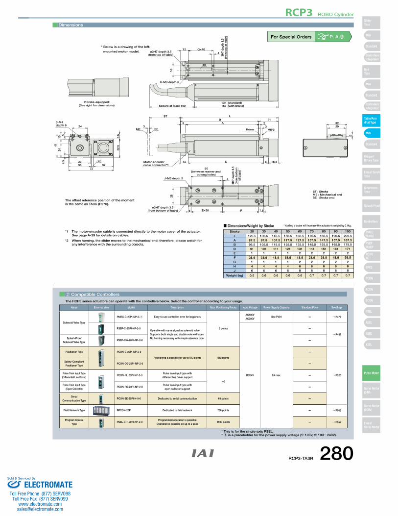
If brake-equipped:(See right for dimensions)
3-M4 depth 6 24
4124
10
32.5
8.55
4.5 33
3672
324
ME SE3
ST
8 AB 31
L
23
ME*2Home
15.58D12
J-M3 depth 5 4
50(between reamer and
oblong holes)
3H7
dept
h 3.
5(fr
om b
otto
m
of b
ase)
7.5FE×505ø3H7 depth 3.5
(from bottom of base)
28
Secure at least 100134 (standard)157 (with brake)
H-M3 depth 6
16
ø3H7 depth 3.5(from top of table)
12 G×404
40
3H7
dept
h 3.
5(fr
om to
p of
tabl
e)
3229
5
Motor-encodercable connector*1
ST : StrokeME : Mechanical endSE : Stroke end
Dimensions
■ Dimensions/Weight by StrokeStroke
LABDEFGHJ
Weight (kg)
126.587.595.5911
28.5146
0.5
136.597.5105.5101
138.5
146
0.6
146.5107.5115.5111
148.5
146
0.6
156.5117.5125.5121
158.5
146
0.6
166.5127.5135.5131
218.5
268
0.6
176.5137.5145.5141
228.5
268
0.7
186.5147.5155.5151
238.5
268
0.7
196.5157.5165.5161
248.5
268
0.7
206.5167.5175.5171
258.5
268
0.7
20 30 40 50 60 70 80 90 100
* Adding a brake will increase the actuator's weight by 0.1kg.
*1 The motor-encoder cable is connected directly to the motor cover of the actuator. See page A-39 for details on cables.
*2 When homing, the slider moves to the mechanical end; therefore, please watch for any interference with the surrounding objects.
The offset reference position of the momentis the same as TA3C (P270).
For Special Orders P. A-9
2 Compatible Controllers
The RCP3 series actuators can operate with the controllers below. Select the controller according to your usage.
Name External View Model Description Max. Positioning Points Input Voltage Power Supply Capacity Standard Price See Page
Solenoid Valve Type
PMEC-C-20PI-NP-2-1 Easy-to-use controller, even for beginners
3 points
AC100VAC200V
See P481 – → P477
PSEP-C-20PI-NP-2-0Operable with same signal as solenoid valve.Supports both single and double solenoid types.No homing necessary with simple absolute type.
DC24V 2A max.
–→ P487
Splash-Proof Solenoid Valve Type
PSEP-CW-20PI-NP-2-0 –
Positioner Type PCON-C-20PI-NP-2-0
Positioning is possible for up to 512 points 512 points
–
→ P525
Safety-Compliant Positioner Type
PCON-CG-20PI-NP-2-0 –
Pulse Train Input Type(Differential Line Driver)
PCON-PL-20PI-NP-2-0Pulse train input type with different line driver support
(–)
–
Pulse Train Input Type(Open Collector)
PCON-PO-20PI-NP-2-0Pulse train input type with
open collector support –
Serial Communication Type
PCON-SE-20PI-N-0-0 Dedicated to serial communication 64 points –
Field Network Type RPCON-20P Dedicated to field network 768 points – → P503
Program Control Type
PSEL-C-1-20PI-NP-2-0Programmed operation is possible
Operation is possible on up to 2 axes1500 points – → P557
* This is for the single-axis PSEL.* 1 is a placeholder for the power supply voltage (1: 100V, 2: 100~240V).
* Below is a drawing of the left-
mounted motor model.
RCP3-TA3R 280
RCP3 ROBO Cylinder
Mini
Mini
PSEP/ASEP
PMEC/AMEC
ROBONET
ERC2
PCON
ACON
SCON
PSEL
ASEL
SSEL
XSEL
Standard
Mini
Standard
Standard
ControllersIntegrated
ControllersIntegrated
SliderType
RodType
Table/Arm/Flat Type
Gripper/Rotary Type
Linear ServoType
Cleanroom Type
Splash Proof
Controllers
Pulse Motor
Servo Motor (24V)
Servo Motor (200V)
LinearServo Motor
ELECTROMATEToll Free Phone (877) SERVO98
Toll Free Fax (877) SERV099www.electromate.com
Sold & Serviced By:
Bal
l Scr
ewLead(mm)
Feed Screw Horizontal (kg) Vertical (kg)
Max. Load Capacity (Note 1) Positioning Repeatability
(mm)
Maximum Push Force (N)
(Note 2)Model
Stroke(mm)
RCP3-TA4R-I-28P-6- 1 - 2 - 3 - 4
RCP3-TA4R-I-28P-4- 1 - 2 - 3 - 4
RCP3-TA4R-I-28P-2- 1 - 2 - 3 - 4
Ball
Screw
~ 16
~ 24
~ 32
~ 0.5
~ 1
~ 1.5
15
22
44
20~100(10mm
increments)
±0.02
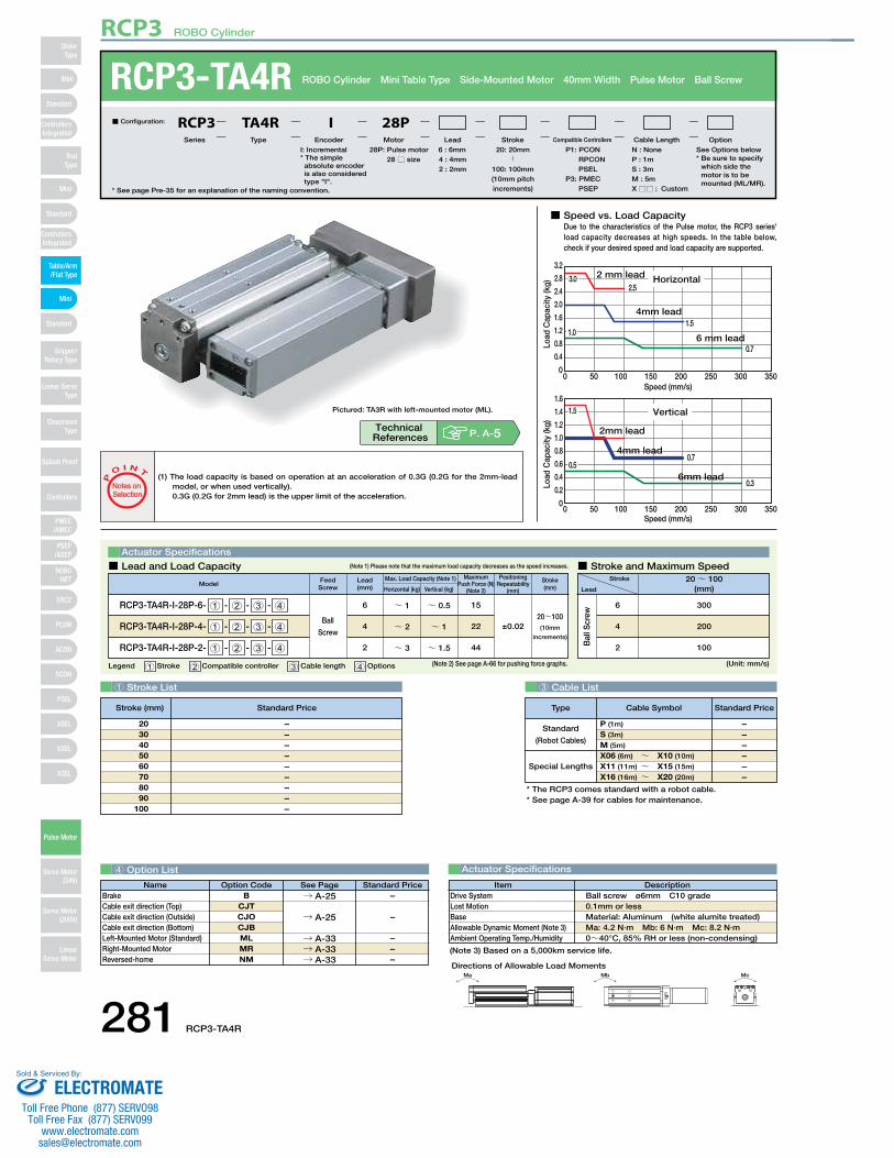
■ Speed vs. Load CapacityDue to the characteristics of the Pulse motor, the RCP3 series'load capacity decreases at high speeds. In the table below, check if your desired speed and load capacity are supported.
0 50 100 150 200 250 300 350Speed (mm/s)
0
0.4
0.8
1.2
1.6
2.0
2.4
2.8
3.2
Horizontal2 mm lead
4mm lead
6 mm lead
2.5
1.51.01.0
0.7
3.03.0
Load
Cap
acity
(kg)
Speed (mm/s)0 50 100 150 200 250 300 350
0
0.2
0.4
0.6
0.8
1.0
1.2
1.4
1.6
Vertical
2mm lead
4mm lead
6mm lead
1.51.5
0.50.50.7
0.3Load
Cap
acity
(kg)
1 Stroke List 3 Cable List
4 Option List Actuator Specifications
RCP3-TA4R ROBO Cylinder Mini Table Type Side-Mounted Motor 40mm Width Pulse Motor Ball Screw
Legend 1 Stroke 2 Compatible controller 3 Cable length 4 Options
Actuator Specifications
Stroke
Lead
20~ 100(mm)
300
200
100
6
4
2
■ Lead and Load Capacity ■ Stroke and Maximum Speed(Note 1) Please note that the maximum load capacity decreases as the speed increases.
(Unit: mm/s)
* See page Pre-35 for an explanation of the naming convention.
28P: Pulse motor 28 □ size
I: Incremental* The simple absolute encoder is also considered type "I".
P1: PCON RPCON PSEL
P3: PMEC PSEP
N : NoneP : 1mS : 3mM : 5mX □□ : Custom
6 : 6mm4 : 4mm2 : 2mm
■ Configuration: RCP3 TA4R I 28PSeries Type Encoder Motor Lead Stroke Compatible Controllers Cable Length Option
* The RCP3 comes standard with a robot cable.* See page A-39 for cables for maintenance.
Special Lengths
Type Standard PriceCable Symbol
Standard
(Robot Cables)
P (1m)
S (3m)
M (5m)
X06 (6m) ~ X10 (10m)
X11 (11m) ~ X15 (15m)
X16 (16m) ~ X20 (20m)
––––––
–––––––––
2030405060708090
100
DescriptionItemBall screw ø6mm C10 grade 0.1mm or lessMaterial: Aluminum (white alumite treated)Ma: 4.2 N∙m Mb: 6 N∙m Mc: 8.2 N∙m0~40°C, 85% RH or less (non-condensing)
Drive SystemLost MotionBaseAllowable Dynamic Moment (Note 3)Ambient Operating Temp./Humidity
(1) The load capacity is based on operation at an acceleration of 0.3G (0.2G for the 2mm-lead model, or when used vertically).0.3G (0.2G for 2mm lead) is the upper limit of the acceleration.
P
O I N T
Notes on Selection
(Note 3) Based on a 5,000km service life.
(Note 2) See page A-66 for pushing force graphs.
Pictured: TA3R with left-mounted motor (ML).
20: 20mm〜
100: 100mm(10mm pitch increments)
P. A-5Technical References
Stroke (mm) Standard Price
Name Standard PriceOption Code See PageB
CJTCJOCJBMLMRNM
BrakeCable exit direction (Top)Cable exit direction (Outside)Cable exit direction (Bottom)Left-Mounted Motor (Standard)Right-Mounted MotorReversed-home
→ A-25
→ A-33→ A-33→ A-33
–
–––
→ A-25 –
See Options below* Be sure to specify
which side themotor is to bemounted (ML/MR).
Ma Mb Mc
Directions of Allowable Load Moments
281 RCP3-TA4R
RCP3 ROBO Cylinder
Mini
Mini
PSEP/ASEP
PMEC/AMEC
ROBONET
ERC2
PCON
ACON
SCON
PSEL
ASEL
SSEL
XSEL
Standard
Mini
Standard
Standard
ControllersIntegrated
ControllersIntegrated
RodType
Table/Arm/Flat Type
Gripper/Rotary Type
Linear ServoType
Cleanroom Type
Splash Proof
Controllers
Pulse Motor
Servo Motor (24V)
Servo Motor (200V)
LinearServo Motor
SliderType
ELECTROMATEToll Free Phone (877) SERVO98
Toll Free Fax (877) SERV099www.electromate.com
Sold & Serviced By:
3-M5 depth 6 29
37
8137.9
3711
3.140
4829
135
5
ME3
SE
ST
8 A 23
B 32L
ME*2Home
19.57D12
J-M4 depth 7.5
31
ø4H7 depth 4.5(from bottom of base) 5 E×50 F 5
4H7
dept
h 4.
5(fr
om b
otto
m
of b
ase)
5
50(between reamer and
oblong holes)
126.2 (standard)158.2 (with brake)
H-M4 depth 6
20
ø4H7 depth 4.5(from top of table)
165
G×40
40
4H7
dept
h 4.
5(fr
om to
p of
tabl
e)
4037
5
If brake-equipped:(See right for dimensions) Secure at least 100
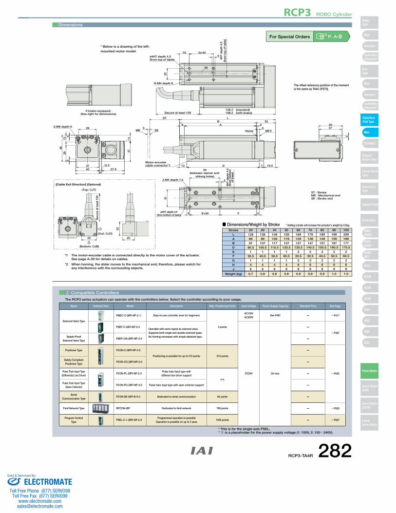
Motor-encodercable connector*1
ST : StrokeME : Mechanical endSE : Stroke end
Sec
ure
at le
ast 1
00
[Cable Exit Direction] (Optional)
32 25
32
(Top: CJT)
(Out: CJO)
(Bottom: CJB)
Dimensions
■ Dimensions/Weight by StrokeStroke
LABDEFGHJ
Weight (kg)
1298997
90.51
30.5146
0.7
13999107
100.51
40.5146
0.8
149109117
110.51
50.5146
0.8
159119127
120.51
60.5146
0.8
169129137
130.52
20.5268
0.9
179139147
140.52
30.5268
0.9
189149157
150.52
40.5268
0.9
199159167
160.52
50.5268
1.0
209169177
170.52
60.5268
1.0
20 30 40 50 60 70 80 90 100
* Adding a brake will increase the actuator's weight by 0.2kg.
The offset reference position of the momentis the same as TA4C (P272).
*1 The motor-encoder cable is connected directly to the motor cover of the actuator.See page A-39 for details on cables.
*2 When homing, the slider moves to the mechanical end; therefore, please watch for any interference with the surrounding objects.
For Special Orders P. A-9
2 Compatible Controllers
The RCP3 series actuators can operate with the controllers below. Select the controller according to your usage.
Name External View Model Description Max. Positioning Points Input Voltage Power Supply Capacity Standard Price See Page
Solenoid Valve Type
PMEC-C-28PI-NP-2-1 Easy-to-use controller, even for beginners
3 points
AC100VAC200V
See P481 – → P477
PSEP-C-28PI-NP-2-0Operable with same signal as solenoid valve.Supports both single and double solenoid types.No homing necessary with simple absolute type.
DC24V 2A max.
–→ P487
Splash-Proof Solenoid Valve Type
PSEP-CW-28PI-NP-2-0 –
Positioner Type PCON-C-28PI-NP-2-0
Positioning is possible for up to 512 points 512 points
–
→ P525
Safety-Compliant Positioner Type
PCON-CG-28PI-NP-2-0 –
Pulse Train Input Type(Differential Line Driver)
PCON-PL-28PI-NP-2-0Pulse train input type with different line driver support
(–)
–
Pulse Train Input Type(Open Collector)
PCON-PO-28PI-NP-2-0 Pulse train input type with open collector support –
Serial Communication Type
PCON-SE-28PI-N-0-0 Dedicated to serial communication 64 points –
Field Network Type RPCON-28P Dedicated to field network 768 points – → P503
Program Control Type
PSEL-C-1-28PI-NP-2-0Programmed operation is possible
Operation is possible on up to 2 axes1500 points – → P557
* This is for the single-axis PSEL.* 1 is a placeholder for the power supply voltage (1: 100V, 2: 100~240V).
* Below is a drawing of the left-
mounted motor model.
RCP3-TA4R 282
RCP3 ROBO Cylinder
Mini
Mini
PSEP/ASEP
PMEC/AMEC
ROBONET
ERC2
PCON
ACON
SCON
PSEL
ASEL
SSEL
XSEL
Standard
Mini
Standard
Standard
ControllersIntegrated
ControllersIntegrated
SliderType
RodType
Table/Arm/Flat Type
Gripper/Rotary Type
Linear ServoType
Cleanroom Type
Splash Proof
Controllers
Pulse Motor
Servo Motor (24V)
Servo Motor (200V)
LinearServo Motor
ELECTROMATEToll Free Phone (877) SERVO98
Toll Free Fax (877) SERV099www.electromate.com
Sold & Serviced By:

RCP3-TA5R ROBO Cylinder Table Type Side-Mounted Motor 55mm Width Pulse Motor Ball Screw
Ma Mb Mc
Directions of Allowable Load Moments
5,000 km service life
■ Speed vs. Load CapacityDue to the characteristics of the Pulse motor, the RCP3 series' load capacity decreases at high speeds. In the table below, check if your desired speed and load capacity are supported.
0
2
1
3
4
5
6
7
0 100Speed (mm/s)
200 300 400 500
Horizontal
10mm lead
5mm lead
2.5mm lead
1.5
0.5
Load
Cap
acity
(kg)
Speed (mm/s)0 100 15050 200 250 300 350 400 450
00.5
11.5
22.5
33.5
44.5
5
Vertical
2.5mm lead
5mm lead10mm lead
Load
Cap
acity
(kg)
1 Stroke List 3 Cable List
4 Option List Actuator Specifications
DescriptionItemBall screw ø8mm C10 grade±0.02mm0.1mm or lessMaterial: Material: Aluminum (special alumite treated)Ma: 25.5 N∙m Mb: 36.5 N∙m Mc: 56.1 N∙mMa: 6.57 N∙m Mb: 9.32 N∙m Mc: 14.32 N∙mWithin the load moment range0~40°C, 85% RH or less (non-condensing)
Drive SystemPositioning RepeatabilityLost MotionBaseAllowable Static Load MomentAllowable Dynamic Load MomentOverhang Load LengthAmbient Operating Temp./Humidity
* See page Pre-35 for an explanation of the naming convention.
35P: Pulse motor 35 □ size
P1: PCONRPCONPSEL
P3: PMECPSEP
N : NoneP : 1mS : 3mM : 5mX □□ : Custom
See Options below* Be sure to specify
which side the motor is to be mounted (ML/MR).
25: 25mm〜
100: 100mm(25mm pitch increments)
10: 10mm5: 5mm
2.5: 2.5mm
■ Configuration: RCP3 TA5R I 35PSeries Type Encoder Motor Lead Stroke Compatible Controllers Cable Length Option
Legend 1 Stroke 2 Compatible controller 3 Cable length 4 Options (Unit: mm/s)* The values enclosed in "< >" apply to vertical usage.
Actuator Specifications
■ Lead and Load Capacity ■ Stroke and Maximum Speed
(1) Since the RCP3 series use a pulse motor, the load capacity decreases at high speeds.Check in the Speed vs. Load Capacity graph to see if your desired speed and load capacity are supported.
(2) Please note that the maximum speed is different when used horizontally versus vertically.
(3) The load capacity is based on operation at an acceleration of 0.3G (0.2G for the 2.5mm-lead model, or when used vertically). This is the upper limit of the acceleration.
P
O I N T
Notes on Selection
––––
255075
100
Lead(mm)
10
5
2.5
Horizontal (kg)
~ 2
~ 4
~ 6
Vertical (kg)
Max. Load Capacity Maximum Push Force (N)Model
~ 1
~ 1.5
~ 3
34
68
136
Stroke(mm)
RCP3-TA5R-I-35P-10- 1 - 2 - 3 - 4
RCP3-TA5R-I-35P-5- 1 - 2 - 3 - 4
RCP3-TA5R-I-35P-2.5- 1 - 2 - 3 - 4
25~100(25mm
increments)
Stroke
Lead25~ 100
(25mm increments)
465 <400>
250
125
10
5
2.5
Special Lengths
Type Standard PriceCable Symbol
Standard
(Robot Cables)
P (1m)
S (3m)
M (5m)
X06 (6m) ~ X10 (10m)
X11 (11m) ~ X15 (15m)
X16 (16m) ~ X20 (20m)
––––––
P. A-5Technical References
I: Incremental* The simple absolute encoder is also considered type "I".
* The standard cable is the motor-encoder integrated robot cable.* See page A-39 for cables for maintenance.
Stroke (mm) Standard Price
Name Standard PriceOption Code See PageB
CJTCJOCJBMLMRNM
BrakeCable exit direction (Top)Cable exit direction (Outside)Cable exit direction (Bottom)Left-Mounted Motor (Standard)Right-Mounted MotorReversed-home
→ A-25
→ A-33→ A-33→ A-33
–
–––
→ A-25 –
283 RCP3-TA5R
RCP3 ROBO Cylinder
Mini
Mini
PSEP/ASEP
PMEC/AMEC
ROBONET
ERC2
PCON
ACON
SCON
PSEL
ASEL
SSEL
XSEL
Standard
Mini
Standard
Standard
ControllersIntegrated
ControllersIntegrated
RodType
Table/Arm/Flat Type
Gripper/Rotary Type
Linear ServoType
Cleanroom Type
Splash Proof
Controllers
Pulse Motor
Servo Motor (24V)
Servo Motor (200V)
LinearServo Motor
SliderType
ELECTROMATEToll Free Phone (877) SERVO98
Toll Free Fax (877) SERV099www.electromate.com
Sold & Serviced By:
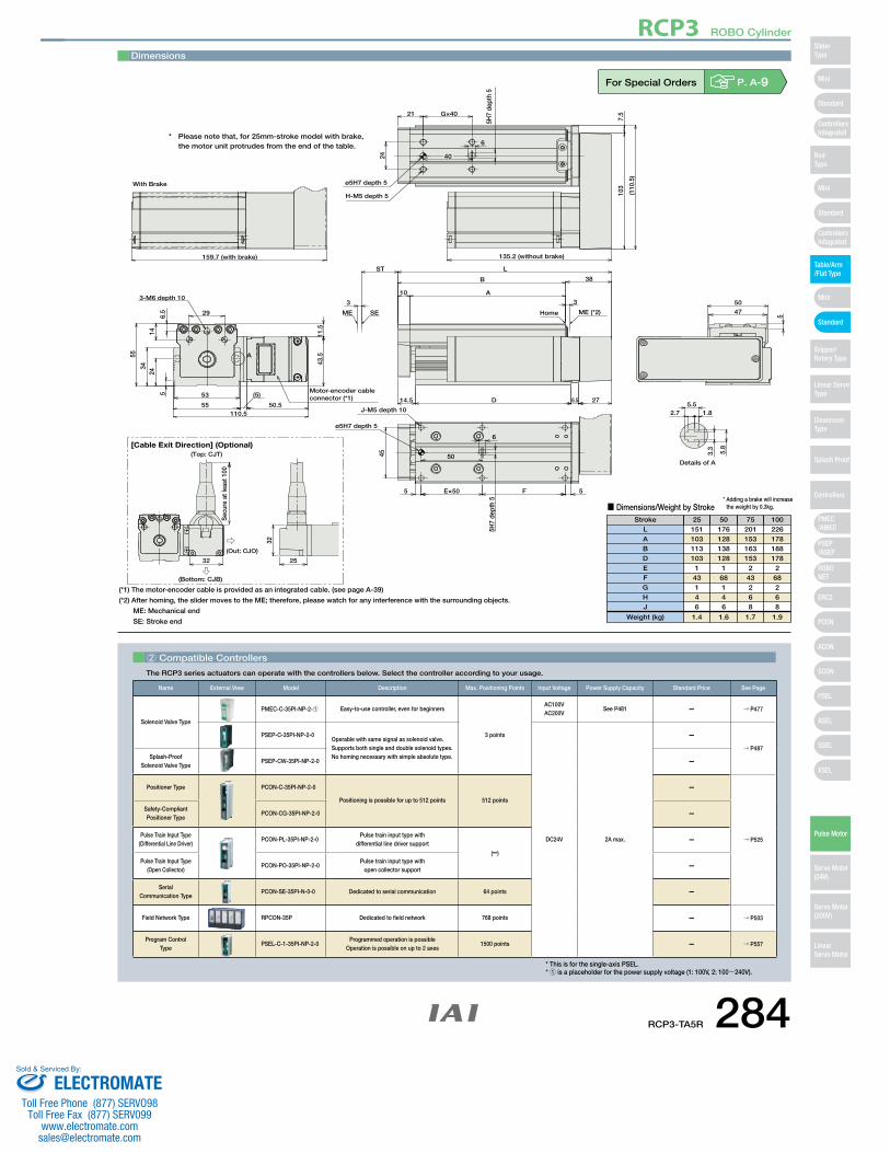
5045
5 E×50 F 5
6
5H7
dept
h 5
J-M5 depth 10
53
55
5
2434
55
(5)
50.5110.5
296.5
14
3-M6 depth 10
43.5
11.5
3.3
5.8
1.85.5
2.7
159.7 (with brake)
With Brake
ø5H7 depth 5
Details of A
Motor-encoder cableconnector (*1)
A
5
50
47ME SE
10
L
38B
A
276.5D14.5
3
ST
3
7.5
103
(110
.5)
6
21 G×40
24
ø5H7 depth 5
H-M5 depth 5
5H7
dept
h 5
135.2 (without brake)
ME (*2)Home
40
(Bottom: CJB)
Sec
ure
at le
ast 1
00
32 25
32
[Cable Exit Direction] (Optional)(Top: CJT)
(Out: CJO)
(*1) The motor-encoder cable is provided as an integrated cable. (see page A-39)
(*2) After homing, the slider moves to the ME; therefore, please watch for any interference with the surrounding objects.
ME: Mechanical end
SE: Stroke end
* Adding a brake will increase the weight by 0.3kg.
Stroke 25 50 75 100
■ Dimensions/Weight by Stroke
151 176 201 226 103 128 153 178 113 138 163 188 103 128 153 178
1 1 2 2 43 68 43 68 1 1 2 2 4 4 6 6 6 6 8 8
1.4 1.6 1.7 1.9
LABDEFGHJ
Weight (kg)
Dimensions
For Special Orders P. A-9
2 Compatible Controllers
The RCP3 series actuators can operate with the controllers below. Select the controller according to your usage.
Name External View Model Description Max. Positioning Points Input Voltage Power Supply Capacity Standard Price See Page
Solenoid Valve Type
PMEC-C-35PI-NP-2-1 Easy-to-use controller, even for beginners
3 points
AC100VAC200V
See P481 – → P477
PSEP-C-35PI-NP-2-0Operable with same signal as solenoid valve.Supports both single and double solenoid types.No homing necessary with simple absolute type.
DC24V 2A max.
–→ P487
Splash-Proof Solenoid Valve Type
PSEP-CW-35PI-NP-2-0 –
Positioner Type PCON-C-35PI-NP-2-0
Positioning is possible for up to 512 points 512 points
–
→ P525
Safety-Compliant Positioner Type
PCON-CG-35PI-NP-2-0 –
Pulse Train Input Type(Differential Line Driver)
PCON-PL-35PI-NP-2-0Pulse train input type with
differential line driver support
(–)
–
Pulse Train Input Type(Open Collector)
PCON-PO-35PI-NP-2-0Pulse train input type with
open collector support –
Serial Communication Type
PCON-SE-35PI-N-0-0 Dedicated to serial communication 64 points –
Field Network Type RPCON-35P Dedicated to field network 768 points – → P503
Program Control Type
PSEL-C-1-35PI-NP-2-0Programmed operation is possible
Operation is possible on up to 2 axes1500 points – → P557
* This is for the single-axis PSEL.* 1 is a placeholder for the power supply voltage (1: 100V, 2: 100~240V).
* Please note that, for 25mm-stroke model with brake, the motor unit protrudes from the end of the table.
RCP3-TA5R 284
RCP3 ROBO Cylinder
Mini
Mini
PSEP/ASEP
PMEC/AMEC
ROBONET
ERC2
PCON
ACON
SCON
PSEL
ASEL
SSEL
XSEL
Standard
Mini
Standard
Standard
ControllersIntegrated
ControllersIntegrated
SliderType
RodType
Table/Arm/Flat Type
Gripper/Rotary Type
Linear ServoType
Cleanroom Type
Splash Proof
Controllers
Pulse Motor
Servo Motor (24V)
Servo Motor (200V)
LinearServo Motor
ELECTROMATEToll Free Phone (877) SERVO98
Toll Free Fax (877) SERV099www.electromate.com
Sold & Serviced By:
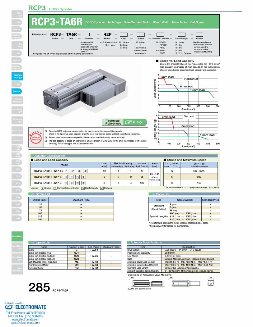
RCP3-TA6R ROBO Cylinder Table Type Side-Mounted Motor 65mm Width Pulse Motor Ball Screw
Special Lengths
Type Standard PriceCable Symbol
Standard
(Robot Cables)
P (1m)
S (3m)
M (5m)
X06 (6m) ~ X10 (10m)
X11 (11m) ~ X15 (15m)
X16 (16m) ~ X20 (20m)
––––––
Ma Mb Mc
Directions of Allowable Load Moments
■ Speed vs. Load CapacityDue to the characteristics of the Pulse motor, the RCP3 series' load capacity decreases at high speeds. In the table below, check if your desired speed and load capacity are supported.
0
21
345678
0 100 200 300 400 500 600
9
Speed (mm/s)
Horizontal
6mm lead
3mm lead
12mm lead
Load
Cap
acity
(kg)
0 100 200 300 400 500 6000
0.51
1.52
2.53
3.54
4.55
Speed (mm/s)
Vertical3mm lead
6mm lead
12mm lead
Load
Cap
acity
(kg)
1 Stroke List 3 Cable List
4 Option List Actuator Specifications
DescriptionItemBall screw ø10mm C10 grade±0.02mm0.1mm or lessMaterial: Material: Aluminum (special alumite treated)Ma: 29.4 N∙m Mb: 42.0 N∙m Mc: 74.1 N∙mMa: 7.26 N∙m Mb: 10.3 N∙m Mc: 18.25 N∙mWithin the load moment range0~40°C, 85% RH or less (non-condensing)
Drive SystemPositioning RepeatabilityLost MotionBaseAllowable Static Load MomentAllowable Dynamic Load MomentOverhang Load LengthAmbient Operating Temp./Humidity
* See page Pre-35 for an explanation of the naming convention.
42P: Pulse motor 42 □ size
P1: PCON RPCON PSEL
P3: PMEC PSEP
N : NoneP : 1mS : 3mM : 5mX □□ : Custom
25: 25mm〜
150: 150mm(25mm pitch increments)
12 : 12mm 6 : 6mm 3 : 3mm
■ Configuration: RCP3 TA6R I 42PSeries Type Encoder Motor Lead Stroke Compatible Controllers Cable Length Option
Legend 1 Stroke 2 Compatible controller 3 Cable length 4 Options (Unit: mm/s)* The values enclosed in "< >" apply to vertical usage.
Actuator Specifications
■ Lead and Load Capacity ■ Stroke and Maximum Speed
(1) Since the RCP3 series use a pulse motor, the load capacity decreases at high speeds.Check in the Speed vs. Load Capacity graph to see if your desired speed and load capacity are supported.
(2) Please note that the maximum speed is different when used horizontally versus vertically.
(3) The load capacity is based on operation at an acceleration of 0.3G (0.2G for the 3mm-lead model, or when used vertically). This is the upper limit of the acceleration.
P
O I N T
Notes on Selection
––––––
255075
100125150
Lead(mm)
12
6
3
Horizontal (kg)
~ 4
~ 6
~ 8
Vertical (kg)
Max. Load Capacity Maximum Push Force (N)
Model
~ 1
~ 2
~ 4
47
95
189
Stroke(mm)
RCP3-TA6R-I-42P-12- 1 - 2 - 3 - 4
RCP3-TA6R-I-42P-6- 1 - 2 - 3 - 4
RCP3-TA6R-I-42P-3- 1 - 2 - 3 - 4
25~150(25mm
increments)
Stroke
Lead25~ 150
(25mm increments)
560 <500>
300
150
12
6
3
P. A-5Technical References
I: Incremental* The simple absolute encoder is also considered type "I".
* The standard cable is the motor-encoder integrated robot cable.* See page A-39 for cables for maintenance.
Stroke (mm) Standard Price
See Options below* Be sure to specify
which side the motor is to be mounted (ML/MR).
Name Standard PriceOption Code See PageB
CJTCJOCJBMLMRNM
BrakeCable exit direction (Top)Cable exit direction (Outside)Cable exit direction (Bottom)Left-Mounted Motor (Standard)Right-Mounted MotorReversed-home
→ A-25
→ A-33→ A-33→ A-33
–
–––
→ A-25 –
5,000 km service life285 RCP3-TA6R
RCP3 ROBO Cylinder
Mini
Mini
PSEP/ASEP
PMEC/AMEC
ROBONET
ERC2
PCON
ACON
SCON
PSEL
ASEL
SSEL
XSEL
Standard
Mini
Standard
Standard
ControllersIntegrated
ControllersIntegrated
RodType
Table/Arm/Flat Type
Gripper/Rotary Type
Linear ServoType
Cleanroom Type
Splash Proof
Controllers
Pulse Motor
Servo Motor (24V)
Servo Motor (200V)
LinearServo Motor
SliderType
ELECTROMATEToll Free Phone (877) SERVO98
Toll Free Fax (877) SERV099www.electromate.com
Sold & Serviced By:
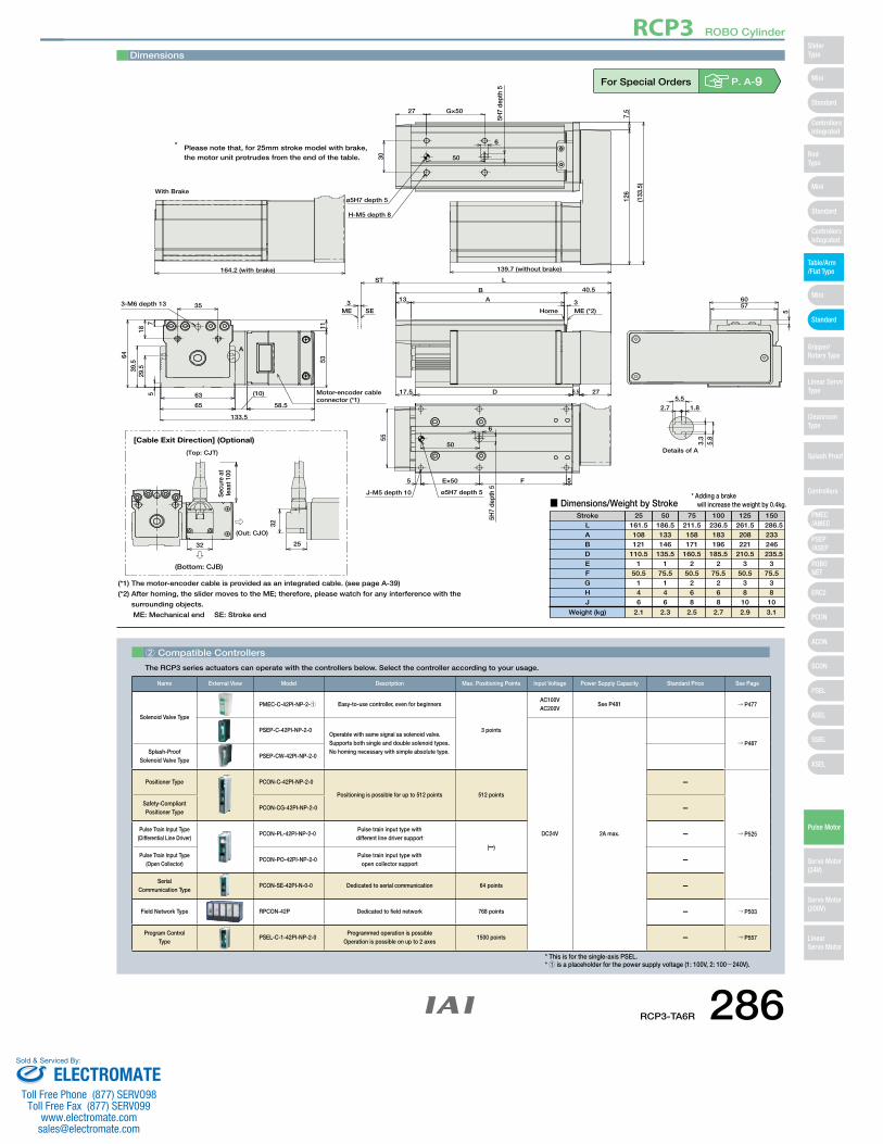
35
185
29.5
7
39.5
64
63
65
(10)
58.5
133.5
53
3-M6 depth 13
11
50
6
5H7
dept
h 5
5 E×50 F 5
55
J-M5 depth 10
5.8
3.3
1.82.7
5.5
164.2 (with brake)
With Brake
ø5H7 depth 5
Details of A
A
Motor-encoder cableconnector (*1)
126
7.5
139.7 (without brake)
6
27
30 50
5
6057
L
40.5B
A13
276.5D17.5
ST
33
G×50
5H7
dept
h 5
ø5H7 depth 5
H-M5 depth 8
(133
.5)
ME (*2)HomeSEME
[Cable Exit Direction] (Optional)
(Top: CJT)
32 25
32
(Out: CJO)
(Bottom: CJB)
Sec
ure
at
leas
t 100
(*1) The motor-encoder cable is provided as an integrated cable. (see page A-39)
(*2) After homing, the slider moves to the ME; therefore, please watch for any interference with the
surrounding objects.
ME: Mechanical end SE: Stroke end
* Adding a brake will increase the weight by 0.4kg.
Stroke 25 50 75 100 125 150
■ Dimensions/Weight by Stroke
161.5 186.5 211.5 236.5 261.5 286.5108 133 158 183 208 233 121 146 171 196 221 246
110.5 135.5 160.5 185.5 210.5 235.51 1 2 2 3 3
50.5 75.5 50.5 75.5 50.5 75.5 1 1 2 2 3 3 4 4 6 6 8 8 6 6 8 8 10 10
2.1 2.3 2.5 2.7 2.9 3.1
LABDEFGHJ
Weight (kg)
* Please note that, for 25mm stroke model with brake, the motor unit protrudes from the end of the table.
Dimensions
For Special Orders P. A-9
2 Compatible Controllers
The RCP3 series actuators can operate with the controllers below. Select the controller according to your usage.
Name External View Model Description Max. Positioning Points Input Voltage Power Supply Capacity Standard Price See Page
Solenoid Valve Type
PMEC-C-42PI-NP-2-1 Easy-to-use controller, even for beginners
3 points
AC100VAC200V
See P481 → P477
PSEP-C-42PI-NP-2-0Operable with same signal as solenoid valve.Supports both single and double solenoid types.No homing necessary with simple absolute type.
DC24V 2A max.
→ P487Splash-Proof
Solenoid Valve TypePSEP-CW-42PI-NP-2-0
Positioner Type PCON-C-42PI-NP-2-0
Positioning is possible for up to 512 points 512 points
–
→ P525
Safety-Compliant Positioner Type
PCON-CG-42PI-NP-2-0 –
Pulse Train Input Type(Differential Line Driver)
PCON-PL-42PI-NP-2-0Pulse train input type with different line driver support
(–)
–
Pulse Train Input Type(Open Collector)
PCON-PO-42PI-NP-2-0Pulse train input type with
open collector support–
Serial Communication Type
PCON-SE-42PI-N-0-0 Dedicated to serial communication 64 points –
Field Network Type RPCON-42P Dedicated to field network 768 points – → P503
Program Control Type
PSEL-C-1-42PI-NP-2-0Programmed operation is possible
Operation is possible on up to 2 axes1500 points – → P557
* This is for the single-axis PSEL.* 1 is a placeholder for the power supply voltage (1: 100V, 2: 100~240V).
RCP3-TA6R 286
RCP3 ROBO Cylinder
Mini
Mini
PSEP/ASEP
PMEC/AMEC
ROBONET
ERC2
PCON
ACON
SCON
PSEL
ASEL
SSEL
XSEL
Standard
Mini
Standard
Standard
ControllersIntegrated
ControllersIntegrated
SliderType
RodType
Table/Arm/Flat Type
Gripper/Rotary Type
Linear ServoType
Cleanroom Type
Splash Proof
Controllers
Pulse Motor
Servo Motor (24V)
Servo Motor (200V)
LinearServo Motor
ELECTROMATEToll Free Phone (877) SERVO98
Toll Free Fax (877) SERV099www.electromate.com
Sold & Serviced By:
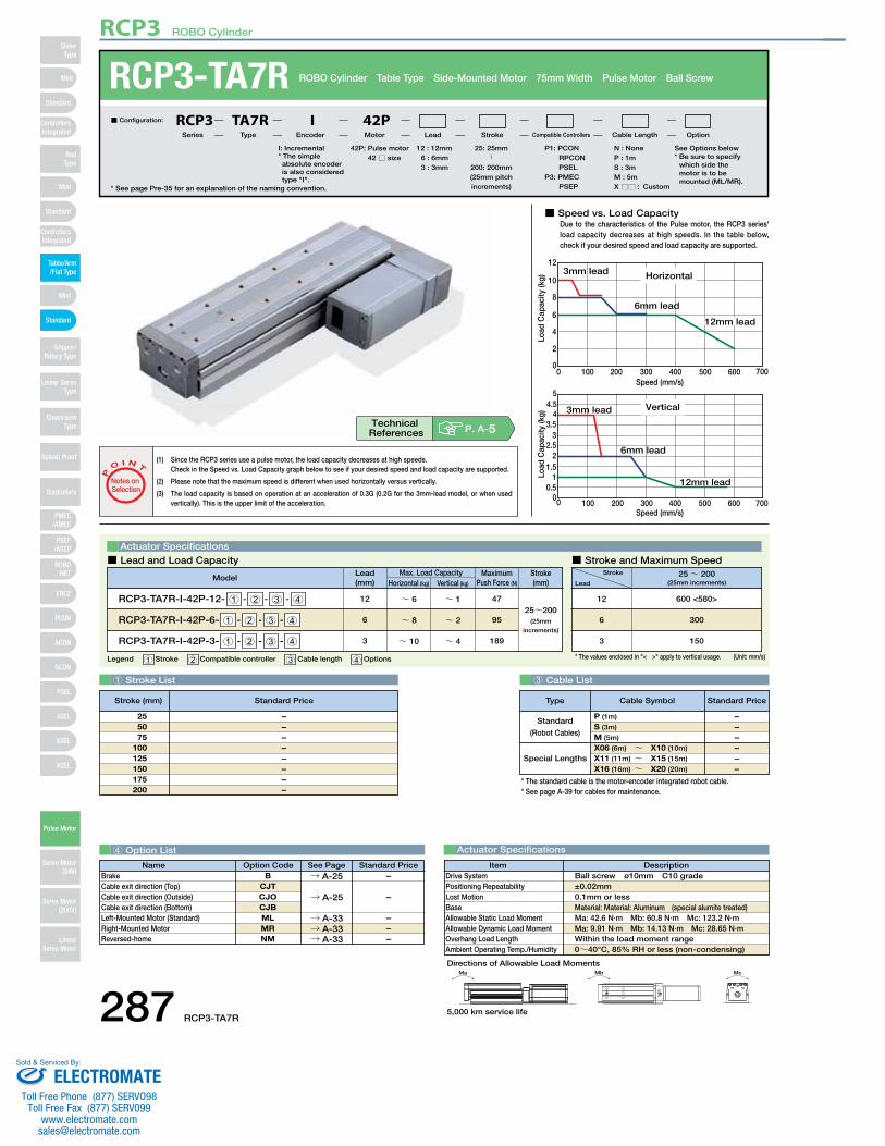
RCP3-TA7R ROBO Cylinder Table Type Side-Mounted Motor 75mm Width Pulse Motor Ball Screw
Special Lengths
Type Standard PriceCable Symbol
Standard
(Robot Cables)
P (1m)
S (3m)
M (5m)
X06 (6m) ~ X10 (10m)
X11 (11m) ~ X15 (15m)
X16 (16m) ~ X20 (20m)
––––––
Ma Mb Mc
Directions of Allowable Load Moments
■ Speed vs. Load CapacityDue to the characteristics of the Pulse motor, the RCP3 series' load capacity decreases at high speeds. In the table below, check if your desired speed and load capacity are supported.
0
2
4
6
10
8
12
0 100 200 300 400 500 600 700Speed (mm/s)
Horizontal3mm lead
6mm lead
Load
Cap
acity
(kg)
12mm lead
0 100 200 300 400 500 600 7000
0.51
1.52
2.53
3.54
4.55
Speed (mm/s)
Vertical3mm lead
6mm lead
Load
Cap
acity
(kg)
12mm lead
1 Stroke List 3 Cable List
4 Option List Actuator Specifications
DescriptionItemBall screw ø10mm C10 grade±0.02mm0.1mm or lessMaterial: Material: Aluminum (special alumite treated)Ma: 42.6 N∙m Mb: 60.8 N∙m Mc: 123.2 N∙mMa: 9.91 N∙m Mb: 14.13 N∙m Mc: 28.65 N∙mWithin the load moment range0~40°C, 85% RH or less (non-condensing)
Drive SystemPositioning RepeatabilityLost MotionBaseAllowable Static Load MomentAllowable Dynamic Load MomentOverhang Load LengthAmbient Operating Temp./Humidity
* See page Pre-35 for an explanation of the naming convention.
42P: Pulse motor 42 □ size
P1: PCON RPCON PSEL
P3: PMEC PSEP
N : NoneP : 1mS : 3mM : 5mX □□ : Custom
25: 25mm〜
200: 200mm(25mm pitch increments)
12 : 12mm6 : 6mm3 : 3mm
■ Configuration: RCP3 TA7R I 42PSeries Type Encoder Motor Lead Stroke Compatible Controllers Cable Length Option
Legend 1 Stroke 2 Compatible controller 3 Cable length 4 Options (Unit: mm/s)* The values enclosed in "< >" apply to vertical usage.
Actuator Specifications
■ Lead and Load Capacity ■ Stroke and Maximum Speed
(1) Since the RCP3 series use a pulse motor, the load capacity decreases at high speeds.Check in the Speed vs. Load Capacity graph below to see if your desired speed and load capacity are supported.
(2) Please note that the maximum speed is different when used horizontally versus vertically.
(3) The load capacity is based on operation at an acceleration of 0.3G (0.2G for the 3mm-lead model, or when used vertically). This is the upper limit of the acceleration.
P
O I N T
Notes on Selection
––––––––
255075
100125150175200
Lead(mm)
12
6
3
Horizontal (kg)
~ 6
~ 8
~ 10
Vertical (kg)
Max. Load Capacity Maximum Push Force (N)
Model
~ 1
~ 2
~ 4
47
95
189
Stroke(mm)
RCP3-TA7R-I-42P-12- 1 - 2 - 3 - 4
RCP3-TA7R-I-42P-6- 1 - 2 - 3 - 4
RCP3-TA7R-I-42P-3- 1 - 2 - 3 - 4
25~200(25mm
increments)
Stroke
Lead25~ 200
(25mm increments)
600 <580>
300
150
12
6
3
P. A-5Technical References
I: Incremental* The simple absolute encoder is also considered type "I".
* The standard cable is the motor-encoder integrated robot cable.* See page A-39 for cables for maintenance.
Stroke (mm) Standard Price
See Options below* Be sure to specify
which side the motor is to be mounted (ML/MR).
Name Standard PriceOption Code See PageB
CJTCJOCJBMLMRNM
BrakeCable exit direction (Top)Cable exit direction (Outside)Cable exit direction (Bottom)Left-Mounted Motor (Standard)Right-Mounted MotorReversed-home
→ A-25
→ A-33→ A-33→ A-33
–
–––
→ A-25 –
5,000 km service life287 RCP3-TA7R
RCP3 ROBO Cylinder
Mini
Mini
PSEP/ASEP
PMEC/AMEC
ROBONET
ERC2
PCON
ACON
SCON
PSEL
ASEL
SSEL
XSEL
Standard
Mini
Standard
Standard
ControllersIntegrated
ControllersIntegrated
RodType
Table/Arm/Flat Type
Gripper/Rotary Type
Linear ServoType
Cleanroom Type
Splash Proof
Controllers
Pulse Motor
Servo Motor (24V)
Servo Motor (200V)
LinearServo Motor
SliderType
ELECTROMATEToll Free Phone (877) SERVO98
Toll Free Fax (877) SERV099www.electromate.com
Sold & Serviced By:
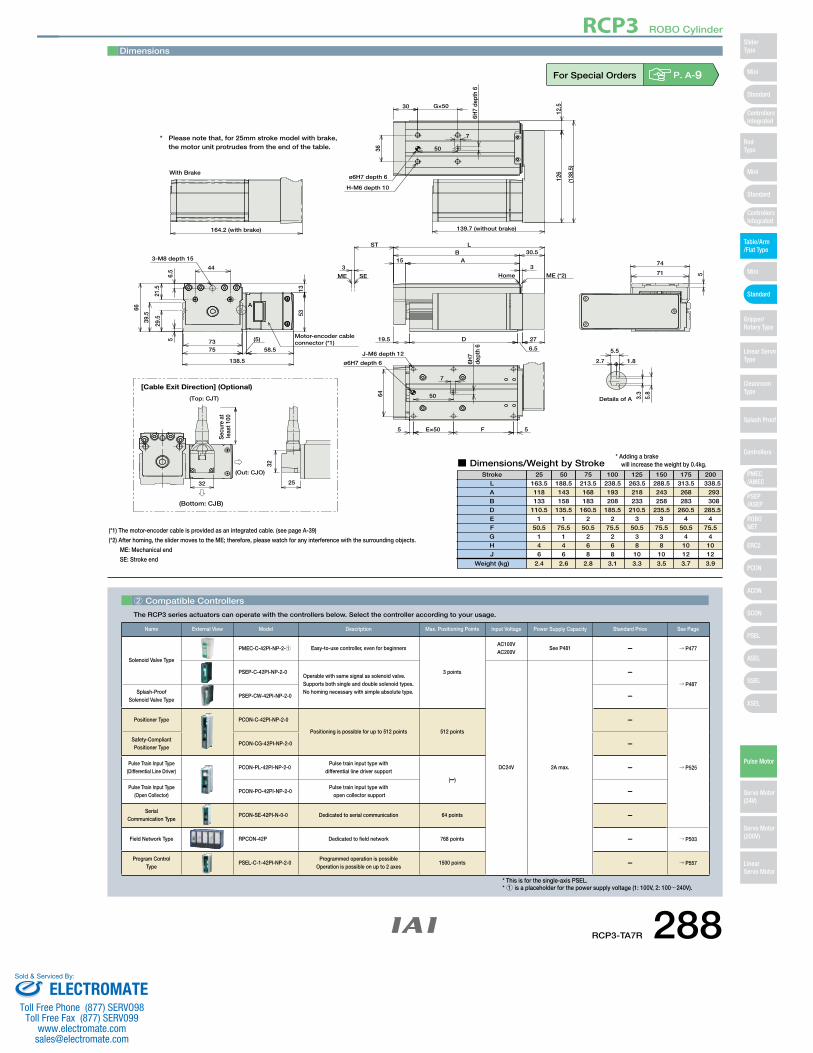
56.
5
21.5
29.539
.5
66
7375
(5)
58.5
138.5
53
44
3-M8 depth 15
13
5064
5 E×50 F 5
6H7
dept
h 6
7
J-M6 depth 12
3.3
5.8
1.82.7
5.5
164.2 (with brake)
With Brake
Details of A
ø6H7 depth 6
Motor-encoder cableconnector (*1)
A
12.5
126
7
36
30
50
5
74
71
6.5
30.5L
BA15
27D19.5
3
ST
3
G×50
6H7
dept
h 6
(138
.5)
139.7 (without brake)
ø6H7 depth 6
H-M6 depth 10
SEME ME (*2)Home
[Cable Exit Direction] (Optional)
(Top: CJT)
32 25
32
(Out: CJO)
(Bottom: CJB)
Sec
ure
at
leas
t 100
(*1) The motor-encoder cable is provided as an integrated cable. (see page A-39)
(*2) After homing, the slider moves to the ME; therefore, please watch for any interference with the surrounding objects.
ME: Mechanical end
SE: Stroke end
* Adding a brakewill increase the weight by 0.4kg.
Stroke 25 50 75 100 125 150 175 200
■ Dimensions/Weight by Stroke
163.5 188.5 213.5 238.5 263.5 288.5 313.5 338.5118 143 168 193 218 243 268 293133 158 183 208 233 258 283 308
110.5 135.5 160.5 185.5 210.5 235.5 260.5 285.51 1 2 2 3 3 4 4
50.5 75.5 50.5 75.5 50.5 75.5 50.5 75.5 1 1 2 2 3 3 4 4 4 4 6 6 8 8 10 10 6 6 8 8 10 10 12 12
2.4 2.6 2.8 3.1 3.3 3.5 3.7 3.9
LABDEFGHJ
Weight (kg)
* Please note that, for 25mm stroke model with brake, the motor unit protrudes from the end of the table.
Dimensions
For Special Orders P. A-9
2 Compatible Controllers
The RCP3 series actuators can operate with the controllers below. Select the controller according to your usage.
Name External View Model Description Max. Positioning Points Input Voltage Power Supply Capacity Standard Price See Page
Solenoid Valve Type
PMEC-C-42PI-NP-2-1 Easy-to-use controller, even for beginners
3 points
AC100VAC200V
See P481 – → P477
PSEP-C-42PI-NP-2-0Operable with same signal as solenoid valve.Supports both single and double solenoid types.No homing necessary with simple absolute type.
DC24V 2A max.
–→ P487
Splash-Proof Solenoid Valve Type
PSEP-CW-42PI-NP-2-0 –
Positioner Type PCON-C-42PI-NP-2-0
Positioning is possible for up to 512 points 512 points
–
→ P525
Safety-Compliant Positioner Type
PCON-CG-42PI-NP-2-0 –
Pulse Train Input Type(Differential Line Driver)
PCON-PL-42PI-NP-2-0Pulse train input type with
differential line driver support
(–)
–
Pulse Train Input Type(Open Collector)
PCON-PO-42PI-NP-2-0Pulse train input type with
open collector support–
Serial Communication Type
PCON-SE-42PI-N-0-0 Dedicated to serial communication 64 points –
Field Network Type RPCON-42P Dedicated to field network 768 points – → P503
Program Control Type
PSEL-C-1-42PI-NP-2-0Programmed operation is possible
Operation is possible on up to 2 axes1500 points – → P557
* This is for the single-axis PSEL.* 1 is a placeholder for the power supply voltage (1: 100V, 2: 100~240V).
RCP3-TA7R 288
RCP3 ROBO Cylinder
Mini
Mini
PSEP/ASEP
PMEC/AMEC
ROBONET
ERC2
PCON
ACON
SCON
PSEL
ASEL
SSEL
XSEL
Standard
Mini
Standard
Standard
ControllersIntegrated
ControllersIntegrated
SliderType
RodType
Table/Arm/Flat Type
Gripper/Rotary Type
Linear ServoType
Cleanroom Type
Splash Proof
Controllers
Pulse Motor
Servo Motor (24V)
Servo Motor (200V)
LinearServo Motor
ELECTROMATEToll Free Phone (877) SERVO98
Toll Free Fax (877) SERV099www.electromate.com
Sold & Serviced By:
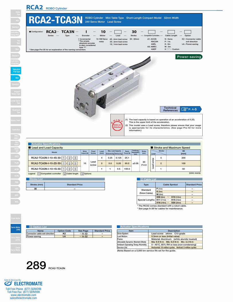
289 RCA2-TCA3N
RCA2 ROBO Cylinder
3 Option List
Lead
scr
ew
Lead
screw
Stroke List 2 Cable List
Actuator Specifications
RCA2-TCA3N ROBO Cylinder Mini Table Type Short-Length Compact Model 32mm Width
24V Servo Motor Lead Screw
Legend 1 Compatible controller 2 Cable length 3 Options
Actuator Specifications
Stroke
Lead
30(mm)
200
100
50
4
2
1
■ Lead and Load Capacity ■ Stroke and Maximum Speed
P
O I N T
Notes on Selection
(Unit: mm/s)
* See page Pre-35 for an explanation of the naming convention.
10: 10W Servo motor
I: Incremental* The simple absolute encoder is also considered type "I".
A1: ACON RACON ASEL
A3: AMEC ASEP
N : NoneP : 1mS : 3mM : 5mX □□ : Custom
K2 : Connector cable exit direction
LA : Power-saving
30 : 30mm4S : 4mm lead screw2S : 2mm lead screw1S : 1mm lead screw
■ Configuration: RCA2 TCA3N I 10 30Series Type Encoder Motor Lead Stroke Compatible Controllers Cable Length Option
Lead(mm)
Motor Output (W) Horizontal (kg) Vertical (kg)
Max. Load Capacity Positioning Repeatability
(mm)
Rated Thrust (N)
ModelStroke(mm)
RCA2-TCA3N-I-10-4S-30- 1 - 2 - 3
RCA2-TCA3N-I-10-2S-30- 1 - 2 - 3
RCA2-TCA3N-I-10-1S-30- 1 - 2 - 3
10
0.254
0.52
11
0.125
0.25
0.5
25.1
50.3
100.5
30(Fixed)
±0.05
* The RCA2 comes standard with a robot cable.* See page A-39 for cables for maintenance.
(Note) Based on a 5,000 km service life set for the guide.
Special Lengths
Type Standard PriceCable Symbol
Standard
(Robot Cables)
P (1m)
S (3m)
M (5m)
X06 (6m) ~ X10 (10m)
X11 (11m) ~ X15 (15m)
X16 (16m) ~ X20 (20m)
––––––
–30
DescriptionItemLead screw ø4mm C10 grade 0.3mm or less (initial value)Material: Aluminum (white alumite treated)Ma: 9.9 N∙m Mb: 9.9 N∙m Mc: 3.3 N∙m0~40°C, 85% RH or less (non-condensing)Horizontal: 10 million cycles Vertical: 5 million cycles
Drive SystemLost MotionFrameAllowable Dynamic Moment (Note)Ambient Operating Temp./HumidityService Life
(1) The load capacity is based on operation at an acceleration of 0.2G.This is the upper limit of the acceleration.
(2) This model uses a Lead screw, therefore please ensure that your usage is appropriate for its characteristics. (See page Pre-42 for more information.)
Feed Screw
Name Standard PriceOption Code See PageK2LA
→ A-32→ A-32
Connector cable exit directionPower-saving
––
P. A-5Technical References
Stroke (mm) Standard Price
Power-saving
Mini
Mini
PSEP/ASEP
PMEC/AMEC
ROBONET
ERC2
PCON
ACON
SCON
PSEL
ASEL
SSEL
XSEL
Standard
Mini
Standard
Standard
ControllersIntegrated
ControllersIntegrated
RodType
Table/Arm/Flat Type
Gripper/Rotary Type
Linear ServoType
Cleanroom Type
Splash Proof
Controllers
Pulse Motor
Servo Motor (24V)
Servo Motor (200V)
LinearServo Motor
SliderType
ELECTROMATEToll Free Phone (877) SERVO98
Toll Free Fax (877) SERV099www.electromate.com
Sold & Serviced By:
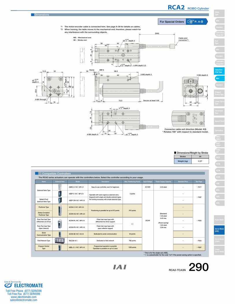
RCA2-TCA3N 290
RCA2 ROBO Cylinder
10.5
4
16
16
3245
23
22.6
4-M4 through
30+0
.05 de
pth
3
ø3 0+0.03
depth 3 31
43
7
302
86.5
8 8 73.5
ME*2Home
22 4
30
223
2-M4 depth 6
4
206
6
4046
26
ø3 0+0.03
depth 3
3 0+0.05depth 3 4-M4 depth 5.5
4
195.
57.
5
3010
25
ø3 0+0.03
depth 34-M4 depth 4
3 0+0.05
depth 3
Secure at least 100
(300)
ME : Mechanical end
SE : Stroke end
Connector cable exit direction (Model: K2)* Rotates 180° with respect to standard model.
Cable jointconnector*1
7 2-M3 depth 326 40
Dimensions
*1 The motor-encoder cable is connected here. See page A-39 for details on cables.
*2 When homing, the table moves to the mechanical end; therefore, please watch for
any interference with the surrounding objects.
■ Dimensions/Weight by Stroke
Weight (kg)
Stroke
0.37
30
For Special Orders P. A-9
1 Compatible Controllers
The RCA2 series actuators can operate with the controllers below. Select the controller according to your usage.
* This is for the single-axis ASEL.* 1 is a placeholder for the code "LA" if the power-saving option is specified.
Name External View Model Description Max. Positioning Points Input Voltage Power Supply Capacity Standard Price See Page
Solenoid Valve Type
AMEC-C-10I1-NP-2-1 Easy-to-use controller, even for beginners
3 points
AC100V 2.4A rated – → P477
ASEP-C-10I1-NP-2-0Operable with same signal as solenoid valve.Supports both single and double solenoid types.No homing necessary with simple absolute type.
DC24V
(Standard)1.3A rated4.4A max.
(Power-saving)1.3A rated2.5A max.
–
→ P487Splash-Proof
Solenoid Valve TypeASEP-CW-10I1-NP-2-0 –
Positioner Type ACON-C-10I1-NP-2-0
Positioning is possible for up to 512 points 512 points
–
→ P535
Safety-Compliant Positioner Type
ACON-CG-10I1-NP-2-0 –
Pulse Train Input Type(Differential Line Driver)
ACON-PL-10I1-NP-2-0Pulse train input type with
differential line driver support(−)
–
Pulse Train Input Type(Open Collector)
ACON-PO-10I1-NP-2-0Pulse train input type with
open collector support–
Serial Communication Type
ACON-SE-10I1-N-0-0 Dedicated to serial communication 64 points –
Field Network Type RACON-101 Dedicated to field network 768 points – → P503
Program Control Type
ASEL-C-1-10I1-NP-2-0Programmed operation is possible
Operation is possible on up to 2 axes1500 points – → P567
Mini
Mini
PSEP/ASEP
PMEC/AMEC
ROBONET
ERC2
PCON
ACON
SCON
PSEL
ASEL
SSEL
XSEL
Standard
Mini
Standard
Standard
ControllersIntegrated
ControllersIntegrated
SliderType
RodType
Table/Arm/Flat Type
Gripper/Rotary Type
Linear ServoType
Cleanroom Type
Splash Proof
Controllers
Pulse Motor
Servo Motor (24V)
Servo Motor (200V)
LinearServo Motor
ELECTROMATEToll Free Phone (877) SERVO98
Toll Free Fax (877) SERV099www.electromate.com
Sold & Serviced By:
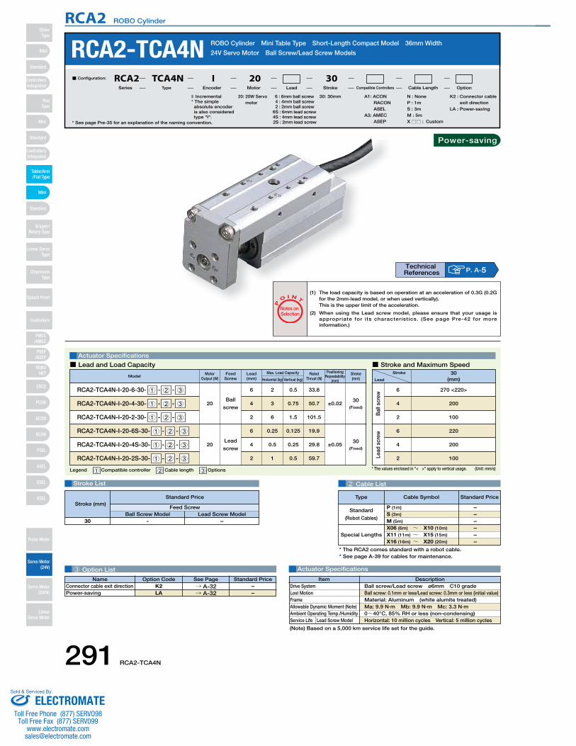
291 RCA2-TCA4N
RCA2 ROBO Cylinder
* The values enclosed in "< >" apply to vertical usage.
Bal
l scr
ewLe
ad s
crew
6
2
4
220
200
100
Ball
screw
Lead
screw
RCA2-TCA4N ROBO Cylinder Mini Table Type Short-Length Compact Model 36mm Width
24V Servo Motor Ball Screw/Lead Screw Models
* See page Pre-35 for an explanation of the naming convention.
20: 20W Servo motor
I: Incremental* The simple absolute encoder is also considered type "I".
A1: ACON RACON ASEL
A3: AMEC ASEP
N : NoneP : 1mS : 3mM : 5mX □□ : Custom
K2 : Connector cable exit direction
LA : Power-saving
30: 30mm6 : 6mm ball screw4 : 4mm ball screw2 : 2mm ball screw
6S : 6mm lead screw4S : 4mm lead screw2S : 2mm lead screw
■ Configuration: RCA2 TCA4N I 20 30Series Type Encoder Motor Lead Stroke Compatible Controllers Cable Length Option
3 Option List
Stroke List 2 Cable List
Actuator Specifications
Legend 1 Compatible controller 2 Cable length 3 Options
Actuator Specifications
Stroke
Lead
30(mm)
270 <220>
200
100
6
4
2
■ Lead and Load Capacity ■ Stroke and Maximum Speed
P
O I N T
Notes on Selection
(Unit: mm/s)
Lead(mm)
Motor Output (W) Horizontal (kg) Vertical (kg)
Max. Load Capacity Positioning Repeatability
(mm)
Rated Thrust (N)
ModelStroke(mm)
RCA2-TCA4N-I-20-6-30- 1 - 2 - 3
RCA2-TCA4N-I-20-4-30- 1 - 2 - 3
RCA2-TCA4N-I-20-2-30- 1 - 2 - 3
20
26
34
62
0.5
0.75
1.5
33.8
50.7
101.5
30(Fixed)
±0.02
RCA2-TCA4N-I-20-6S-30- 1 - 2 - 3
RCA2-TCA4N-I-20-4S-30- 1 - 2 - 3
RCA2-TCA4N-I-20-2S-30- 1 - 2 - 3
20
0.256
0.54
12
0.125
0.25
0.5
19.9
29.8
59.7
30(Fixed)
±0.05
* The RCA2 comes standard with a robot cable.* See page A-39 for cables for maintenance.
Special Lengths
Type Standard PriceCable Symbol
Standard
(Robot Cables)
P (1m)
S (3m)
M (5m)
X06 (6m) ~ X10 (10m)
X11 (11m) ~ X15 (15m)
X16 (16m) ~ X20 (20m)
––––––
- –
Feed ScrewBall Screw Model Lead Screw Model
30
DescriptionItemBall screw/Lead screw ø6mm C10 grade Ball screw: 0.1mm or less/Lead screw: 0.3mm or less (initial value)Material: Aluminum (white alumite treated)Ma: 9.9 N∙m Mb: 9.9 N∙m Mc: 3.3 N∙m0~40°C, 85% RH or less (non-condensing)Horizontal: 10 million cycles Vertical: 5 million cycles
Drive SystemLost MotionFrameAllowable Dynamic Moment (Note)Ambient Operating Temp./HumidityService Life Lead Screw Model
(1) The load capacity is based on operation at an acceleration of 0.3G (0.2G for the 2mm-lead model, or when used vertically).This is the upper limit of the acceleration.
(2) When using the Lead screw model, please ensure that your usage is appropriate for its characteristics. (See page Pre-42 for more information.)
Feed Screw
(Note) Based on a 5,000 km service life set for the guide.
Name Standard PriceOption Code See PageK2LA
→ A-32→ A-32
Connector cable exit directionPower-saving
––
P. A-5Technical References
Stroke (mm)Standard Price
Power-saving
Mini
Mini
PSEP/ASEP
PMEC/AMEC
ROBONET
ERC2
PCON
ACON
SCON
PSEL
ASEL
SSEL
XSEL
Standard
Mini
Standard
Standard
ControllersIntegrated
ControllersIntegrated
RodType
Table/Arm/Flat Type
Gripper/Rotary Type
Linear ServoType
Cleanroom Type
Splash Proof
Controllers
Pulse Motor
Servo Motor (24V)
Servo Motor (200V)
LinearServo Motor
SliderType
ELECTROMATEToll Free Phone (877) SERVO98
Toll Free Fax (877) SERV099www.electromate.com
Sold & Serviced By:
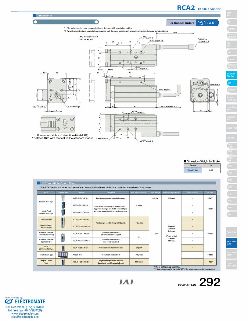
RCA2-TCA4N 292
RCA2 ROBO Cylinder
10.5
4
36
51
20
20
24
34
4-M4 through
22.6
30+0
.05 de
pth
3
ø3 0+0.03depth 3
7
30
2
95
80810
4
227
7
48
40284-M4 depth 5.5
ø3 0+0.03
depth 3
3 0+0.05
depth 3ME*2Home
4
216.
58.
5
25
10 304-M4 depth 5
ø3 0+0.03
depth 3
3 0+0.05
depth 326 4
426
2-M4 depth 8
ME: Mechanical end
Secure at least 100
(300)
Cable jointconnector *1
Connector cable exit direction (Model: K2)* Rotates 180° with respect to the standard model.
2-M3 depth 4
728 40
SE: Stroke end
Dimensions
■ Dimensions/Weight by Stroke
Weight (kg)
Stroke
0.48
30
For Special Orders P. A-9*1 The motor-encoder cable is connected here. See page A-39 for details on cables.
*2 When homing, the table moves to the mechanical end; therefore, please watch for any interference with the surrounding objects.
1 Compatible Controllers
The RCA2 series actuators can operate with the controllers below. Select the controller according to your usage.
* This is for the single-axis ASEL.* 1 is a placeholder for the code "LA" if the power-saving option is specified.
Name External View Model Description Max. Positioning Points Input Voltage Power Supply Capacity Standard Price See Page
Solenoid Valve Type
AMEC-C-20I1-NP-2-1 Easy-to-use controller, even for beginners
3 points
AC100V 2.4A rated – → P477
ASEP-C-20I1-NP-2-0Operable with same signal as solenoid valve.Supports both single and double solenoid types.No homing necessary with simple absolute type.
DC24V
(Standard)1.3A rated4.4A max.
(Power-saving)1.3A rated2.5A max.
–
→ P487Splash-Proof
Solenoid Valve TypeASEP-CW-20I1-NP-2-0 –
Positioner Type ACON-C-20I1-NP-2-0
Positioning is possible for up to 512 points 512 points
–
→ P535
Safety-Compliant Positioner Type
ACON-CG-20I1-NP-2-0 –
Pulse Train Input Type(Differential Line Driver)
ACON-PL-20I1-NP-2-0Pulse train input type with
differential line driver support(−)
–
Pulse Train Input Type(Open Collector)
ACON-PO-20I1-NP-2-0Pulse train input type with
open collector support–
Serial Communication Type
ACON-SE-20I1-N-0-0 Dedicated to serial communication 64 points –
Field Network Type RACON-201 Dedicated to field network 768 points – → P503
Program Control Type
ASEL-C-1-20I1-NP-2-0Programmed operation is possible
Operation is possible on up to 2 axes1500 points – → P567
Mini
Mini
PSEP/ASEP
PMEC/AMEC
ROBONET
ERC2
PCON
ACON
SCON
PSEL
ASEL
SSEL
XSEL
Standard
Mini
Standard
Standard
ControllersIntegrated
ControllersIntegrated
SliderType
RodType
Table/Arm/Flat Type
Gripper/Rotary Type
Linear ServoType
Cleanroom Type
Splash Proof
Controllers
Pulse Motor
Servo Motor (24V)
Servo Motor (200V)
LinearServo Motor
ELECTROMATEToll Free Phone (877) SERVO98
Toll Free Fax (877) SERV099www.electromate.com
Sold & Serviced By:
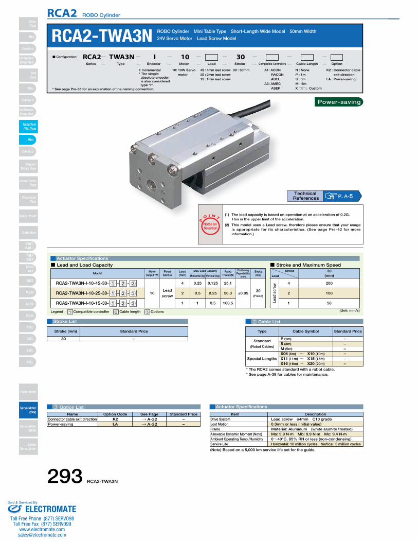
293 RCA2-TWA3N
RCA2 ROBO Cylinder
3 Option List
Lead
scr
ew
Lead
screw
Stroke List 2 Cable List
Actuator Specifications
RCA2-TWA3N ROBO Cylinder Mini Table Type Short-Length Wide Model 50mm Width
24V Servo Motor Lead Screw Model
Legend 1 Compatible controller 2 Cable length 3 Options
Actuator Specifications
Stroke
Lead
30(mm)
200
100
50
4
2
1
■ Lead and Load Capacity ■ Stroke and Maximum Speed
P
O I N T
Notes on Selection
(Unit: mm/s)
* See page Pre-35 for an explanation of the naming convention.
10: 10W Servo motor
I: Incremental* The simple absolute encoder is also considered type "I".
A1: ACON RACON ASEL
A3: AMEC ASEP
N : NoneP : 1mS : 3mM : 5mX □□ : Custom
K2 : Connector cable exit direction
LA : Power-saving
30 : 30mm4S : 4mm lead screw2S : 2mm lead screw1S : 1mm lead screw
■ Configuration: RCA2 TWA3N I 10 30Series Type Encoder Motor Lead Stroke Compatible Controllers Cable Length Option
Lead(mm)
Motor Output (W) Horizontal (kg) Vertical (kg)
Max. Load Capacity Positioning Repeatability
(mm)
Rated Thrust (N)
ModelStroke(mm)
RCA2-TWA3N-I-10-4S-30- 1 - 2 - 3
RCA2-TWA3N-I-10-2S-30- 1 - 2 - 3
RCA2-TWA3N-I-10-1S-30- 1 - 2 - 3
10
0.254
0.52
11
0.125
0.25
0.5
25.1
50.3
100.5
30(Fixed)
±0.05
* The RCA2 comes standard with a robot cable.* See page A-39 for cables for maintenance.
Special Lengths
Type Standard PriceCable Symbol
Standard
(Robot Cables)
P (1m)
S (3m)
M (5m)
X06 (6m) ~ X10 (10m)
X11 (11m) ~ X15 (15m)
X16 (16m) ~ X20 (20m)
––––––
–30
DescriptionItemLead screw ø4mm C10 grade 0.3mm or less (initial value)Material: Aluminum (white alumite treated)Ma: 9.9 N∙m Mb: 9.9 N∙m Mc: 9.4 N∙m0~40°C, 85% RH or less (non-condensing)Horizontal: 10 million cycles Vertical: 5 million cycles
Drive SystemLost MotionFrameAllowable Dynamic Moment (Note)Ambient Operating Temp./HumidityService Life
(1) The load capacity is based on operation at an acceleration of 0.2G.This is the upper limit of the acceleration.
(2) This model uses a Lead screw, therefore please ensure that your usage is appropriate for its characteristics. (See page Pre-42 for more information.)
Feed Screw
(Note) Based on a 5,000 km service life set for the guide.
Name Standard PriceOption Code See PageK2LA
→ A-32→ A-32
Connector cable exit directionPower-saving
––
P. A-5Technical References
Stroke (mm) Standard Price
Power-saving
Mini
Mini
PSEP/ASEP
PMEC/AMEC
ROBONET
ERC2
PCON
ACON
SCON
PSEL
ASEL
SSEL
XSEL
Standard
Mini
Standard
Standard
ControllersIntegrated
ControllersIntegrated
RodType
Table/Arm/Flat Type
Gripper/Rotary Type
Linear ServoType
Cleanroom Type
Splash Proof
Controllers
Pulse Motor
Servo Motor (24V)
Servo Motor (200V)
LinearServo Motor
SliderType
ELECTROMATEToll Free Phone (877) SERVO98
Toll Free Fax (877) SERV099www.electromate.com
Sold & Serviced By:

RCA2-TWA3N 294
RCA2 ROBO Cylinder
302
8 8
86.5
73.5
Home ME*2
40
223
9
3-M4 depth 6 5 10.5
4
50
43
26
1621
41
4-M4
through
29
30+0
.05 de
pth
3
ø3 0+0.03depth 3
12
4
40
376.
5
26
46
4-M4 depth 6.5ø3 0
+0.03depth 3
3 0+0.05
depth 3
4
30
37
10254-M4 depth 6
3 0+0.05depth 3
ø3 0+0.03
depth 3
6.5
Secure at least 100
(300)
ME: Mechanical end
Connector cable exit direction (Model: K2)* Rotates 180° with respect to the standard model.
Cable jointconnector*1SE: Stroke end
Dimensions
■ Dimensions/Weight by Stroke
Weight (kg)
Stroke
0.52
30
For Special Orders P. A-9*1 The motor-encoder cable is connected here. See page A-39 for details on cables.
*2 When homing, the table moves to the mechanical end; therefore, please watch for any interference with the surrounding objects.
1 Compatible Controllers
The RCA2 series actuators can operate with the controllers below. Select the controller according to your usage.
* This is for the single-axis ASEL.* 1 is a placeholder for the code "LA" if the power-saving option is specified.
Name External View Model Description Max. Positioning Points Input Voltage Power Supply Capacity Standard Price See Page
Solenoid Valve Type
AMEC-C-10I1-NP-2-1 Easy-to-use controller, even for beginners
3 points
AC100V 2.4A rated – → P477
ASEP-C-10I1-NP-2-0Operable with same signal as solenoid valve.Supports both single and double solenoid types.No homing necessary with simple absolute type.
DC24V
(Standard)1.3A rated4.4A max.
(Power-saving)1.3A rated2.5A max.
–
→ P487Splash-Proof
Solenoid Valve TypeASEP-CW-10I1-NP-2-0 –
Positioner Type ACON-C-10I1-NP-2-0
Positioning is possible for up to 512 points 512 points
–
→ P535
Safety-Compliant Positioner Type
ACON-CG-10I1-NP-2-0 –
Pulse Train Input Type(Differential Line Driver)
ACON-PL-10I1-NP-2-0Pulse train input type with
differential line driver support(−)
–
Pulse Train Input Type(Open Collector)
ACON-PO-10I1-NP-2-0Pulse train input type with
open collector support–
Serial Communication Type
ACON-SE-10I1-N-0-0 Dedicated to serial communication 64 points –
Field Network Type RACON-101 Dedicated to field network 768 points – → P503
Program Control Type
ASEL-C-1-10I1-NP-2-0Programmed operation is possible
Operation is possible on up to 2 axes1500 points – → P567
Mini
Mini
PSEP/ASEP
PMEC/AMEC
ROBONET
ERC2
PCON
ACON
SCON
PSEL
ASEL
SSEL
XSEL
Standard
Mini
Standard
Standard
ControllersIntegrated
ControllersIntegrated
SliderType
RodType
Table/Arm/Flat Type
Gripper/Rotary Type
Linear ServoType
Cleanroom Type
Splash Proof
Controllers
Pulse Motor
Servo Motor (24V)
Servo Motor (200V)
LinearServo Motor
ELECTROMATEToll Free Phone (877) SERVO98
Toll Free Fax (877) SERV099www.electromate.com
Sold & Serviced By:
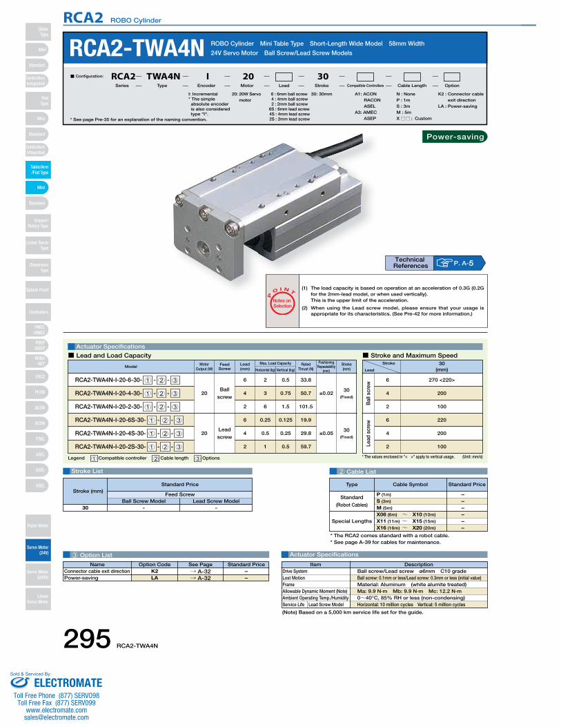
295 RCA2-TWA4N
RCA2 ROBO Cylinder
* The values enclosed in "< >" apply to vertical usage.
Bal
l scr
ewLe
ad s
crew
6
2
4
220
200
100
Ball
screw
Lead
screw
RCA2-TWA4N ROBO Cylinder Mini Table Type Short-Length Wide Model 58mm Width
24V Servo Motor Ball Screw/Lead Screw Models
* See page Pre-35 for an explanation of the naming convention.
20: 20W Servo motor
I: Incremental* The simple absolute encoder is also considered type "I".
A1: ACON RACON ASEL
A3: AMEC ASEP
N : NoneP : 1mS : 3mM : 5mX □□ : Custom
K2 : Connector cable exit direction
LA : Power-saving
30: 30mm6 : 6mm ball screw4 : 4mm ball screw2 : 2mm ball screw
6S : 6mm lead screw4S : 4mm lead screw2S : 2mm lead screw
■ Configuration: RCA2 TWA4N I 20 30Series Type Encoder Motor Lead Stroke Compatible Controllers Cable Length Option
3 Option List
Stroke List 2 Cable List
Actuator Specifications
Legend 1 Compatible controller 2 Cable length 3 Options
Actuator Specifications
Stroke
Lead
30(mm)
270 <220>
200
100
6
4
2
■ Lead and Load Capacity ■ Stroke and Maximum Speed
P
O I N T
Notes on Selection
(Unit: mm/s)
Lead(mm)
Motor Output (W) Horizontal (kg) Vertical (kg)
Max. Load Capacity Positioning Repeatability
(mm)
Rated Thrust (N)
ModelStroke(mm)
RCA2-TWA4N-I-20-6-30- 1 - 2 - 3
RCA2-TWA4N-I-20-4-30- 1 - 2 - 3
RCA2-TWA4N-I-20-2-30- 1 - 2 - 3
20
26
34
62
0.5
0.75
1.5
33.8
50.7
101.5
30(Fixed)
±0.02
RCA2-TWA4N-I-20-6S-30- 1 - 2 - 3
RCA2-TWA4N-I-20-4S-30- 1 - 2 - 3
RCA2-TWA4N-I-20-2S-30- 1 - 2 - 3
20
0.256
0.54
12
0.125
0.25
0.5
19.9
29.8
59.7
30(Fixed)
±0.05
* The RCA2 comes standard with a robot cable.* See page A-39 for cables for maintenance.
Special Lengths
Type Standard PriceCable Symbol
Standard
(Robot Cables)
P (1m)
S (3m)
M (5m)
X06 (6m) ~ X10 (10m)
X11 (11m) ~ X15 (15m)
X16 (16m) ~ X20 (20m)
––––––
DescriptionItemBall screw/Lead screw ø6mm C10 grade Ball screw: 0.1mm or less/Lead screw: 0.3mm or less (initial value)Material: Aluminum (white alumite treated)Ma: 9.9 N∙m Mb: 9.9 N∙m Mc: 12.2 N∙m0~40°C, 85% RH or less (non-condensing)Horizontal: 10 million cycles Vertical: 5 million cycles
Drive SystemLost MotionFrameAllowable Dynamic Moment (Note)Ambient Operating Temp./HumidityService Life Lead Screw Model
(1) The load capacity is based on operation at an acceleration of 0.3G (0.2G for the 2mm-lead model, or when used vertically).This is the upper limit of the acceleration.
(2) When using the Lead screw model, please ensure that your usage is appropriate for its characteristics. (See Pre-42 for more information.)
Feed Screw
(Note) Based on a 5,000 km service life set for the guide.
Name Standard PriceOption Code See PageK2LA
→ A-32→ A-32
Connector cable exit directionPower-saving
––
P. A-5Technical References
- -
Feed ScrewBall Screw Model Lead Screw Model
30
Stroke (mm)Standard Price
Power-saving
Mini
Mini
PSEP/ASEP
PMEC/AMEC
ROBONET
ERC2
PCON
ACON
SCON
PSEL
ASEL
SSEL
XSEL
Standard
Mini
Standard
Standard
ControllersIntegrated
ControllersIntegrated
RodType
Table/Arm/Flat Type
Gripper/Rotary Type
Linear ServoType
Cleanroom Type
Splash Proof
Controllers
Pulse Motor
Servo Motor (24V)
Servo Motor (200V)
LinearServo Motor
SliderType
ELECTROMATEToll Free Phone (877) SERVO98
Toll Free Fax (877) SERV099www.electromate.com
Sold & Serviced By:

RCA2-TWA4N 296
RCA2 ROBO Cylinder
302
95
8010 8
Home ME*2
5012
264
3-M4 depth 8 4 10.5
4
58
4846
2021
30
30+0.0
5 dept
h 3
ø3 0+0.03
depth 3
31
14 4-M4 through 4
45
2530104-M4 depth 8
ø3 0+0.03
depth 3
3 0+0.05
depth 3
6.5
4
4028
456.
5
48
4-M4 depth 7
ø3 0+0.03
depth 3
3 0+0.05 depth 3
Secure at least 100
ME: Mechanical end
(300)
Connector cable exit direction (Model: K2)* Rotates 180° with respect to the standard model.
Cable jointconnector*1SE: Stroke end
Dimensions
■ Dimensions/Weight by Stroke
Weight (kg)
Stroke
0.65
30
For Special Orders P. A-9*1 The motor-encoder cable is connected here. See page A-39 for details on cables.
*2 When homing, the table moves to the mechanical end; therefore, please watch for
any interference with the surrounding objects.
1 Compatible Controllers
The RCA2 series actuators can operate with the controllers below. Select the controller according to your usage.
* This is for the single-axis ASEL.* 1 is a placeholder for the code "LA" if the power-saving option is specified.
Name External View Model Description Max. Positioning Points Input Voltage Power Supply Capacity Standard Price See Page
Solenoid Valve Type
AMEC–C–20I1–NP–2–1 Easy–to–use controller, even for beginners
3 points
AC100V 2.4A rated – → P477
ASEP-C-20I1-NP-2-0Operable with same signal as solenoid valve.Supports both single and double solenoid types.No homing necessary with simple absolute type.
DC24V
(Standard)1.3A rated4.4A max.
(Power-saving)1.3A rated2.5A max.
–
→ P487Splash-Proof
Solenoid Valve TypeASEP-CW-20I1-NP-2-0 –
Positioner Type ACON-C-20I1-NP-2-0
Positioning is possible for up to 512 points 512 points
–
→ P535
Safety-Compliant Positioner Type
ACON-CG-20I1-NP-2-0 –
Pulse Train Input Type(Differential Line Driver)
ACON-PL-20I1-NP-2-0Pulse train input type with
differential line driver support(−)
–
Pulse Train Input Type(Open Collector)
ACON-PO-20I1-NP-2-0Pulse train input type with
open collector support–
Serial Communication Type
ACON-SE-20I1-N-0-0 Dedicated to serial communication 64 points –
Field Network Type RACON-201 Dedicated to field network 768 points – → P503
Program Control Type
ASEL-C-1-20I1-NP-2-0Programmed operation is possible
Operation is possible on up to 2 axes1500 points – → P567
Mini
Mini
PSEP/ASEP
PMEC/AMEC
ROBONET
ERC2
PCON
ACON
SCON
PSEL
ASEL
SSEL
XSEL
Standard
Mini
Standard
Standard
ControllersIntegrated
ControllersIntegrated
SliderType
RodType
Table/Arm/Flat Type
Gripper/Rotary Type
Linear ServoType
Cleanroom Type
Splash Proof
Controllers
Pulse Motor
Servo Motor (24V)
Servo Motor (200V)
LinearServo Motor
ELECTROMATEToll Free Phone (877) SERVO98
Toll Free Fax (877) SERV099www.electromate.com
Sold & Serviced By:

297 RCA2-TFA3N
RCA2 ROBO Cylinder
3 Option List
Lead
scr
ew
Lead
screw
Stroke List 2 Cable List
Actuator Specifications
RCA2-TFA3N ROBO Cylinder Mini Table Type Short-Length Flat Model 61mm Width
24V Servo Motor Lead Screw Model
Legend 1 Compatible controller 2 Cable length 3 Options
Actuator Specifications
Stroke
Lead
30(mm)
200
100
50
4
2
1
■ Lead and Load Capacity ■ Stroke and Maximum Speed
P
O I N T
Notes on Selection
(Unit: mm/s)
* See page Pre-35 for an explanation of the naming convention.
10: 10W Servo motor
I: Incremental* The simple absolute encoder is also considered type "I".
A1 : ACON RACON ASEL
A3 : AMEC ASEP
N : NoneP : 1mS : 3mM : 5mX □□ : Custom
K2 : Connector cable exit direction
LA : Power-saving
30: 30mm4S : 4mm lead screw2S : 2mm lead screw1S : 1mm lead screw
■ Configuration: RCA2 TFA3N I 10 30Series Type Encoder Motor Lead Stroke Compatible Controllers Cable Length Option
Lead(mm)
Motor Output (W) Horizontal (kg) Vertical (kg)
Max. Load Capacity Positioning Repeatability
(mm)
Rated Thrust (N)Model Stroke
(mm)
RCA2-TFA3N-I-10-4S-30- 1 - 2 - 3
RCA2-TFA3N-I-10-2S-30- 1 - 2 - 3
RCA2-TFA3N-I-10-1S-30- 1 - 2 - 3
10
0.254
0.52
11
0.125
0.25
0.5
25.1
50.3
100.5
30(Fixed)
±0.05
* The RCA2 comes standard with a robot cable.* See page A-39 for cables for maintenance.
Special Lengths
Type Standard PriceCable Symbol
Standard
(Robot Cables)
P (1m)
S (3m)
M (5m)
X06 (6m) ~ X10 (10m)
X11 (11m) ~ X15 (15m)
X16 (16m) ~ X20 (20m)
––––––
-30
DescriptionItemLead screw ø4mm C10 grade 0.3mm or less (initial value)Material: Aluminum (white alumite treated)Ma: 9.9 N∙m Mb: 9.9 N∙m Mc: 3.3 N∙m0~40°C, 85% RH or less (non-condensing)Horizontal: 10 million cycles Vertical: 5 million cycles
Drive SystemLost MotionFrameAllowable Dynamic Moment (Note)Ambient Operating Temp./HumidityService Life
(1) The load capacity is based on operation at an acceleration of 0.2G.This is the upper limit of the acceleration.
(2) This model uses a Lead screw, therefore please ensure that your usage is appropriate for its characteristics. (See page Pre-42 for more information.)
Feed Screw
(Note) Based on a 5,000 km service life set for the guide.
Name Standard PriceOption Code See PageK2LA
→ A-32→ A-32
Connector cable exit directionPower-saving
––
P. A-5Technical References
Stroke (mm) Standard Price
Power-saving
Mini
Mini
PSEP/ASEP
PMEC/AMEC
ROBONET
ERC2
PCON
ACON
SCON
PSEL
ASEL
SSEL
XSEL
Standard
Mini
Standard
Standard
ControllersIntegrated
ControllersIntegrated
RodType
Table/Arm/Flat Type
Gripper/Rotary Type
Linear ServoType
Cleanroom Type
Splash Proof
Controllers
Pulse Motor
Servo Motor (24V)
Servo Motor (200V)
LinearServo Motor
SliderType
ELECTROMATEToll Free Phone (877) SERVO98
Toll Free Fax (877) SERV099www.electromate.com
Sold & Serviced By:
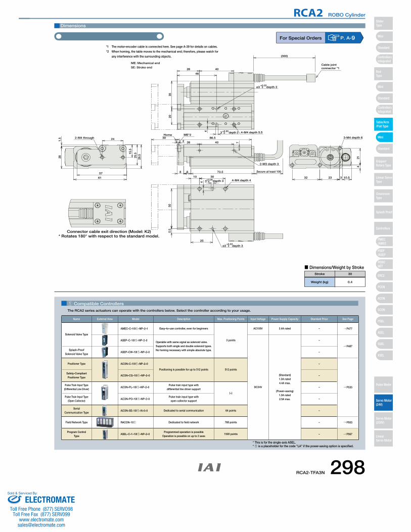
RCA2-TFA3N 298
RCA2 ROBO Cylinder
302
73.588
86.5ME*2Home
242-M4 through
15.5
29.5
1.5
57
61
25.5
28
32 23
214
3 10.5
3-M4 depth 6
4
4026
46
20
4-M4 depth 5.5
ø3 0+0.03
depth 3
3 0+0.05depth 3
35
4
25
505.
5
30104-M4 depth 4
ø3 0+0.03
depth 3
3 0+0.05depth 3
ME: Mechanical end
Secure at least 100
(300)
Cable jointconnector *1
Connector cable exit direction (Model: K2)* Rotates 180° with respect to the standard model.
2-M3 depth 3
74026
SE: Stroke end
Dimensions
■ Dimensions/Weight by Stroke
Weight (kg)
Stroke
0.4
30
For Special Orders P. A-9*1 The motor-encoder cable is connected here. See page A-39 for details on cables.
*2 When homing, the table moves to the mechanical end; therefore, please watch for
any interference with the surrounding objects.
1 Compatible Controllers
The RCA2 series actuators can operate with the controllers below. Select the controller according to your usage.
* This is for the single-axis ASEL.* 1 is a placeholder for the code "LA" if the power-saving option is specified.
Name External View Model Description Max. Positioning Points Input Voltage Power Supply Capacity Standard Price See Page
Solenoid Valve Type
AMEC–C–10I1–NP–2–1 Easy–to–use controller, even for beginners
3 points
AC100V 2.4A rated – → P477
ASEP–C–10I1–NP–2–0Operable with same signal as solenoid valve.Supports both single and double solenoid types.No homing necessary with simple absolute type.
DC24V
(Standard)1.3A rated4.4A max.
(Power–saving)1.3A rated2.5A max.
–
→ P487Splash–Proof
Solenoid Valve TypeASEP–CW–10I1–NP–2–0 –
Positioner Type ACON–C–10I1–NP–2–0
Positioning is possible for up to 512 points 512 points
–
→ P535
Safety–Compliant Positioner Type
ACON–CG–10I1–NP–2–0 –
Pulse Train Input Type(Differential Line Driver)
ACON–PL–10I1–NP–2–0Pulse train input type with
differential line driver support(−)
–
Pulse Train Input Type(Open Collector)
ACON–PO–10I1–NP–2–0Pulse train input type with
open collector support–
Serial Communication Type
ACON–SE–10I1–N–0–0 Dedicated to serial communication 64 points –
Field Network Type RACON–101 Dedicated to field network 768 points – → P503
Program Control Type
ASEL–C–1–10I1–NP–2–0Programmed operation is possible
Operation is possible on up to 2 axes1500 points – → P567
Mini
Mini
PSEP/ASEP
PMEC/AMEC
ROBONET
ERC2
PCON
ACON
SCON
PSEL
ASEL
SSEL
XSEL
Standard
Mini
Standard
Standard
ControllersIntegrated
ControllersIntegrated
SliderType
RodType
Table/Arm/Flat Type
Gripper/Rotary Type
Linear ServoType
Cleanroom Type
Splash Proof
Controllers
Pulse Motor
Servo Motor (24V)
Servo Motor (200V)
LinearServo Motor
ELECTROMATEToll Free Phone (877) SERVO98
Toll Free Fax (877) SERV099www.electromate.com
Sold & Serviced By:
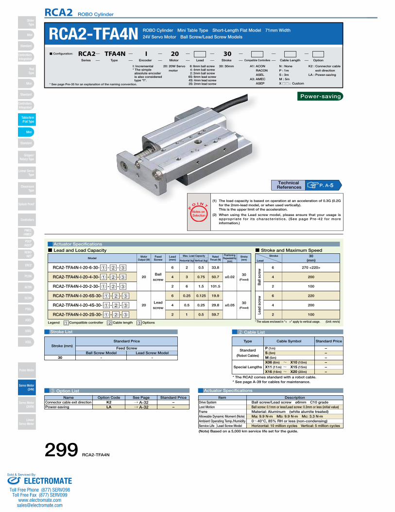
299 RCA2-TFA4N
RCA2 ROBO Cylinder
* The values enclosed in "< >" apply to vertical usage.
Bal
l scr
ewLe
ad s
crew
6
2
4
220
200
100
RCA2-TFA4N ROBO Cylinder Mini Table Type Short-Length Flat Model 71mm Width
24V Servo Motor Ball Screw/Lead Screw Models
* See page Pre-35 for an explanation of the naming convention.
20: 20W Servo motor
I: Incremental* The simple absolute encoder is also considered type "I".
A1: ACON RACON ASEL
A3: AMEC ASEP
N : NoneP : 1mS : 3mM : 5mX □□ : Custom
K2 : Connector cable exit direction
LA : Power-saving
30: 30mm6: 6mm ball screw4: 4mm ball screw2: 2mm ball screw
6S: 6mm lead screw4S: 4mm lead screw2S: 2mm lead screw
■ Configuration: RCA2 TFA4N I 20 30Series Type Encoder Motor Lead Stroke Compatible Controllers Cable Length Option
3 Option List
Stroke List 2 Cable List
Actuator Specifications
Legend 1 Compatible controller 2 Cable length 3 Options
Actuator Specifications
Stroke
Lead
30(mm)
270 <220>
200
100
6
4
2
■ Lead and Load Capacity ■ Stroke and Maximum Speed
P
O I N T
Notes on Selection
(Unit: mm/s)
Lead(mm)
Motor Output (W) Horizontal (kg) Vertical (kg)
Max. Load Capacity Positioning Repeatability
(mm)
Rated Thrust (N)Model Stroke
(mm)
RCA2-TFA4N-I-20-6-30- 1 - 2 - 3
RCA2-TFA4N-I-20-4-30- 1 - 2 - 3
RCA2-TFA4N-I-20-2-30- 1 - 2 - 3
20
26
34
62
0.5
0.75
1.5
33.8
50.7
101.5
30(Fixed)
±0.02
RCA2-TFA4N-I-20-6S-30- 1 - 2 - 3
RCA2-TFA4N-I-20-4S-30- 1 - 2 - 3
RCA2-TFA4N-I-20-2S-30- 1 - 2 - 3
20
0.256
0.54
12
0.125
0.25
0.5
19.9
29.8
59.7
30(Fixed)
±0.05
* The RCA2 comes standard with a robot cable.* See page A-39 for cables for maintenance.
Special Lengths
Type Standard PriceCable Symbol
Standard
(Robot Cables)
P (1m)
S (3m)
M (5m)
X06 (6m) ~ X10 (10m)
X11 (11m) ~ X15 (15m)
X16 (16m) ~ X20 (20m)
––––––
DescriptionItemBall screw/Lead screw ø6mm C10 grade Ball screw: 0.1mm or less/Lead screw: 0.3mm or less (initial value)Material: Aluminum (white alumite treated)Ma: 9.9 N∙m Mb: 9.9 N∙m Mc: 3.3 N∙m0~40°C, 85% RH or less (non-condensing)Horizontal: 10 million cycles Vertical: 5 million cycles
Drive SystemLost MotionFrameAllowable Dynamic Moment (Note)Ambient Operating Temp./HumidityService Life Lead Screw Model
(1) The load capacity is based on operation at an acceleration of 0.3G (0.2G for the 2mm-lead model, or when used vertically).This is the upper limit of the acceleration.
(2) When using the Lead screw model, please ensure that your usage is appropriate for its characteristics. (See page Pre-42 for more information.)
Ball
screw
Lead
screw
Feed Screw
(Note) Based on a 5,000 km service life set for the guide.
Name Standard PriceOption Code See PageK2LA
→ A-32→ A-32
Connector cable exit directionPower-saving
––
P. A-5Technical References
- -
Feed ScrewBall Screw Model Lead Screw Model
30
Stroke (mm)Standard Price
Power-saving
Mini
Mini
PSEP/ASEP
PMEC/AMEC
ROBONET
ERC2
PCON
ACON
SCON
PSEL
ASEL
SSEL
XSEL
Standard
Mini
Standard
Standard
ControllersIntegrated
ControllersIntegrated
RodType
Table/Arm/Flat Type
Gripper/Rotary Type
Linear ServoType
Cleanroom Type
Splash Proof
Controllers
Pulse Motor
Servo Motor (24V)
Servo Motor (200V)
LinearServo Motor
SliderType
ELECTROMATEToll Free Phone (877) SERVO98
Toll Free Fax (877) SERV099www.electromate.com
Sold & Serviced By:
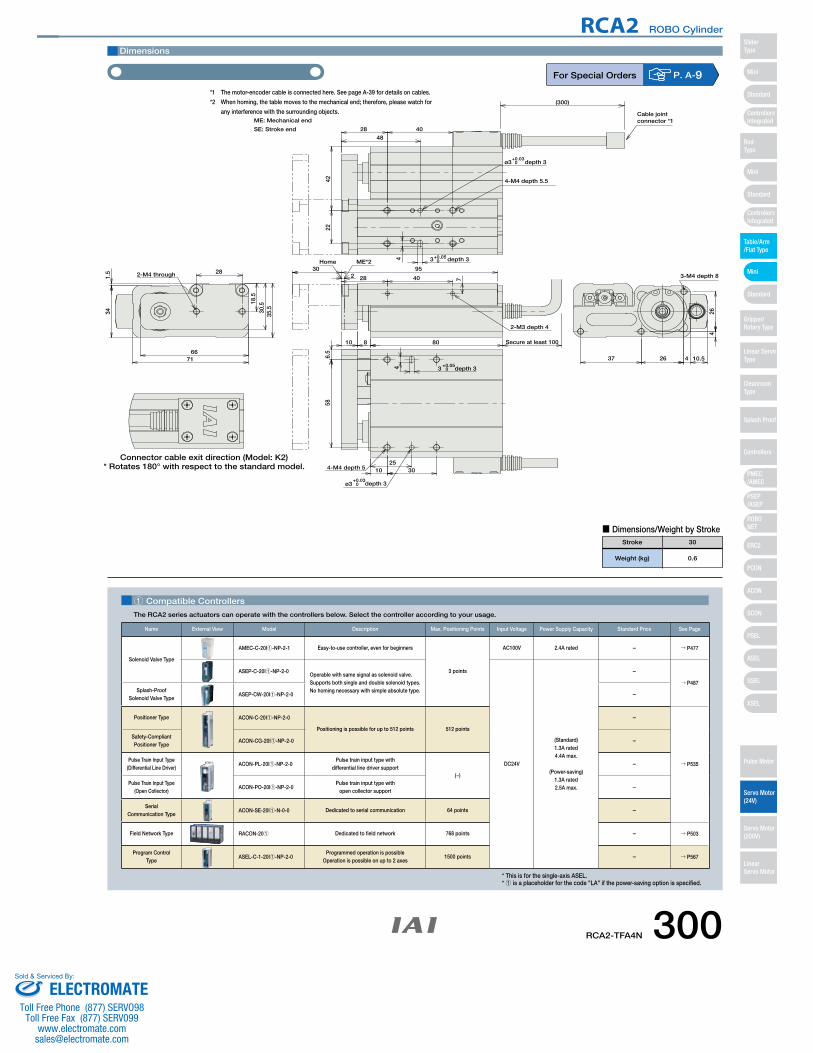
RCA2-TFA4N 300
RCA2 ROBO Cylinder
302
95
80810
Home ME*2
28
18.5
35.5
1.5 2-M4 through
7166
34 30.5
37 26
264
4 10.5
3-M4 depth 8
4
22
4028
48
4-M4 depth 5.5
ø3 0+0.03
depth 3
3 0+0.05 depth 3
42
4
58
3010
6.5
4-M4 depth 5
ø3 0+0.03
depth 3
3 0+0.05
depth 3
25
Secure at least 100
ME: Mechanical end
(300)
Connector cable exit direction (Model: K2)* Rotates 180° with respect to the standard model.
Cable jointconnector *1
2-M3 depth 4
28 740
SE: Stroke end
Dimensions
■ Dimensions/Weight by Stroke
Weight (kg)
Stroke
0.6
30
For Special Orders P. A-9*1 The motor-encoder cable is connected here. See page A-39 for details on cables.
*2 When homing, the table moves to the mechanical end; therefore, please watch for
any interference with the surrounding objects.
1 Compatible Controllers
The RCA2 series actuators can operate with the controllers below. Select the controller according to your usage.
* This is for the single-axis ASEL.* 1 is a placeholder for the code "LA" if the power-saving option is specified.
Name External View Model Description Max. Positioning Points Input Voltage Power Supply Capacity Standard Price See Page
Solenoid Valve Type
AMEC-C-20I1-NP-2-1 Easy-to-use controller, even for beginners
3 points
AC100V 2.4A rated – → P477
ASEP-C-20I1-NP-2-0Operable with same signal as solenoid valve.Supports both single and double solenoid types.No homing necessary with simple absolute type.
DC24V
(Standard)1.3A rated4.4A max.
(Power-saving)1.3A rated2.5A max.
–
→ P487Splash-Proof
Solenoid Valve TypeASEP-CW-20I1-NP-2-0 –
Positioner Type ACON-C-20I1-NP-2-0
Positioning is possible for up to 512 points 512 points
–
→ P535
Safety-Compliant Positioner Type
ACON-CG-20I1-NP-2-0 –
Pulse Train Input Type(Differential Line Driver)
ACON-PL-20I1-NP-2-0Pulse train input type with
differential line driver support(−)
–
Pulse Train Input Type(Open Collector)
ACON-PO-20I1-NP-2-0Pulse train input type with
open collector support–
Serial Communication Type
ACON-SE-20I1-N-0-0 Dedicated to serial communication 64 points –
Field Network Type RACON-201 Dedicated to field network 768 points – → P503
Program Control Type
ASEL-C-1-20I1-NP-2-0Programmed operation is possible
Operation is possible on up to 2 axes1500 points – → P567
Mini
Mini
PSEP/ASEP
PMEC/AMEC
ROBONET
ERC2
PCON
ACON
SCON
PSEL
ASEL
SSEL
XSEL
Standard
Mini
Standard
Standard
ControllersIntegrated
ControllersIntegrated
SliderType
RodType
Table/Arm/Flat Type
Gripper/Rotary Type
Linear ServoType
Cleanroom Type
Splash Proof
Controllers
Pulse Motor
Servo Motor (24V)
Servo Motor (200V)
LinearServo Motor
ELECTROMATEToll Free Phone (877) SERVO98
Toll Free Fax (877) SERV099www.electromate.com
Sold & Serviced By:
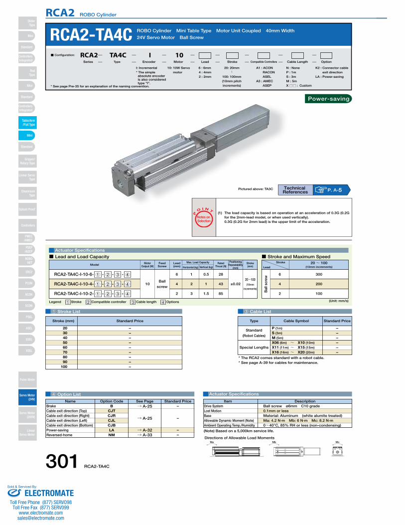
Bal
l scr
ewMotor
Output (W)
Positioning Repeatability
(mm)
Rated Thrust (N)Model Stroke
(mm)
RCA2-TA4C-I-10-6- 1 - 2 - 3 - 4
RCA2-TA4C-I-10-4- 1 - 2 - 3 - 4
RCA2-TA4C-I-10-2- 1 - 2 - 3 - 4
10Ball
screw
16
24
32
0.5
1
1.5
28
43
85
20~100(10mm
increments)
±0.02
Horizontal (kg) Vertical (kg)
Max. Load CapacityLead(mm)
Feed Screw
1 Stroke List 3 Cable List
4 Option List Actuator Specifications
RCA2-TA4C ROBO Cylinder Mini Table Type Motor Unit Coupled 40mm Width
24V Servo Motor Ball Screw
Legend 1 Stroke 2 Compatible controller 3 Cable length 4 Options
Actuator Specifications
Stroke
Lead20~ 100
(10mm increments)
300
200
100
6
4
2
■ Lead and Load Capacity ■ Stroke and Maximum Speed
P
O I N T
Notes on Selection
(1) The load capacity is based on operation at an acceleration of 0.3G (0.2G for the 2mm-lead model, or when used vertically).0.3G (0.2G for 2mm lead) is the upper limit of the acceleration.
(Unit: mm/s)
* See page Pre-35 for an explanation of the naming convention.
10: 10W Servo motor
I: Incremental* The simple absolute encoder is also considered type "I".
N : NoneP : 1mS : 3mM : 5mX □□ : Custom
K2 : Connector cable exit direction
LA : Power-saving
6 : 6mm4 : 4mm2 : 2mm
■ Configuration: RCA2 TA4C I 10Series Type Encoder Motor Lead Stroke Compatible Controllers Cable Length Option
Special Lengths
Type Standard PriceCable Symbol
Standard
(Robot Cables)
P (1m)
S (3m)
M (5m)
X06 (6m) ~ X10 (10m)
X11 (11m) ~ X15 (15m)
X16 (16m) ~ X20 (20m)
––––––
–––––––––
2030405060708090
100
DescriptionItemBall screw ø6mm C10 grade 0.1mm or lessMaterial: Aluminum (white alumite treated)Ma: 4.2 N∙m Mb: 6 N∙m Mc: 8.2 N∙m0~40°C, 85% RH or less (non-condensing)
Drive SystemLost MotionBaseAllowable Dynamic Moment (Note)Ambient Operating Temp./Humidity
* The RCA2 comes standard with a robot cable.* See page A-39 for cables for maintenance.
(Note) Based on a 5,000km service life.
A1 : ACON RACON ASEL
A3 : AMEC ASEP
Pictured above: TA3C
Name Standard PriceOption Code See PageB
CJTCJRCJLCJBLANM
BrakeCable exit direction (Top)Cable exit direction (Right)Cable exit direction (Left)Cable exit direction (Bottom)Power-savingReversed-home
20: 20mm〜
100: 100mm(10mm pitch increments)
Technical References P. A-5
Stroke (mm) Standard Price
→ A-25
→ A-32→ A-33
–
––
→ A-25 –
Ma Mb Mc
Directions of Allowable Load Moments
Power-saving
301 RCA2-TA4C
RCA2 ROBO Cylinder
Mini
Mini
PSEP/ASEP
PMEC/AMEC
ROBONET
ERC2
PCON
ACON
SCON
PSEL
ASEL
SSEL
XSEL
Standard
Mini
Standard
Standard
ControllersIntegrated
ControllersIntegrated
RodType
Table/Arm/Flat Type
Gripper/Rotary Type
Linear ServoType
Cleanroom Type
Splash Proof
Controllers
Pulse Motor
Servo Motor (24V)
Servo Motor (200V)
LinearServo Motor
SliderType
ELECTROMATEToll Free Phone (877) SERVO98
Toll Free Fax (877) SERV099www.electromate.com
Sold & Serviced By:
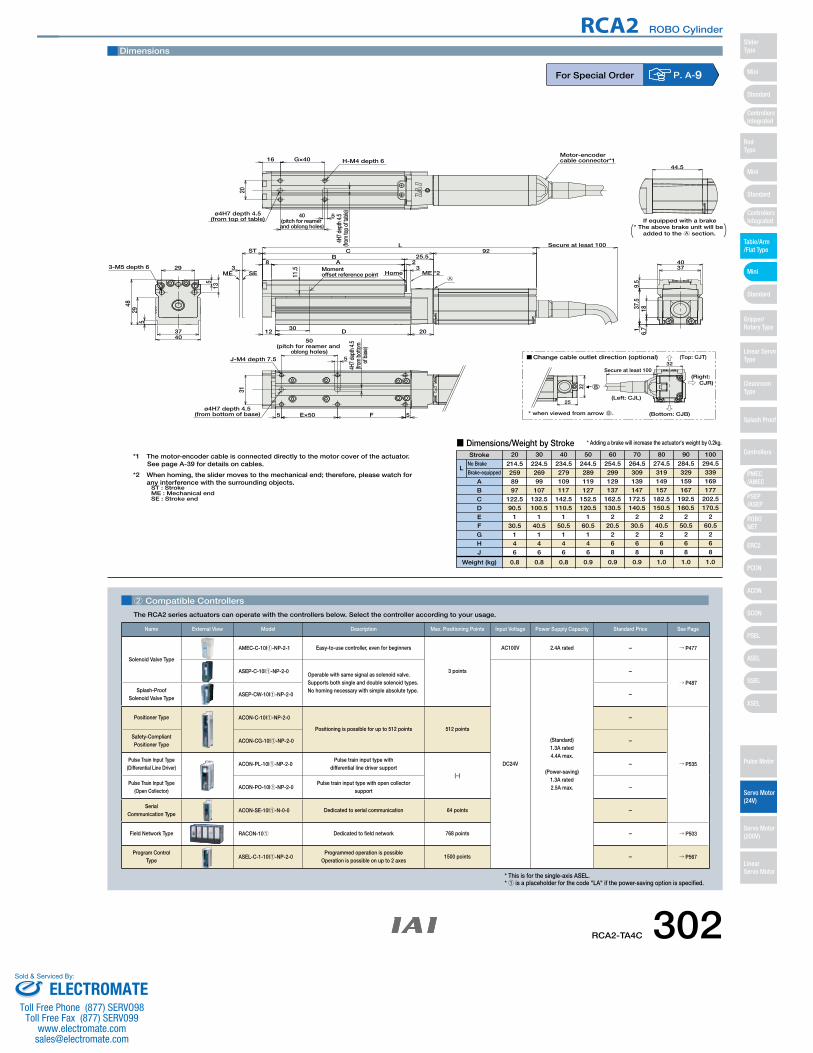
CAD drawings can bedownloaded from IAI website.
20
5
4H7 d
epth
4.5
(from
bot
tom
of
bas
e)
F
3-M5 depth 6 29
ST
8 AB
CL
25.592
Secure at least 100
23
ME *2Home3
4037
513
529
48
D12
4037
9.5
37.5
16.
718
If equipped with a brakeø4H7 depth 4.5
(from top of table)40
(pitch for reamer and oblong holes)
20
4H7 d
epth
4.5
(from
top
of ta
ble)
5
16 G×40 H-M4 depth 644.5
5
50(pitch for reamer and
oblong holes)J-M4 depth 7.5
31
ø4H7 depth 4.5(from bottom of base) 5 E×50
Motor-encodercable connector*1
SEME
ST : Stroke
* The above brake unit will be added to the A section.
A
Momentoffset reference point11
.5
30
Secure at least 100
(Left: CJL)
(Top: CJT)
(Bottom: CJB)* when viewed from arrow B.
(Right: CJR)
Change cable outlet direction (optional)
B
25
32
32
ME : Mechanical endSE : Stroke end
*1 The motor-encoder cable is connected directly to the motor cover of the actuator.See page A-39 for details on cables.
*2 When homing, the slider moves to the mechanical end; therefore, please watch for any interference with the surrounding objects.
Dimensions
■ Dimensions/Weight by StrokeStroke
LNo Brake
Brake-equipped
ABCDEFGHJ
Weight (kg)
214.52598997
122.590.5
130.5
146
0.8
224.526999107
132.5100.5
140.5
146
0.8
234.5279109117
142.5110.5
150.5
146
0.8
244.5289119127
152.5120.5
160.5
146
0.9
254.5299129137
162.5130.5
220.5
268
0.9
264.5309139147
172.5140.5
230.5
268
0.9
274.5319149157
182.5150.5
240.5
268
1.0
284.5329159167
192.5160.5
250.5
268
1.0
294.5339169177
202.5170.5
260.5
268
1.0
20 30 40 50 60 70 80 90 100
* Adding a brake will increase the actuator's weight by 0.2kg.
For Special Order P. A-9
2 Compatible Controllers
The RCA2 series actuators can operate with the controllers below. Select the controller according to your usage.
* This is for the single-axis ASEL.* 1 is a placeholder for the code "LA" if the power-saving option is specified.
Name External View Model Description Max. Positioning Points Input Voltage Power Supply Capacity Standard Price See Page
Solenoid Valve Type
AMEC-C-10I1-NP-2-1 Easy-to-use controller, even for beginners
3 points
AC100V 2.4A rated – → P477
ASEP-C-10I1-NP-2-0Operable with same signal as solenoid valve.Supports both single and double solenoid types.No homing necessary with simple absolute type.
DC24V
(Standard)1.3A rated4.4A max.
(Power-saving)1.3A rated2.5A max.
–
→ P487Splash-Proof
Solenoid Valve TypeASEP-CW-10I1-NP-2-0 –
Positioner Type ACON-C-10I1-NP-2-0
Positioning is possible for up to 512 points 512 points
–
→ P535
Safety-Compliant Positioner Type
ACON-CG-10I1-NP-2-0 –
Pulse Train Input Type(Differential Line Driver)
ACON-PL-10I1-NP-2-0Pulse train input type with
differential line driver support(−)
–
Pulse Train Input Type(Open Collector)
ACON-PO-10I1-NP-2-0Pulse train input type with open collector
support–
Serial Communication Type
ACON-SE-10I1-N-0-0 Dedicated to serial communication 64 points –
Field Network Type RACON-101 Dedicated to field network 768 points – → P503
Program Control Type
ASEL-C-1-10I1-NP-2-0Programmed operation is possible
Operation is possible on up to 2 axes1500 points – → P567
RCA2-TA4C 302
RCA2 ROBO Cylinder
Mini
Mini
PSEP/ASEP
PMEC/AMEC
ROBONET
ERC2
PCON
ACON
SCON
PSEL
ASEL
SSEL
XSEL
Standard
Mini
Standard
Standard
ControllersIntegrated
ControllersIntegrated
SliderType
RodType
Table/Arm/Flat Type
Gripper/Rotary Type
Linear ServoType
Cleanroom Type
Splash Proof
Controllers
Pulse Motor
Servo Motor (24V)
Servo Motor (200V)
LinearServo Motor
ELECTROMATEToll Free Phone (877) SERVO98
Toll Free Fax (877) SERV099www.electromate.com
Sold & Serviced By:

(*) Based on a 5,000km service life.
* The RCA2 comes standard with a robot cable.
* See page A-39 for cables for maintenance.
Special Lengths
Type Standard PriceCable Symbol
Standard Type
(Robot Cables)
P (1m)
S (3m)
M (5m)
X06 (6m) ~ X10 (10m)
X11 (11m) ~ X15 (15m)
X16 (16m) ~ X20 (20m)
– – – – – –
3 Cable List
4 Options List Actuator Specifications
RCA2-TA5C ROBO Cylinder Table Type Motor Unit Coupled 55mm Width 24V Servo Motor
Ball Screw
Actuator Specifications
■ Lead and Load Capacity ■ Stroke and Maximum Speed
P
O I N T
Notes on Selection
(1) Please note that the maximum speed is different when used horizontally versus vertically.
(2) The load capacity is based on operation at an acceleration of 0.3G (0.2G for the 2.5mm-lead model, or when used vertically). This is the upper limit of the acceleration.
Legend: 1 Stroke 2 Compatible controller 3 Cable length 4 Options (Unit: mm/s)
1 Stroke List
* See page Pre-35 for an explanation of the naming convention.
Ma Mb Mc
Directions of Allowable Load Moments
DescriptionItemBall screw ø8mm C10 grade±0.02mm0.1mm or lessMaterial: Aluminum (special alumite treated)Ma: 25.5 N∙m Mb: 36.5 N∙m Mc: 56.1 N∙mMa: 6.57 N∙m Mb: 9.32 N∙m Mc: 14.32 N∙mWithin the load moment range0~40°C, 85% RH or less (non-condensing)
Drive SystemPositioning RepeatabilityLost MotionBaseAllowable Static MomentAllowable Dynamic Moment (*)Overhang Load LengthAmbient Operating Temp./Humidity
20: 20W Servo motor
I: Incremental* The simple absolute encoder is also considered type "I".
A1: ACON RACON ASEL
A3: AMEC ASEP
N : NoneP : 1mS : 3mM : 5mX □□ : Custom
See Options below25: 25mm〜
100: 100mm(25mm pitch increments)
10 : 10mm5 : 5mm
2.5 : 2.5mm
■ Configuration: RCA2 TA5C I 20Series Type Encoder Motor Lead Stroke Compatible Controllers Cable Length Option
Stroke
Lead25~ 100
(25mm increments)
465 <400>
250
125
10
5
2.5
Motor Output (W)
Lead(mm) Horizontal (kg) Vertical (kg)
Max. Load Capacity Rated Thrust (N)
Model Stroke(mm)
RCA2-TA5C-I-20-10- 1 - 2 - 3 - 4
RCA2-TA5C-I-20-5- 1 - 2 - 3 - 4
RCA2-TA5C-I-20-2.5- 1 - 2 - 3 - 4
20
10
5
2.5
2
3.5
5
1
2
3
34
68
137
25~100(25mm
increments)
* The values enclosed in "< >" apply to vertical usage.
– – – –
255075
100
Technical References P. A-5
Name Option Code Standard Price Standard PriceBrake B → A-25 – Cable exit direction (Top) CJT → A-25 – Cable exit direction (Right) CJR → A-25 – Cable exit direction (Left) CJL → A-25 – Cable exit direction (Bottom) CJB → A-25 – Power-saving LA → A-32 – Reversed-home NM → A-33 –
Stroke (mm) Standard Price
Power-saving
303 RCA2-TA5C
RCA2 ROBO Cylinder
Mini
Mini
PSEP/ASEP
PMEC/AMEC
ROBONET
ERC2
PCON
ACON
SCON
PSEL
ASEL
SSEL
XSEL
Standard
Mini
Standard
Standard
ControllersIntegrated
ControllersIntegrated
RodType
Table/Arm/Flat Type
Gripper/Rotary Type
Linear ServoType
Cleanroom Type
Splash Proof
Controllers
Pulse Motor
Servo Motor (24V)
Servo Motor (200V)
LinearServo Motor
SliderType
ELECTROMATEToll Free Phone (877) SERVO98
Toll Free Fax (877) SERV099www.electromate.com
Sold & Serviced By:
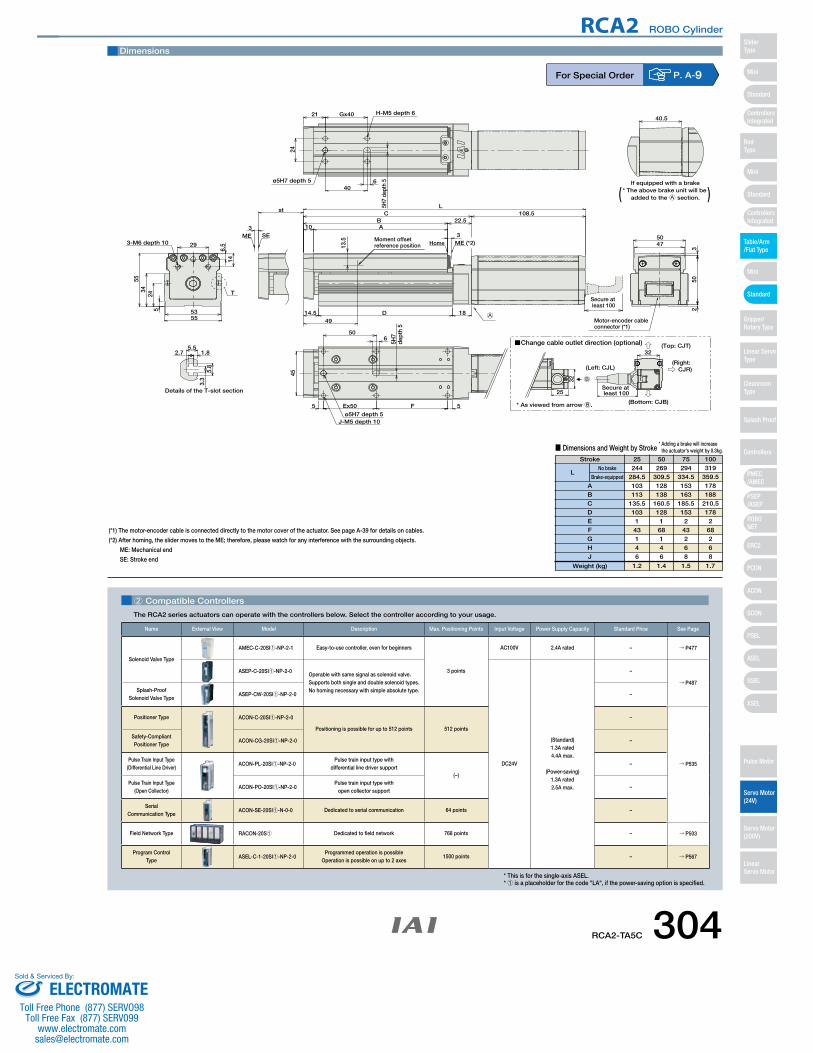
CAD drawings can bedownloaded from IAI website. www.intelligentactuator.com
Secure at least 100
ME SE3
st
T
* As viewed from arrow B.
Change cable outlet direction (optional)
(Left: CJL)
(Top: CJT)
(Bottom: CJB)
(Right: CJR)
Secure at least 100
B
25
32
32
If equipped with a brake
40.5
Details of the T-slot section
2.7 1.85.5
5.8
3.3
250
3
50473-M6 depth 10 29
146.
5
5534
245
5553
J-M5 depth 10ø5H7 depth 5
5H7
dept
h 5
45
5FEx505
650
ø5H7 depth 5
H-M5 depth 6
24
Gx4021
5H7
dept
h 56
40
Home ME (*2)
108.5C22.5
1814.5 D
L
BA10
3
Motor-encoder cableconnector (*1)
* The above brake unit will be added to the A section.( )
A
Moment offsetreference position13
.5
49
Dimensions
2 Compatible Controllers
The RCA2 series actuators can operate with the controllers below. Select the controller according to your usage.
For Special Order P. A-9
(*1) The motor-encoder cable is connected directly to the motor cover of the actuator. See page A-39 for details on cables.
(*2) After homing, the slider moves to the ME; therefore, please watch for any interference with the surrounding objects.
ME: Mechanical end
SE: Stroke end
* This is for the single-axis ASEL.* 1 is a placeholder for the code "LA", if the power-saving option is specified.
Stroke 25 50 75 100
■ Dimensions and Weight by Stroke
244284.5103113
135.5103
143146
269309.5128138
160.5128
168146
294334.5153163
185.5153
243268
319359.5178188
210.5178
268268
1.2 1.4 1.5 1.7
ABCDEFGHJ
LNo brake
Brake-equipped
Weight (kg)
* Adding a brake will increase the actuator's weight by 0.3kg.
Name External View Model Description Max. Positioning Points Input Voltage Power Supply Capacity Standard Price See Page
Solenoid Valve Type
AMEC-C-20SI1-NP-2-1 Easy-to-use controller, even for beginners
3 points
AC100V 2.4A rated – → P477
ASEP-C-20SI1-NP-2-0Operable with same signal as solenoid valve.Supports both single and double solenoid types.No homing necessary with simple absolute type.
DC24V
(Standard)1.3A rated4.4A max.
(Power-saving)1.3A rated2.5A max.
–
→ P487Splash-Proof
Solenoid Valve TypeASEP-CW-20SI1-NP-2-0 –
Positioner Type ACON-C-20SI1-NP-2-0
Positioning is possible for up to 512 points 512 points
–
→ P535
Safety-Compliant Positioner Type
ACON-CG-20SI1-NP-2-0 –
Pulse Train Input Type(Differential Line Driver)
ACON-PL-20SI1-NP-2-0Pulse train input type with
differential line driver support(−)
–
Pulse Train Input Type(Open Collector)
ACON-PO-20SI1-NP-2-0Pulse train input type with
open collector support–
Serial Communication Type
ACON-SE-20SI1-N-0-0 Dedicated to serial communication 64 points –
Field Network Type RACON-20S1 Dedicated to field network 768 points – → P503
Program Control Type
ASEL-C-1-20SI1-NP-2-0Programmed operation is possible
Operation is possible on up to 2 axes1500 points – → P567
RCA2-TA5C 304
RCA2 ROBO Cylinder
Mini
Mini
PSEP/ASEP
PMEC/AMEC
ROBONET
ERC2
PCON
ACON
SCON
PSEL
ASEL
SSEL
XSEL
Standard
Mini
Standard
Standard
ControllersIntegrated
ControllersIntegrated
SliderType
RodType
Table/Arm/Flat Type
Gripper/Rotary Type
Linear ServoType
Cleanroom Type
Splash Proof
Controllers
Pulse Motor
Servo Motor (24V)
Servo Motor (200V)
LinearServo Motor
ELECTROMATEToll Free Phone (877) SERVO98
Toll Free Fax (877) SERV099www.electromate.com
Sold & Serviced By:
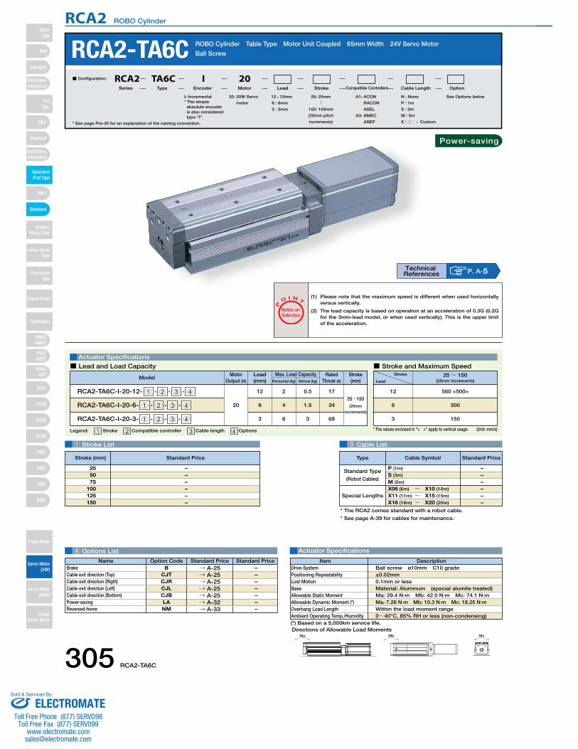
(*) Based on a 5,000km service life.
* The RCA2 comes standard with a robot cable.
* See page A-39 for cables for maintenance.
Special Lengths
Type Standard PriceCable Symbol
Standard Type
(Robot Cables)
P (1m)
S (3m)
M (5m)
X06 (6m) ~ X10 (10m)
X11 (11m) ~ X15 (15m)
X16 (16m) ~ X20 (20m)
– – – – – –
3 Cable List
4 Options List Actuator Specifications
RCA2-TA6C ROBO Cylinder Table Type Motor Unit Coupled 65mm Width 24V Servo Motor
Ball Screw
Actuator Specifications
■ Lead and Load Capacity ■ Stroke and Maximum Speed
P
O I N T
Notes on Selection
(1) Please note that the maximum speed is different when used horizontally versus vertically.
(2) The load capacity is based on operation at an acceleration of 0.3G (0.2G for the 3mm-lead model, or when used vertically). This is the upper limit of the acceleration.
Legend: 1 Stroke 2 Compatible controller 3 Cable length 4 Options (Unit: mm/s)
1 Stroke List
* See page Pre-35 for an explanation of the naming convention.
Technical References P. A-5
Ma Mb Mc
Directions of Allowable Load Moments
DescriptionItemBall screw ø10mm C10 grade±0.02mm0.1mm or lessMaterial: Aluminum (special alumite treated)Ma: 29.4 N∙m Mb: 42.0 N∙m Mc: 74.1 N∙mMa: 7.26 N∙m Mb: 10.3 N∙m Mc: 18.25 N∙mWithin the load moment range0~40°C, 85% RH or less (non-condensing)
Drive SystemPositioning RepeatabilityLost MotionBaseAllowable Static MomentAllowable Dynamic Moment (*)Overhang Load LengthAmbient Operating Temp./Humidity
Stroke
Lead25~ 150
(25mm increments)
560 <500>
300
150
12
6
3
Motor Output (W)
Lead(mm) Horizontal (kg) Vertical (kg)
Max. Load Capacity Rated Thrust (N)
ModelStroke(mm)
RCA2-TA6C-I-20-12- 1 - 2 - 3 - 4
RCA2-TA6C-I-20-6- 1 - 2 - 3 - 4
RCA2-TA6C-I-20-3- 1 - 2 - 3 - 4
20
12
6
3
2
4
6
0.5
1.5
3
17
34
68
25~150(25mm
increments)
* The values enclosed in "< >" apply to vertical usage.
20: 20W Servo
motor
I: Incremental* The simple
absolute encoder is also considered type "I".
A1: ACON
RACON
ASEL
A3: AMEC
ASEP
N : None
P : 1m
S : 3m
M : 5m
X □□ : Custom
See Options below25: 25mm
〜150: 150mm
(25mm pitch
increments)
12 : 12mm
6 : 6mm
3 : 3mm
■ Configuration: RCA2 TA6C I 20Series Type Encoder Motor Lead Stroke Compatible Controllers Cable Length Option
– – – – – –
255075
100125150
Name Option Code Standard Price Standard PriceBrake B → A-25 – Cable exit direction (Top) CJT → A-25 – Cable exit direction (Right) CJR → A-25 – Cable exit direction (Left) CJL → A-25 – Cable exit direction (Bottom) CJB → A-25 – Power-saving LA → A-32 – Reversed-home NM → A-33 –
Stroke (mm) Standard Price
Power-saving
305 RCA2-TA6C
RCA2 ROBO Cylinder
Mini
Mini
PSEP/ASEP
PMEC/AMEC
ROBONET
ERC2
PCON
ACON
SCON
PSEL
ASEL
SSEL
XSEL
Standard
Mini
Standard
Standard
ControllersIntegrated
ControllersIntegrated
RodType
Table/Arm/Flat Type
Gripper/Rotary Type
Linear ServoType
Cleanroom Type
Splash Proof
Controllers
Pulse Motor
Servo Motor (24V)
Servo Motor (200V)
LinearServo Motor
SliderType
ELECTROMATEToll Free Phone (877) SERVO98
Toll Free Fax (877) SERV099www.electromate.com
Sold & Serviced By:
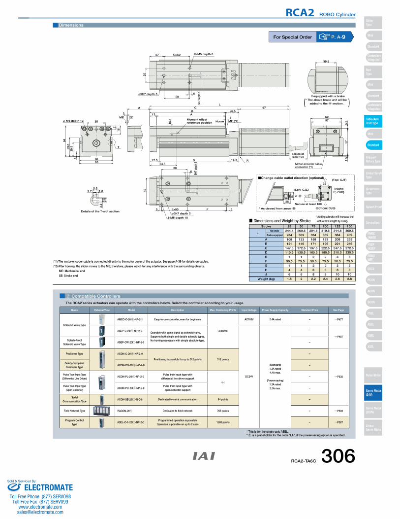
CAD drawings can bedownloaded from IAI website. www.intelligentactuator.com
Dimensions
2 Compatible Controllers
The RCA2 series actuators can operate with the controllers below. Select the controller according to your usage.
For Special Order P. A-9
(*1) The motor-encoder cable is connected directly to the motor cover of the actuator. See page A-39 for details on cables.
(*2) After homing, the slider moves to the ME; therefore, please watch for any interference with the surrounding objects.
ME: Mechanical end
SE: Stroke end
Stroke 25 50 75 100 125 150
■ Dimensions and Weight by Stroke
244.5284108121
147.5110.5
150.5
146
269.5309133146
172.5135.5
175.5
146
294.5334158171
197.5160.5
250.5
268
319.5359183196
222.5185.5
275.5
268
344.5384208221
247.5210.5
350.5
3810
369.5409233246
272.5235.5
375.5
3810
1.8 2 2.2 2.4 2.6 2.8
ABCDEFGHJ
LNo brake
Brake-equipped
Weight (kg)
* Adding a brake will increase the actuator's weight by 0.4kg.
* This is for the single-axis ASEL.* 1 is a placeholder for the code "LA", if the power-saving option is specified.
Name External View Model Description Max. Positioning Points Input Voltage Power Supply Capacity Standard Price See Page
Solenoid Valve Type
AMEC-C-20I1-NP-2-1 Easy-to-use controller, even for beginners
3 points
AC100V 2.4A rated – → P477
ASEP-C-20I1-NP-2-0Operable with same signal as solenoid valve.Supports both single and double solenoid types.No homing necessary with simple absolute type.
DC24V
(Standard)1.3A rated4.4A max.
(Power-saving)1.3A rated2.5A max.
–
→ P487Splash-Proof
Solenoid Valve TypeASEP-CW-20I1-NP-2-0 –
Positioner Type ACON-C-20I1-NP-2-0
Positioning is possible for up to 512 points 512 points
–
→ P535
Safety-Compliant Positioner Type
ACON-CG-20I1-NP-2-0 –
Pulse Train Input Type(Differential Line Driver)
ACON-PL-20I1-NP-2-0Pulse train input type with
differential line driver support(−)
–
Pulse Train Input Type(Open Collector)
ACON-PO-20I1-NP-2-0Pulse train input type with
open collector support–
Serial Communication Type
ACON-SE-20I1-N-0-0 Dedicated to serial communication 64 points –
Field Network Type RACON-201 Dedicated to field network 768 points – → P503
Program Control Type
ASEL-C-1-20I1-NP-2-0Programmed operation is possible
Operation is possible on up to 2 axes1500 points – → P567
Secure at least 100
ME SE3
st
T
* As viewed from arrow B.
Change cable outlet direction (optional)
(Left: CJL)
(Top: CJT)
(Bottom: CJB)
(Right: CJR)
B
Secure at least 10025
32
32
Details of the T-slot section
5.52.7 1.8
5.8
3.3
If equipped with a brake
39.5
571.
55.
5
60573-M6 depth 13
6439
.529
.55
3518
7
6563
J-M5 depth 10
ø5H7 depth 5
5H7
dept
h 5
6
5FEx505
55
50
ø5H7 depth 5
H-M5 depth 8
5H7
dept
h 56
Gx5027
30
50
19.5
97C26.5
L
17.5 D
BA13
3Home ME (*2)
Motor-encoder cableconnector (*1)
* The above brake unit will be added to the A section.( )
A
Moment offsetreference position15
.5
54.5
RCA2-TA6C 306
RCA2 ROBO Cylinder
Mini
Mini
PSEP/ASEP
PMEC/AMEC
ROBONET
ERC2
PCON
ACON
SCON
PSEL
ASEL
SSEL
XSEL
Standard
Mini
Standard
Standard
ControllersIntegrated
ControllersIntegrated
SliderType
RodType
Table/Arm/Flat Type
Gripper/Rotary Type
Linear ServoType
Cleanroom Type
Splash Proof
Controllers
Pulse Motor
Servo Motor (24V)
Servo Motor (200V)
LinearServo Motor
ELECTROMATEToll Free Phone (877) SERVO98
Toll Free Fax (877) SERV099www.electromate.com
Sold & Serviced By:
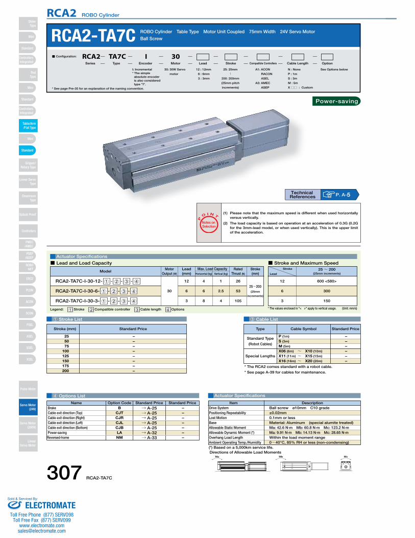
(*) Based on a 5,000km service life.
* The RCA2 comes standard with a robot cable.
* See page A-39 for cables for maintenance.
Special Lengths
Type Standard PriceCable Symbol
Standard Type
(Robot Cables)
P (1m)
S (3m)
M (5m)
X06 (6m) ~ X10 (10m)
X11 (11m) ~ X15 (15m)
X16 (16m) ~ X20 (20m)
– – – – – –
3 Cable List
4 Options List Actuator Specifications
RCA2-TA7C ROBO Cylinder Table Type Motor Unit Coupled 75mm Width 24V Servo Motor
Ball Screw
Actuator Specifications
■ Lead and Load Capacity ■ Stroke and Maximum Speed
P
O I N T
Notes on Selection
(1) Please note that the maximum speed is different when used horizontally versus vertically.
(2) The load capacity is based on operation at an acceleration of 0.3G (0.2G for the 3mm-lead model, or when used vertically). This is the upper limit of the acceleration.
Legend: 1 Stroke 2 Compatible controller 3 Cable length 4 Options (Unit: mm/s)
1 Stroke List
* See page Pre-35 for an explanation of the naming convention.
Ma Mb Mc
Directions of Allowable Load Moments
DescriptionItemBall screw ø10mm C10 grade±0.02mm0.1mm or lessMaterial: Aluminum (special alumite treated)Ma: 42.6 N∙m Mb: 60.8 N∙m Mc: 123.2 N∙mMa: 9.91 N∙m Mb: 14.13 N∙m Mc: 28.65 N∙mWithin the load moment range0~40°C, 85% RH or less (non-condensing)
Drive SystemPositioning RepeatabilityLost MotionBaseAllowable Static MomentAllowable Dynamic Moment (*)Overhang Load LengthAmbient Operating Temp./Humidity
Stroke
Lead25~ 200
(25mm increments)
600 <580>
300
150
12
6
3
Motor Output (W)
Lead(mm) Horizontal (kg) Vertical (kg)
Max. Load Capacity Rated Thrust (N)
ModelStroke(mm)
RCA2-TA7C-I-30-12- 1 - 2 - 3 - 4
RCA2-TA7C-I-30-6- 1 - 2 - 3 - 4
RCA2-TA7C-I-30-3- 1 - 2 - 3 - 4
30
12
6
3
4
6
8
1
2.5
4
26
53
105
25~200(25mm
increments)
* The values enclosed in "< >" apply to vertical usage.
Technical References P. A-5
30: 30W Servo
motor
I: Incremental* The simple
absolute encoder is also considered type "I".
A1: ACON
RACON
ASEL
A3: AMEC
ASEP
N : None
P : 1m
S : 3m
M : 5m
X □□ : Custom
See Options below25: 25mm
〜200: 200mm
(25mm pitch
increments)
12 : 12mm
6 : 6mm
3 : 3mm
■ Configuration: RCA2 TA7C I 30Series Type Encoder Motor Lead Stroke Compatible Controllers Cable Length Option
– – – – – – – –
255075
100125150175200
Name Option Code Standard Price Standard PriceBrake B → A-25 – Cable exit direction (Top) CJT → A-25 – Cable exit direction (Right) CJR → A-25 – Cable exit direction (Left) CJL → A-25 – Cable exit direction (Bottom) CJB → A-25 – Power-saving LA → A-32 –
Reversed-home NM → A-33 –
Stroke (mm) Standard Price
Power-saving
307 RCA2-TA7C
RCA2 ROBO Cylinder
Mini
Mini
PSEP/ASEP
PMEC/AMEC
ROBONET
ERC2
PCON
ACON
SCON
PSEL
ASEL
SSEL
XSEL
Standard
Mini
Standard
Standard
ControllersIntegrated
ControllersIntegrated
RodType
Table/Arm/Flat Type
Gripper/Rotary Type
Linear ServoType
Cleanroom Type
Splash Proof
Controllers
Pulse Motor
Servo Motor (24V)
Servo Motor (200V)
LinearServo Motor
SliderType
ELECTROMATEToll Free Phone (877) SERVO98
Toll Free Fax (877) SERV099www.electromate.com
Sold & Serviced By:
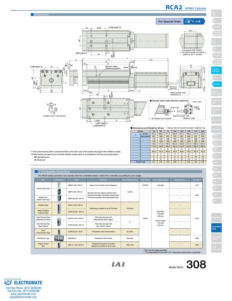
CAD drawings can bedownloaded from IAI website. www.intelligentactuator.com
Secure at least 100
* The above brake unit will be added to the A section.( )
* As viewed from arrow B.
Change cable outlet direction (optional)
(Left: CJL)
(Top: CJT)
(Bottom: CJB)
(Right: CJR)
B
Secure at least 10025
32
32
ME SE3
st
T
39.5
5.52.7 1.8
5.8
3.3
1.5
577.
5
74713-M8 depth 15
21.5
6.5
44
6639
.529
.55
7573
Details of the T-slot section
J-M6 depth 12ø6H7 depth 6
FEx505
64
7
6H7
dept
h 6
50
H-M6 depth 10
ø6H7 depth 6
6H7
dept
h 67
Gx5030
36
50
Home ME (*2)
112C16.5
19.5
L
19.5
Moment offsetreference position17
.5
61.5D
BA15
3
Motor-encoder cableconnector (*1)
If equipped with a brake
A
5
Dimensions
2 Compatible Controllers
The RCA2 series actuators can operate with the controllers below. Select the controller according to your usage.
For Special Order P. A-9
(*1) The motor-encoder cable is connected directly to the motor cover of the actuator. See page A-39 for details on cables.
(*2) After homing, the slider moves to the ME; therefore, please watch for any interference with the surrounding objects.
ME: Mechanical end
SE: Stroke end
Stroke 25 50 75 100 125 150 175 200
■ Dimensions and Weight by Stroke
261.5301118133
149.5110.5
150.5
146
286.5326143158
174.5135.5
175.5
146
311.5351168183
199.5160.5
250.5
268
336.5376193208
224.5185.5
275.5
268
361.5401218233
249.5210.5
350.5
3810
386.5426243258
274.5235.5
375.5
3810
411.5451268283
299.5260.5
450.5
41012
436.5476293308
324.5285.5
475.5
41012
2.1 2.3 2.5 2.8 3 3.2 3.4 3.6
A
B
C
D
E
F
G
H
J
LNo brake
Brake-equipped
Weight (kg)
* Adding a brake will increase the actuator's weight by 0.4kg.
* This is for the single-axis ASEL.* 1 is a placeholder for the code "LA", if the power-saving option is specified.
Name External View Model Description Max. Positioning Points Input Voltage Power Supply Capacity Standard Price See Page
Solenoid Valve Type
AMEC-C-30I1-NP-2-1 Easy-to-use controller, even for beginners
3 points
AC100V 2.4A rated – → P477
ASEP-C-30I1-NP-2-0Operable with same signal as solenoid valve.Supports both single and double solenoid types.No homing necessary with simple absolute type.
DC24V
(Standard)1.3A rated4.0A max.
(Power-saving)1.3A rated2.2A max.
–
→ P487Splash-Proof
Solenoid Valve TypeASEP-CW-30I1-NP-2-0 –
Positioner Type ACON-C-30I1-NP-2-0
Positioning is possible for up to 512 points 512 points
–
→ P535
Safety-Compliant Positioner Type
ACON-CG-30I1-NP-2-0 –
Pulse Train Input Type(Differential Line Driver)
ACON-PL-30I1-NP-2-0Pulse train input type with
differential line driver support(−)
–
Pulse Train Input Type(Open Collector)
ACON-PO-30I1-NP-2-0Pulse train input type with
open collector support–
Serial Communication Type
ACON-SE-30I1-N-0-0 Dedicated to serial communication 64 points –
Field Network Type RACON-301 Dedicated to field network 768 points – → P503
Program Control Type
ASEL-C-1-30I1-NP-2-0Programmed operation is possible
Operation is possible on up to 2 axes1500 points – → P567
RCA2-TA7C 308
RCA2 ROBO Cylinder
Mini
Mini
PSEP/ASEP
PMEC/AMEC
ROBONET
ERC2
PCON
ACON
SCON
PSEL
ASEL
SSEL
XSEL
Standard
Mini
Standard
Standard
ControllersIntegrated
ControllersIntegrated
SliderType
RodType
Table/Arm/Flat Type
Gripper/Rotary Type
Linear ServoType
Cleanroom Type
Splash Proof
Controllers
Pulse Motor
Servo Motor (24V)
Servo Motor (200V)
LinearServo Motor
ELECTROMATEToll Free Phone (877) SERVO98
Toll Free Fax (877) SERV099www.electromate.com
Sold & Serviced By:
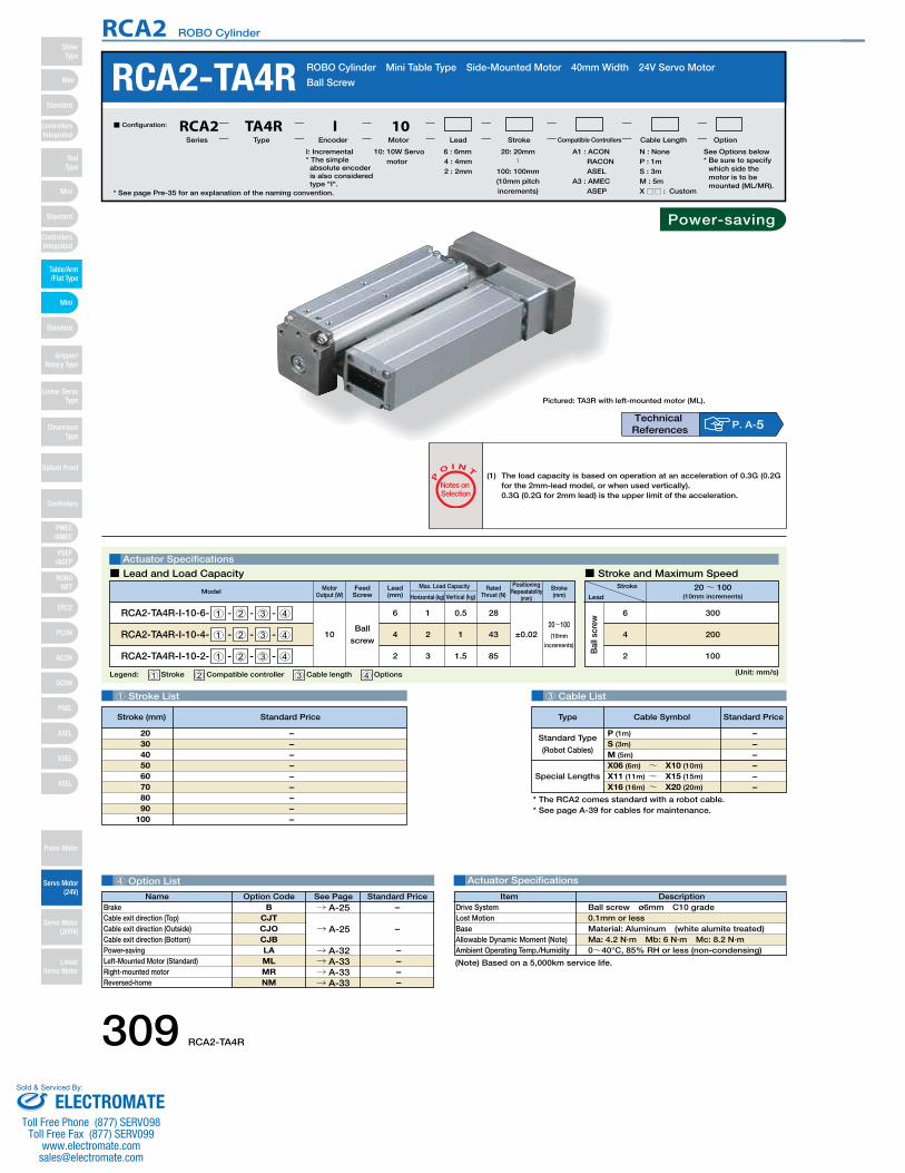
Legend: 1 Stroke 2 Compatible controller 3 Cable length 4 Options
Motor Output (W)
Positioning Repeatability
(mm)
Rated Thrust (N)Model Stroke
(mm)
RCA2-TA4R-I-10-6- 1 - 2 - 3 - 4
RCA2-TA4R-I-10-4- 1 - 2 - 3 - 4
RCA2-TA4R-I-10-2- 1 - 2 - 3 - 4
10Ball
screw
16
24
32
0.5
1
1.5
28
43
85
20~100(1 0mm
increments)
±0.02
Horizontal (kg) Vertical (kg)
Max. Load CapacityLead(mm)
Feed Screw
Bal
l scr
ew
1 Stroke List 3 Cable List
Actuator Specifications
RCA2-TA4R ROBO Cylinder Mini Table Type Side-Mounted Motor 40mm Width 24V Servo Motor
Ball Screw
Actuator Specifications
Stroke
Lead20~ 100
(10mm increments)
300
200
100
6
4
2
■ Lead and Load Capacity ■ Stroke and Maximum Speed
P
O I N T
Notes on Selection
(Unit: mm/s)
* See page Pre-35 for an explanation of the naming convention.
10: 10W Servo motor
I: Incremental* The simple absolute encoder is also considered type "I".
A1 : ACON RACON ASEL
A3 : AMEC ASEP
N : NoneP : 1mS : 3mM : 5mX □□ : Custom
6 : 6mm4 : 4mm2 : 2mm
■ Configuration: RCA2 TA4R I 10Series Type Encoder Motor Lead Stroke Compatible Controllers Cable Length Option
* The RCA2 comes standard with a robot cable.* See page A-39 for cables for maintenance.
Special Lengths
Type Standard PriceCable Symbol
Standard Type
(Robot Cables)
P (1m)
S (3m)
M (5m)
X06 (6m) ~ X10 (10m)
X11 (11m) ~ X15 (15m)
X16 (16m) ~ X20 (20m)
– – – – – –
4 Option List
DescriptionItemBall screw ø6mm C10 grade 0.1mm or lessMaterial: Aluminum (white alumite treated)Ma: 4.2 N∙m Mb: 6 N∙m Mc: 8.2 N∙m 0~40°C, 85% RH or less (non-condensing)
Drive SystemLost MotionBaseAllowable Dynamic Moment (Note)Ambient Operating Temp./Humidity
(1) The load capacity is based on operation at an acceleration of 0.3G (0.2G for the 2mm-lead model, or when used vertically).0.3G (0.2G for 2mm lead) is the upper limit of the acceleration.
– – – – – – – – –
2030405060708090
100
(Note) Based on a 5,000km service life.
Pictured: TA3R with left-mounted motor (ML).
20: 20mm〜
100: 100mm(10mm pitch increments)
Technical References P. A-5
See Options below* Be sure to specify
which side the motor is to be mounted (ML/MR).
Stroke (mm) Standard Price
Name Standard PriceOption Code See PageB
CJTCJOCJBLAMLMRNM
→ A-25
BrakeCable exit direction (Top)Cable exit direction (Outside)Cable exit direction (Bottom)Power-savingLeft-Mounted Motor (Standard)Right-mounted motorReversed-home
–
–
– – – –
→ A-25
→ A-32→ A-33→ A-33→ A-33
Power-saving
309 RCA2-TA4R
RCA2 ROBO Cylinder
Mini
Mini
PSEP/ASEP
PMEC/AMEC
ROBONET
ERC2
PCON
ACON
SCON
PSEL
ASEL
SSEL
XSEL
Standard
Mini
Standard
Standard
ControllersIntegrated
ControllersIntegrated
RodType
Table/Arm/Flat Type
Gripper/Rotary Type
Linear ServoType
Cleanroom Type
Splash Proof
Controllers
Pulse Motor
Servo Motor (24V)
Servo Motor (200V)
LinearServo Motor
SliderType
ELECTROMATEToll Free Phone (877) SERVO98
Toll Free Fax (877) SERV099www.electromate.com
Sold & Serviced By:
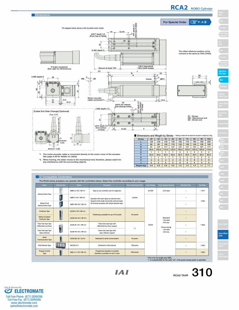
CAD drawings can bedownloaded from IAI website. www.intelligentactuator.com
3-M5 depth 6 29
37
8137.9
3711
3.140
4829
135
5
ME3
SE
ST
8 A 23
B 32L
ME*2Home
19.57D12
J-M4 depth 7.5
31
ø4H7 depth 4.5(from bottom
of base) 5 E×50 F 5
4H7
dept
h 4.
5(fr
om b
otto
m
of b
ase)
5
50(pitch for reamer and oblong holes)
126.2 (standard)158.2 (with brake)
H-M4 depth 6
20
ø4H7 depth 4.5(from top of table)
165
G×40
40
4H7
dept
h 4.
5(fr
om to
p of
tabl
e)
4037
5
If brake-equipped:(See right for dimensions) Secure at least 100
Motor-encodercable connector*1
ST : StrokeME : Mechanical endSE : Stroke end
[Cable Exit Side Change] (Optional)
25
32
(Top: CJT)
Sec
ure
at le
ast 1
00
32
(Outside: CJO)
(Bottom: CJB)
*1 The motor-encoder cable is connected directly to the motor cover of the actuator.See page A-39 for details on cables.
*2 When homing, the slider moves to the mechanical end; therefore, please watch for any interference with the surrounding objects.
Dimensions
■ Dimensions and Weight by StrokeStroke
LABDEFGHJ
Weight (kg)
1298997
90.51
30.5146
0.8
13999107
100.51
40.5146
0.9
149109117
110.51
50.5146
0.9
159119127
120.51
60.5146
0.9
169129137
130.52
20.5268
1.0
179139147
140.52
30.5268
1.0
189149157
150.52
40.5268
1.0
199159167
160.52
50.5268
1.1
209169177
170.52
60.5268
1.1
20 30 40 50 60 70 80 90 100
* Adding a brake will increase the actuator's weight by 0.2kg.
The diagram below shows a left-mounted motor model.
The offset reference position of the moment is the same as TA4C (P302).
For Special Order P. A-9
2 Compatible Controllers
The RCA2 series actuators can operate with the controllers below. Select the controller according to your usage.
* This is for the single-axis ASEL.* 1 is a placeholder for the code "LA", if the power-saving option is specified.
Name External View Model Description Max. Positioning Points Input Voltage Power Supply Capacity Standard Price See Page
Solenoid Valve Type
AMEC-C-10I1-NP-2-1 Easy-to-use controller, even for beginners
3 points
AC100V 2.4A rated – → P477
ASEP-C-10I1-NP-2-0Operable with same signal as solenoid valve.Supports both single and double solenoid types.No homing necessary with simple absolute type.
DC24V
(Standard)1.3A rated4.4A max.
(Power-saving)1.3A rated2.5A max.
–
→ P487Splash-Proof
Solenoid Valve TypeASEP-CW-10I1-NP-2-0 –
Positioner Type ACON-C-10I1-NP-2-0
Positioning is possible for up to 512 points 512 points
–
→ P535
Safety-Compliant Positioner Type
ACON-CG-10I1-NP-2-0 –
Pulse Train Input Type(Differential Line Driver)
ACON-PL-10I1-NP-2-0Pulse train input type with
differential line driver support(−)
–
Pulse Train Input Type(Open Collector)
ACON-PO-10I1-NP-2-0Pulse train input type with
open collector support–
Serial Communication Type
ACON-SE-10I1-N-0-0 Dedicated to serial communication 64 points –
Field Network Type RACON-101 Dedicated to field network 768 points – → P503
Program Control Type
ASEL-C-1-10I1-NP-2-0Programmed operation is possible
Operation is possible on up to 2 axes1500 points – → P567
RCA2-TA4R 310
RCA2 ROBO Cylinder
Mini
Mini
PSEP/ASEP
PMEC/AMEC
ROBONET
ERC2
PCON
ACON
SCON
PSEL
ASEL
SSEL
XSEL
Standard
Mini
Standard
Standard
ControllersIntegrated
ControllersIntegrated
SliderType
RodType
Table/Arm/Flat Type
Gripper/Rotary Type
Linear ServoType
Cleanroom Type
Splash Proof
Controllers
Pulse Motor
Servo Motor (24V)
Servo Motor (200V)
LinearServo Motor
ELECTROMATEToll Free Phone (877) SERVO98
Toll Free Fax (877) SERV099www.electromate.com
Sold & Serviced By:
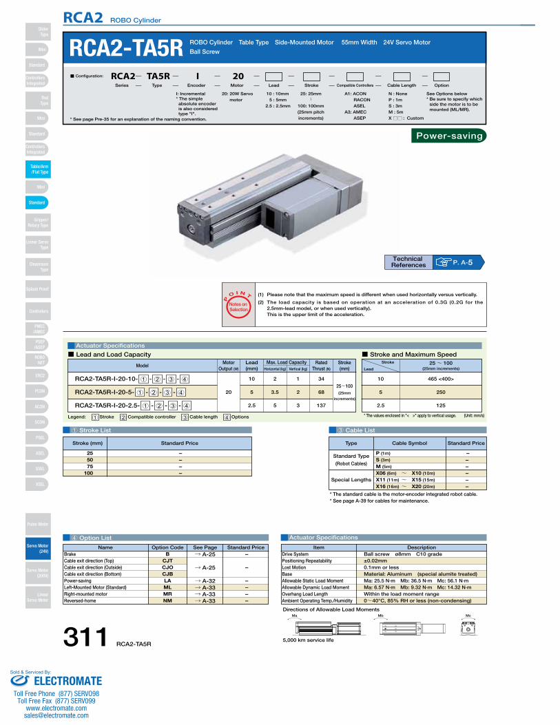
RCA2-TA5R ROBO Cylinder Table Type Side-Mounted Motor 55mm Width 24V Servo Motor
Ball Screw
Ma Mb Mc
Directions of Allowable Load Moments
1 Stroke List 3 Cable List
4 Option List Actuator Specifications
Special Lengths
Type Standard PriceCable Symbol
Standard Type
(Robot Cables)
P (1m)
S (3m)
M (5m)
X06 (6m) ~ X10 (10m)
X11 (11m) ~ X15 (15m)
X16 (16m) ~ X20 (20m)
– – – – – –
* See page Pre-35 for an explanation of the naming convention.
20: 20W Servo motor
A1: ACON RACON ASEL
A3: AMEC ASEP
N : NoneP : 1mS : 3mM : 5mX □□ : Custom
See Options below* Be sure to specify which
side the motor is to be mounted (ML/MR).
25: 25mm〜
100: 100mm(25mm pitch increments)
10 : 10mm5 : 5mm
2.5 : 2.5mm
■ Configuration: RCA2 TA5R I 20Series Type Encoder Motor Lead Stroke Compatible Controllers Cable Length Option
Legend: 1 Stroke 2 Compatible controller 3 Cable length 4 Options (Unit: mm/s)* The values enclosed in "< >" apply to vertical usage.
Actuator Specifications
■ Lead and Load Capacity ■ Stroke and Maximum Speed
(1) Please note that the maximum speed is different when used horizontally versus vertically.
(2) The load capacity is based on operation at an acceleration of 0.3G (0.2G for the 2.5mm-lead model, or when used vertically).This is the upper limit of the acceleration.
P
O I N T
Notes on Selection
Stroke
Lead25~ 100
(25mm increments)
465 <400>
250
125
10
5
2.5
– – – –
255075
100
Motor Output (W)
Lead(mm) Horizontal (kg) Vertical (kg)
Max. Load Capacity Rated Thrust (N)
ModelStroke(mm)
RCA2-TA5R-I-20-10- 1 - 2 - 3 - 4
RCA2-TA5R-I-20-5- 1 - 2 - 3 - 4
RCA2-TA5R-I-20-2.5- 1 - 2 - 3 - 4
20
10
5
2.5
2
3.5
5
1
2
3
34
68
137
25~100(25mm
increments)
Power-saving
P. A-5Technical References
I: Incremental* The simple absolute encoder is also considered type "I".
* The standard cable is the motor-encoder integrated robot cable.* See page A-39 for cables for maintenance.
DescriptionItemBall screw ø8mm C10 grade±0.02mm0.1mm or lessMaterial: Aluminum (special alumite treated)Ma: 25.5 N∙m Mb: 36.5 N∙m Mc: 56.1 N∙mMa: 6.57 N∙m Mb: 9.32 N∙m Mc: 14.32 N∙mWithin the load moment range0~40°C, 85% RH or less (non-condensing)
Drive SystemPositioning RepeatabilityLost MotionBaseAllowable Static Load MomentAllowable Dynamic Load MomentOverhang Load LengthAmbient Operating Temp./Humidity
Stroke (mm) Standard Price
Name Standard PriceOption Code See PageB
CJTCJOCJBLAMLMRNM
→ A-25
BrakeCable exit direction (Top)Cable exit direction (Outside)Cable exit direction (Bottom)Power-savingLeft-Mounted Motor (Standard)Right-mounted motorReversed-home
–
–
– – – –
→ A-25
→ A-32→ A-33→ A-33→ A-33
5,000 km service life311 RCA2-TA5R
RCA2 ROBO Cylinder
Mini
Mini
PSEP/ASEP
PMEC/AMEC
ROBONET
ERC2
PCON
ACON
SCON
PSEL
ASEL
SSEL
XSEL
Standard
Mini
Standard
Standard
ControllersIntegrated
ControllersIntegrated
RodType
Table/Arm/Flat Type
Gripper/Rotary Type
Linear ServoType
Cleanroom Type
Splash Proof
Controllers
Pulse Motor
Servo Motor (24V)
Servo Motor (200V)
LinearServo Motor
SliderType
ELECTROMATEToll Free Phone (877) SERVO98
Toll Free Fax (877) SERV099www.electromate.com
Sold & Serviced By:
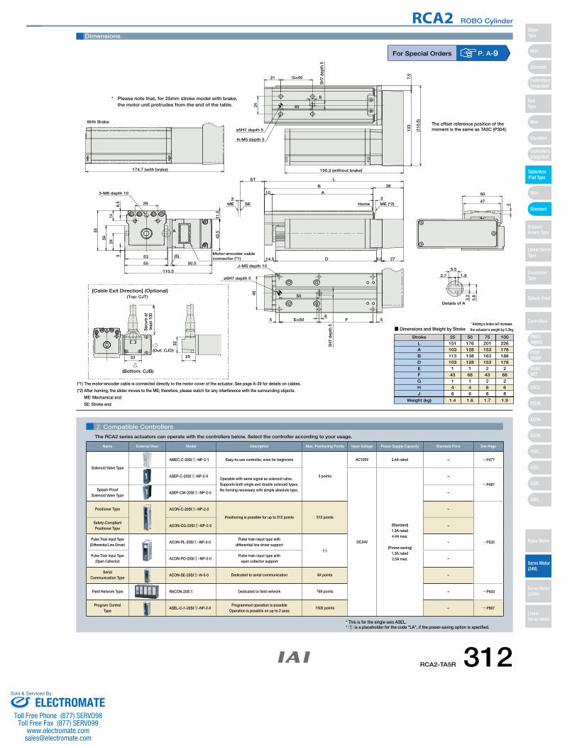
CAD drawings can bedownloaded from IAI website. www.intelligentactuator.com
53
55
(5)
50.5
110.5
5
24
34
6.5
14
55
29
43.5
3-M6 depth 10
11.5
50
5 E×50 F 5
45
5H7
dept
h 5
6
J-M5 depth 10
3.3
5.8
1.82.7
5.5
174.7 (with brake)
With Brake
ø5H7 depth 5
Details of A
Motor-encoder cableconnector (*1)
A
G×40
5H7
dept
h 5
ø5H7 depth 5
H-M5 depth 5
150.2 (without brake)
(110
.5)
ME (*2)HomeSEME 5
50
47
103
7.5
6
24
21
40
38
L
B
A10
276.5D14.5
3
ST
3
[Cable Exit Direction] (Optional)
Sec
ure
at
leas
t 100
32 25
32
(Top: CJT)
(Out: CJO)
(Bottom: CJB)
(*1) The motor-encoder cable is connected directly to the motor cover of the actuator. See page A-39 for details on cables.
(*2) After homing, the slider moves to the ME; therefore, please watch for any interference with the surrounding objects.
ME: Mechanical end
SE: Stroke end
* Adding a brake will increase the actuator's weight by 0.3kg.
Stroke 25 50 75 100
■ Dimensions and Weight by Stroke
151 176 201 226 103 128 153 178 113 138 163 188 103 128 153 178
1 1 2 2 43 68 43 68 1 1 2 2 4 4 6 6 6 6 8 8
1.4 1.6 1.7 1.9
LABDEFGHJ
Weight (kg)
* Please note that, for 25mm stroke model with brake, the motor unit protrudes from the end of the table.
Dimensions
For Special Orders P. A-9
2 Compatible Controllers
The RCA2 series actuators can operate with the controllers below. Select the controller according to your usage.
* This is for the single-axis ASEL.* 1 is a placeholder for the code "LA", if the power-saving option is specified.
Name External View Model Description Max. Positioning Points Input Voltage Power Supply Capacity Standard Price See Page
Solenoid Valve Type
AMEC-C-20SI1-NP-2-1 Easy-to-use controller, even for beginners
3 points
AC100V 2.4A rated – → P477
ASEP-C-20SI1-NP-2-0Operable with same signal as solenoid valve.Supports both single and double solenoid types.No homing necessary with simple absolute type.
DC24V
(Standard)1.3A rated4.4A max.
(Power-saving)1.3A rated2.5A max.
–
→ P487Splash-Proof
Solenoid Valve TypeASEP-CW-20SI1-NP-2-0 –
Positioner Type ACON-C-20SI1-NP-2-0
Positioning is possible for up to 512 points 512 points
–
→ P535
Safety-Compliant Positioner Type
ACON-CG-20SI1-NP-2-0 –
Pulse Train Input Type(Differential Line Driver)
ACON-PL-20SI1-NP-2-0Pulse train input type with
differential line driver support(−)
–
Pulse Train Input Type(Open Collector)
ACON-PO-20SI1-NP-2-0Pulse train input type with
open collector support–
Serial Communication Type
ACON-SE-20SI1-N-0-0 Dedicated to serial communication 64 points –
Field Network Type RACON-20S1 Dedicated to field network 768 points – → P503
Program Control Type
ASEL-C-1-20SI1-NP-2-0Programmed operation is possible
Operation is possible on up to 2 axes1500 points – → P567
The offset reference position of the moment is the same as TA5C (P304).
RCA2-TA5R 312
RCA2 ROBO Cylinder
Mini
Mini
PSEP/ASEP
PMEC/AMEC
ROBONET
ERC2
PCON
ACON
SCON
PSEL
ASEL
SSEL
XSEL
Standard
Mini
Standard
Standard
ControllersIntegrated
ControllersIntegrated
SliderType
RodType
Table/Arm/Flat Type
Gripper/Rotary Type
Linear ServoType
Cleanroom Type
Splash Proof
Controllers
Pulse Motor
Servo Motor (24V)
Servo Motor (200V)
LinearServo Motor
ELECTROMATEToll Free Phone (877) SERVO98
Toll Free Fax (877) SERV099www.electromate.com
Sold & Serviced By:

RCA2-TA6R ROBO Cylinder Table Type Side-Mounted Motor 65mm Width 24V Servo Motor
Ball Screw
Motor Output (W)
Lead(mm) Horizontal (kg) Vertical (kg)
Max. Load Capacity Rated Thrust (N)
ModelStroke(mm)
RCA2-TA6R-I-20-12- 1 - 2 - 3 - 4
RCA2-TA6R-I-20-6- 1 - 2 - 3 - 4
RCA2-TA6R-I-20-3- 1 - 2 - 3 - 4
20
12
6
3
2
4
6
0.5
1.5
3
17
34
68
25~150(25mm
increments)
Ma Mb McDirections of Allowable Load Moments
1 Stroke List 3 Cable List
4 Option List Actuator Specifications
* See page Pre-35 for an explanation of the naming convention.
20: 20W Servo motor
A1: ACON RACON ASEL
A3: AMEC ASEP
N : NoneP : 1mS : 3mM : 5mX □□ : Custom
25: 25mm〜
150: 150mm(25mm pitch increments)
12 : 12mm6 : 6mm3 : 3mm
■ Configuration: RCA2 TA6R I 20Series Type Encoder Motor Lead Stroke Compatible Controllers Cable Length Option
Legend: 1 Stroke 2 Compatible controller 3 Cable length 4 Options (Unit: mm/s)* The values enclosed in "< >" apply to vertical usage.
Actuator Specifications
■ Lead and Load Capacity ■ Stroke and Maximum Speed
(1) Please note that the maximum speed is different when used horizontally versus vertically.
(2) The load capacity is based on operation at an acceleration of 0.3G (0.2G for the 3mm-lead model, or when used vertically).This is the upper limit of the acceleration.
P
O I N T
Notes on Selection
Stroke
Lead25~ 150
(25mm increments)
560 <500>
300
150
12
6
3
– – – – – –
255075
100125150
Special Lengths
Type Standard PriceCable Symbol
Standard Type
(Robot Cables)
P (1m)
S (3m)
M (5m)
X06 (6m) ~ X10 (10m)
X11 (11m) ~ X15 (15m)
X16 (16m) ~ X20 (20m)
– – – – – –
P. A-5Technical References
I: Incremental* The simple absolute encoder is also considered type "I".
* The standard cable is the motor-encoder integrated robot cable.* See page A-39 for cables for maintenance.
DescriptionItemBall screw ø10mm C10 grade±0.02mm0.1mm or lessMaterial: Aluminum (special alumite treated)Ma: 29.4 N∙m Mb: 42.0 N∙m Mc: 74.1 N∙mMa: 7.26 N∙m Mb: 10.3 N∙m Mc: 18.25 N∙mWithin the load moment range0~40°C, 85% RH or less (non-condensing)
Drive SystemPositioning RepeatabilityLost MotionBaseAllowable Static Load MomentAllowable Dynamic Load MomentOverhang Load LengthAmbient Operating Temp./Humidity
Stroke (mm) Standard Price
See Options below* Be sure to specify which
side the motor is to be mounted (ML/MR).
Name Standard PriceOption Code See PageB
CJTCJOCJBLAMLMRNM
→ A-25
BrakeCable exit direction (Top)Cable exit direction (Outside)Cable exit direction (Bottom)Power-savingLeft-Mounted Motor (Standard)Right-mounted motorReversed-home
–
–
– – – –
→ A-25
→ A-32→ A-33→ A-33→ A-33
Power-saving
5,000 km service life313 RCA2-TA6R
RCA2 ROBO Cylinder
Mini
Mini
PSEP/ASEP
PMEC/AMEC
ROBONET
ERC2
PCON
ACON
SCON
PSEL
ASEL
SSEL
XSEL
Standard
Mini
Standard
Standard
ControllersIntegrated
ControllersIntegrated
RodType
Table/Arm/Flat Type
Gripper/Rotary Type
Linear ServoType
Cleanroom Type
Splash Proof
Controllers
Pulse Motor
Servo Motor (24V)
Servo Motor (200V)
LinearServo Motor
SliderType
ELECTROMATEToll Free Phone (877) SERVO98
Toll Free Fax (877) SERV099www.electromate.com
Sold & Serviced By:
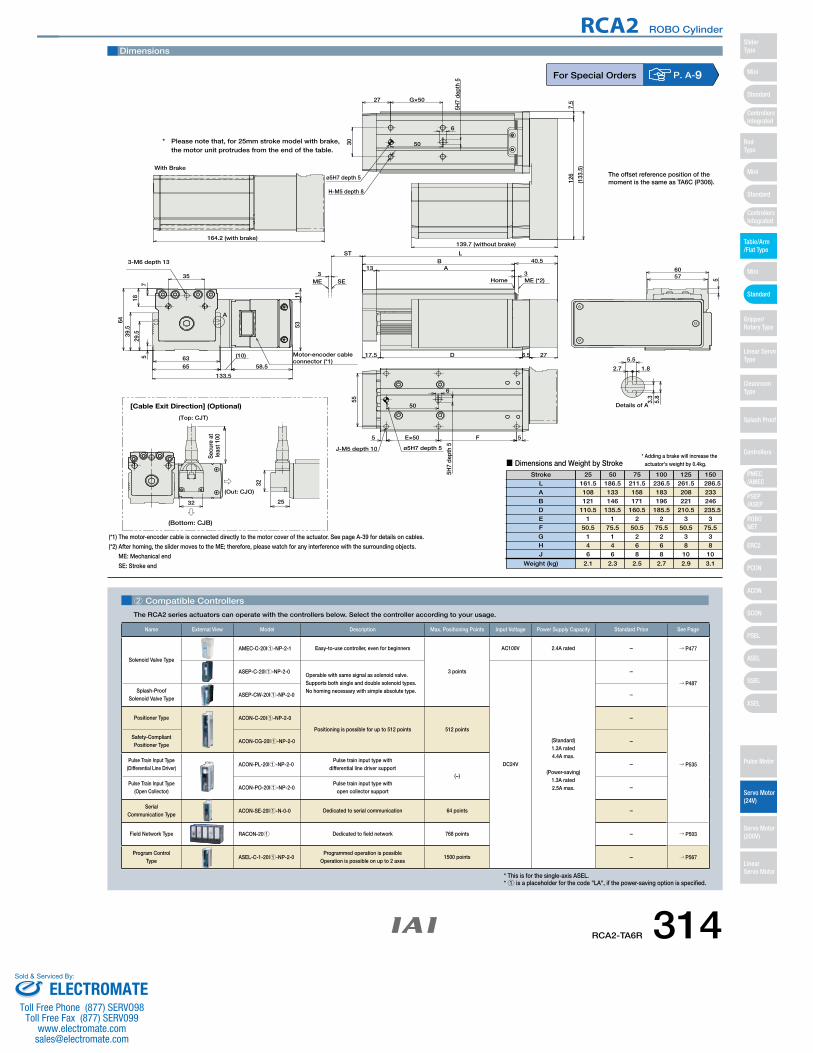
CAD drawings can bedownloaded from IAI website. www.intelligentactuator.com
35
57
1829
.539.5
64
6365
(10)
58.5
133.5
53
3-M6 depth 13
11
50
55
E×505 F 5
6
5H7
dept
h 5
J-M5 depth 10
3.3
5.8
1.82.7
5.5
164.2 (with brake)
With Brake
Motor-encoder cableconnector (*1)
Details of A
ø5H7 depth 5
A
G×50
5H7
dept
h 5
(133
.5)
139.7 (without brake)
ø5H7 depth 5
H-M5 depth 8
ME (*2)HomeSEME 5
6057
30
6
27
126
7.5
50
L40.5B
A13
276.5D17.5
3
ST
3
[Cable Exit Direction] (Optional)
(Top: CJT)
32 25
32
(Out: CJO)
(Bottom: CJB)
Sec
ure
at
leas
t 100
(*1) The motor-encoder cable is connected directly to the motor cover of the actuator. See page A-39 for details on cables.
(*2) After homing, the slider moves to the ME; therefore, please watch for any interference with the surrounding objects.
ME: Mechanical end
SE: Stroke end
* Adding a brake will increase the actuator's weight by 0.4kg.
Stroke 25 50 75 100 125 150
■ Dimensions and Weight by Stroke
161.5 186.5 211.5 236.5 261.5 286.5108 133 158 183 208 233 121 146 171 196 221 246
110.5 135.5 160.5 185.5 210.5 235.51 1 2 2 3 3
50.5 75.5 50.5 75.5 50.5 75.5 1 1 2 2 3 3 4 4 6 6 8 8 6 6 8 8 10 10
2.1 2.3 2.5 2.7 2.9 3.1
LABDEFGHJ
Weight (kg)
* Please note that, for 25mm stroke model with brake, the motor unit protrudes from the end of the table.
Dimensions
For Special Orders P. A-9
2 Compatible Controllers
The RCA2 series actuators can operate with the controllers below. Select the controller according to your usage.
* This is for the single-axis ASEL.* 1 is a placeholder for the code "LA", if the power-saving option is specified.
Name External View Model Description Max. Positioning Points Input Voltage Power Supply Capacity Standard Price See Page
Solenoid Valve Type
AMEC-C-20I1-NP-2-1 Easy-to-use controller, even for beginners
3 points
AC100V 2.4A rated – → P477
ASEP-C-20I1-NP-2-0Operable with same signal as solenoid valve.Supports both single and double solenoid types.No homing necessary with simple absolute type.
DC24V
(Standard)1.3A rated4.4A max.
(Power-saving)1.3A rated2.5A max.
–
→ P487Splash-Proof
Solenoid Valve TypeASEP-CW-20I1-NP-2-0 –
Positioner Type ACON-C-20I1-NP-2-0
Positioning is possible for up to 512 points 512 points
–
→ P535
Safety-Compliant Positioner Type
ACON-CG-20I1-NP-2-0 –
Pulse Train Input Type(Differential Line Driver)
ACON-PL-20I1-NP-2-0Pulse train input type with
differential line driver support(−)
–
Pulse Train Input Type(Open Collector)
ACON-PO-20I1-NP-2-0Pulse train input type with
open collector support–
Serial Communication Type
ACON-SE-20I1-N-0-0 Dedicated to serial communication 64 points –
Field Network Type RACON-201 Dedicated to field network 768 points – → P503
Program Control Type
ASEL-C-1-20I1-NP-2-0Programmed operation is possible
Operation is possible on up to 2 axes1500 points – → P567
The offset reference position of the moment is the same as TA6C (P306).
RCA2-TA6R 314
RCA2 ROBO Cylinder
Mini
Mini
PSEP/ASEP
PMEC/AMEC
ROBONET
ERC2
PCON
ACON
SCON
PSEL
ASEL
SSEL
XSEL
Standard
Mini
Standard
Standard
ControllersIntegrated
ControllersIntegrated
SliderType
RodType
Table/Arm/Flat Type
Gripper/Rotary Type
Linear ServoType
Cleanroom Type
Splash Proof
Controllers
Pulse Motor
Servo Motor (24V)
Servo Motor (200V)
LinearServo Motor
ELECTROMATEToll Free Phone (877) SERVO98
Toll Free Fax (877) SERV099www.electromate.com
Sold & Serviced By:
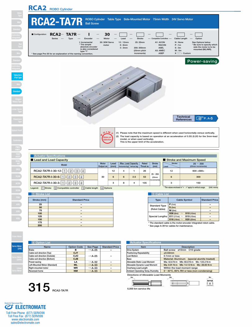
RCA2-TA7R ROBO Cylinder Table Type Side-Mounted Motor 75mm Width 24V Servo Motor
Ball Screw
Motor Output (W)
Lead(mm) Horizontal (kg) Vertical (kg)
Max. Load Capacity Rated Thrust (N)
ModelStroke(mm)
RCA2-TA7R-I-30-12- 1 - 2 - 3 - 4
RCA2-TA7R-I-30-6- 1 - 2 - 3 - 4
RCA2-TA7R-I-30-3- 1 - 2 - 3 - 4
30
12
6
3
4
6
8
1
2.5
4
26
53
105
25~200(25mm
increments)
Ma Mb McDirections of Allowable Load Moments
1 Stroke List 3 Cable List
4 Option List Actuator Specifications
Special Lengths
Type Standard PriceCable Symbol
Standard Type
(Robot Cables)
P (1m)
S (3m)
M (5m)
X06 (6m) ~ X10 (10m)
X11 (11m) ~ X15 (15m)
X16 (16m) ~ X20 (20m)
– – – – – –
* See page Pre-35 for an explanation of the naming convention.
30: 30W Servo motor
A1: ACONRACONASEL
A3: AMECASEP
N : NoneP : 1mS : 3mM : 5mX □□ : Custom
25: 25mm〜
200: 200mm(25mm pitch increments)
12 : 12mm6 : 6mm3 : 3mm
■ Configuration: RCA2 TA7R I 30Series Type Encoder Motor Lead Stroke Compatible Controllers Cable Length Option
Legend: 1 Stroke 2 Compatible controller 3 Cable length 4 Options (Unit: mm/s)* The values enclosed in "< >" apply to vertical usage.
Actuator Specifications
■ Lead and Load Capacity ■ Stroke and Maximum Speed
(1) Please note that the maximum speed is different when used horizontally versus vertically.
(2) The load capacity is based on operation at an acceleration of 0.3G (0.2G for the 3mm-lead model, or when used vertically).This is the upper limit of the acceleration.
P
O I N T
Notes on Selection
Stroke
Lead25~ 200
(25mm increments)
600 <580>
300
150
12
6
3
– – – – – – – –
255075
100125150175200
P. A-5Technical References
I: Incremental* The simple absolute encoder is also considered type "I".
* The standard cable is the motor-encoder integrated robot cable.* See page A-39 for cables for maintenance.
DescriptionItemBall screw ø10mm C10 grade±0.02mm0.1mm or lessMaterial: Aluminum (special alumite treated)Ma: 42.6 N∙m Mb: 60.8 N∙m Mc: 123.2 N∙mMa: 9.91 N∙m Mb: 14.13 N∙m Mc: 28.65 N∙mWithin the load moment range0~40°C, 85% RH or less (non-condensing)
Drive SystemPositioning RepeatabilityLost MotionBaseAllowable Static Load MomentAllowable Dynamic Load MomentOverhang Load LengthAmbient Operating Temp./Humidity
Stroke (mm) Standard Price
See Options below* Be sure to specify which
side the motor is to be mounted (ML/MR).
Name Standard PriceOption Code See PageB
CJTCJOCJBLAMLMRNM
→ A-25
BrakeCable exit direction (Top)Cable exit direction (Outside)Cable exit direction (Bottom)Power-savingLeft-Mounted Motor (Standard)Right-mounted motorReversed-home
–
–
– – – –
→ A-25
→ A-32→ A-33→ A-33→ A-33
Power-saving
5,000 km service life315 RCA2-TA7R
RCA2 ROBO Cylinder
Mini
Mini
PSEP/ASEP
PMEC/AMEC
ROBONET
ERC2
PCON
ACON
SCON
PSEL
ASEL
SSEL
XSEL
Standard
Mini
Standard
Standard
ControllersIntegrated
ControllersIntegrated
RodType
Table/Arm/Flat Type
Gripper/Rotary Type
Linear ServoType
Cleanroom Type
Splash Proof
Controllers
Pulse Motor
Servo Motor (24V)
Servo Motor (200V)
LinearServo Motor
SliderType
ELECTROMATEToll Free Phone (877) SERVO98
Toll Free Fax (877) SERV099www.electromate.com
Sold & Serviced By:
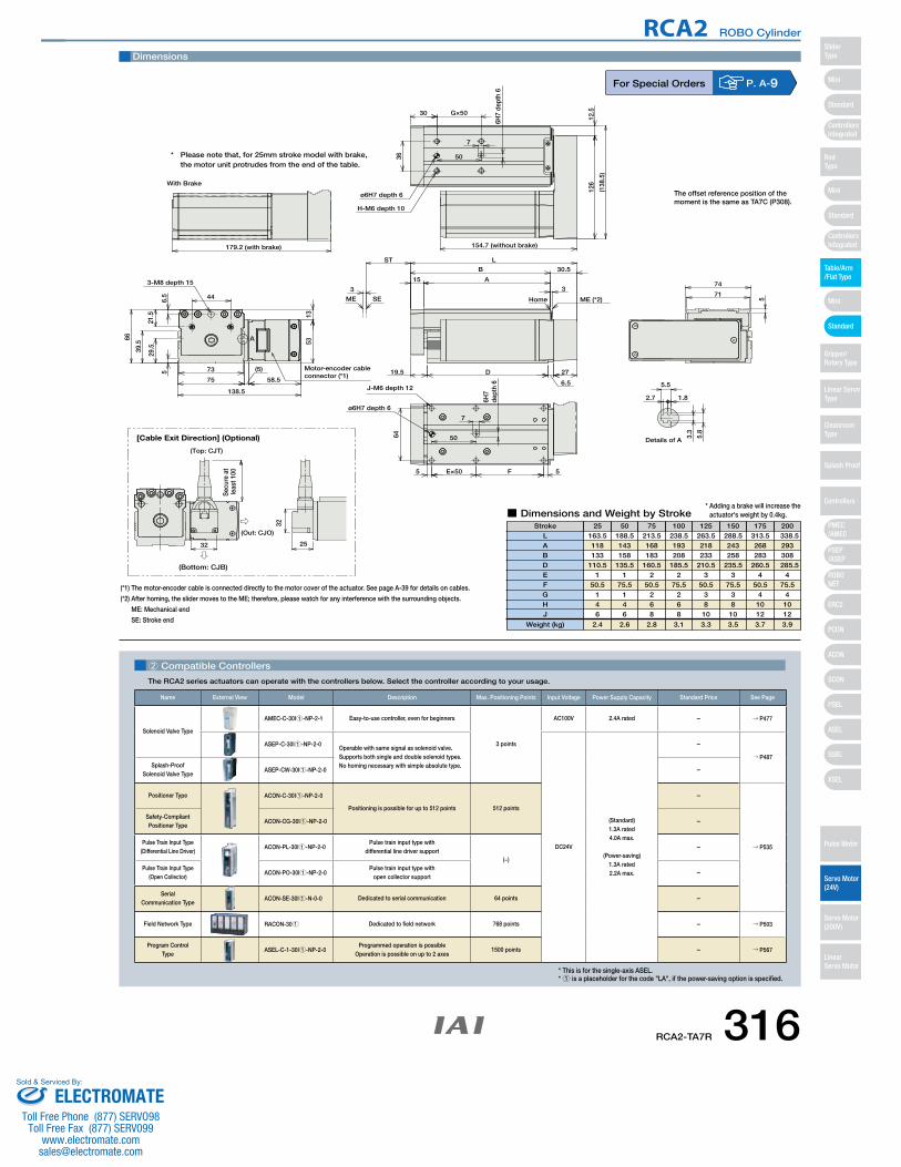
CAD drawings can bedownloaded from IAI website. www.intelligentactuator.com
(*1) The motor-encoder cable is connected directly to the motor cover of the actuator. See page A-39 for details on cables.
(*2) After homing, the slider moves to the ME; therefore, please watch for any interference with the surrounding objects.
ME: Mechanical end
SE: Stroke end
446.5
5
29.5
21.5
66
39.5
73
75
(5)
58.5
138.5
3-M8 depth 15
5313
50
5 E×50 F 5
64
7
6H7
dept
h 6
3.3
5.8
1.82.7
5.5
Details of A
179.2 (with brake)
With Brake
J-M6 depth 12
ø6H7 depth 6
A
Motor-encoder cableconnector (*1)
126
12.5
7
36
30
50
G×50
6H7
dept
h 6
ø6H7 depth 6
H-M6 depth 10
154.7 (without brake)
(138
.5)
27
6.5
D19.5
30.5
L
B
A15
3
ST
3
ME (*2)HomeSEME 5
74
71
[Cable Exit Direction] (Optional)
(Top: CJT)
32 25
32
(Out: CJO)
(Bottom: CJB)
Sec
ure
at
leas
t 100
* Adding a brake will increase the actuator's weight by 0.4kg.
Stroke 25 50 75 100 125 150 175 200
■ Dimensions and Weight by Stroke
163.5 188.5 213.5 238.5 263.5 288.5 313.5 338.5118 143 168 193 218 243 268 293 133 158 183 208 233 258 283 308
110.5 135.5 160.5 185.5 210.5 235.5 260.5 285.51 1 2 2 3 3 4 4
50.5 75.5 50.5 75.5 50.5 75.5 50.5 75.5 1 1 2 2 3 3 4 4 4 4 6 6 8 8 10 10 6 6 8 8 10 10 12 12
2.4 2.6 2.8 3.1 3.3 3.5 3.7 3.9
LABDEFGHJ
Weight (kg)
* Please note that, for 25mm stroke model with brake, the motor unit protrudes from the end of the table.
Dimensions
For Special Orders P. A-9
2 Compatible Controllers
The RCA2 series actuators can operate with the controllers below. Select the controller according to your usage.
* This is for the single-axis ASEL.* 1 is a placeholder for the code "LA", if the power-saving option is specified.
Name External View Model Description Max. Positioning Points Input Voltage Power Supply Capacity Standard Price See Page
Solenoid Valve Type
AMEC-C-30I1-NP-2-1 Easy-to-use controller, even for beginners
3 points
AC100V 2.4A rated – → P477
ASEP-C-30I1-NP-2-0Operable with same signal as solenoid valve.Supports both single and double solenoid types.No homing necessary with simple absolute type.
DC24V
(Standard)1.3A rated4.0A max.
(Power-saving)1.3A rated2.2A max.
–
→ P487Splash-Proof
Solenoid Valve TypeASEP-CW-30I1-NP-2-0 –
Positioner Type ACON-C-30I1-NP-2-0
Positioning is possible for up to 512 points 512 points
–
→ P535
Safety-Compliant Positioner Type
ACON-CG-30I1-NP-2-0 –
Pulse Train Input Type(Differential Line Driver)
ACON-PL-30I1-NP-2-0Pulse train input type with
differential line driver support(−)
–
Pulse Train Input Type(Open Collector)
ACON-PO-30I1-NP-2-0Pulse train input type with
open collector support–
Serial Communication Type
ACON-SE-30I1-N-0-0 Dedicated to serial communication 64 points –
Field Network Type RACON-301 Dedicated to field network 768 points – → P503
Program Control Type
ASEL-C-1-30I1-NP-2-0Programmed operation is possible
Operation is possible on up to 2 axes1500 points – → P567
The offset reference position of the moment is the same as TA7C (P308).
RCA2-TA7R 316
RCA2 ROBO Cylinder
Mini
Mini
PSEP/ASEP
PMEC/AMEC
ROBONET
ERC2
PCON
ACON
SCON
PSEL
ASEL
SSEL
XSEL
Standard
Mini
Standard
Standard
ControllersIntegrated
ControllersIntegrated
SliderType
RodType
Table/Arm/Flat Type
Gripper/Rotary Type
Linear ServoType
Cleanroom Type
Splash Proof
Controllers
Pulse Motor
Servo Motor (24V)
Servo Motor (200V)
LinearServo Motor
ELECTROMATEToll Free Phone (877) SERVO98
Toll Free Fax (877) SERV099www.electromate.com
Sold & Serviced By:
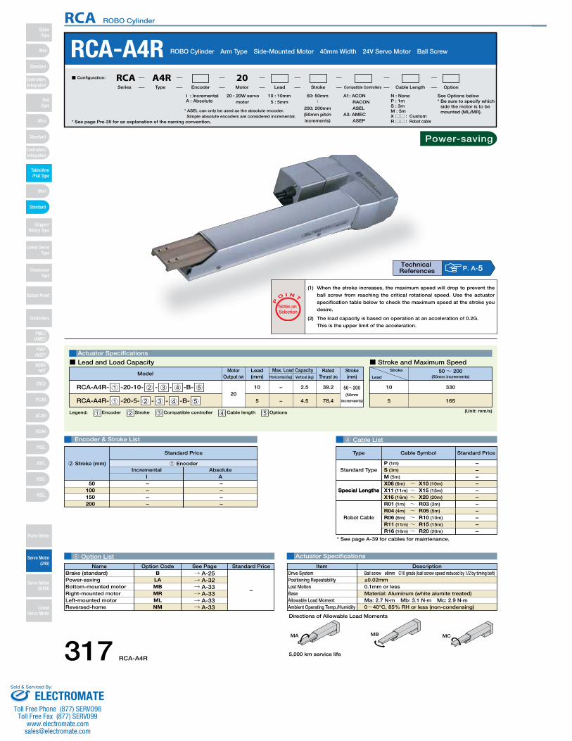
DescriptionItemBall screw ø8mm C10 grade (ball screw speed reduced by 1/2 by timing belt)±0.02mm0.1mm or lessMaterial: Aluminum (white alumite treated)Ma: 2.7 N∙m Mb: 3.1 N∙m Mc: 2.9 N∙m0~40°C, 85% RH or less (non-condensing)
Drive SystemPositioning RepeatabilityLost MotionBaseAllowable Load MomentAmbient Operating Temp./Humidity
MA MB MC
Special Lengths
Type Standard PriceCable Symbol
SA4D : Aluminum
base
SS4D : Steel base
Name Standard PriceOption Code See PageB
LAMBMRMLNM
→ A-25→ A-32→ A-33→ A-33→ A-33→ A-33
Brake (standard)Power-savingBottom-mounted motorRight-mounted motorLeft-mounted motorReversed-home
–
4 Cable List
5 Option List Actuator Specifications
RCA-A4R ROBO Cylinder Arm Type Side-Mounted Motor 40mm Width 24V Servo Motor Ball Screw
Actuator Specifications
■ Lead and Load Capacity ■ Stroke and Maximum Speed
P
O I N T
Notes on Selection
(1) When the stroke increases, the maximum speed will drop to prevent the
ball screw from reaching the critical rotational speed. Use the actuator
specification table below to check the maximum speed at the stroke you
desire.
(2) The load capacity is based on operation at an acceleration of 0.2G.
This is the upper limit of the acceleration.
20 : 20W servo motor
I : IncrementalA : Absolute
A1: ACON RACON ASEL
A3: AMEC ASEP
N : NoneP : 1mS : 3mM : 5mX □□ : CustomR□□ : Robot cable
50: 50mm〜
200: 200mm(50mm pitch increments)
10 : 10mm5 : 5mm
■ Configuration: RCA A4R 20Series Type Encoder Motor Lead Stroke Compatible Controllers Cable Length Option
Legend: 1 Encoder 2 Stroke 3 Compatible controller 4 Cable length 5 Options
Motor Output (W)
Lead(mm) Horizontal (kg) Vertical (kg)
Max. Load Capacity Rated Thrust (N)
ModelStroke(mm)
RCA-A4R- 1 -20-10- 2 - 3 - 4 -B- 5
RCA-A4R- 1 -20-5- 2 - 3 - 4 -B- 520
10
5
−
−
2.5
4.5
39.2
78.4
50~200(50mm
increments)
(Unit: mm/s)
Stroke
Lead50~ 200
(50mm increments)
330
165
10
5
Encoder & Stroke List
– – – –
– – – –
Incremental AbsoluteI
50100150200
A
Standard Price
1 Encoder2 Stroke (mm)
Special Lengths
Type Standard PriceCable Symbol
Standard Type
Robot Cable
P (1m)
S (3m)
M (5m)
X06 (6m) ~ X10 (10m)
X11 (11m) ~ X15 (15m)
X16 (16m) ~ X20 (20m)
R01 (1m) ~ R03 (3m)
R04 (4m) ~ R05 (5m)
R06 (6m) ~ R10 (10m)
R11 (11m) ~ R15 (15m)
R16 (16m) ~ R20 (20m)
– – – – – – – – – – –
* See page A-39 for cables for maintenance.
* See page Pre-35 for an explanation of the naming convention.
P. A-5Technical References
Power-saving
Directions of Allowable Load Moments
See Options below* Be sure to specify which
side the motor is to be mounted (ML/MR).
5,000 km service life
* ASEL can only be used as the absolute encoder.Simple absolute encoders are considered incremental.
317 RCA-A4R
RCA ROBO Cylinder
Mini
Mini
PSEP/ASEP
PMEC/AMEC
ROBONET
ERC2
PCON
ACON
SCON
PSEL
ASEL
SSEL
XSEL
Standard
Mini
Standard
Standard
ControllersIntegrated
ControllersIntegrated
RodType
Table/Arm/Flat Type
Gripper/Rotary Type
Linear ServoType
Cleanroom Type
Splash Proof
Controllers
Pulse Motor
Servo Motor (24V)
Servo Motor (200V)
LinearServo Motor
SliderType
ELECTROMATEToll Free Phone (877) SERVO98
Toll Free Fax (877) SERV099www.electromate.com
Sold & Serviced By:
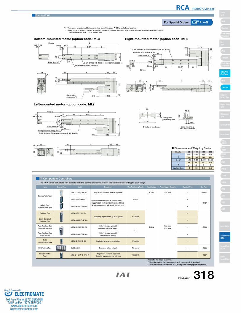
For Special Orders P. A-9
3 Compatible Controllers
The RCA series actuators can operate with the controllers below. Select the controller according to your usage.
* This is for the single-axis ASEL.* 1 is a placeholder for the encoder type (I: incremental, A: absolute). * 2 is a placeholder for the code "LA", if the power-saving option is specified.
(2)
4-M4 depth 5
ME SE ME*2Home
E-3.6 drilled 6.5 deep counterbore 3.3 (back)
Moment reference position
3 3 D90
2040 52
B×CP
5 10
16
3035
LStroke
4652
105
337
101.
5
A
122.5(13)
Workpiece mounting area
ø3.6
ø6.5
2.25
33
(33.4)
Base mounting hole cross section
Details of section A
Workpiece mounting area53
52
(2)
4-M4 depth 5
40
33
Stroke L
122.5
Home ME
1.5
10
373
52 4635 30
105
90
105
20
D
E-3.6 drilled 6.5 counterbore depth 3.3 (back)
A
(13)
SEME
Workpiece mounting area53
52
(2)
4-M4 depth 5
40
33Stroke L
122.5
Home ME
1.5
10
373
52 4635 30
105
90
105
20
D
E-3.6 drilled 6.5 counterbore depth 3.3 (back)
A
(13)
SEME
B×CP
B×CP
Bottom-mounted motor (option code: MB)
Left-mounted motor (option code: ML)
Right-mounted motor (option code: MR)
Cable jointconnector*1
ℓ
ℓ
ℓ
Dimensions
*1 The motor-encoder cable is connected here. See page A-39 for details on cables.*2 When homing, the rod moves to the ME; therefore, please watch for any interference with the surrounding objects.
ME: Mechanical end SE: Stroke end
Stroke 50 100 150 200
Lℓ
B×CP
DE
Weight (kg)
255144
1×19354
1.7
305194
1×50544
1.8
355244
2×50546
2.0
405294
2×50104
6
2.1
■ Dimensions and Weight by Stroke
Name External View Model Description Max. Positioning Points Input Voltage Power Supply Capacity Standard Price See Page
Solenoid Valve Type
AMEC–C–20I2–NP–2–1 Easy–to–use controller, even for beginners
3 points
AC100V 2.4A rated – → P477
ASEP-C-20I2-NP-2-0Operable with same signal as solenoid valve.Supports both single and double solenoid types.No homing necessary with simple absolute type.
DC24V1.3A rated4.4A peak
–
→ P487Splash-Proof
Solenoid Valve TypeASEP-CW-20I2-NP-2-0 –
Positioner Type ACON-C-20I2-NP-2-0
Positioning is possible for up to 512 points 512 points
–
→ P535
Safety-Compliant Positioner Type
ACON-CG-20I2-NP-2-0 –
Pulse Train Input Type(Differential Line Driver)
ACON-PL-20I2-NP-2-0Pulse train input type with
differential line driver support(−)
–
Pulse Train Input Type(Open Collector)
ACON-PO-20I2-NP-2-0Pulse train input type with
open collector support–
Serial Communication Type
ACON-SE-20I2-N-0-0 Dedicated to serial communication 64 points –
Field Network Type RACON-202 Dedicated to field network 768 points – → P503
Program Control Type
ASEL-C-1-2012-NP-2-0Programmed operation is possible
Operation is possible on up to 2 axes1500 points – → P567
RCA-A4R 318
RCA ROBO Cylinder
Mini
Mini
PSEP/ASEP
PMEC/AMEC
ROBONET
ERC2
PCON
ACON
SCON
PSEL
ASEL
SSEL
XSEL
Standard
Mini
Standard
Standard
ControllersIntegrated
ControllersIntegrated
SliderType
RodType
Table/Arm/Flat Type
Gripper/Rotary Type
Linear ServoType
Cleanroom Type
Splash Proof
Controllers
Pulse Motor
Servo Motor (24V)
Servo Motor (200V)
LinearServo Motor
ELECTROMATEToll Free Phone (877) SERVO98
Toll Free Fax (877) SERV099www.electromate.com
Sold & Serviced By:
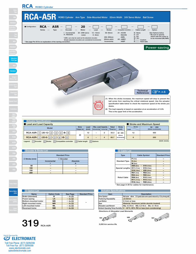
DescriptionItemBall screw ø8mm C10 grade (ball screw speed reduced by 1/2 by timing belt)±0.02mm0.1mm or lessMaterial: Aluminum (white alumite treated)Ma: 4.5 N∙m Mb: 5.4 N∙m Mc: 4.1 N∙m0~40°C, 85% RH or less (non-condensing)
Drive SystemPositioning RepeatabilityLost MotionBaseAllowable Load MomentAmbient Operating Temp./Humidity
Directions of Allowable Load Moments
SA4D : Aluminum
base
SS4D : Steel base
4 Cable List
5 Option List Actuator Specifications
RCA-A5R ROBO Cylinder Arm Type Side-Mounted Motor 52mm Width 24V Servo Motor Ball Screw
Actuator Specifications
■ Lead and Load Capacity ■ Stroke and Maximum Speed
P
O I N T
Notes on Selection
(1) When the stroke increases, the maximum speed will drop to prevent the
ball screw from reaching the critical rotational speed. Use the actuator
specification table below to check the maximum speed at the stroke you
desire.
(2) The load capacity is based on operation at an acceleration of 0.2G.
This is the upper limit of the acceleration.
20 : 20W servo motor
I : IncrementalA : Absolute
A1 : ACON RACON ASEL
A3 : AMEC ASEP
N : NoneP : 1mS : 3mM : 5mX □□ : CustomR□□ : Robot cable
See Options below* Be sure to specify
which side the motor is to be mounted (ML/MR).
50: 50mm〜
200: 200mm(50mm pitch increments)
12 : 12mm6 : 6mm
■ Configuration: RCA A5R 20Series Type Encoder Motor Lead Stroke Compatible Controllers Cable Length Option
Legend: 1 Encoder 2 Stroke 3 Compatible controller 4 Cable length 5 Options
Motor Output (W)
Lead(mm) Horizontal (kg) Vertical (kg)
Max. Load Capacity Rated Thrust (N)
ModelStroke(mm)
RCA-A5R- 1 -20-12- 2 - 3 - 4 -B- 5
RCA-A5R- 1 -20-6- 2 - 3 - 4 -B- 520
12
6
−
−
2
4
33.3
65.7
50~200(50mm
increments)
(Unit: mm/s)
Stroke
Lead50~ 200
(50mm increments)
400
200
12
6
Encoder & Stroke List
– – – –
– – – –
Incremental AbsoluteI
50100150200
A
Standard Price
1 Encoder2 Stroke (mm)
Special Lengths
Type Standard PriceCable Symbol
Standard Type
Robot Cable
P (1m)
S (3m)
M (5m)
X06 (6m) ~ X10 (10m)
X11 (11m) ~ X15 (15m)
X16 (16m) ~ X20 (20m)
R01 (1m) ~ R03 (3m)
R04 (4m) ~ R05 (5m)
R06 (6m) ~ R10 (10m)
R11 (11m) ~ R15 (15m)
R16 (16m) ~ R20 (20m)
– – – – – – – – – – –
* See page A-39 for cables for maintenance.
MA MB MC
* See page Pre-35 for an explanation of the naming convention.
P. A-5Technical References
Name Standard PriceOption Code See PageB
LAMBMRMLNM
→ A-25→ A-32→ A-33→ A-33→ A-33→ A-33
Brake (standard) Power-savingBottom-mounted motorRight-mounted motorLeft-mounted motorReversed-home
–
Power-saving
5,000 km service life
* ASEL can only be used as the absolute encoder.Simple absolute encoders are considered incremental.
319 RCA-A5R
RCA ROBO Cylinder
Mini
Mini
PSEP/ASEP
PMEC/AMEC
ROBONET
ERC2
PCON
ACON
SCON
PSEL
ASEL
SSEL
XSEL
Standard
Mini
Standard
Standard
ControllersIntegrated
ControllersIntegrated
RodType
Table/Arm/Flat Type
Gripper/Rotary Type
Linear ServoType
Cleanroom Type
Splash Proof
Controllers
Pulse Motor
Servo Motor (24V)
Servo Motor (200V)
LinearServo Motor
SliderType
ELECTROMATEToll Free Phone (877) SERVO98
Toll Free Fax (877) SERV099www.electromate.com
Sold & Serviced By:
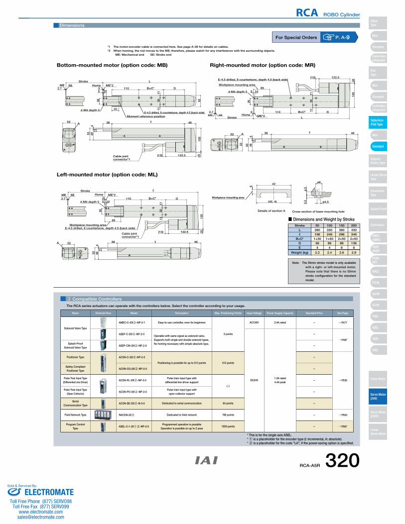
Cross section of base-mounting holeDetails of section A
3.5
ø8
ø4.5
4.5
(42. 4)
6
42
Workpiece mounting area
(13)
A
26
53
38
449
1011
1130
11
52
5
4-M4 depth 5 20
110
46
105
122.5 (2)
D
Stroke
3ME*2Home
2.7
LSEME
E-4.5 drilled, 8 counterbore, depth 4.5 (back side)
A
122.5
26
53
38
449
10
11
1130
11
(2)
54-M4 depth 5110 D
Stroke
3ME*2Home
2.7SEME
E-4.5 drilled, 8 counterbore, depth 4.5 (back side)
52
(13)
105
46
65
Workpiece mounting area
B×CP
B×CP
Cable jointconnector*1
Cable jointconnector*1
Workpiece mounting area65
53
46
105
(13)
52
E-4.5 drilled, 8 counterbore, depth 4.5 (back side)
ME SEL
2.7Home ME*2
3
Stroke
D110
4-M4 depth 5
5
(2)
1130
11
11
10
494
38
5326
122.5
A
B×CP
Bottom-mounted motor (option code: MB)
Left-mounted motor (option code: ML)
Right-mounted motor (option code: MR)
Moment reference position
52 ℓ
ℓ
ℓ
ℓ
Dimensions
*1 The motor-encoder cable is connected here. See page A-39 for details on cables.*2 When homing, the rod moves to the ME; therefore, please watch for any interference with the surrounding objects.
ME: Mechanical end SE: Stroke end
3 Compatible Controllers
The RCA series actuators can operate with the controllers below. Select the controller according to your usage.
For Special Orders P. A-9
Stroke 50 100 150 200
Lℓ
B×CP
DE
Weight (kg)
280196
1×30564
2.2
330246
1×50864
2.4
380296
2×50866
2.6
430346
2×50136
6
2.8
■ Dimensions and Weight by Stroke
Note: The 50mm stroke model is only available with a right- or left-mounted motor. Please note that there is no 50mm stroke configuration for the standard model.
* This is for the single-axis ASEL.* 1 is a placeholder for the encoder type (I: incremental, A: absolute). * 2 is a placeholder for the code "LA", if the power-saving option is specified.
Name External View Model Description Max. Positioning Points Input Voltage Power Supply Capacity Standard Price See Page
Solenoid Valve Type
AMEC-C-20I2-NP-2-1 Easy-to-use controller, even for beginners
3 points
AC100V 2.4A rated – → P477
ASEP-C-20I2-NP-2-0Operable with same signal as solenoid valve.Supports both single and double solenoid types.No homing necessary with simple absolute type.
DC24V1.3A rated4.4A peak
–
→ P487Splash-Proof
Solenoid Valve TypeASEP-CW-20I2-NP-2-0 –
Positioner Type ACON-C-20I2-NP-2-0
Positioning is possible for up to 512 points 512 points
–
→ P535
Safety-Compliant Positioner Type
ACON-CG-20I2-NP-2-0 –
Pulse Train Input Type(Differential Line Driver)
ACON-PL-20I2-NP-2-0Pulse train input type with
differential line driver support(−)
–
Pulse Train Input Type(Open Collector)
ACON-PO-20I2-NP-2-0Pulse train input type with
open collector support–
Serial Communication Type
ACON-SE-20I2-N-0-0 Dedicated to serial communication 64 points –
Field Network Type RACON-202 Dedicated to field network 768 points – → P503
Program Control Type
ASEL-C-1-2012-NP-2-0Programmed operation is possible
Operation is possible on up to 2 axes1500 points – → P567
RCA-A5R 320
RCA ROBO Cylinder
Mini
Mini
PSEP/ASEP
PMEC/AMEC
ROBONET
ERC2
PCON
ACON
SCON
PSEL
ASEL
SSEL
XSEL
Standard
Mini
Standard
Standard
ControllersIntegrated
ControllersIntegrated
SliderType
RodType
Table/Arm/Flat Type
Gripper/Rotary Type
Linear ServoType
Cleanroom Type
Splash Proof
Controllers
Pulse Motor
Servo Motor (24V)
Servo Motor (200V)
LinearServo Motor
ELECTROMATEToll Free Phone (877) SERVO98
Toll Free Fax (877) SERV099www.electromate.com
Sold & Serviced By:
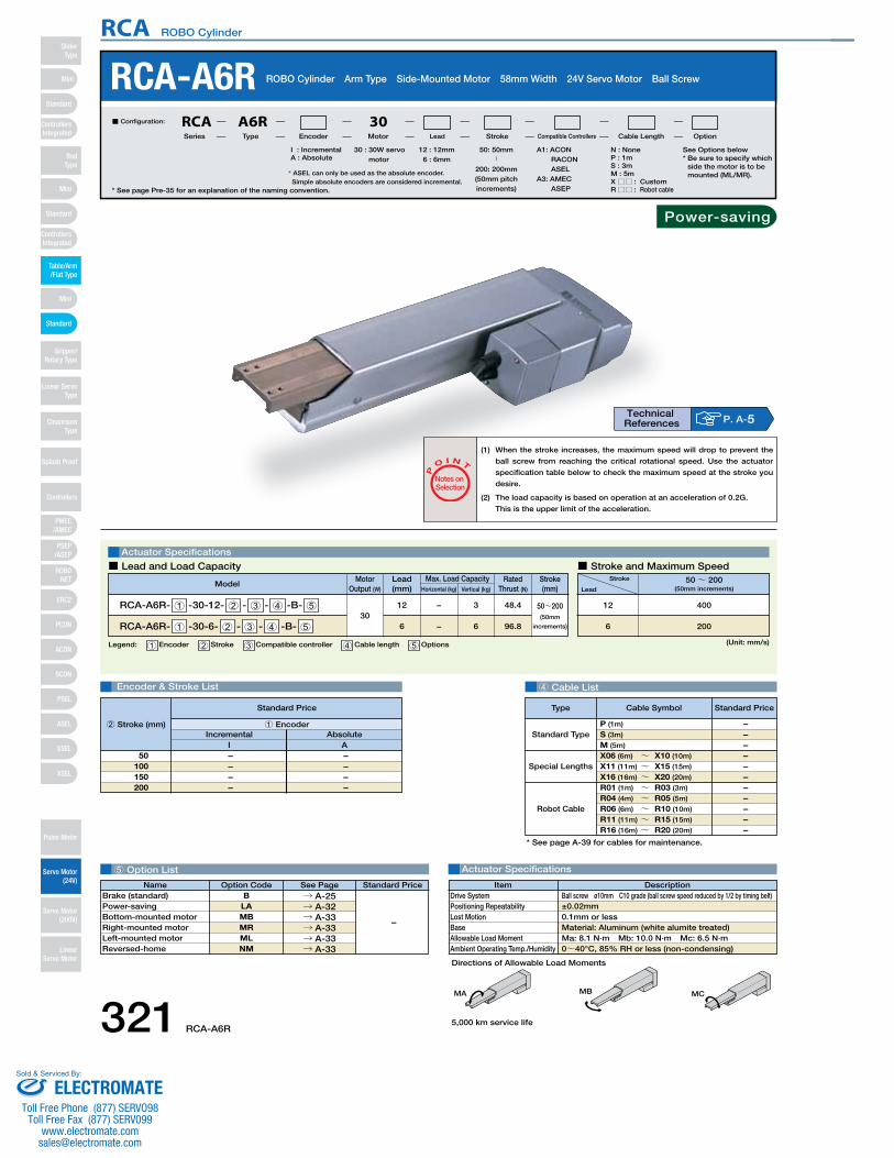
DescriptionItemBall screw ø10mm C10 grade (ball screw speed reduced by 1/2 by timing belt)±0.02mm0.1mm or lessMaterial: Aluminum (white alumite treated)Ma: 8.1 N∙m Mb: 10.0 N∙m Mc: 6.5 N∙m0~40°C, 85% RH or less (non-condensing)
Drive SystemPositioning RepeatabilityLost MotionBaseAllowable Load MomentAmbient Operating Temp./Humidity
SA4D : Aluminum
base
SS4D : Steel base
4 Cable List
5 Option List Actuator Specifications
RCA-A6R ROBO Cylinder Arm Type Side-Mounted Motor 58mm Width 24V Servo Motor Ball Screw
Actuator Specifications
■ Lead and Load Capacity ■ Stroke and Maximum Speed
P
O I N T
Notes on Selection
(1) When the stroke increases, the maximum speed will drop to prevent the
ball screw from reaching the critical rotational speed. Use the actuator
specification table below to check the maximum speed at the stroke you
desire.
(2) The load capacity is based on operation at an acceleration of 0.2G.
This is the upper limit of the acceleration.
30 : 30W servo motor
I : IncrementalA : Absolute
N : NoneP : 1mS : 3mM : 5mX □□ : CustomR□□ : Robot cable
See Options below* Be sure to specify which
side the motor is to be mounted (ML/MR).
50: 50mm〜
200: 200mm(50mm pitch increments)
12 : 12mm6 : 6mm
■ Configuration: RCA A6R 30Series Type Encoder Motor Lead Stroke Compatible Controllers Cable Length Option
Legend: 1 Encoder 2 Stroke 3 Compatible controller 4 Cable length 5 Options
Motor Output (W)
Lead(mm) Horizontal (kg) Vertical (kg)
Max. Load Capacity Rated Thrust (N)
ModelStroke(mm)
RCA-A6R- 1 -30-12- 2 - 3 - 4 -B- 5
RCA-A6R- 1 -30-6- 2 - 3 - 4 -B- 530
12
6
−
−
3
6
48.4
96.8
50~200(50mm
increments)
(Unit: mm/s)
Stroke
Lead50~ 200
(50mm increments)
400
200
12
6
Encoder & Stroke List
– – – –
– – – –
Incremental AbsoluteI
50100150200
A
Standard Price
1 Encoder2 Stroke (mm)
Special Lengths
Type Standard PriceCable Symbol
Standard Type
Robot Cable
P (1m)
S (3m)
M (5m)
X06 (6m) ~ X10 (10m)
X11 (11m) ~ X15 (15m)
X16 (16m) ~ X20 (20m)
R01 (1m) ~ R03 (3m)
R04 (4m) ~ R05 (5m)
R06 (6m) ~ R10 (10m)
R11 (11m) ~ R15 (15m)
R16 (16m) ~ R20 (20m)
– – – – – – – – – – –
* See page A-39 for cables for maintenance.
MA MB MC
* See page Pre-35 for an explanation of the naming convention.
P. A-5Technical References
Name Standard PriceOption Code See PageB
LAMBMRMLNM
→ A-25→ A-32→ A-33→ A-33→ A-33→ A-33
Brake (standard)Power-savingBottom-mounted motorRight-mounted motorLeft-mounted motorReversed-home
–
* ASEL can only be used as the absolute encoder.Simple absolute encoders are considered incremental.
Directions of Allowable Load Moments
Power-saving
5,000 km service life
A1: ACON RACON ASEL
A3: AMEC ASEP
321 RCA-A6R
RCA ROBO Cylinder
Mini
Mini
PSEP/ASEP
PMEC/AMEC
ROBONET
ERC2
PCON
ACON
SCON
PSEL
ASEL
SSEL
XSEL
Standard
Mini
Standard
Standard
ControllersIntegrated
ControllersIntegrated
RodType
Table/Arm/Flat Type
Gripper/Rotary Type
Linear ServoType
Cleanroom Type
Splash Proof
Controllers
Pulse Motor
Servo Motor (24V)
Servo Motor (200V)
LinearServo Motor
SliderType
ELECTROMATEToll Free Phone (877) SERVO98
Toll Free Fax (877) SERV099www.electromate.com
Sold & Serviced By:
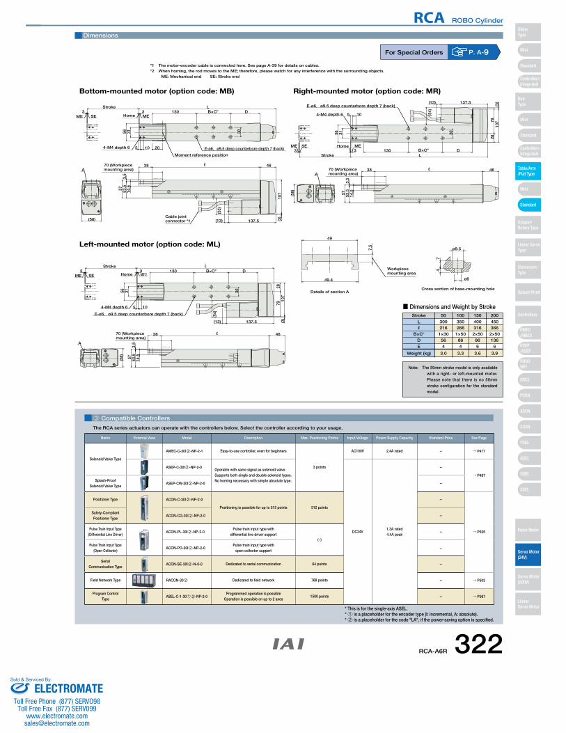
A
137.5 (3)
30
46
107
33
70 (Workpiece mounting area)
E-ø6,ø9.5 deep counterbore depth 7 (back)
Stroke L130 D
(13)
3.5
14.557 53.5
56 31
10 205
38
4-M4 depth 6
Cable jointconnector *1
HomeSEME ME
(58)
Cross section of base-mounting holeDetails of section A
Workpiece mounting area
49
7.5
49.4
74
ø9.5
ø6
A
30
33
70 (Workpiece mounting area)
E-ø6,ø9.5 deep counterbore depth 7 (back)
Stroke L130 D
ℓ
3.5
14.557 53.5
56 31
105
38
4-M4 depth 6
HomeSEME ME
(58)
2879
107
(3)137.5(13)
46
A
30
33
70 (Workpiece mounting area)
E-ø6,ø9.5 deep counterbore depth 7 (back)
Stroke ℓ130 D
3.5
14.557 53.5
56 31
105
38
4-M4 depth 6
HomeSEME ME*2
(58)
2879
107
(3)
137.5(13)
46
B×CP
B×CP
(53)
(54)
(54)
B×CP
Bottom-mounted motor (option code: MB)
Left-mounted motor (option code: ML)
Right-mounted motor (option code: MR)
Moment reference position
ℓ
ℓ
Dimensions
*1 The motor-encoder cable is connected here. See page A-39 for details on cables.*2 When homing, the rod moves to the ME; therefore, please watch for any interference with the surrounding objects.
ME: Mechanical end SE: Stroke end
3 Compatible Controllers
The RCA series actuators can operate with the controllers below. Select the controller according to your usage.
For Special Orders P. A-9
Stroke 50 100 150 200
Lℓ
B×CP
DE
Weight (kg)
300216
1×30564
3.0
350266
1×50864
3.3
400316
2×50866
3.6
450366
2×50136
6
3.9
■ Dimensions and Weight by Stroke
Note: The 50mm stroke model is only available with a right- or left-mounted motor. Please note that there is no 50mm stroke configuration for the standard model.
* This is for the single-axis ASEL.* 1 is a placeholder for the encoder type (I: incremental, A: absolute). * 2 is a placeholder for the code "LA", if the power-saving option is specified.
Name External View Model Description Max. Positioning Points Input Voltage Power Supply Capacity Standard Price See Page
Solenoid Valve Type
AMEC-C-30I2-NP-2-1 Easy-to-use controller, even for beginners
3 points
AC100V 2.4A rated – → P477
ASEP-C-30I2-NP-2-0Operable with same signal as solenoid valve.Supports both single and double solenoid types.No homing necessary with simple absolute type.
DC24V1.3A rated4.4A peak
–
→ P487Splash-Proof
Solenoid Valve TypeASEP-CW-30I2-NP-2-0 –
Positioner Type ACON-C-30I2-NP-2-0
Positioning is possible for up to 512 points 512 points
–
→ P535
Safety-Compliant Positioner Type
ACON-CG-30I2-NP-2-0 –
Pulse Train Input Type(Differential Line Driver)
ACON-PL-30I2-NP-2-0Pulse train input type with
differential line driver support(−)
–
Pulse Train Input Type(Open Collector)
ACON-PO-30I2-NP-2-0Pulse train input type with
open collector support–
Serial Communication Type
ACON-SE-30I2-N-0-0 Dedicated to serial communication 64 points –
Field Network Type RACON-302 Dedicated to field network 768 points – → P503
Program Control Type
ASEL-C-1-3012-NP-2-0Programmed operation is possible
Operation is possible on up to 2 axes1500 points – → P567
RCA-A6R 322
RCA ROBO Cylinder
Mini
Mini
PSEP/ASEP
PMEC/AMEC
ROBONET
ERC2
PCON
ACON
SCON
PSEL
ASEL
SSEL
XSEL
Standard
Mini
Standard
Standard
ControllersIntegrated
ControllersIntegrated
SliderType
RodType
Table/Arm/Flat Type
Gripper/Rotary Type
Linear ServoType
Cleanroom Type
Splash Proof
Controllers
Pulse Motor
Servo Motor (24V)
Servo Motor (200V)
LinearServo Motor
ELECTROMATEToll Free Phone (877) SERVO98
Toll Free Fax (877) SERV099www.electromate.com
Sold & Serviced By:
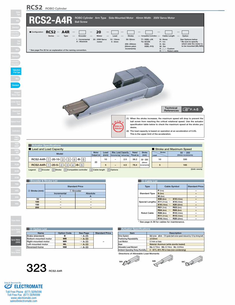
DescriptionItemBall screw ø8mm C10 grade (ball screw speed reduced by 1/2 by timing belt)±0.02mm0.1mm or lessMaterial: Aluminum (white alumite treated)Ma: 2.7 N∙m Mb: 3.1 N∙m Mc: 2.9 N∙m0~40°C, 85% RH or less (non-condensing)
Drive SystemPositioning RepeatabilityLost MotionBaseAllowable Load MomentAmbient Operating Temp./Humidity
4 Cable List
5 Option List Actuator Specifications
RCS2-A4R ROBO Cylinder Arm Type Side-Mounted Motor 40mm Width 200V Servo Motor
Ball Screw
Actuator Specifications
■ Lead and Load Capacity ■ Stroke and Maximum Speed
P
O I N T
Notes on Selection
(1) When the stroke increases, the maximum speed will drop to prevent the
ball screw from reaching the critical rotational speed. Use the actuator
specification table below to check the maximum speed at the stroke you
desire.
(2) The load capacity is based on operation at an acceleration of 0.2G.
This is the upper limit of the acceleration.
20 : 20W Servo motor
I : IncrementalA : Absolute
T1: XSEL-J/KT2: SCON
SSEL XSEL-P/Q
N : NoneP : 1mS : 3mM : 5mX □□ : CustomR□□ : Robot cable
50: 50mm〜
200: 200mm(50mm pitch increments)
10 : 10mm5 : 5mm
■ Configuration: RCS2 A4R 20Series Type Encoder Motor Lead Stroke Compatible Controllers Cable Length Option
Legend: 1 Encoder 2 Stroke 3 Compatible controller 4 Cable length 5 Options
Motor Output (W)
Lead(mm) Horizontal (kg) Vertical (kg)
Max. Load Capacity Rated Thrust (N)
ModelStroke(mm)
RCS2-A4R- 1 -20-10- 2 - 3 - 4 -B- 5
RCS2-A4R- 1 -20-5- 2 - 3 - 4 -B- 520
10
5
−
−
2.5
4.5
39.2
78.4
50~200(50mm
increments)
(Unit: mm/s)
Stroke
Lead50~ 200
(50mm increments)
330
165
10
5
Encoder & Stroke List
– – – –
– – – –
Incremental AbsoluteI
50100150200
A
Standard Price
1 Encoder2 Stroke (mm)
MA MB MC
Special Lengths
Type Standard PriceCable Symbol
Standard Type
Robot Cable
P (1m)
S (3m)
M (5m)
X06 (6m) ~ X10 (10m)
X11 (11m) ~ X15 (15m)
X16 (16m) ~ X20 (20m)
R01 (1m) ~ R03 (3m)
R04 (4m) ~ R05 (5m)
R06 (6m) ~ R10 (10m)
R11 (11m) ~ R15 (15m)
R16 (16m) ~ R20 (20m)
– – – – – – – – – – –
* See page A-39 for cables for maintenance.
* See page Pre-35 for an explanation of the naming convention.
Name Standard PriceOption Code See PageB
MBMRMLNM
→ A-25→ A-33→ A-33→ A-33→ A-33
Brake (standard) Bottom-mounted motorRight-mounted motorLeft-mounted motorReversed-home
–
P. A-5Technical References
Directions of Allowable Load Moments
See Options below* Be sure to specify
which side the motor is to be mounted (ML/MR).
323 RCS2-A4R
RCS2 ROBO Cylinder
Mini
Mini
PSEP/ASEP
PMEC/AMEC
ROBONET
ERC2
PCON
ACON
SCON
PSEL
ASEL
SSEL
XSEL
Standard
Mini
Standard
Standard
ControllersIntegrated
ControllersIntegrated
RodType
Table/Arm/Flat Type
Gripper/Rotary Type
Linear ServoType
Cleanroom Type
Splash Proof
Controllers
Pulse Motor
Servo Motor (24V)
Servo Motor (200V)
LinearServo Motor
SliderType
ELECTROMATEToll Free Phone (877) SERVO98
Toll Free Fax (877) SERV099www.electromate.com
Sold & Serviced By:
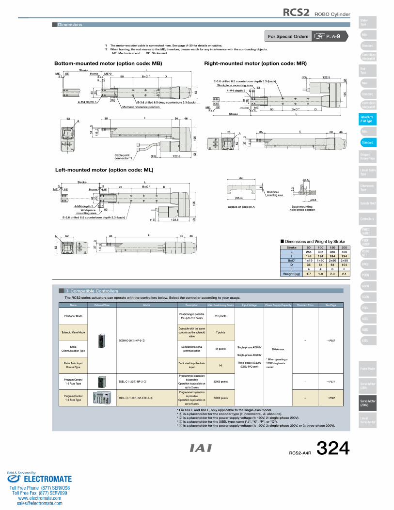
3 Compatible Controllers
The RCS2 series actuators can operate with the controllers below. Select the controller according to your usage.
Pulse Train Input Control Type
Program Control 1-6 Axes Type
SSEL-C-1-201-NP-2-2
XSEL-3-1-201-N1-EEE-2-4
Solenoid Valve Mode
Positioner ModePositioning is possible
for up to 512 points512 points
Single-phase AC100V
Single-phase AC200V
Three-phase AC200V(XSEL-P/Q only)
360VA max.
* When operating a 150W single-axis model
Operable with the same controls as the solenoid
valve7 points
Dedicated to serial communication
64 points
Dedicated to pulse train input
(−)
Programmed operation is possible
Operation is possible on up to 2 axes
Programmed operation is possible
Operation is possible on up to 6 axes
20000 points
20000 points
SCON-C-201-NP-2-2 → P547
→ P577
→ P587
–
–
–
Serial Communication Type
Program Control 1-2 Axes Type
Name External View Description Max. Positioning Points Input Voltage Power Supply CapacityModel See PageStandard Price
* For SSEL and XSEL, only applicable to the single-axis model.* 1 is a placeholder for the encoder type (I: incremental, A: absolute).* 2 is a placeholder for the power supply voltage (1: 100V, 2: single-phase 200V).* 3 is a placeholder for the XSEL type name ("J", "K", "P", or "Q").* 4 is a placeholder for the power supply voltage (1: 100V, 2: single-phase 200V, or 3: three-phase 200V).
For Special Orders P. A-9
(2)
4-M4 depth 5
ME SE ME*2Home
E-3.6 drilled 6.5 deep counterbore 3.3 (back)
3 3 D90
20 52
B×C P
5 10
3035
LStroke
4652
105
337
101.
5
A
122.5(13)
Moment reference position
16
Workpiece mounting area
ø3.6
ø6.5
2.25
33
(33.4)
Base mounting hole cross section
Details of section A
Workpiece mounting area53
52
(2)
4-M4 depth 5
40
33
Stroke L
122.5
Home ME
1.5
10
373
52 4635 30
105
90
105
20
D
E-3.6 drilled 6.5 counterbore depth 3.3 (back)
A
(13)
SEME
Workpiece mounting area
53
52
(2)
4-M4 depth 5
40
33Stroke L
122.5
Home ME
1.5
10
373
52 4635 30
105
90
105
20
D
E-3.6 drilled 6.5 counterbore depth 3.3 (back)
A
(13)
SEME
Bottom-mounted motor (option code: MB)
Left-mounted motor (option code: ML)
Right-mounted motor (option code: MR)
Cable jointconnector *1
40
ℓ
ℓ
ℓ
B×C P
B×C P
Dimensions
*1 The motor-encoder cable is connected here. See page A-39 for details on cables.*2 When homing, the rod moves to the ME; therefore, please watch for any interference with the surrounding objects.
ME: Mechanical end SE: Stroke end
Stroke 50 100 150 200
Lℓ
B×CP
DE
Weight (kg)
255144
1×19354
1.7
305194
1×50544
1.8
355244
2×50546
2.0
405294
2×50104
6
2.1
■ Dimensions and Weight by Stroke
RCS2-A4R 324
RCS2 ROBO Cylinder
Mini
Mini
PSEP/ASEP
PMEC/AMEC
ROBONET
ERC2
PCON
ACON
SCON
PSEL
ASEL
SSEL
XSEL
Standard
Mini
Standard
Standard
ControllersIntegrated
ControllersIntegrated
SliderType
RodType
Table/Arm/Flat Type
Gripper/Rotary Type
Linear ServoType
Cleanroom Type
Splash Proof
Controllers
Pulse Motor
Servo Motor (24V)
Servo Motor (200V)
LinearServo Motor
ELECTROMATEToll Free Phone (877) SERVO98
Toll Free Fax (877) SERV099www.electromate.com
Sold & Serviced By:
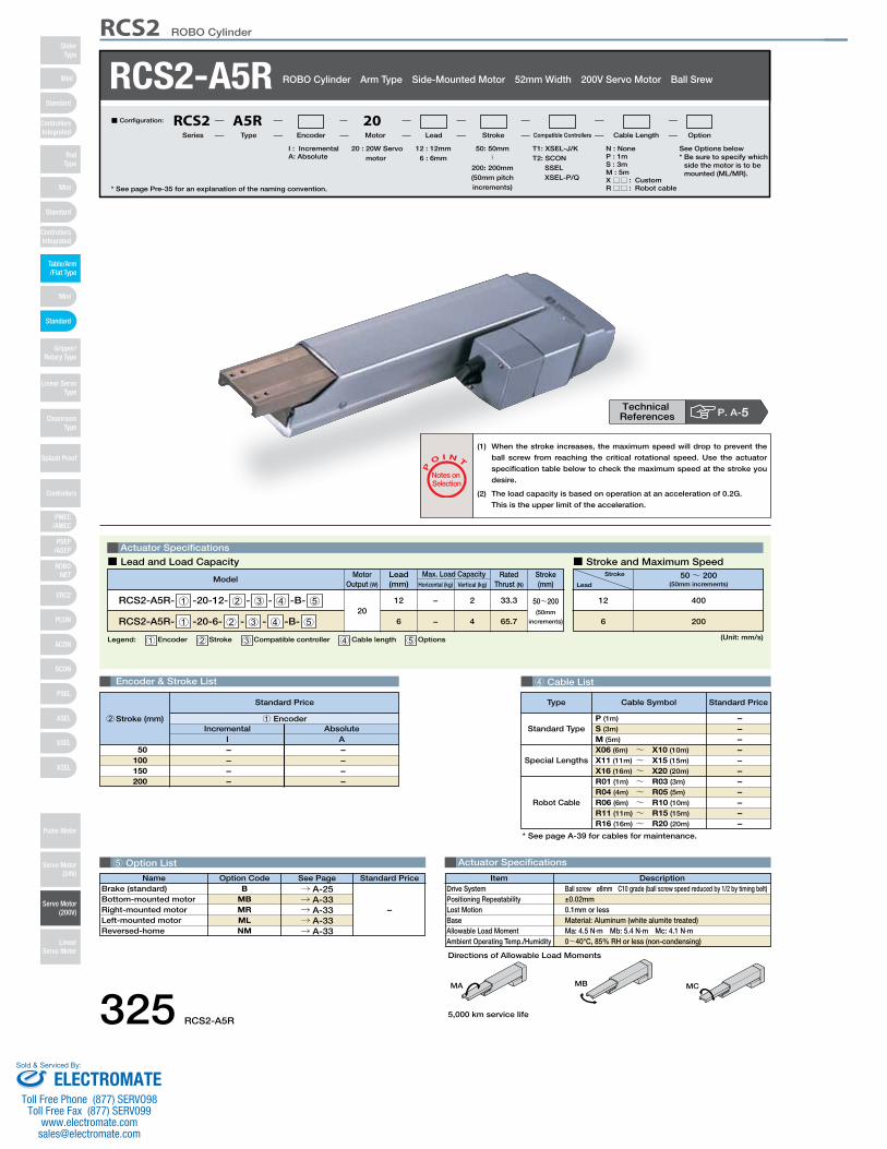
DescriptionItemBall screw ø8mm C10 grade (ball screw speed reduced by 1/2 by timing belt)±0.02mm0.1mm or lessMaterial: Aluminum (white alumite treated)Ma: 4.5 N∙m Mb: 5.4 N∙m Mc: 4.1 N∙m0~40°C, 85% RH or less (non-condensing)
Drive SystemPositioning RepeatabilityLost MotionBaseAllowable Load MomentAmbient Operating Temp./Humidity
4 Cable List
5 Option List Actuator Specifications
RCS2-A5R ROBO Cylinder Arm Type Side-Mounted Motor 52mm Width 200V Servo Motor Ball Srew
Actuator Specifications
■ Lead and Load Capacity ■ Stroke and Maximum Speed
P
O I N T
Notes on Selection
(1) When the stroke increases, the maximum speed will drop to prevent the
ball screw from reaching the critical rotational speed. Use the actuator
specification table below to check the maximum speed at the stroke you
desire.
(2) The load capacity is based on operation at an acceleration of 0.2G.
This is the upper limit of the acceleration.
20 : 20W Servo motor
I : IncrementalA: Absolute
T1: XSEL-J/KT2: SCON
SSELXSEL-P/Q
N : NoneP : 1mS : 3mM : 5mX □□ : CustomR□□ : Robot cable
50: 50mm〜
200: 200mm(50mm pitch increments)
12 : 12mm6 : 6mm
■ Configuration: RCS2 A5R 20Series Type Encoder Motor Lead Stroke Compatible Controllers Cable Length Option
Legend: 1 Encoder 2 Stroke 3 Compatible controller 4 Cable length 5 Options
Motor Output (W)
Lead(mm) Horizontal (kg) Vertical (kg)
Max. Load Capacity Rated Thrust (N)
ModelStroke(mm)
RCS2-A5R- 1 -20-12- 2 - 3 - 4 -B- 5
RCS2-A5R- 1 -20-6- 2 - 3 - 4 -B- 520
12
6
−
−
2
4
33.3
65.7
50~200(50mm
increments)
(Unit: mm/s)
Stroke
Lead50~ 200
(50mm increments)
400
200
12
6
Encoder & Stroke List
– – – –
– – – –
Incremental AbsoluteI
50100150200
A
Standard Price
1 Encoder2 Stroke (mm)
MA MB MC
Special Lengths
Type Standard PriceCable Symbol
Standard Type
Robot Cable
P (1m)
S (3m)
M (5m)
X06 (6m) ~ X10 (10m)
X11 (11m) ~ X15 (15m)
X16 (16m) ~ X20 (20m)
R01 (1m) ~ R03 (3m)
R04 (4m) ~ R05 (5m)
R06 (6m) ~ R10 (10m)
R11 (11m) ~ R15 (15m)
R16 (16m) ~ R20 (20m)
– – – – – – – – – – –
* See page A-39 for cables for maintenance.
* See page Pre-35 for an explanation of the naming convention.
Name Standard PriceOption Code See PageB
MBMRMLNM
→ A-25→ A-33→ A-33→ A-33→ A-33
Brake (standard) Bottom-mounted motorRight-mounted motorLeft-mounted motorReversed-home
–
P. A-5Technical References
Directions of Allowable Load Moments
See Options below* Be sure to specify which
side the motor is to be mounted (ML/MR).
5,000 km service life325 RCS2-A5R
RCS2 ROBO Cylinder
Mini
Mini
PSEP/ASEP
PMEC/AMEC
ROBONET
ERC2
PCON
ACON
SCON
PSEL
ASEL
SSEL
XSEL
Standard
Mini
Standard
Standard
ControllersIntegrated
ControllersIntegrated
RodType
Table/Arm/Flat Type
Gripper/Rotary Type
Linear ServoType
Cleanroom Type
Splash Proof
Controllers
Pulse Motor
Servo Motor (24V)
Servo Motor (200V)
LinearServo Motor
SliderType
ELECTROMATEToll Free Phone (877) SERVO98
Toll Free Fax (877) SERV099www.electromate.com
Sold & Serviced By:
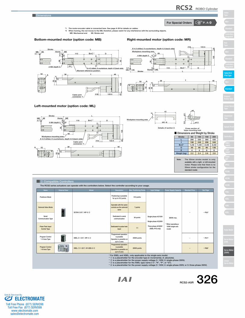
3 Compatible Controllers
The RCS2 series actuators can operate with the controllers below. Select the controller according to your usage.
Pulse Train Input Control Type
Program Control 1-6 Axes Type
SSEL-C-1-201-NP-2-2
XSEL-3-1-201-N1-EEE-2-4
Solenoid Valve Mode
Positioner ModePositioning is possible
for up to 512 points512 points
Single-phase AC100V
Single-phase AC200V
Three-phase AC200V(XSEL-P/Q only)
360VA max.
* When operating a 150W single-axis model
Operable with the same controls as the solenoid
valve7 points
Dedicated to serial communication
64 points
Dedicated to pulse train input
(−)
Programmed operation is possible
Operation is possible on up to 2 axes
Programmed operation is possible
Operation is possible on up to 6 axes
20000 points
20000 points
SCON-C-201-NP-2-2 → P547
→ P577
→ P587
–
–
–
Serial Communication Type
Program Control 1-2 Axes Type
Name External View Description Max. Positioning Points Input Voltage Power Supply CapacityModel See PageStandard Price
For Special Orders P. A-9
Cross section of base-mounting hole
Details of section A
3.5
ø8
ø4.5
4.5
(42. 4)
6
42
Workpiece mounting area
(13)
A52
26
53
38
449
1011
1130
11
52
5
4-M4 depth 5
110
46
105
122.5 (2)
D
Stroke
3MEHome
2.7
LSEME
E-4.5 drilled, 8 counterbore, depth 4.5 (back side)
A
122.5
26
53
38
449
10
11
1130
11
(2)
54-M4 depth 5110 D
Stroke
3MEHome
2.7
LSEME
E-4.5 drilled, 8 counterbore, depth 4.5 (back side)
52
(13)
105
46
65
Workpiece mounting area
B×C P
B×C P
Cable jointconnector *1
Cable jointconnector *1
Workpiece mounting area65
53
46
105
(13)
52
E-4.5 drilled, 8 counterbore, depth 4.5 (back side)
ME SEL
2.7Home ME
3
Stroke
D110
4-M4 depth 5
5
(2)
1130
11
11
10
494
38
5326
122.5
A
B×C P
Bottom-mounted motor (option code: MB)
Left-mounted motor (option code: ML)
Right-mounted motor (option code: MR)
20
Moment reference position
ℓ
ℓ
ℓ
Dimensions
*1 The motor-encoder cable is connected here. See page A-39 for details on cables.*2 When homing, the rod moves to the ME; therefore, please watch for any interference with the surrounding objects.
ME: Mechanical end SE: Stroke end
Stroke 50 100 150 200
Lℓ
B×CP
DE
Weight (kg)
280196
1×30564
2.2
330246
1×50864
2.4
380296
2×50866
2.6
430346
2×50136
6
2.8
■ Dimensions and Weight by Stroke
Note: The 50mm stroke model is only available with a right- or left-mounted motor. Please note that there is no 50mm stroke configuration for the standard model.
* For SSEL and XSEL, only applicable to the single-axis model.* 1 is a placeholder for the encoder type (I: incremental, A: absolute).* 2 is a placeholder for the power supply voltage (1: 100V, 2: single-phase 200V).* 3 is a placeholder for the XSEL type name ("J", "K", "P", or "Q").* 4 is a placeholder for the power supply voltage (1: 100V, 2: single-phase 200V, or 3: three-phase 200V).
RCS2-A5R 326
RCS2 ROBO Cylinder
Mini
Mini
PSEP/ASEP
PMEC/AMEC
ROBONET
ERC2
PCON
ACON
SCON
PSEL
ASEL
SSEL
XSEL
Standard
Mini
Standard
Standard
ControllersIntegrated
ControllersIntegrated
SliderType
RodType
Table/Arm/Flat Type
Gripper/Rotary Type
Linear ServoType
Cleanroom Type
Splash Proof
Controllers
Pulse Motor
Servo Motor (24V)
Servo Motor (200V)
LinearServo Motor
ELECTROMATEToll Free Phone (877) SERVO98
Toll Free Fax (877) SERV099www.electromate.com
Sold & Serviced By:

DescriptionItemBall screw ø10mm C10 grade (ball screw speed reduced by 1/2 by timing belt)±0.02mm0.1mm or lessMaterial: Aluminum (white alumite treated)Ma: 8.1 N∙m Mb: 10.0 N∙m Mc: 6.5 N∙m0~40°C, 85% RH or less (non-condensing)
Drive SystemPositioning RepeatabilityLost MotionBaseAllowable Load MomentAmbient Operating Temp./Humidity
SA4D
: Aluminum
base
SS4D : Steel
4 Cable List
5 Option List Actuator Specifications
RCS2-A6R ROBO Cylinder Arm Type Side-Mounted Motor 58mm Width 200V Servo Motor Ball Srew
Actuator Specifications
■ Lead and Load Capacity ■ Stroke and Maximum Speed
P
O I N T
Notes on Selection
(1) When the stroke increases, the maximum speed will drop to prevent the
ball screw from reaching the critical rotational speed. Use the actuator
specification table below to check the maximum speed at the stroke you
desire.
(2) The load capacity is based on operation at an acceleration of 0.2G.
This is the upper limit of the acceleration.
30 : 30W Servo motor
I : IncrementalA: Absolute
T1: XSEL-J/KT2: SCON
SSELXSEL-P/Q
N : NoneP : 1mS : 3mM : 5mX □□ : CustomR□□ : Robot cable
50: 50mm〜
200: 200mm(50mm pitch increments)
12 : 12mm6 : 6mm
■ Configuration: RCS2 A6R 30Series Type Encoder Motor Lead Stroke Compatible Controllers Cable Length Option
Legend: 1 Encoder 2 Stroke 3 Compatible controller 4 Cable length 5 Options
Motor Output (W)
Lead(mm) Horizontal (kg) Vertical (kg)
Max. Load Capacity Rated Thrust (N)
ModelStroke(mm)
RCS2-A6R- 1 -30-12- 2 - 3 - 4 -B- 5
RCS2-A6R- 1 -30-6- 2 - 3 - 4 -B- 530
12
6
−
−
3
6
48.4
96.8
50~200(50mm
increments)
(Unit: mm/s)
Stroke
Lead50~ 200
(50mm increments)
400
200
12
6
Encoder & Stroke List
– – – –
– – – –
Incremental AbsoluteI
50100150200
A
Standard Price
1 Encoder2 Stroke (mm)
MA MB MC
Special Lengths
Type Standard PriceCable Symbol
Standard Type
Robot Cable
P (1m)
S (3m)
M (5m)
X06 (6m) ~ X10 (10m)
X11 (11m) ~ X15 (15m)
X16 (16m) ~ X20 (20m)
R01 (1m) ~ R03 (3m)
R04 (4m) ~ R05 (5m)
R06 (6m) ~ R10 (10m)
R11 (11m) ~ R15 (15m)
R16 (16m) ~ R20 (20m)
– – – – – – – – – – –
* See page A-39 for cables for maintenance.
* See page Pre-35 for an explanation of the naming convention.
Name Standard PriceOption Code See PageB
MBMRMLNM
→ A-25→ A-33→ A-33→ A-33→ A-33
Brake (standard) Bottom-mounted motorRight-mounted motorLeft-mounted motorReversed-home
–
P. A-5Technical References
Directions of Allowable Load Moments
See Options below* Be sure to specify
which side the motor is to be mounted (ML/MR).
5,000 km service life327 RCS2-A6R
RCS2 ROBO Cylinder
Mini
Mini
PSEP/ASEP
PMEC/AMEC
ROBONET
ERC2
PCON
ACON
SCON
PSEL
ASEL
SSEL
XSEL
Standard
Mini
Standard
Standard
ControllersIntegrated
ControllersIntegrated
RodType
Table/Arm/Flat Type
Gripper/Rotary Type
Linear ServoType
Cleanroom Type
Splash Proof
Controllers
Pulse Motor
Servo Motor (24V)
Servo Motor (200V)
LinearServo Motor
SliderType
ELECTROMATEToll Free Phone (877) SERVO98
Toll Free Fax (877) SERV099www.electromate.com
Sold & Serviced By:
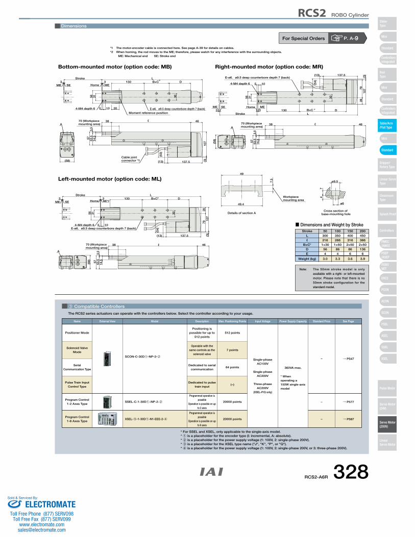
3 Compatible Controllers
The RCS2 series actuators can operate with the controllers below. Select the controller according to your usage.
For Special Orders P. A-9
A
137.5 (3)
30
46
107
33
70 (Workpiece mounting area)
E-ø6,ø9.5 deep counterbore depth 7 (back)
Stroke L130 D
(13)
3.5
14.557 53.5
56 31
105
38
HomeSEME ME
(58)
Cross section of base-mounting holeDetails of section A
Workpiece mounting area
49
7.5
49.4
74
ø9.5
ø6
A
30
33
70 (Workpiece mounting area)
E-ø6,ø9.5 deep counterbore depth 7 (back)
Stroke L130 D
3.5
14.557 53.5
56 31
105
38
4-M4 depth 6
HomeSEME ME
(58)
2879
107
(3)137.5(13)
46
A
30
33
70 (Workpiece mounting area)
E-ø6,ø9.5 deep counterbore depth 7 (back)
Stroke L130 D
3.5
14.557 53.5
56 31
105
38
4-M4 depth 6
HomeSEME ME*2
(58)
2879
107
(3)
137.5(13)
46
PB×C
B×CP
(53)
(54)
(54)
B×C P
Bottom-mounted motor (option code: MB)
Left-mounted motor (option code: ML)
Right-mounted motor (option code: MR)
204-M4 depth 6
Moment reference position
ℓ
ℓ
ℓ
Cable jointconnector *1
Dimensions
*1 The motor-encoder cable is connected here. See page A-39 for details on cables.*2 When homing, the rod moves to the ME; therefore, please watch for any interference with the surrounding objects.
ME: Mechanical end SE: Stroke end
Stroke 50 100 150 200
Lℓ
B×CP
DE
Weight (kg)
300216
1×30564
3.0
350266
1×50864
3.3
400316
2×50866
3.6
450366
2×50136
6
3.9
■ Dimensions and Weight by Stroke
Pulse Train Input Control Type
Program Control 1-6 Axes Type
SSEL-C-1-30D1-NP-2-2
XSEL-3-1-30D1-N1-EEE-2-4
Solenoid Valve Mode
Positioner ModePositioning is
possible for up to 512 points
512 points
Single-phase AC100V
Single-phase AC200V
Three-phase AC200V
(XSEL-P/Q only)
360VA max.
* When operating a 150W single-axis model
Operable with the same controls as the
solenoid valve7 points
Dedicated to serial communication
64 points
Dedicated to pulse train input
(−)
Programmed operation is possible
Operation is possible on up to 2 axes
Programmed operation is possible
Operation is possible on up to 6 axes
20000 points
20000 points
SCON-C-30D1-NP-2-2→ P547
→ P577
→ P587
–
–
–
Serial Communication Type
Program Control1-2 Axes Type
Name External View Description Max. Positioning Points Input Voltage Power Supply CapacityModel See PageStandard Price
Note: The 50mm stroke model is only available with a right- or left-mounted motor. Please note that there is no 50mm stroke configuration for the standard model.
* For SSEL and XSEL, only applicable to the single-axis model.* 1 is a placeholder for the encoder type (I: incremental, A: absolute).* 2 is a placeholder for the power supply voltage (1: 100V, 2: single-phase 200V).* 3 is a placeholder for the XSEL type name ("J", "K", "P", or "Q").* 4 is a placeholder for the power supply voltage (1: 100V, 2: single-phase 200V, or 3: three-phase 200V).
RCS2-A6R 328
RCS2 ROBO Cylinder
Mini
Mini
PSEP/ASEP
PMEC/AMEC
ROBONET
ERC2
PCON
ACON
SCON
PSEL
ASEL
SSEL
XSEL
Standard
Mini
Standard
Standard
ControllersIntegrated
ControllersIntegrated
SliderType
RodType
Table/Arm/Flat Type
Gripper/Rotary Type
Linear ServoType
Cleanroom Type
Splash Proof
Controllers
Pulse Motor
Servo Motor (24V)
Servo Motor (200V)
LinearServo Motor
ELECTROMATEToll Free Phone (877) SERVO98
Toll Free Fax (877) SERV099www.electromate.com
Sold & Serviced By:
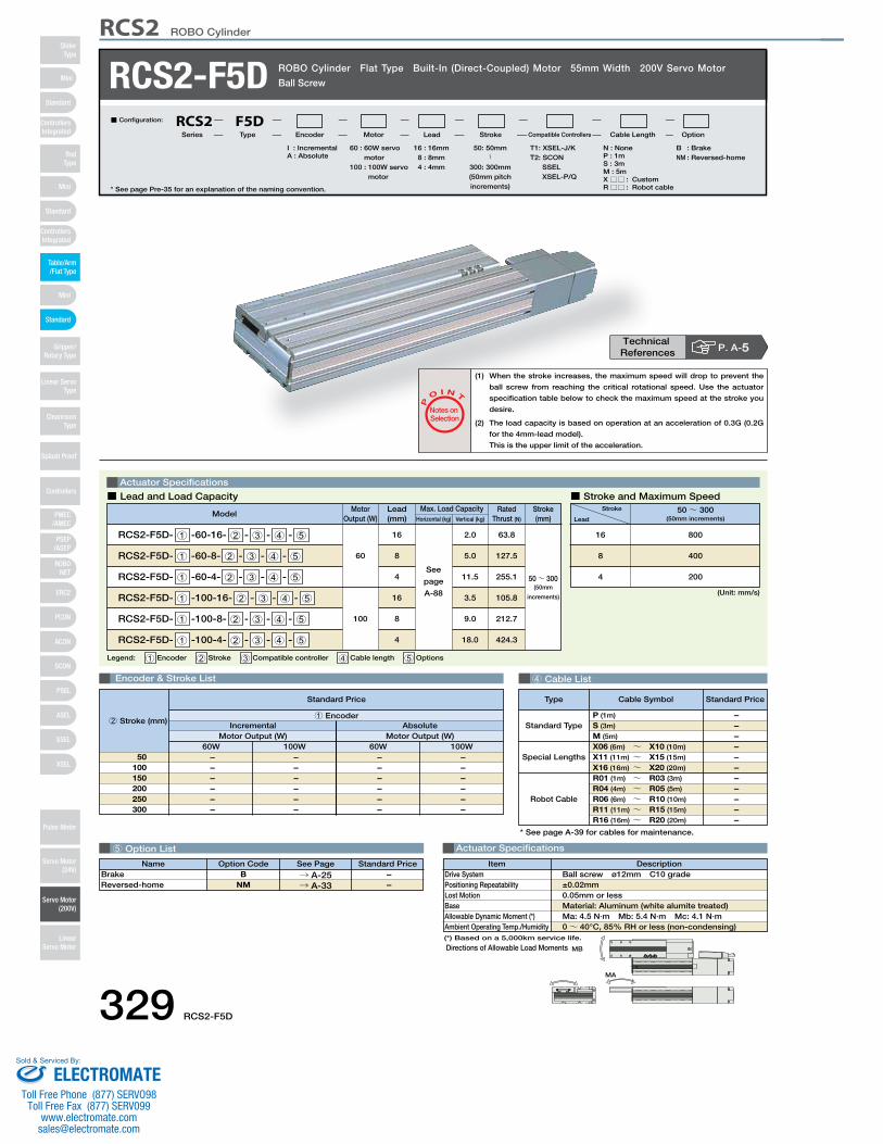
SA4D : Aluminum
base
SS4D : Steel base
Name Standard PriceOption Code See PageB
NM→ A-25→ A-33
BrakeReversed-home
– –
4 Cable List
5 Option List Actuator Specifications
RCS2-F5D ROBO Cylinder Flat Type Built-In (Direct-Coupled) Motor 55mm Width 200V Servo Motor
Ball Screw
Legend: 1 Encoder 2 Stroke 3 Compatible controller 4 Cable length 5 Options
Actuator Specifications
■ Lead and Load Capacity ■ Stroke and Maximum Speed
P
O I N T
Notes on Selection
(1) When the stroke increases, the maximum speed will drop to prevent the
ball screw from reaching the critical rotational speed. Use the actuator
specification table below to check the maximum speed at the stroke you
desire.
(2) The load capacity is based on operation at an acceleration of 0.3G (0.2G
for the 4mm-lead model).
This is the upper limit of the acceleration.
60 : 60W servo motor
100 : 100W servo motor
I : IncrementalA : Absolute
T1: XSEL-J/KT2: SCON
SSELXSEL-P/Q
N : NoneP : 1mS : 3mM : 5mX □□ : CustomR□□ : Robot cable
B : Brake NM : Reversed-home
50: 50mm〜
300: 300mm(50mm pitch increments)
16 : 16mm8 : 8mm4 : 4mm
■ Configuration: RCS2 F5DSeries Type Encoder Motor Lead Stroke Compatible Controllers Cable Length Option
(Unit: mm/s)
Stroke
Lead50~ 300
(50mm increments)
800
400
200
16
8
4
Encoder & Stroke List
– – – – – –
– – – – – –
– – – – – –
– – – – – –
IncrementalMotor Output (W)
AbsoluteMotor Output (W)
60W 100W 60W 100W50
100150200250300
Standard Price
1 Encoder2 Stroke (mm)
Motor Output (W)
Lead(mm) Horizontal (kg) Vertical (kg)
Max. Load Capacity Rated Thrust (N)
ModelStroke(mm)
RCS2-F5D- 1 -60-16- 2 - 3 - 4 - 5
RCS2-F5D- 1 -60-8- 2 - 3 - 4 - 5
RCS2-F5D- 1 -60-4- 2 - 3 - 4 - 5
RCS2-F5D- 1 -100-16- 2 - 3 - 4 - 5
RCS2-F5D- 1 -100-8- 2 - 3 - 4 - 5
RCS2-F5D- 1 -100-4- 2 - 3 - 4 - 5
60
100
16
8
4
16
8
4
See
page
A-88
2.0
5.0
11.5
3.5
9.0
18.0
63.8
127.5
255.1
105.8
212.7
424.3
50~ 300(50mm
increments)
MB
MA
* See page Pre-35 for an explanation of the naming convention.
Special Lengths
Type Standard PriceCable Symbol
Standard Type
Robot Cable
P (1m)
S (3m)
M (5m)
X06 (6m) ~ X10 (10m)
X11 (11m) ~ X15 (15m)
X16 (16m) ~ X20 (20m)
R01 (1m) ~ R03 (3m)
R04 (4m) ~ R05 (5m)
R06 (6m) ~ R10 (10m)
R11 (11m) ~ R15 (15m)
R16 (16m) ~ R20 (20m)
– – – – – – – – – – –
* See page A-39 for cables for maintenance.
Technical References P. A-5
DescriptionItemBall screw ø12mm C10 grade±0.02mm0.05mm or lessMaterial: Aluminum (white alumite treated)Ma: 4.5 N∙m Mb: 5.4 N∙m Mc: 4.1 N∙m0~ 40°C, 85% RH or less (non-condensing)
Drive SystemPositioning RepeatabilityLost MotionBaseAllowable Dynamic Moment (*)Ambient Operating Temp./Humidity
Directions of Allowable Load Moments(*) Based on a 5,000km service life.
329 RCS2-F5D
RCS2 ROBO Cylinder
Mini
Mini
PSEP/ASEP
PMEC/AMEC
ROBONET
ERC2
PCON
ACON
SCON
PSEL
ASEL
SSEL
XSEL
Standard
Mini
Standard
Standard
ControllersIntegrated
ControllersIntegrated
RodType
Table/Arm/Flat Type
Gripper/Rotary Type
Linear ServoType
Cleanroom Type
Splash Proof
Controllers
Pulse Motor
Servo Motor (24V)
Servo Motor (200V)
LinearServo Motor
SliderType
ELECTROMATEToll Free Phone (877) SERVO98
Toll Free Fax (877) SERV099www.electromate.com
Sold & Serviced By:
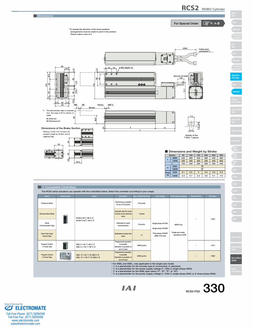
5 5
SEME ME*2HomeStroke
116
1.5
58 44
5 20 20
5512.5 30 12.5
12.5
3043
30.5
116
12.5
30
5619.2
71.7
6-M4 depth 12
581.
51.
512
.5
45.2
540.
554
Dimensions of the Brake Section
Cable jointconnector*1
(300)
54
Secure at least100
Details of theT-Slot, 7 places
4.3
7.3
1.5
4.5
ℓ m3L
36.856
Dimensions
* To change the direction of the home position,arrangements must be made to send in the product.Please make a note of it.
*1: The motor-encoder cable is connected here. See page A-39 for details on cables.
SE: Stroke endME: Mechanical end
* Adding a brake wi l l increase the actuator's length by 45.2mm, and its weight by 0.4kg.
■ Dimensions and Weight by StrokeStroke 50 100 150 200 250 300
Weight(kg)
ℓ
L
m
60W100W
60W100W
60W
100W
232250150
2.1
2.3
282300200
2.5
2.7
332350250
3
3.2
382400300
3.4
3.6
432450350
3.9
4.1
482500400
4.3
4.5
7997
For Special Order P. A-9
3 Compatible Controllers
The RCS2 series actuators can operate with the controllers below. Select the controller according to your usage.
Pulse Train Input Control Type
Program Control 1-6 Axes Type
SSEL-C-1-60 1-NP-2-2SSEL-C-1-100 1-NP-2-2
XSEL-3-1-60 1-N1-EEE-2-4XSEL-3-1-100 1-N1-EEE-2-4
Solenoid Valve Mode
Positioner ModePositioning is possible
for up to 512 points512 points
Single-phase AC100V
Single-phase AC200V
Three-phase AC200V(XSEL-P/Q only)
360VA max.
* Single-axis modeloperated at 150W
Operable with the same controls as the solenoid
valve7 points
Dedicated to serial communication
64 points
Dedicated to pulse train input
(−)
Programmed operation is possible
Operation is possible on up to 2 axes
Programmed operation is possible
Operation is possible on up to 6 axes
20000 points
20000 points
SCON-C-601-NP-2-2SCON-C-1001-NP-2-2
→ P547
→ P577
→ P587
–
–
–
Serial Communication Type
Program Control 1-2 Axes Type
Name External View Description Max. Positioning Points Input Voltage Power Supply CapacityModel See PageStandard Price
* For SSEL and XSEL, only applicable to the single-axis model.* 1 is a placeholder for the encoder type (I: incremental, A: absolute).* 2 is a placeholder for the power supply voltage (1: 100V, 2: single-phase 200V).* 3 is a placeholder for the XSEL type name ("J", "K", "P", or "Q").* 4 is a placeholder for the power supply voltage (1: 100V, 2: single-phase 200V, or 3: three-phase 200V).
RCS2-F5D 330
RCS2 ROBO Cylinder
Mini
Mini
PSEP/ASEP
PMEC/AMEC
ROBONET
ERC2
PCON
ACON
SCON
PSEL
ASEL
SSEL
XSEL
Standard
Mini
Standard
Standard
ControllersIntegrated
ControllersIntegrated
SliderType
RodType
Table/Arm/Flat Type
Gripper/Rotary Type
Linear ServoType
Cleanroom Type
Splash Proof
Controllers
Pulse Motor
Servo Motor (24V)
Servo Motor (200V)
LinearServo Motor
ELECTROMATEToll Free Phone (877) SERVO98
Toll Free Fax (877) SERV099www.electromate.com
Sold & Serviced By: