Embed Size (px)
Citation preview

SYNCHRONOUS GENERATOR
J.Majumder MIE Senior Faculty

SYNCHRONOUS GENERATOR
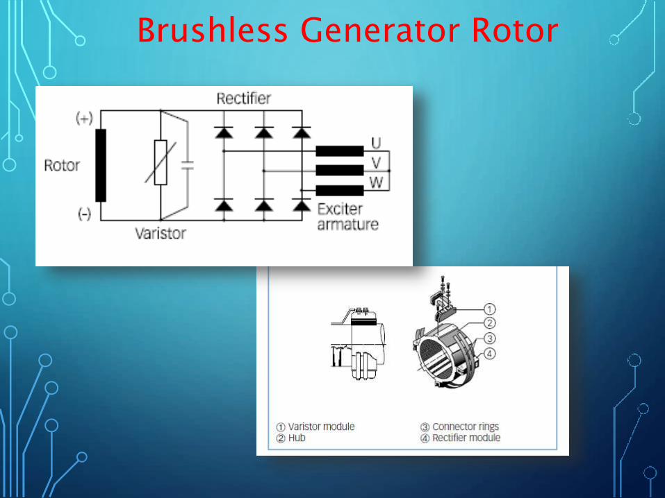
Brushless Generator Rotor

PARTS OF THE ROTOR


Brushless Generator Excitation

ROTARY EXCITER BRUSHLESS SYSTEM
CT
G
K L
K L
SPACE HEATER
A.C. GENERATOR
F1S1
Sil
Ex
FzJK
Rc
Sz
Siz
RT
H1
H2
H1
H2
R
S
T
R
S
T
3A
4A
3A
4A
T1S1R1A
BAVR
123
CW
RISE
VR
CCRACB
AUX. CONT
DCT
k l
k l k l
K LCCT
l1k1 l2k2
kl
R
S
T
AC 1
SWITCH BOARD

VOLTAGE BUILD UP IN BRUSHLESS GENERATOR
An unloaded generator builds up voltage due to residual voltage in the winding .Star connected Reactor coil L2 is only the load of the generator. The inductivecurrent which appears in the reactor coil will appear in primary winding P1.
This current willinduce current
In secondarywinding S
Field

Connection diagram of Generator

AVR
The actual function of the
voltage regulator is to provide
a bypass for a variable portion
of the current supplied by the
excitation equipment for
controlling the generator
voltage.
The thyristor regulator module
consists of two assemblies:
the regulator module and the
firing module with thyristor in buck circuit.
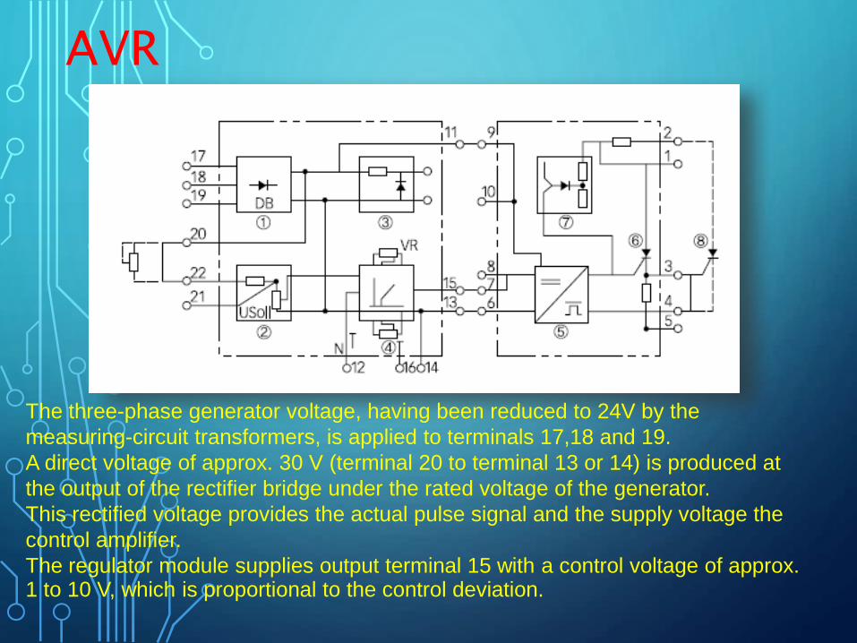
AVR
The three-phase generator voltage, having been reduced to 24V by the
measuring-circuit transformers, is applied to terminals 17,18 and 19.
A direct voltage of approx. 30 V (terminal 20 to terminal 13 or 14) is produced at
the output of the rectifier bridge under the rated voltage of the generator.
This rectified voltage provides the actual pulse signal and the supply voltage the
control amplifier.
The regulator module supplies output terminal 15 with a control voltage of approx. 1 to 10 V, which is proportional to the control deviation.

AVR
In the control circuit of the firing module, a time adjustable firing impulse for the
thyristor is formed from the control voltage of terminal 15 in comparison with a
saw tooth voltage. The overvoltage protector operates at voltages over
600 V between terminals 1 and 5, then switches the thyristor through.
The excitation current is normally bucked with a single pulse.
If higher excitation is required, two firing modules for two pulse "buck" operation will be provided.
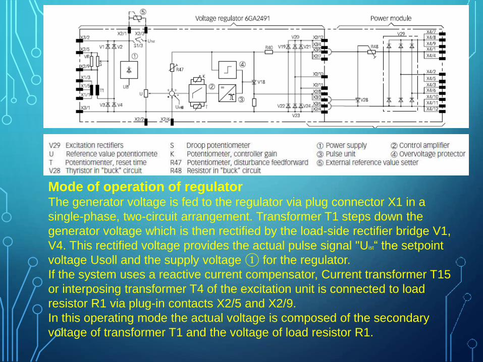
Mode of operation of regulatorThe generator voltage is fed to the regulator via plug connector X1 in a
single-phase, two-circuit arrangement. Transformer T1 steps down the
generator voltage which is then rectified by the load-side rectifier bridge V1,
V4. This rectified voltage provides the actual pulse signal "Uist“ the setpoint
voltage Usoll and the supply voltage ① for the regulator.
If the system uses a reactive current compensator, Current transformer T15
or interposing transformer T4 of the excitation unit is connected to load
resistor R1 via plug-in contacts X2/5 and X2/9.
In this operating mode the actual voltage is composed of the secondary
voltage of transformer T1 and the voltage of load resistor R1.
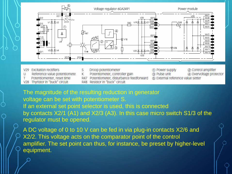
The magnitude of the resulting reduction in generator
voltage can be set with potentiometer S.
If an external set point selector is used, this is connected
by contacts X2/1 (A1) and X2/3 (A3). In this case micro switch S1/3 of the regulator must be opened.
A DC voltage of 0 to 10 V can be fed in via plug-in contacts X2/6 and
X2/2. This voltage acts on the comparator point of the control
amplifier. The set point can thus, for instance, be preset by higher-levelequipment.
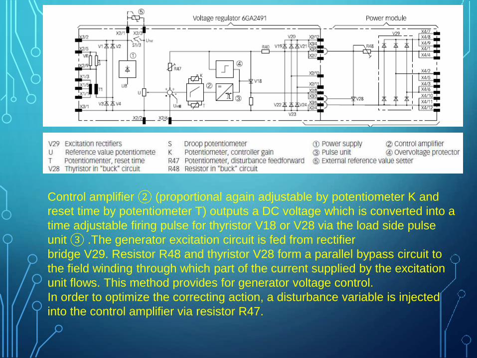
Control amplifier ② (proportional again adjustable by potentiometer K and
reset time by potentiometer T) outputs a DC voltage which is converted into a
time adjustable firing pulse for thyristor V18 or V28 via the load side pulse
unit ③ .The generator excitation circuit is fed from rectifier
bridge V29. Resistor R48 and thyristor V28 form a parallel bypass circuit to
the field winding through which part of the current supplied by the excitation
unit flows. This method provides for generator voltage control.
In order to optimize the correcting action, a disturbance variable is injected
into the control amplifier via resistor R47.

Regulator gain, set point voltage integral action
The control module comprises potentiometers U, K, T, R 47 and S.
The rated generator voltage has been adjusted by potentiometer U, and the dynamic behaviour of the regulator on potentiometers K, T and R 47.
Potentiometer K is used to adjust the controller gain and potentiometer T is
used to adjust the integral action time, whereas potentiometer R 47 is used
to inject a disturbance variable into the comparator point of the control
amplifier in order to adjust dynamic behaviour.
Turning the knob of K and R 47 in the direction of descending numerals and
that of T in the direction of ascending numerals normally stabilizes the
control circuit and reduces the control rate.

Voltage Droop
When the generator is operating by itself, the thyristor
voltage regulator controls the generator voltage to the
preset reference value.
Frequency changes due to the droop characteristics of the
prime mover do not influence the accuracy of the generator output voltage.

Parallel operation by droop compensation equipment
Droop compensating equipment ensures uniform distribution of the reactive
power and reduces the generator output voltage in linear with the increase in
reactive current.
Regarding generators with current transformer for droop compensation,
potentiometer S in the regulator is adjusted so that there is no reduction in the generator voltage at unity p.f. but a 4% reduction at zero p.f.


![WECC Data Preparation Manual with BCCS - MOD … · Web view2 = generator bus (voltage control [terminal or remote] within generator limits) 2 = generator bus with unlimited reactive](https://img.pdfslide.us/doc/110x75/5e7141d2f546c431ac535587/wecc-data-preparation-manual-with-bccs-mod-web-view-2-generator-bus-voltage.jpg)