Embed Size (px)
Citation preview
International Journal of Fuzzy Logic Systems (IJFLS) Vol.6, No.1, January 2016
DOI : 10.5121/ijfls.2016.6101 1
FUZZY LOGIC CONTROL OF A HYBRID ENERGY
STORAGE MODULE FOR NAVAL PULSED POWER
APPLICATIONS
Isaac Cohen
1, David Wetz
1, Stepfanie Veiga
2, Qing Dong
2, and John Heinzel
2
1Electrical Engineering Department, University of Texas at Arlington, Arlington, USA
2Naval Surface Warfare Center, Philadelphia Division, Philadelphia, USA
ABSTRACT
There is need for an energy storage device capable of transferring high power in transient situations
aboard naval vessels. Currently, batteries are used to accomplish this task, but previous research has
shown that when utilized at high power rates, these devices deteriorate over time causing a loss in lifespan.
It has been shown that a hybrid energy storage configuration is capable of meeting such a demand while
reducing the strain placed on individual components. While designing a custom converter capable of
controlling the power to and from a battery would be ideal for this application, it can be costly to develop
when compared to purchasing commercially available products. Commercially available products offer
limited controllability in exchange for their proven performance and lower cost point - often times only
allowing a system level control input without any way to interface with low level controls that are
frequently used in controller design. This paper proposes the use of fuzzy logic control in order to provide
a system level control to the converters responsible for limiting power to and from the battery. A system
will be described mathematically, modeled in MATLAB/Simulink, and a fuzzy logic controller will be
compared with a typical controller.
KEYWORDS
hybrid energy storage, power electronics, fuzzy logic control, power buffer, pulsed power loads
1. INTRODUCTION
The development of shipboard electrical systems continues to grow as the Navy plans to utilize
more electrical components than previously seen. With this growth comes a new electrical load
profile not commonly seen aboard ships. The addition of new directed energy based weapons as
well as electric propulsion give the ship a load profile that is more transient in nature than would
typically be seen. Traditionally, power generation sources would be fossil fuel driven generators,
but such a configuration would result in very poor performance and power quality if used to drive
the transient load profiles envisioned for the future [1].
Previous research has shown that energy storage devices (ESDs) are capable at compensating the
stochastic and intermittent nature of these power demands by absorbing the excessive energy
when generation exceeds predicted levels and providing energy back to the power system
network when generation levels fail to meet the demand. These ESDs are an essential component
to future power systems when integrating variable energy resources and stochastic pulsed loads.
Previous work has shown that Hybrid Energy Storage Modules (HESMs) can contribute to not
only improve the performance of an ESD, but also overcome the limitations of the individual

International Journal of Fuzzy Logic Systems (IJFLS) Vol.6, No.1, January 2016
2
components of the architecture, such as the power delivery limitations of a battery or the energy
storage limitations of an ultracapacitor [2, 3, 4]. While this topology has been verified, there are
still some questions on how to best control them. [5] designed a low cost digital energy
management system and an optimal control algorithm was developed in [6] to coordinate slow
ESDs and fast ESDs. While these control developments have been very useful, they do not
address the need for a controller that is capable of interfacing with Commercial-Off-The-Shelf
(COTS) products. Fuzzy logic control has been used in many applications such as [7], who
developed an intuitive fuzzy logic based learning algorithm which was implemented to reduce
intensive computation of a complex dynamics such as a humanoid. Some, such as [8] have
utilized fuzzy logic control to drive a HESM, but in their case, they used the controller in order to
eliminate the need to constantly calculate resource intensive Riccati equations to assist in
choosing gains for an adaptive Linear-Quadratic Regulator controller. Others, such as [9, 10]
developed an energy-based split and power sharing control strategy for hybrid energy storage
systems, but these strategies are focused on different target variables such as loss reduction,
leveling the components state of charge, or optimizing system operating points in a vehicular
system.
When constructing a HESM for naval pulsed power load applications, several design parameters
must be considered to develop the controller. First, the HESM must be responsible for supplying
all load demands that it might encounter. Energy sizing techniques such as shown in [11] should
be applied in order to assist in meeting this demand. Second, the HESM should add the benefit of
becoming an additional source during parallel operation with an existing shipboard power system,
offering a reduction in external power system sizing. Finally, the HESM should operate as a
power buffer during this parallel operation, offering improved power quality to the load from
sluggish generation sources, such as fossil-fuel generators, such as seen in [12].
There are many combinations of high power density and high energy density ESDs that can be
used to create a HESM, but a common topology that will be evaluated in this paper is the
combination of ultracapacitors and batteries. Although the Navy has traditionally used lead-acid
batteries as the go-to ESD, lithium-ion batteries (LIBs) offer a higher energy and power density
with respect to both volume and weight. In this scenario, a HESM becomes even more necessary
as previous research has shown that while LIBs are capable of being cycled at high rates, they
degrade much more quickly [13] – necessitating the limiting the power to and from the battery to
be as minimal as possible. This limitation can be implemented through the introduction of
intelligent controls.
While this paper aims to address the need for a system level control for COTS devices, in order to
simulate the controller in MATLAB/Simulink, it is necessary to use a simplified model of a
HESM and its power converters. Other researchers have spent time modeling this system
mathematically such as [14], which presented a detailed small-signal mathematical model that
represents the dynamics of the converter interfaced energy storage system around a steady-state
operating point. Their model considered the variations in the battery current, supercapacitor
current, and DC load bus voltage as the state variables, the variations in the power converter’s
duty cycle as the input, and the variations in the battery voltage, supercapacitor voltage, and load
current as external disturbances. This paper will utilize MATLAB/Simulink’s SimPowerSystems
toolbox instead of a mathematical model and will be explained further in Section II.
The paper is organized as follows: Section II will provide a system description for the HESM
model being used in MATLAB/Simulink’s SimPowerSystems and the fuzzy logic controller
designed to accomplish the aforementioned tasks. Section III will present the simulation’s results
and Section IV will provide concluding remarks.
International Journal of Fuzzy Logic Systems (IJFLS) Vol.
2. SYSTEM DESCRIPTION
2.1. Modeling the HESM
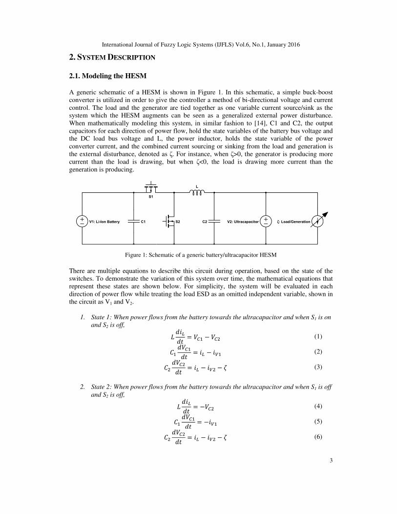
A generic schematic of a HESM is shown in Figure 1. In this schematic, a simple buck
converter is utilized in order to give the controller a method of bi
control. The load and the generator ar
system which the HESM augments can be seen as a generalized external power disturbance.
When mathematically modeling this s
capacitors for each direction of power flow, hold the state variables of the battery bus voltage and
the DC load bus voltage and L, the power inductor, holds the state variable of the power
converter current, and the combined current sourcing or sinking from the load and g
the external disturbance, denoted as
current than the load is drawing, but when
generation is producing.
Figure 1: Schematic of a gen
There are multiple equations to describe this circuit during operation, based on the state of the
switches. To demonstrate the variation of this system over time, the mathematical equations that
represent these states are shown below. For simplicity, the system will be evaluated in each
direction of power flow while treating the load ESD as an omitted independe
the circuit as V1 and V2.
1. State 1: When power flows from the battery towards the ultracapacitor and when S
and S2 is off,
2. State 2: When power flows from the battery towards the ultracapacitor and when S
and S2 is off,
International Journal of Fuzzy Logic Systems (IJFLS) Vol.6, No.1, January 201
A generic schematic of a HESM is shown in Figure 1. In this schematic, a simple buck
converter is utilized in order to give the controller a method of bi-directional voltage and current
control. The load and the generator are tied together as one variable current source/sink as the
system which the HESM augments can be seen as a generalized external power disturbance.
When mathematically modeling this system, in similar fashion to [14], C1 and C2, the output
ch direction of power flow, hold the state variables of the battery bus voltage and
the DC load bus voltage and L, the power inductor, holds the state variable of the power
converter current, and the combined current sourcing or sinking from the load and g
the external disturbance, denoted as ζ. For instance, when ζ>0, the generator is producing more
current than the load is drawing, but when ζ<0, the load is drawing more current than the
: Schematic of a generic battery/ultracapacitor HESM
There are multiple equations to describe this circuit during operation, based on the state of the
To demonstrate the variation of this system over time, the mathematical equations that
represent these states are shown below. For simplicity, the system will be evaluated in each
direction of power flow while treating the load ESD as an omitted independent variable, shown in
State 1: When power flows from the battery towards the ultracapacitor and when S
State 2: When power flows from the battery towards the ultracapacitor and when S
2016
3
A generic schematic of a HESM is shown in Figure 1. In this schematic, a simple buck-boost
directional voltage and current
e tied together as one variable current source/sink as the
system which the HESM augments can be seen as a generalized external power disturbance.
], C1 and C2, the output
ch direction of power flow, hold the state variables of the battery bus voltage and
the DC load bus voltage and L, the power inductor, holds the state variable of the power
converter current, and the combined current sourcing or sinking from the load and generation is
>0, the generator is producing more
<0, the load is drawing more current than the
There are multiple equations to describe this circuit during operation, based on the state of the
To demonstrate the variation of this system over time, the mathematical equations that
represent these states are shown below. For simplicity, the system will be evaluated in each
nt variable, shown in
State 1: When power flows from the battery towards the ultracapacitor and when S1 is on
(1)
(2)
(3)
State 2: When power flows from the battery towards the ultracapacitor and when S1 is off
(4)
(5)
(6)
International Journal of Fuzzy Logic Systems (IJFLS) Vol.
3. State 3: When power flows from the ultracapacitor towards the
and S2 is on,
4. State 4: When power flows from the ultracapacitor towards the battery and when S
and S2 is off,
These mathematical equations are presented here to enforce the idea that this system is time
varying, with four different plant descriptions, depending on the state of 2
there are mathematical methods in which these equations could be combined to produce a time
average model in which the controller could be evaluated, it was decided that a more accurate
model could be created using MATLAB/Simulink’s SimP
evaluation in order to utilize the toolbox’s lithium ion battery model and additional component
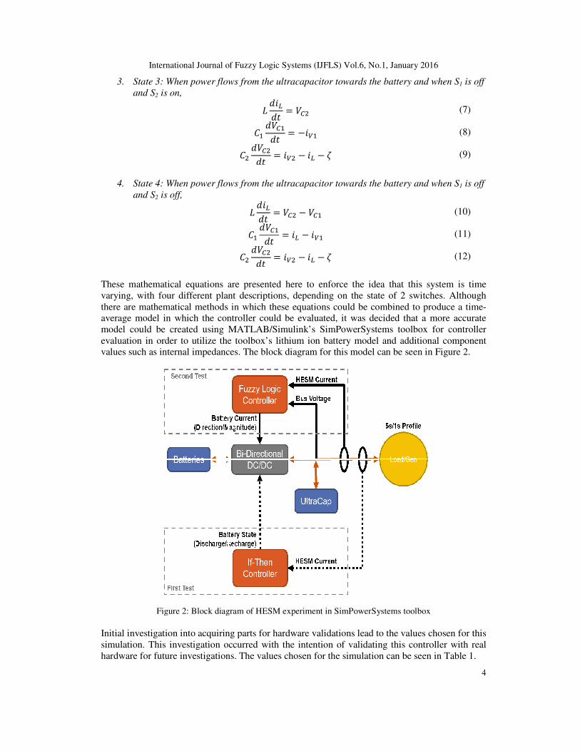
values such as internal impedances. The block diagram for this model can be seen in Figure 2.
Figure 2: Block diagram of
Initial investigation into acquiring parts for hardware validations lead to the values chosen for this
simulation. This investigation occurred with the intention of validating this controller with real
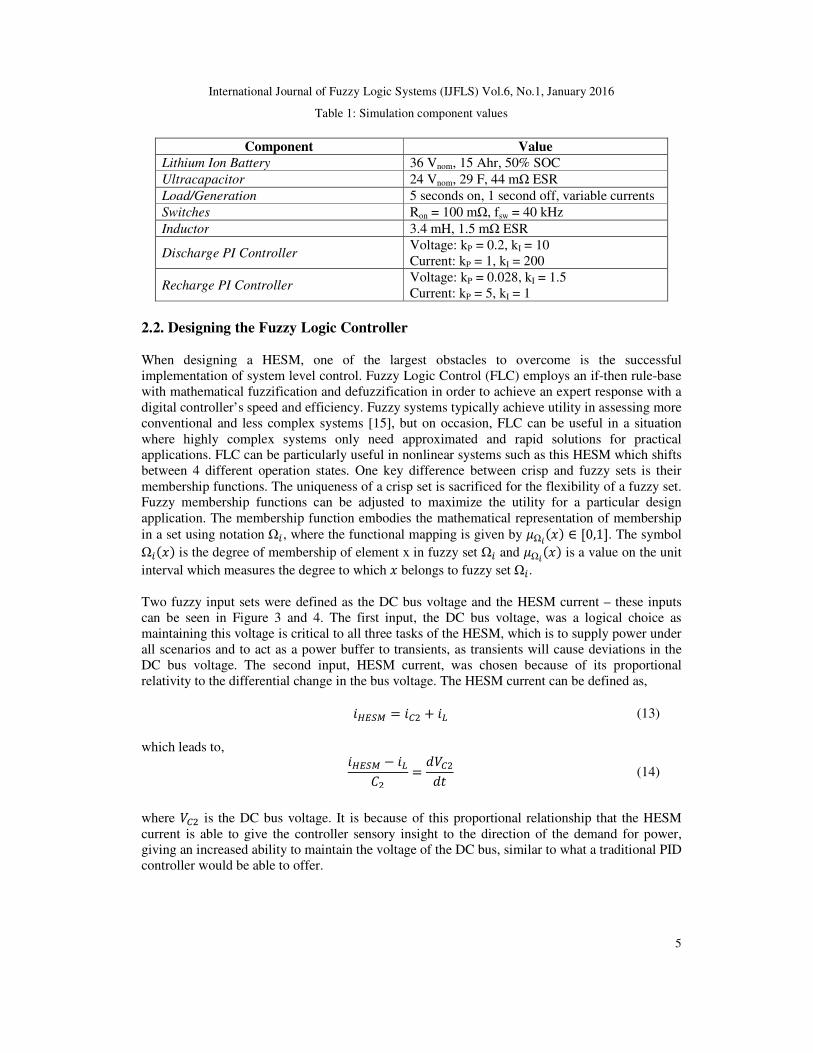
hardware for future investigations. The values chosen for the simulation can be seen in Table 1.
International Journal of Fuzzy Logic Systems (IJFLS) Vol.6, No.1, January 201
State 3: When power flows from the ultracapacitor towards the battery and when S
State 4: When power flows from the ultracapacitor towards the battery and when S
These mathematical equations are presented here to enforce the idea that this system is time
varying, with four different plant descriptions, depending on the state of 2 switches. Although
there are mathematical methods in which these equations could be combined to produce a time
average model in which the controller could be evaluated, it was decided that a more accurate
model could be created using MATLAB/Simulink’s SimPowerSystems toolbox for controller
evaluation in order to utilize the toolbox’s lithium ion battery model and additional component
values such as internal impedances. The block diagram for this model can be seen in Figure 2.
Figure 2: Block diagram of HESM experiment in SimPowerSystems toolbox
Initial investigation into acquiring parts for hardware validations lead to the values chosen for this
simulation. This investigation occurred with the intention of validating this controller with real
or future investigations. The values chosen for the simulation can be seen in Table 1.
2016
4
battery and when S1 is off
(7)
(8)
(9)
State 4: When power flows from the ultracapacitor towards the battery and when S1 is off
(10)
(11)
(12)
These mathematical equations are presented here to enforce the idea that this system is time
switches. Although
there are mathematical methods in which these equations could be combined to produce a time-
average model in which the controller could be evaluated, it was decided that a more accurate
owerSystems toolbox for controller
evaluation in order to utilize the toolbox’s lithium ion battery model and additional component
values such as internal impedances. The block diagram for this model can be seen in Figure 2.
Initial investigation into acquiring parts for hardware validations lead to the values chosen for this
simulation. This investigation occurred with the intention of validating this controller with real
or future investigations. The values chosen for the simulation can be seen in Table 1.
International Journal of Fuzzy Logic Systems (IJFLS) Vol.6, No.1, January 2016
5
Table 1: Simulation component values
Component Value
Lithium Ion Battery 36 Vnom, 15 Ahr, 50% SOC
Ultracapacitor 24 Vnom, 29 F, 44 mΩ ESR
Load/Generation 5 seconds on, 1 second off, variable currents
Switches Ron = 100 mΩ, fsw = 40 kHz
Inductor 3.4 mH, 1.5 mΩ ESR
Discharge PI Controller Voltage: kP = 0.2, kI = 10
Current: kP = 1, kI = 200
Recharge PI Controller Voltage: kP = 0.028, kI = 1.5
Current: kP = 5, kI = 1
2.2. Designing the Fuzzy Logic Controller
When designing a HESM, one of the largest obstacles to overcome is the successful
implementation of system level control. Fuzzy Logic Control (FLC) employs an if-then rule-base
with mathematical fuzzification and defuzzification in order to achieve an expert response with a
digital controller’s speed and efficiency. Fuzzy systems typically achieve utility in assessing more
conventional and less complex systems [15], but on occasion, FLC can be useful in a situation
where highly complex systems only need approximated and rapid solutions for practical
applications. FLC can be particularly useful in nonlinear systems such as this HESM which shifts
between 4 different operation states. One key difference between crisp and fuzzy sets is their
membership functions. The uniqueness of a crisp set is sacrificed for the flexibility of a fuzzy set.
Fuzzy membership functions can be adjusted to maximize the utility for a particular design
application. The membership function embodies the mathematical representation of membership
in a set using notation Ω , where the functional mapping is given by Ω ∈ [0,1]. The symbol
Ω is the degree of membership of element x in fuzzy set Ω and Ω is a value on the unit
interval which measures the degree to which belongs to fuzzy set Ω.
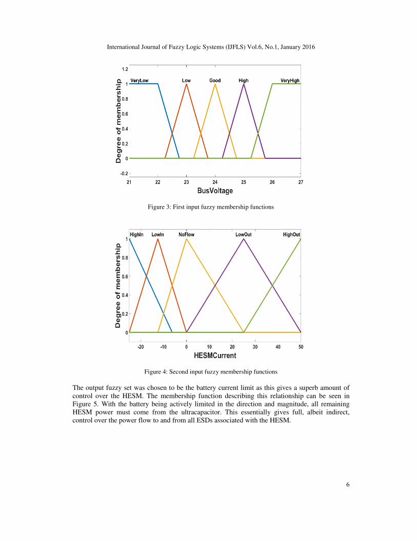
Two fuzzy input sets were defined as the DC bus voltage and the HESM current – these inputs
can be seen in Figure 3 and 4. The first input, the DC bus voltage, was a logical choice as
maintaining this voltage is critical to all three tasks of the HESM, which is to supply power under
all scenarios and to act as a power buffer to transients, as transients will cause deviations in the
DC bus voltage. The second input, HESM current, was chosen because of its proportional
relativity to the differential change in the bus voltage. The HESM current can be defined as,
+ (13)
which leads to,
(14)
where is the DC bus voltage. It is because of this proportional relationship that the HESM
current is able to give the controller sensory insight to the direction of the demand for power,
giving an increased ability to maintain the voltage of the DC bus, similar to what a traditional PID
controller would be able to offer.
International Journal of Fuzzy Logic Systems (IJFLS) Vol.6, No.1, January 2016
6
Figure 3: First input fuzzy membership functions
Figure 4: Second input fuzzy membership functions
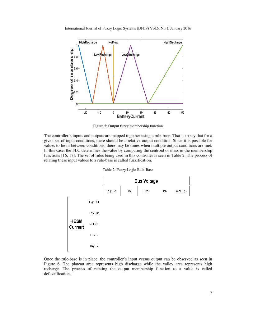
The output fuzzy set was chosen to be the battery current limit as this gives a superb amount of
control over the HESM. The membership function describing this relationship can be seen in
Figure 5. With the battery being actively limited in the direction and magnitude, all remaining
HESM power must come from the ultracapacitor. This essentially gives full, albeit indirect,
control over the power flow to and from all ESDs associated with the HESM.
International Journal of Fuzzy Logic Systems (IJFLS) Vol.
Figure 5
The controller’s inputs and outputs are mapped together using a rule
given set of input conditions, there should be a relative output condition. Since it is possible for
values to lie in-between conditions, there may be times when multipl
In this case, the FLC determines the value by computing the centroid of mass
functions [16, 17]. The set of rules being used in this controller is seen in Table 2. The process of
relating these input values to a rule
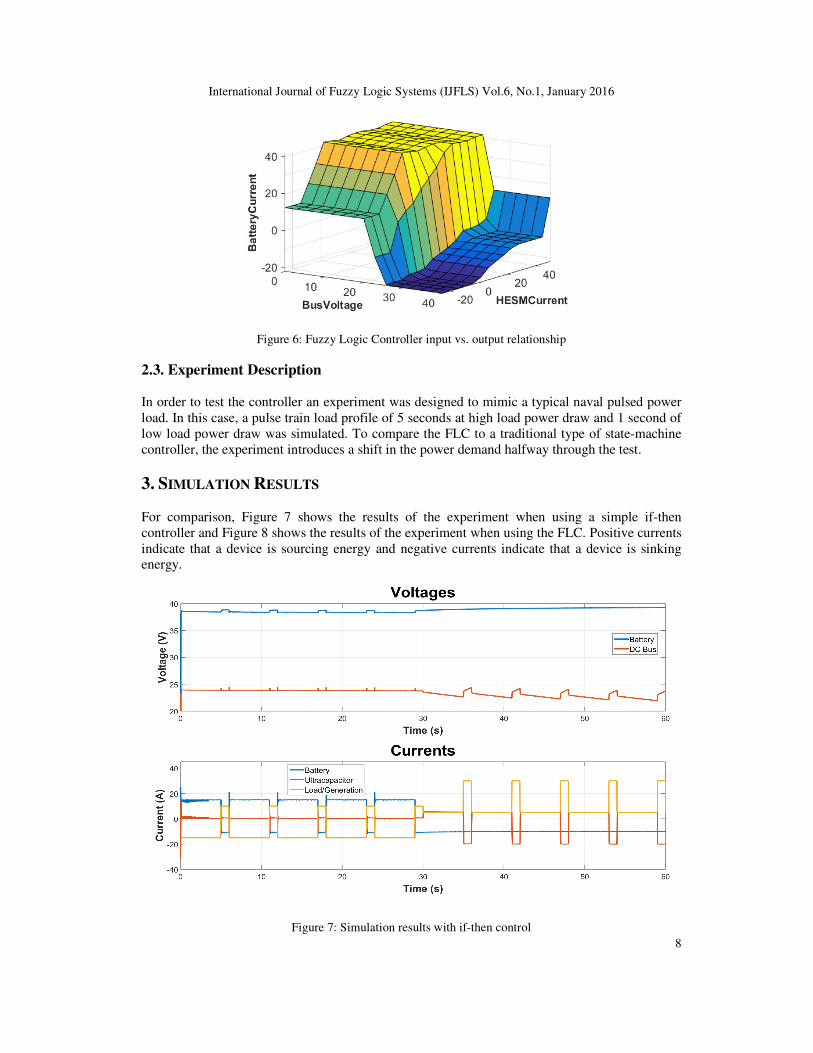
Once the rule-base is in place, the controller’s input versus output can
Figure 6. The plateau area represents high discharge while the valley area represents
recharge. The process of relating the output membership function to a value is called
defuzzification.
International Journal of Fuzzy Logic Systems (IJFLS) Vol.6, No.1, January 201
Figure 5: Output fuzzy membership function
’s inputs and outputs are mapped together using a rule-base. That is to say that for a
given set of input conditions, there should be a relative output condition. Since it is possible for
between conditions, there may be times when multiple output conditions are met.
In this case, the FLC determines the value by computing the centroid of mass in the membership
]. The set of rules being used in this controller is seen in Table 2. The process of
a rule-base is called fuzzification.
Table 2: Fuzzy Logic Rule-Base
base is in place, the controller’s input versus output can be observed as seen in
. The plateau area represents high discharge while the valley area represents
recharge. The process of relating the output membership function to a value is called
2016
7
base. That is to say that for a
given set of input conditions, there should be a relative output condition. Since it is possible for
e output conditions are met.
in the membership
]. The set of rules being used in this controller is seen in Table 2. The process of
be observed as seen in
. The plateau area represents high discharge while the valley area represents high
recharge. The process of relating the output membership function to a value is called
International Journal of Fuzzy Logic Systems (IJFLS) Vol.6, No.1, January 2016
8
Figure 6: Fuzzy Logic Controller input vs. output relationship
2.3. Experiment Description
In order to test the controller an experiment was designed to mimic a typical naval pulsed power
load. In this case, a pulse train load profile of 5 seconds at high load power draw and 1 second of
low load power draw was simulated. To compare the FLC to a traditional type of state-machine
controller, the experiment introduces a shift in the power demand halfway through the test.
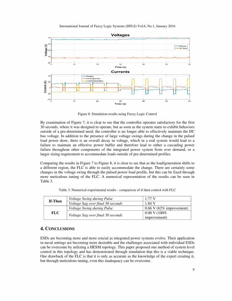
3. SIMULATION RESULTS
For comparison, Figure 7 shows the results of the experiment when using a simple if-then
controller and Figure 8 shows the results of the experiment when using the FLC. Positive currents
indicate that a device is sourcing energy and negative currents indicate that a device is sinking
energy.
Figure 7: Simulation results with if-then control
International Journal of Fuzzy Logic Systems (IJFLS) Vol.6, No.1, January 2016
9
Figure 8: Simulation results using Fuzzy Logic Control
By examination of Figure 7, it is clear to see that the controller operates satisfactory for the first
30 seconds, where it was designed to operate, but as soon as the system starts to exhibit behaviors
outside of a pre-determined need, the controller is no longer able to effectively maintain the DC
bus voltage. In addition to the presence of large voltage swings during the change in the pulsed
load power draw, there is an overall decay in voltage, which in a real system would lead to a
failure to maintain an effective power buffer and therefore lead to either a cascading power
failure throughout other components of the integrated power system from over demand, or a
larger sizing requirement to accommodate loads outside of pre-determined profiles.
Comparing the results in Figure 7 to Figure 8, it is clear to see that as the load/generation shifts to
a different region, the FLC is able to easily accommodate the change. There are certainly some
changes in the voltage swing through the pulsed power load profile, but this can be fixed through
more meticulous tuning of the FLC. A numerical representation of the results can be seen in
Table 3.
Table 3: Numerical experimental results - comparison of if-then control with FLC
If-Then Voltage Swing during Pulse 1.77 V
Voltage Sag over final 30 seconds 1.84 V
FLC
Voltage Swing during Pulse 0.66 V (62% improvement)
Voltage Sag over final 30 seconds 0.00 V (100%
improvement)
4. CONCLUSIONS
ESDs are becoming more and more crucial as integrated power systems evolve. Their application
in naval settings are becoming more desirable and the challenges associated with individual ESDs
can be overcome by utilizing a HESM topology. This paper proposed one method of system level
control in this topology and has demonstrated through simulation that this is a viable technique.
One drawback of the FLC is that it is only as accurate as the knowledge of the expert creating it,
but through meticulous tuning, even this inadequacy can be overcome.
International Journal of Fuzzy Logic Systems (IJFLS) Vol.6, No.1, January 2016
10
ACKNOWLEDGEMENTS
This material is based upon work supported by the US Office of Naval Research (ONR). The
authors would like to express thanks to ONR for their continued support. Any opinions, findings,
and conclusions or recommendations expressed in this publication are those of the authors and do
not necessarily reflect the views of the US Office of Naval Research.
REFERENCES
[1] R. Hebner, "Energy Storage in Future Electric Ships," Electric Ship Research and Development
Consortium, Tallahassee, 2014.
[2] L. Gao and R. A. Dougal, "Power Enhancement of an Actively Controlled Battery/Ultracapacitor
Hybrid," Power Electronics, IEEE Transactions on, vol. 20, no. 1, pp. 236-243, 2005.
[3] I. J. Cohen, J. P. Kelley, D. A. Wetz and J. M. Heinzel, "Evaluation of a Hybrid Energy Storage
Module for Pulsed Power Applications," Plasma Science, IEEE Transactions on, vol. 42, no. 10, pp.
2948-2955, 2014.
[4] S. M. Lukic, S. G. Wirasingha, F. Rodriguez and J. Cao, "Power Management of an
Ultracapacitor/Battery Hybrid Energy Storage System in an HEV," in Vehicle Power and Propulsion
Conference, 2006. VPPC '06. IEEE, Windsor, 2006.
[5] D. Carreira, G. D. Marques and D. M. Sousa, "Hybrid Energy Storage System with a Low Cost
Digital Control," in Compatibility and Power Electronics (CPE), 2015 9th International Conference
on, Costa da Caparica, 2015.
[6] C. Jin, N. Lu, S. Lu, Y. Makarov and R. Dougal, "Coordinated Control Algorithm for Hybrid Energy
Storage Systems," in Power and Energy Society General Meeting, 2011 IEEE, 2011.
[7] Vijay Bhaskar Semwal, Pavan Chakraborty, G.C. Nandi, Less computationally intensive fuzzy logic
(type-1)-based controller for humanoid push recovery, Robotics and Autonomous Systems, vol. 63,
no. 1, pp. 122-135, 2015
[8] Y. Lu, H. L. Hess, D. B. Edwards and , Adaptive Control of an Ultracapacitor Energy Storage System
for Hybrid Electric Vehicles, Antalya: Electric Machines & Drives Conference, 2007. IEMDC '07.
IEEE International, 2007.
[9] C.-H. Wu, P.-Y. Chen and J.-C. . Ke, "On the Study of Energy-Based Control Strategy for a Lithium
Battery/Supercapacitor Hybrid Energy Storage System," in Environmental Science and Information
Application Technology (ESIAT), 2010 International Conference on, Wuhan, 2010.
[10] Z. Yu, Z. Jiang and X. Yu, "Control Strategies for Battery/Supercapacitor Hybrid Energy Storage
Systems," in Energy 2030 Conference, 2008. ENERGY 2008. IEEE, Atlanta, 2008.
[11] D. G. Wilson, R. D. Robinett III and S. Y. Goldsmith, "Renewable Energy Microgrid Control with
Energy Storage Integration," in Power Electronics, Electrical Drivers, Automation and Motion
(SPEEDAM), 2012 International Symposium on, Sorrento, 2012.
[12] I. J. Cohen, D. A. Wetz, C. Storm and J. Heinzel, "Impact of a Hybrid Energy Storage Module on
Power Quality of a Fossil Fuel Generator," in Proceedings of the 2014 American Society of Naval
Engineers Electric Machines Technology Symposium (EMTS), Philadelphia, 2014.
[13] D. A. Wetz, B. Shrestha, S. T. Donahue, D. N. Wong, M. J. Martin and J. M. Heinzel, "Capacity Fade
of 26650 Lithium-Ion Phosphate Batteries Considered for Use Within a Pulsed-Power System's Prime
Power Supply," Plasma Science, IEEE Transactions on, vol. 43, pp. 1448-1455, 2015.
[14] Y. Zhang, J. Zhenhua and Y. Xunwei, "Small-Signal Modeling and Analysis of Battery-
Supercapacitor Hybrid Energy Storage Systems," in Power & Energy Society General Meeting, 2009.
PES '09. IEEE, Calgary, 2009.
[15] T. J. Ross, Fuzzy Logic with Engineering Applications, McGraw-Hill, 1995.
[16] M. Sugeno, "An Introductory Survey of Fuzzy Control," Information Sciences, vol. 36, no. 1, pp. 59-
83, 1985.
[17] C. C. Lee, "Fuzzy Logic in Control Systems: Fuzzy Logic Controller. II.," Systems, Man and
Cybernetics, IEEE Transactions on, vol. 20, no. 2, pp. 419-435, 1990.
International Journal of Fuzzy Logic Systems (IJFLS) Vol.
Authors Isaac J. Cohen was born in Miami, FL in 1988. He received the B.S. degree in
electrical engineering in 2013 from the University of Texas at Arlington, where he is
currently working toward the Ph.D. degree in electrical engineering.He served as Chair
of the Student Branch of IEEE at UTA in 2012, where he received several awards for
his outstanding service. He currently serves as Chair of the Young Professional
affinity group within the IEEE Fort Worth Section.His research interests include
applying control theories to power electronics in microgrid, energy storage, and pulsed
power settings.
David A. Wetz, Jr. was born in El Paso, TX, USA, in 1982. He received the
degrees in electrical engineering and computer
engineering, and the Ph.D. degree in electrical engineering from
University, Lubbock, TX, USA, in 2003,
Post-Doctoral Fellow with the Institute
Texas at Austin, Austin, TX, USA, fro
Associate from 2007 to 2010. He joined the Faculty of Electrical Engineering at
the University of Texas at Arlington, Arlington, TX, USA, as an Assistant Professor
in 2010. His current research interests in
system analysis.
Stepfanie Veiga Received the M.S. degree in Electrical Engineering from Villanova
University, Villanova, PA, USA, in 2013. She spent 4 years in private industry at
firms such as Specialty Minerals Inc., Bethlehem, PA, USA, and Bard, Rao +
Athanas Consulting Engineers, LLC, Philadelphia, PA, USA. She is currently with
the Machinery Technology Research & Development Group, Philadelphia Division,
Naval Surface Warfare Center, U.S. Navy, Philadelphia, PA, USA, where she has
been for 7 years. She also has prior experience in Shipboard Instrumentation and
System Calibration for the Machinery Information, Sensors, and Control Systems
division at Naval Surface Warfare Center, Philad
include power electronics, converter topologies, pulsed power system, high voltage power systems testing
and evaluation, and real-time power hardware in the loop architecture development and testing.
Qing Dong received the Ph.D. degree in electrical engineering from Temple
University, Philadelphia, PA, USA, in 2011. His thesis topic was titled Multi
Based Federated Control of Large
industry at firms such as Lucent Technologies, Murray Hill, NJ, USA, and Parker
Hannifin Corporation, Cleveland, OH, USA. He is currently with the Machinery
Technology Research & Development Group, Philadelphia Division, Naval Surface
Warfare Center, U.S. Navy, Philadelphia,
He has over a dozen peer-reviewed publications in journals and conference
proceedings. His current research interests include optimal control, large
control, agent-based control methods, and optimizat
John M. Heinzel received the bachelor’s degree
Newark, DE, USA, and the Ph.D. degree in chemical engineering from
University, Auburn, AL, USA.
He is currently a Senior Chemical Engineer
Naval Surface Warfare Center, U.S. Navy, Philadelphia, PA, USA. He also
as the lead on multiple Navy/DoD
a Multiphysics approach toward solving problem
into practical applications. His area
energy conversion research and development, in particular, advanced fuel cell and
energy storage systems, and other power gener
International Journal of Fuzzy Logic Systems (IJFLS) Vol.6, No.1, January 201
was born in Miami, FL in 1988. He received the B.S. degree in
electrical engineering in 2013 from the University of Texas at Arlington, where he is
currently working toward the Ph.D. degree in electrical engineering.He served as Chair
ch of IEEE at UTA in 2012, where he received several awards for
his outstanding service. He currently serves as Chair of the Young Professional
affinity group within the IEEE Fort Worth Section.His research interests include
ower electronics in microgrid, energy storage, and pulsed
born in El Paso, TX, USA, in 1982. He received the B.Sc.
ngineering and computer science, the M.Sc. degree in electrical
and the Ph.D. degree in electrical engineering from Texas Tech
University, Lubbock, TX, USA, in 2003, 2004, and 2006, respectively.He was a
Doctoral Fellow with the Institute for Advanced Technology, University of
Austin, Austin, TX, USA, from 2006 to 2007, where he was also a Research
He joined the Faculty of Electrical Engineering at
Arlington, Arlington, TX, USA, as an Assistant Professor
research interests include pulsed power, power electronics, energy storage, and
Received the M.S. degree in Electrical Engineering from Villanova
University, Villanova, PA, USA, in 2013. She spent 4 years in private industry at
ch as Specialty Minerals Inc., Bethlehem, PA, USA, and Bard, Rao +
Athanas Consulting Engineers, LLC, Philadelphia, PA, USA. She is currently with
the Machinery Technology Research & Development Group, Philadelphia Division,
.S. Navy, Philadelphia, PA, USA, where she has
been for 7 years. She also has prior experience in Shipboard Instrumentation and
System Calibration for the Machinery Information, Sensors, and Control Systems
division at Naval Surface Warfare Center, Philadelphia. Her current research interests
include power electronics, converter topologies, pulsed power system, high voltage power systems testing
time power hardware in the loop architecture development and testing.
eceived the Ph.D. degree in electrical engineering from Temple
University, Philadelphia, PA, USA, in 2011. His thesis topic was titled Multi-Agent
Based Federated Control of Large-Scale Systems. He spent 16 years in private
Technologies, Murray Hill, NJ, USA, and Parker
Hannifin Corporation, Cleveland, OH, USA. He is currently with the Machinery
Technology Research & Development Group, Philadelphia Division, Naval Surface
nter, U.S. Navy, Philadelphia, PA, USA, where he has been for 12 years.
reviewed publications in journals and conference
proceedings. His current research interests include optimal control, large-scale system dynamics and
based control methods, and optimization theory.
received the bachelor’s degree from the University of Delaware,
and the Ph.D. degree in chemical engineering from Auburn
University, Auburn, AL, USA.
He is currently a Senior Chemical Engineer with the Carderock Division,
Center, U.S. Navy, Philadelphia, PA, USA. He also serves
as the lead on multiple Navy/DoD programs in these areas, and emphasizes
approach toward solving problems and transitioning new hardware
into practical applications. His area of cognizance is chemical systems related to
development, in particular, advanced fuel cell and
other power generation, directed energy, and thermal management areas.
2016
11
clude pulsed power, power electronics, energy storage, and power
include power electronics, converter topologies, pulsed power system, high voltage power systems testing
time power hardware in the loop architecture development and testing.
scale system dynamics and
ation, directed energy, and thermal management areas.


![Optimal Fuzzy Logic Energy Management Strategy of Hybrid ... · Energy management of a hybrid electric vehicle: an approach based on type-2 fuzzy logic by Dr Solano Martinez [2] Javier](https://img.pdfslide.us/doc/110x75/5fb87a61eff712444b3e5ef7/optimal-fuzzy-logic-energy-management-strategy-of-hybrid-energy-management-of.jpg)