Embed Size (px)
Citation preview

AVL International Commercial Powertrain Conference – organized by AVL in co-operation with SAE International
ICPC 2013 – 3.3
Fuel efficiency in construction equipment – optimize the machine as one system
Gunnar Stein, Anders Fröberg, Jonas Martinsson, Björn Brattberg, Reno Filla, Joakim Unnebäck
VOLVO Construction Equipment
Copyright © 2013 AVL List GmbH and SAE International
ABSTRACT
In order to further optimize the fuel efficiency and productivity of construction equipment, 3 main potentials have been identified:
• job site optimization • machine use optimization • machine optimization
The focus of this paper is the machine optimization on the example of a wheel loader.
Optimizing losses in individual components must be done, but it will not be a game changer for fuel efficiency improvement. Three areas for promising improvement potentials:
• Optimizing the systems interactions • Decoupling of systems • Reduction of losses
One example is shown for a total machine optimization approach: the “Reverse by Braking” function is using the machine operating brakes to slow down the machine during power shuttle instead of using the engine power.
Decoupling of systems requires continuously variable transmission (CVT) functionality for the driveline. This can be achieved with hydraulic or electric CVTs. Two examples for decoupling systems are shown: the Volvo hydrostatic powersplit CVT prototype and a series hybrid wheel loader.
Further future potentials are explored, while the driveline and hydraulic technology are the enablers for drastic improvements: electrified site, plug in hybrid, alternative fuels, and new machine concepts.
INTRODUCTION
As in all industries we need to perform continuous improvements of our products in order to meet increasing demands in varies aspects. Some of them are: environmental care, safety, health of operators, ease of operation, maintainability, serviceability, easy of repair, availability of fuels, productivity and fuel efficiency and hence total cost of ownership (TCO). As our environmental boundary conditions change continuously – such as: perceived value of health and safety, environmental care, fuel availability and price, new development of technologies and components, competitive pressure – new technologies become commercially viable. The key for all technology options however is, to add value for money to our customers and add value to our company.
As the automotive industry is moving towards hybrid technologies, especially electrical hybrids, the traditional vehicle architecture is broken up. This offers opportunities for Construction Equipment manufacturers that develop all major subsystems within their organization or group, as the machine can be optimized as one system. Volvo Construction Equipment is one of these players in the industry, especially with the background of Volvo Truck and Bus within the group. But also conventional machine architectures offer opportunities for total system optimization, if different vehicle systems are linked in a smart way.
This paper will show benefits of 3 driveline technology steps and their integration into the machine on the example of a wheel loader:
• traditional powershift and torque converter transmission
• CVT transmission • Serial hybrid with energy storage
ICPC 2013 – 3.3
2
Furthermore an outlook will be given in which area further improvement potentials can be found.
FUEL EFFICIENCY IMPROVEMENT POTENTIALS IN A WHEEL LOADER
The definition for Fuel Efficiency (FE) as used in this paper is the following:
where the fuel efficiency (measured in tons of material moved per liter fuel consumed), is the productivity of the machine (tons per hour) divided by the Fuel Consumption (FC) (measured in liter fuel consumed per hour).
So an improvement in the Fuel Efficiency can be achieved by increasing the productivity (fuel consumption neutral) or reducing the fuel consumption (productivity neutral). In reality customers expect an improvement of both factors simultaneously.
In marketing material the improvement potentials are typically stated as “up to X%” saving. The real life experience is very cycle dependent and differs from one customer to another. The average improvement depends largely on the application, the size of the machine, the driving cycle, the driver, the combination of the machine with others on the site aso. There are many factors influencing the real values, beyond the machine technology. Never the less, the “up to X%” values are a good indicator to compare technologies, as these values often refer to similar cycles and are typically measured in controlled environments, so relative comparisons are possible. Each equipment manufacturer carries out customer clinic tests, so all know where they stand vs. competition, which allows comparing absolute Fuel Economy values. This paper will use the “up to X%” values to compare different technologies vs. each other in order to understand the technology potentials.
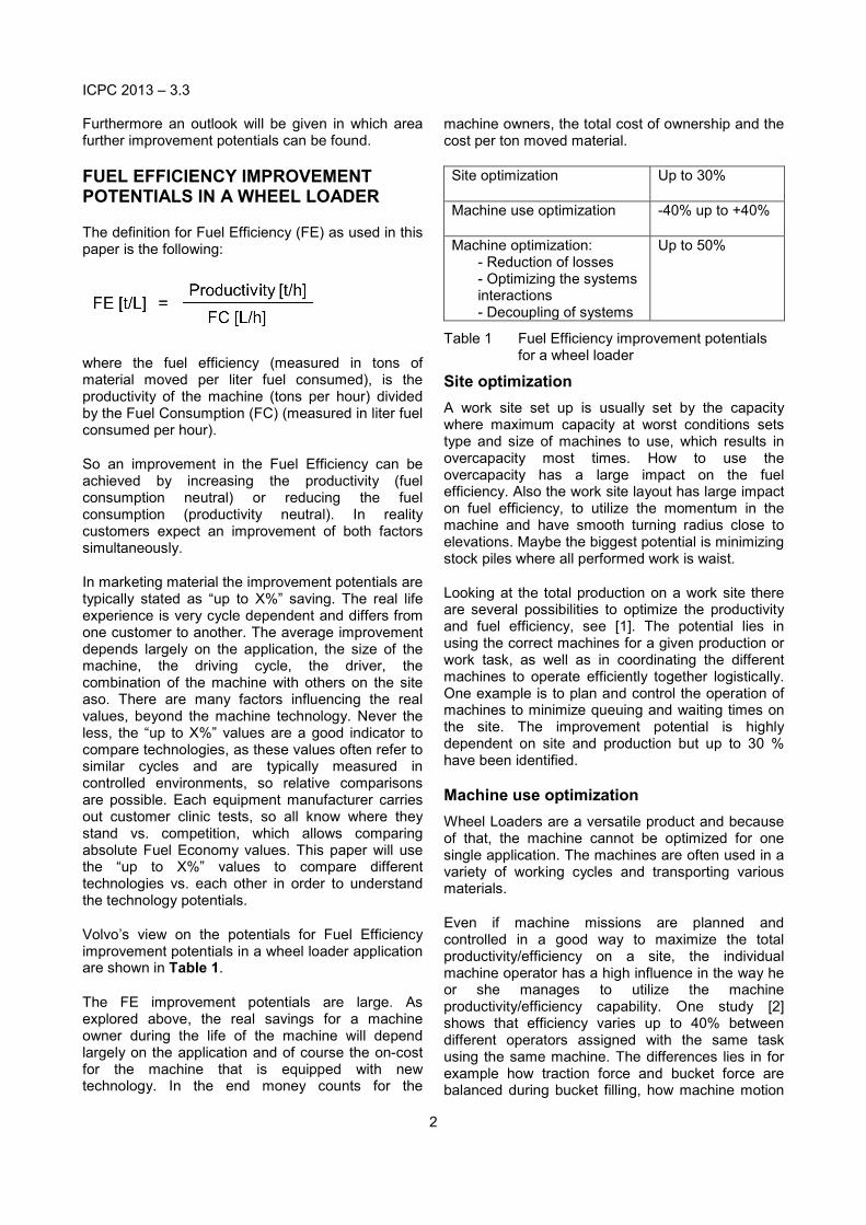
Volvo’s view on the potentials for Fuel Efficiency improvement potentials in a wheel loader application are shown in Table 1.
The FE improvement potentials are large. As explored above, the real savings for a machine owner during the life of the machine will depend largely on the application and of course the on-cost for the machine that is equipped with new technology. In the end money counts for the
machine owners, the total cost of ownership and the cost per ton moved material.
Site optimization Up to 30%
Machine use optimization -40% up to +40%
Machine optimization: - Reduction of losses - Optimizing the systems interactions - Decoupling of systems
Up to 50%
Table 1 Fuel Efficiency improvement potentials for a wheel loader
Site optimization A work site set up is usually set by the capacity where maximum capacity at worst conditions sets type and size of machines to use, which results in overcapacity most times. How to use the overcapacity has a large impact on the fuel efficiency. Also the work site layout has large impact on fuel efficiency, to utilize the momentum in the machine and have smooth turning radius close to elevations. Maybe the biggest potential is minimizing stock piles where all performed work is waist.
Looking at the total production on a work site there are several possibilities to optimize the productivity and fuel efficiency, see [1]. The potential lies in using the correct machines for a given production or work task, as well as in coordinating the different machines to operate efficiently together logistically. One example is to plan and control the operation of machines to minimize queuing and waiting times on the site. The improvement potential is highly dependent on site and production but up to 30 % have been identified.
Machine use optimization Wheel Loaders are a versatile product and because of that, the machine cannot be optimized for one single application. The machines are often used in a variety of working cycles and transporting various materials.
Even if machine missions are planned and controlled in a good way to maximize the total productivity/efficiency on a site, the individual machine operator has a high influence in the way he or she manages to utilize the machine productivity/efficiency capability. One study [2] shows that efficiency varies up to 40% between different operators assigned with the same task using the same machine. The differences lies in for example how traction force and bucket force are balanced during bucket filling, how machine motion

ICPC 2013 – 3.3
3
and bucket motion are coordinated by the operator using levers and pedals, and in the end how these tradeoffs make the machine systems like engine, transmission, and hydraulics, work together. Construction machines efficiency varies even among experienced operators and requires good knowledge of subsystem interaction in order to work efficiently. Hence, there is a high potential for operator assisting systems or even for complete autonomous operation.
Machine optimization The potentials for the machine optimization can be grouped into three categories:
• Reduction of losses • Optimizing the systems interactions • Decoupling of systems
In the following, the optimization potentials in one working cycles will be identified and 3 technical solutions to capture these potentials are shown. In all cases the driveline technology is the enabler to capture the potentials.
REFERENCE WORKING CYCLES
Two working cycles are most relevant when comparing efficiency in a wheel loader application: Load & Carry and Short Loading Cycle Figure 1.
Figure 1 Short Loading Cycle
Description Short Loading Cycle:
1. Bucket filling 2. Leaving bank 3. Retardation for reversing 4. Reversing 5. Towards Load receiver
6. At load receiver 7. Leaving load receiver 8. Retardation for reversing 9. Towards bank 10. Retardation towards bank
Figure 2 Power distribution in a Short Loading Cycle
Figure 2 shows the distribution of power - hydraulics vs. drivetrain - in the short loading cycle. The x-axis shows time and y-axis power in % of max. engine power. The machine used is equipped with 4 speed powershift transmission and torque converter (no lock up). This graph is used as the baseline for all potential evaluations.
Figure 3 Engine torque and speed plot TQ powershift transmission
The phases are separated by white vertical lines with the numbering as in above description. The peak power demand is in the bucket filling phase, where both, hydraulics and drivetrain, are consuming up to the maximum engine power. This phase is also relatively long in the cycle time, so that 40% of the total cycle fuel consumption happens in this phase.

ICPC 2013 – 3.3
4
Figure 3 shows a typical engine torque and speed plot of the short loading cycle on the example of an L 220 G.
MACHINE OPTIMIZATION: ENERGY SAVING POTENTIALS IN WORKING CYCLES
Optimization potentials in the working cycle Three categories of optimization potentials were stated above: Reduction of losses, optimizing the systems interactions, Decoupling of systems.
Losses: There needs to be a continued focus to minimize losses in every component, however the biggest saving potential can be captured by replacing big loss generating components with different technologies. A torque converter generates large losses, up to 25% of engine power in the bucket filling phase and up to 20% of engine power during travel (if w/o lockup). As the bucket filling phase is contributing with 40% of the fuel consumption in a short loading cycle, the reduction of TQ losses in bucket filling is the single biggest saving potential.
For the hydraulic system there is a large potential during phases where no work is performed - tilting to empty bucket, lowering boom. In these conditions the hydraulic pumps are working against the backpressure in the system. Of course there is room for general efficiency improvement also in the hydraulic system.
Optimizing system interactions: The biggest potential in this category is the phlegmatization of the engine power by energy storage. This means that in phases of little power demand the energy storage device is charged and that energy is used to boost in high demand conditions. In the investigated cycle the average power demand is only 60% of the available peak power, however peak power is needed for performance in certain conditions as combined lifting in uphill conditions to feed a crusher.
A very large factor for an efficient use of the machine is the machine harmony, the balance of hydraulics vs. propulsion system and the ease of controlling the two. Achieving a good balance has a large impact on the bucket filling ability, and hence the productivity of the machine in real life.
Decoupling of systems: The individual system elements of the machine (i.e. engine, hydraulics and propulsion) have different best efficiency operating points. The target for a machine configuration is to
match the components regarding their best efficiency points for average working cycles. This is always a compromise. Higher freedom in controlling component operating points individually, will lead to better overall machine efficiency. It is particularly relevant to operate the engine in the sweet spots of the fuel map (lowest BSFC). So fixed ratios or limited flexibility of ratios between hydraulic flow and engine rpm will lead to high engine rpm at relatively low load and hence sub optimal fuel consumption for the power demand. The same principle applies for the propulsion system.
Technical approaches With regards to machine optimization, Volvo CE has investigated different technical solutions in a step wise approach, while some solutions are launched to the market, other solutions have been analyzed with prototypes. Table 2 shows the Fuel Efficiency improvement potentials by means of machine optimization. It also shows the area of improvement in the cycle and the technical approach to capture the potentials.
Up to 15%:
• Retardation: using brakes instead of engine • Reduction of losses: TQ lock-up functionality Up to 25%:
• Reduction of losses: CVT instead of torque converter
• Decoupling of engine speed and wheel speed Up to 50%:
• Reduction of losses: CVT instead of torque converter
• Decoupling of engine speed, wheel speed and hydraulic flow
• Retardation and attachments: energy recovery • Engine phlegmatization: downsizing and
boosting
Table 2 Machine optimization: Fuel Efficiency improvement potentials and technical approach.
In the following the technical solutions for the 3 steps are shown.
VOLVO OPTISHIFT
The Volvo Optishift feature has been introduced for L110 – L 250 G-series models. The technical solution consists of a lock-up torque converter and a functionality that is referred to as “Reverse by Braking (RBB)”. This functionality uses the wheel brakes for the retardation of the machine during the
ICPC 2013 – 3.3
5
powershuttle operation (phases 3 and 8 in the driving cycle). Powershuttle is the automated shifting from reverse to forward and vice versa by a push of a button. Machines without this option use engine power to slow the vehicle down and hence consume fuel for this action.
Fuel efficiency improvements have been demonstrated up to 15% while the RBB has the biggest effect in the short loading cycle, the lock-up functionality in load and carry and transport cycles. Together with the introduction of the Optishift, the gear shift quality was improved.
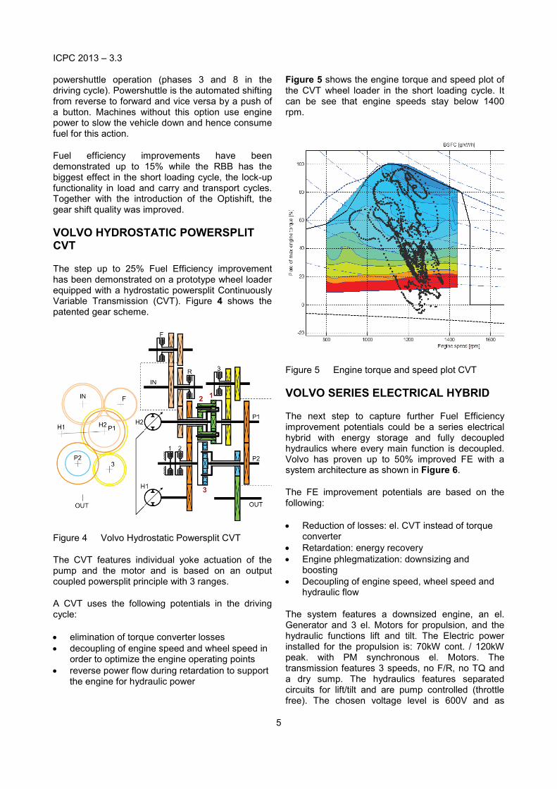
VOLVO HYDROSTATIC POWERSPLIT CVT
The step up to 25% Fuel Efficiency improvement has been demonstrated on a prototype wheel loader equipped with a hydrostatic powersplit Continuously Variable Transmission (CVT). Figure 4 shows the patented gear scheme.
Figure 4 Volvo Hydrostatic Powersplit CVT
The CVT features individual yoke actuation of the pump and the motor and is based on an output coupled powersplit principle with 3 ranges.
A CVT uses the following potentials in the driving cycle:
• elimination of torque converter losses • decoupling of engine speed and wheel speed in
order to optimize the engine operating points • reverse power flow during retardation to support
the engine for hydraulic power
Figure 5 shows the engine torque and speed plot of the CVT wheel loader in the short loading cycle. It can be see that engine speeds stay below 1400 rpm.
Figure 5 Engine torque and speed plot CVT
VOLVO SERIES ELECTRICAL HYBRID
The next step to capture further Fuel Efficiency improvement potentials could be a series electrical hybrid with energy storage and fully decoupled hydraulics where every main function is decoupled. Volvo has proven up to 50% improved FE with a system architecture as shown in Figure 6.
The FE improvement potentials are based on the following:
• Reduction of losses: el. CVT instead of torque converter
• Retardation: energy recovery • Engine phlegmatization: downsizing and
boosting • Decoupling of engine speed, wheel speed and
hydraulic flow
The system features a downsized engine, an el. Generator and 3 el. Motors for propulsion, and the hydraulic functions lift and tilt. The Electric power installed for the propulsion is: 70kW cont. / 120kW peak. with PM synchronous el. Motors. The transmission features 3 speeds, no F/R, no TQ and a dry sump. The hydraulics features separated circuits for lift/tilt and are pump controlled (throttle free). The chosen voltage level is 600V and as

ICPC 2013 – 3.3
6
energy storage device a supercapacitor with 400 Wh capacity.
Figure 6 Components of Volvo Series El. Hybrid
Figure 7 Engine torque and speed plot Volvo Series El. Hybrid
It can be seen in Figure 7 that the control strategy avoides high fuel comsumption operating points in the engine map and at very low rpm if the power is not needed. In the series hybrid the engine becomes a pure genset that delivers power. Also the hydraulic pumps are disconnected from the engine, hence the optimum engine operating point can be freely chosen. Compared to that, the CVT solution featured a fixed hydraulic mounting to the engine.
For the series hybrid setup the engine is controlled to minimize losses for the total power delivering system, i.e. engine, generator, and energy storage
together. This is a balance that for any given power demand compromises between engine/generator losses and energy storage losses, see [3] and [4].
Figure 7 shows engine operating points for a short loading cycle. For such cycles the energy storage can deliver power to cover for peak demands. That is the reason why the engine is never operated at more than about two thirds of its power capability. The used engine has been dimensioned for an infinitely long uphill transport, about 84kW are required for this usage in this machine. Since the uphill slope is infinitely long, the generator power cannot be topped by the energy storage. Therefore both engine and generator are sized for that operating condition.
CONCLUSIONS - ADDING VALUE
Three possible technical routes have been shown to capture potentials for Fuel Efficiency improvements in the wheel loader application. There is substantial potential - up to 50% improvement - if the machine is optimized by introducing new technologies. New technologies however tend to come with a cost tag!
For the machine owner the cost per ton of moved material counts. So productivity and the total cost of ownership (TCO) are the influencing factors. The cost for fuel in the TCO (10 years) is in the range of 20% for wheel loaders in the class > 15t in Europe (with operator). The purchase price is in the range of 20%. There are various customer groups of course with different buying criteria. A rule of thumb can be applied, that customers’ requests an ROI < 2 years, which leads to basic question: how much technology can the customer afford to buy? Different than in the car industry or industries with public exposure (i.e. city busses), the construction equipment industry cannot count on any image driven purchase decisions - money counts.
There is an opportunity however to provide additional features and added value with a new technology, for example increased durability due to reduced number of parts, improved ease of operation, new features aso.
The next challenge is the financial view of the machine OEM: there are of course targets on machine margin, ROI for development projects and amount of invest. Shareholders are asking for added value.
OEMs are different, in terms of manufacturing depth, customer groups and applications, global sales
ICPC 2013 – 3.3
7
footprint, industrial footprint, supplier base and synergies within the group. The current competitive landscape shows that various technical solutions are launched to the market and that the diversity of technical solutions in the market grows. Market launches include CVT and hybrid solutions on a hydraulic and electrical base.
Every OEM needs to define its way to add value to customers and shareholders, there is no “silver bullet”. Those OEMs which develop and produce all major components of a machine, benefit form much larger optimization potential and technical choice though.
OUTLOOK
After discussing options for the short and midterm future, how can the far future look like? There are industry trends that can lead to very different machines and business models of selling construction equipment.
To list a few opportunities:
Electrification of job sites Especially in mines and quarries, the electrification of job sites has come quite far. For mining and underground equipment full electric machines are reality. The cost for electric energy (if energy is supplied from a grid) is significantly lower than diesel when taking into account the low efficiency of combustion engines vs. electric power generation. There is a clear potential for a technology shift.
Battery cost Once battery technology matures and is reduced in cost, there is a potential to reroute value streams from fuel suppliers to OEMs. The cost for the battery will be overcompensated by the fuel savings. If the battery is supplied via the OEM, there is a clear business growth opportunity.
Alternative fuels Natural gas is seen as a potential to take some of the share of diesel fuel. Depending on the cost development, this can have an influence on the speed of change of machine technology.
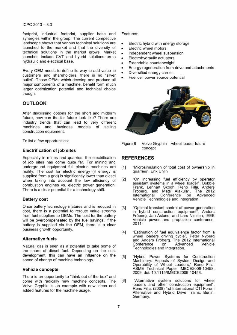
Vehicle concepts There is an opportunity to “think out of the box” and come with radically new machine concepts. The Volvo Gryphin is an example with new ideas and added features for the machine usage.
Features:
• Electric hybrid with energy storage • Electric wheel motors • Independent wheel suspension • Electrohydraulic actuators • Extendable counterweight • Energy regeneration from drive and attachments • Diversified energy carrier • Fuel cell power source potential
Figure 8 Volvo Gryphin – wheel loader future concept
REFERENCES
[1] “Microsimulation of total cost of ownership in quarries”. Erik Uhlin
[2] “On increasing fuel efficiency by operator assistant systems in a wheel loader”. Bobbie Frank, Lennart Skogh, Reno Filla, Anders Fröberg, and Mats Alaküla1. The 2012 International Conference on Advanced Vehicle Technologies and Integration.
[3] “Optimal transient control of power generation
in hybrid construction equipment”, Anders Fröberg, Jan Åslund, and Lars Nielsen, IEEE Vehicle power and propulsion conference, 2011.
[4] “Estimation of fuel equivalence factor from a
wheel loaders driving cycle”. Peter Nyberg and Anders Fröberg. The 2012 International Conference on Advanced Vehicle Technologies and Integration.
[5] “Hybrid Power Systems for Construction
Machinery: Aspects of System Design and Operability of Wheel Loaders,” Reno Filla. ASME Technical Paper IMECE2009-10458, 2009, doi: 10.1115/IMECE2009-10458.
[6] “Alternative system solutions for wheel loaders and other construction equipment”. Reno Filla. (2008) 1st International CTI Forum Alternative and Hybrid Drive Trains, Berlin, Germany.

ICPC 2013 – 3.3
8
http://urn.kb.se/resolve?urn=urn:nbn:se:liu:diva-43948
[7] “Quantifying Operability of Working
Machines,” Reno Filla. Ph.D. thesis, Department of Management and Engineering, Linköping University, Linköping, 2011. http://urn.kb.se/resolve?urn=urn:nbn:se:liu:diva-70394
DEFINITIONS, ACRONYMS, ABBREVIATIONS
FC Fuel consumption FE Fuel Efficiency TQ Torque converter CVT Continuously Variable Transmission RBB Reverse by Braking TCO Total Cost of Ownership BSFC Brake Specific Fuel Consumption OEM Original Equipment Manufacturer