Embed Size (px)
Citation preview
and
Information Kit
Updated: November 2009
2
Node 3/Cupola Overview 3 Node 3 and Cupola: An Introduction Remaining steps before launch Mission Overview
Node 3 7 The Cupola ISS Observation Module 10 Node 3 Internal Racks and Equipment: Environmental Control 12 Water Recovery System Racks Oxygen Generation System Rack Air Revitalization System Waste and Hygiene Compartment Node 3 Internal Racks and Equipment: Conditioning/Exercise Equipment 14 T2 COLBERT Treadmill Advanced Resistive Exercise Device
Node 3 and Cupola On-Orbit Activation 15 Launch and Docking Node 3/Cupola Installation Entering Node 3 Cupola Relocation and Node 3 Activation Cupola Outfitting and Rack Transfer Cupola Thermal Shroud/Launch Bolt Removal Undocking/Landing
ISS Intergovernmental Agreement 18
ISS and Europe’s Major Contributions 19 Columbus Laboratory Node 2 and Node 3 Automated Transfer Vehicle (ATV) European Robotic Arm (ERA) Data Management System (DMS-R) Cupola Observation Module
Credits 22
Contacts 22
3
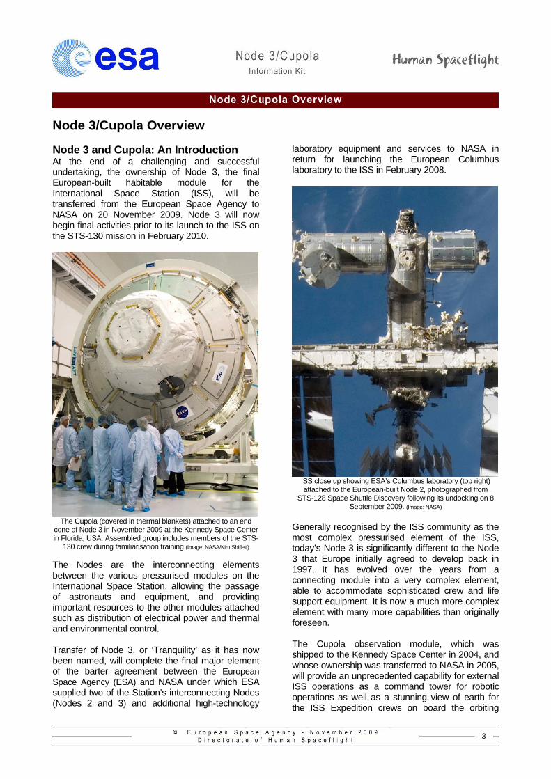
Node 3/Cupola Overview Node 3 and Cupola: An Introduction At the end of a challenging and successful undertaking, the ownership of Node 3, the final European-built habitable module for the International Space Station (ISS), will be transferred from the European Space Agency to NASA on 20 November 2009. Node 3 will now begin final activities prior to its launch to the ISS on the STS-130 mission in February 2010.
The Cupola (covered in thermal blankets) attached to an end
cone of Node 3 in November 2009 at the Kennedy Space Center in Florida, USA. Assembled group includes members of the STS-
130 crew during familiarisation training (Image: NASA/Kim Shiflett)
The Nodes are the interconnecting elements between the various pressurised modules on the International Space Station, allowing the passage of astronauts and equipment, and providing important resources to the other modules attached such as distribution of electrical power and thermal and environmental control. Transfer of Node 3, or ‘Tranquility’ as it has now been named, will complete the final major element of the barter agreement between the European Space Agency (ESA) and NASA under which ESA supplied two of the Station’s interconnecting Nodes (Nodes 2 and 3) and additional high-technology
laboratory equipment and services to NASA in return for launching the European Columbus laboratory to the ISS in February 2008.
ISS close up showing ESA’s Columbus laboratory (top right) attached to the European-built Node 2, photographed from
STS-128 Space Shuttle Discovery following its undocking on 8 September 2009. (Image: NASA)
Generally recognised by the ISS community as the most complex pressurised element of the ISS, today’s Node 3 is significantly different to the Node 3 that Europe initially agreed to develop back in 1997. It has evolved over the years from a connecting module into a very complex element, able to accommodate sophisticated crew and life support equipment. It is now a much more complex element with many more capabilities than originally foreseen. The Cupola observation module, which was shipped to the Kennedy Space Center in 2004, and whose ownership was transferred to NASA in 2005, will provide an unprecedented capability for external ISS operations as a command tower for robotic operations as well as a stunning view of earth for the ISS Expedition crews on board the orbiting
4
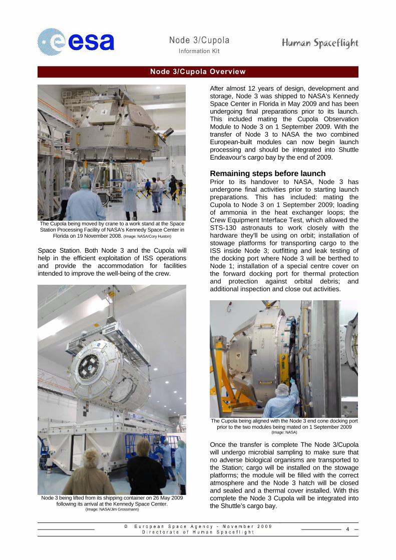
The Cupola being moved by crane to a work stand at the Space Station Processing Facility of NASA's Kennedy Space Center in
Florida on 19 November 2008. (Image: NASA/Cory Huston)
Space Station. Both Node 3 and the Cupola will help in the efficient exploitation of ISS operations and provide the accommodation for facilities intended to improve the well-being of the crew.
Node 3 being lifted from its shipping container on 26 May 2009
following its arrival at the Kennedy Space Center. (Image: NASA/Jim Grossmann)
After almost 12 years of design, development and storage, Node 3 was shipped to NASA’s Kennedy Space Center in Florida in May 2009 and has been undergoing final preparations prior to its launch. This included mating the Cupola Observation Module to Node 3 on 1 September 2009. With the transfer of Node 3 to NASA the two combined European-built modules can now begin launch processing and should be integrated into Shuttle Endeavour’s cargo bay by the end of 2009. Remaining steps before launch Prior to its handover to NASA, Node 3 has undergone final activities prior to starting launch preparations. This has included: mating the Cupola to Node 3 on 1 September 2009; loading of ammonia in the heat exchanger loops; the Crew Equipment Interface Test, which allowed the STS-130 astronauts to work closely with the hardware they'll be using on orbit; installation of stowage platforms for transporting cargo to the ISS inside Node 3; outfitting and leak testing of the docking port where Node 3 will be berthed to Node 1; installation of a special centre cover on the forward docking port for thermal protection and protection against orbital debris; and additional inspection and close out activities.
The Cupola being aligned with the Node 3 end cone docking port
prior to the two modules being mated on 1 September 2009 (Image: NASA)
Once the transfer is complete The Node 3/Cupola will undergo microbial sampling to make sure that no adverse biological organisms are transported to the Station; cargo will be installed on the stowage platforms; the module will be filled with the correct atmosphere and the Node 3 hatch will be closed and sealed and a thermal cover installed. With this complete the Node 3 Cupola will be integrated into the Shuttle’s cargo bay.
5
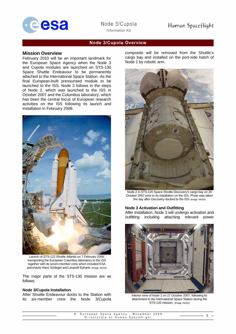
Mission Overview February 2010 will be an important landmark for the European Space Agency when the Node 3 and Cupola modules are launched on STS-130 Space Shuttle Endeavour to be permanently attached to the International Space Station. As the final European-built pressurised module to be launched to the ISS, Node 3 follows in the steps of Node 2, which was launched to the ISS in October 2007 and the Columbus laboratory, which has been the central focus of European research activities on the ISS following its launch and installation in February 2008.
Launch of STS-122 Shuttle Atlantis on 7 February 2008,
transporting the European Columbus laboratory to the ISS together with its seven-member crew which included ESA
astronauts Hans Schlegel and Léopold Eyharts (Image: NASA)
The major parts of the STS-130 mission are as follows: Node 3/Cupola Installation After Shuttle Endeavour docks to the Station with its six-member crew the Node 3/Cupola
composite will be removed from the Shuttle’s cargo bay and installed on the port-side hatch of Node 1 by robotic arm.
Node 2 in STS-120 Space Shuttle Discovery's cargo bay on 26
October 2007 prior to its installation on the ISS. Photo was taken the day after Discovery docked to the ISS (Image: NASA)
Node 3 Activation and Outfitting After installation, Node 3 will undergo activation and outfitting including attaching relevant power
Interior view of Node 2 on 27 October 2007, following its attachment to the International Space Station during the
STS-120 mission. (Image: NASA)
6
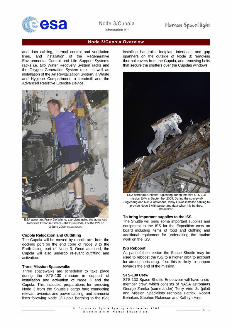
and data cabling, thermal control and ventilation lines, and installation of the Regenerative Environmental Control and Life Support Systems racks i.e. two Water Recovery System racks and the Oxygen Generation System rack, as well as installation of the Air Revitalization System, a Waste and Hygiene Compartment, a treadmill and the Advanced Resistive Exercise Device.
ESA astronaut Frank De Winne, exercises using the advanced
Resistive Exercise Device (aRED) in Node 1 of the ISS on 3 June 2009. (Image: NASA)
Cupola Relocation and Outfitting The Cupola will be moved by robotic arm from the docking port on the end cone of Node 3 to the Earth-facing port of Node 3. Once attached, the Cupola will also undergo relevant outfitting and activation. Three Mission Spacewalks Three spacewalks are scheduled to take place during the STS-130 mission in support of installation and activation of Node 3 and the Cupola. This includes: preparations for removing Node 3 from the Shuttle’s cargo bay; connecting relevant avionics and power cabling, and ammonia lines following Node 3/Cupola berthing to the ISS;
installing handrails, footplate interfaces and gap spanners on the outside of Node 3; removing thermal covers from the Cupola; and removing bolts that secure the shutters over the Cupolas windows.
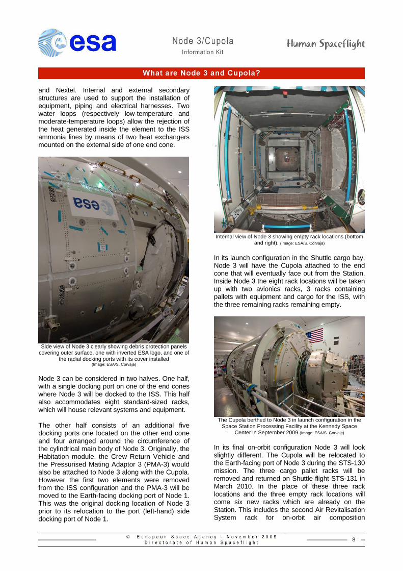
ESA astronaut Christer Fuglesang during the third STS-128
mission EVA in September 2009. During the spacewalk Fuglesang and NASA astronaut Danny Olivas installed cabling to
provide Node 3 with power and data when it is berthed. (Image: NASA)
To bring important supplies to the ISS The Shuttle will bring some important supplies and equipment to the ISS for the Expedition crew on board including items of food and clothing and additional equipment for undertaking the routine work on the ISS. ISS Reboost As part of the mission the Space Shuttle may be used to reboost the ISS to a higher orbit to account for atmospheric drag. If so this is likely to happen towards the end of the mission. STS-130 Crew STS-130 Space Shuttle Endeavour will have a six-member crew, which consists of NASA astronauts George Zamka (commander) Terry Virts Jr. (pilot) and Mission Specialists Nicholas Patrick, Robert Behnken, Stephen Robinson and Kathryn Hire.
7
Node 3
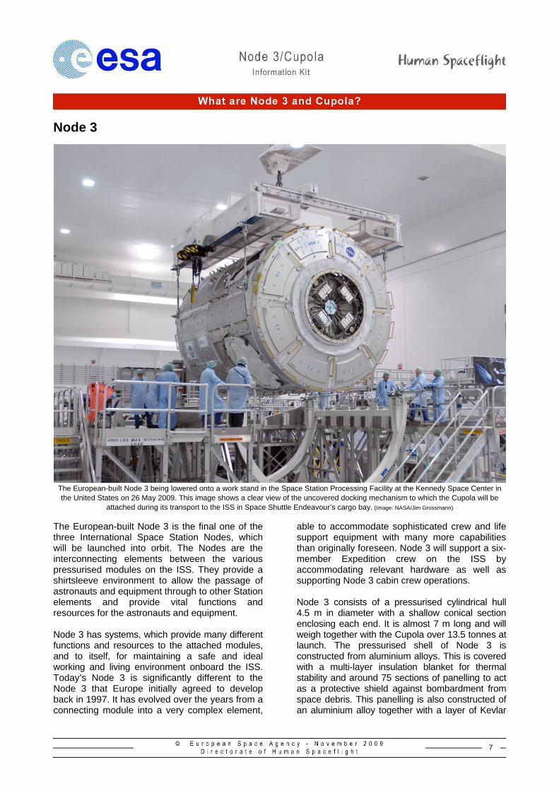
The European-built Node 3 being lowered onto a work stand in the Space Station Processing Facility at the Kennedy Space Center in the United States on 26 May 2009. This image shows a clear view of the uncovered docking mechanism to which the Cupola will be
attached during its transport to the ISS in Space Shuttle Endeavour’s cargo bay. (Image: NASA/Jim Grossmann)
The European-built Node 3 is the final one of the three International Space Station Nodes, which will be launched into orbit. The Nodes are the interconnecting elements between the various pressurised modules on the ISS. They provide a shirtsleeve environment to allow the passage of astronauts and equipment through to other Station elements and provide vital functions and resources for the astronauts and equipment. Node 3 has systems, which provide many different functions and resources to the attached modules, and to itself, for maintaining a safe and ideal working and living environment onboard the ISS. Today’s Node 3 is significantly different to the Node 3 that Europe initially agreed to develop back in 1997. It has evolved over the years from a connecting module into a very complex element,
able to accommodate sophisticated crew and life support equipment with many more capabilities than originally foreseen. Node 3 will support a six-member Expedition crew on the ISS by accommodating relevant hardware as well as supporting Node 3 cabin crew operations. Node 3 consists of a pressurised cylindrical hull 4.5 m in diameter with a shallow conical section enclosing each end. It is almost 7 m long and will weigh together with the Cupola over 13.5 tonnes at launch. The pressurised shell of Node 3 is constructed from aluminium alloys. This is covered with a multi-layer insulation blanket for thermal stability and around 75 sections of panelling to act as a protective shield against bombardment from space debris. This panelling is also constructed of an aluminium alloy together with a layer of Kevlar
8
and Nextel. Internal and external secondary structures are used to support the installation of equipment, piping and electrical harnesses. Two water loops (respectively low-temperature and moderate-temperature loops) allow the rejection of the heat generated inside the element to the ISS ammonia lines by means of two heat exchangers mounted on the external side of one end cone.
Side view of Node 3 clearly showing debris protection panels
covering outer surface, one with inverted ESA logo, and one of the radial docking ports with its cover installed
(Image: ESA/S. Corvaja)
Node 3 can be considered in two halves. One half, with a single docking port on one of the end cones where Node 3 will be docked to the ISS. This half also accommodates eight standard-sized racks, which will house relevant systems and equipment. The other half consists of an additional five docking ports one located on the other end cone and four arranged around the circumference of the cylindrical main body of Node 3. Originally, the Habitation module, the Crew Return Vehicle and the Pressurised Mating Adaptor 3 (PMA-3) would also be attached to Node 3 along with the Cupola. However the first two elements were removed from the ISS configuration and the PMA-3 will be moved to the Earth-facing docking port of Node 1. This was the original docking location of Node 3 prior to its relocation to the port (left-hand) side docking port of Node 1.
Internal view of Node 3 showing empty rack locations (bottom
and right). (Image: ESA/S. Corvaja)
In its launch configuration in the Shuttle cargo bay, Node 3 will have the Cupola attached to the end cone that will eventually face out from the Station. Inside Node 3 the eight rack locations will be taken up with two avionics racks, 3 racks containing pallets with equipment and cargo for the ISS, with the three remaining racks remaining empty.
The Cupola berthed to Node 3 in launch configuration in the
Space Station Processing Facility at the Kennedy Space Center in September 2009 (Image: ESA/S. Corvaje)
In its final on-orbit configuration Node 3 will look slightly different. The Cupola will be relocated to the Earth-facing port of Node 3 during the STS-130 mission. The three cargo pallet racks will be removed and returned on Shuttle flight STS-131 in March 2010. In the place of these three rack locations and the three empty rack locations will come six new racks which are already on the Station. This includes the second Air Revitalisation System rack for on-orbit air composition
9
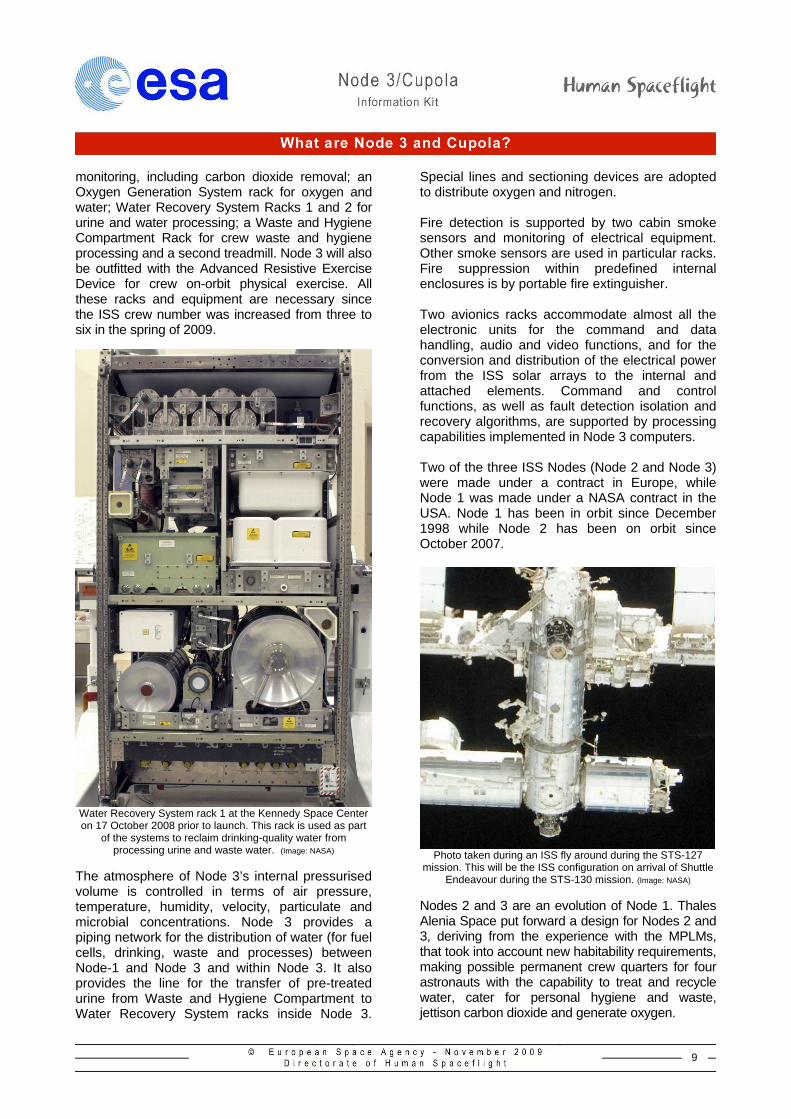
monitoring, including carbon dioxide removal; an Oxygen Generation System rack for oxygen and water; Water Recovery System Racks 1 and 2 for urine and water processing; a Waste and Hygiene Compartment Rack for crew waste and hygiene processing and a second treadmill. Node 3 will also be outfitted with the Advanced Resistive Exercise Device for crew on-orbit physical exercise. All these racks and equipment are necessary since the ISS crew number was increased from three to six in the spring of 2009.
Water Recovery System rack 1 at the Kennedy Space Center on 17 October 2008 prior to launch. This rack is used as part
of the systems to reclaim drinking-quality water from processing urine and waste water. (Image: NASA)
The atmosphere of Node 3’s internal pressurised volume is controlled in terms of air pressure, temperature, humidity, velocity, particulate and microbial concentrations. Node 3 provides a piping network for the distribution of water (for fuel cells, drinking, waste and processes) between Node-1 and Node 3 and within Node 3. It also provides the line for the transfer of pre-treated urine from Waste and Hygiene Compartment to Water Recovery System racks inside Node 3.
Special lines and sectioning devices are adopted to distribute oxygen and nitrogen. Fire detection is supported by two cabin smoke sensors and monitoring of electrical equipment. Other smoke sensors are used in particular racks. Fire suppression within predefined internal enclosures is by portable fire extinguisher. Two avionics racks accommodate almost all the electronic units for the command and data handling, audio and video functions, and for the conversion and distribution of the electrical power from the ISS solar arrays to the internal and attached elements. Command and control functions, as well as fault detection isolation and recovery algorithms, are supported by processing capabilities implemented in Node 3 computers.
Two of the three ISS Nodes (Node 2 and Node 3) were made under a contract in Europe, while Node 1 was made under a NASA contract in the USA. Node 1 has been in orbit since December 1998 while Node 2 has been on orbit since October 2007.
Photo taken during an ISS fly around during the STS-127
mission. This will be the ISS configuration on arrival of Shuttle Endeavour during the STS-130 mission. (Image: NASA)
Nodes 2 and 3 are an evolution of Node 1. Thales Alenia Space put forward a design for Nodes 2 and 3, deriving from the experience with the MPLMs, that took into account new habitability requirements, making possible permanent crew quarters for four astronauts with the capability to treat and recycle water, cater for personal hygiene and waste, jettison carbon dioxide and generate oxygen.
10
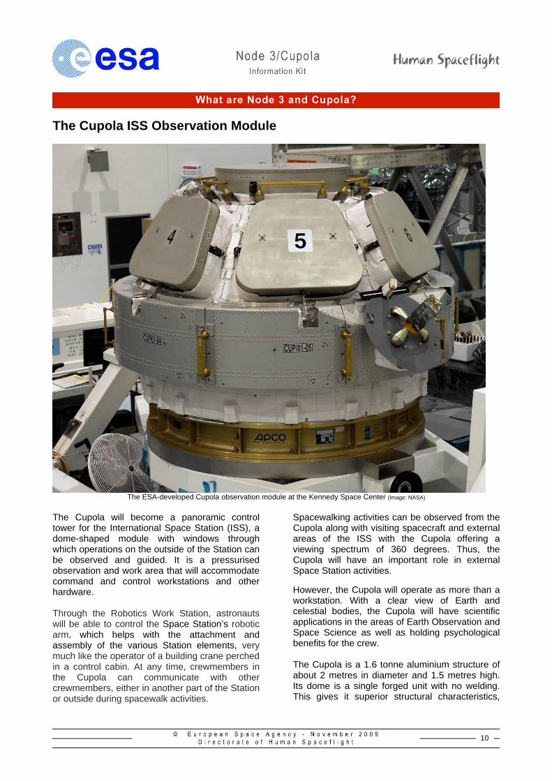
The Cupola ISS Observation Module
The ESA-developed Cupola observation module at the Kennedy Space Center (Image: NASA)
The Cupola will become a panoramic control tower for the International Space Station (ISS), a dome-shaped module with windows through which operations on the outside of the Station can be observed and guided. It is a pressurised observation and work area that will accommodate command and control workstations and other hardware. Through the Robotics Work Station, astronauts will be able to control the Space Station’s robotic arm, which helps with the attachment and assembly of the various Station elements, very much like the operator of a building crane perched in a control cabin. At any time, crewmembers in the Cupola can communicate with other crewmembers, either in another part of the Station or outside during spacewalk activities.
Spacewalking activities can be observed from the Cupola along with visiting spacecraft and external areas of the ISS with the Cupola offering a viewing spectrum of 360 degrees. Thus, the Cupola will have an important role in external Space Station activities.
However, the Cupola will operate as more than a workstation. With a clear view of Earth and celestial bodies, the Cupola will have scientific applications in the areas of Earth Observation and Space Science as well as holding psychological benefits for the crew. The Cupola is a 1.6 tonne aluminium structure of about 2 metres in diameter and 1.5 metres high. Its dome is a single forged unit with no welding. This gives it superior structural characteristics,
11
which helped shorten the production schedule and lower overall costs. The Cupola is a ‘shirt sleeve’ module with six trapezoidal side windows and a circular top window of 80 cm in diameter, making it the largest window ever flown in space. Each window is built using very advanced technologies to defend the sensitive fused silica glass panes from years of exposure to solar radiation and debris impacts.
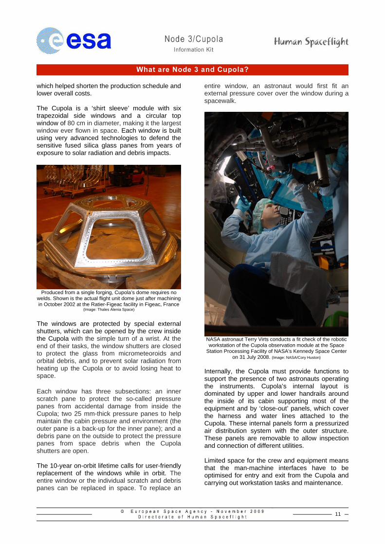
Produced from a single forging, Cupola’s dome requires no
welds. Shown is the actual flight unit dome just after machining in October 2002 at the Ratier-Figeac facility in Figeac, France
(Image: Thales Alenia Space) The windows are protected by special external shutters, which can be opened by the crew inside the Cupola with the simple turn of a wrist. At the end of their tasks, the window shutters are closed to protect the glass from micrometeoroids and orbital debris, and to prevent solar radiation from heating up the Cupola or to avoid losing heat to space. Each window has three subsections: an inner scratch pane to protect the so-called pressure panes from accidental damage from inside the Cupola; two 25 mm-thick pressure panes to help maintain the cabin pressure and environment (the outer pane is a back-up for the inner pane); and a debris pane on the outside to protect the pressure panes from space debris when the Cupola shutters are open. The 10-year on-orbit lifetime calls for user-friendly replacement of the windows while in orbit. The entire window or the individual scratch and debris panes can be replaced in space. To replace an
entire window, an astronaut would first fit an external pressure cover over the window during a spacewalk.
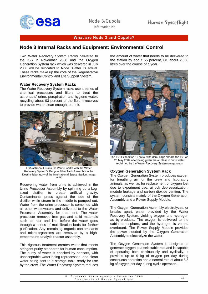
NASA astronaut Terry Virts conducts a fit check of the robotic workstation of the Cupola observation module at the Space
Station Processing Facility of NASA's Kennedy Space Center on 31 July 2008. (Image: NASA/Cory Huston)
Internally, the Cupola must provide functions to support the presence of two astronauts operating the instruments. Cupola’s internal layout is dominated by upper and lower handrails around the inside of its cabin supporting most of the equipment and by ‘close-out’ panels, which cover the harness and water lines attached to the Cupola. These internal panels form a pressurized air distribution system with the outer structure. These panels are removable to allow inspection and connection of different utilities. Limited space for the crew and equipment means that the man-machine interfaces have to be optimised for entry and exit from the Cupola and carrying out workstation tasks and maintenance.
12
Node 3 Internal Racks and Equipment: Environmental Control Two Water Recovery System Racks delivered to the ISS in November 2008 and the Oxygen Generation System rack which was delivered in July 2006 will be relocated to Node 3 after its arrival. These racks make up the core of the Regenerative Environmental Control and Life Support System. Water Recovery System Racks The Water Recovery System racks use a series of chemical processes and filters to treat the astronauts’ urine, perspiration and hygiene water, recycling about 93 percent of the fluid it receives to provide water clean enough to drink.
ESA astronaut Frank De Winne works with the Water
Recovery System’s Recycle Filter Tank Assembly in the Destiny laboratory of the International Space Station. (Image:
NASA) Recovering water from urine is achieved in the Urine Processor Assembly by spinning up a keg-sized distiller to create artificial gravity. Contaminants press against the side of the distiller while steam in the middle is pumped out. Water from the urine processor is combined with all other wastewaters and delivered to the Water Processor Assembly for treatment. The water processor removes free gas and solid materials such as hair and lint, before the water goes through a series of multifiltration beds for further purification. Any remaining organic contaminants and micro-organisms are removed by a high-temperature catalytic reactor assembly. This rigorous treatment creates water that meets stringent purity standards for human consumption. The purity of water is checked by sensors, with unacceptable water being reprocessed, and clean water being sent to a storage tank, ready for use by the crew. The Water Recovery System reduces
the amount of water that needs to be delivered to the station by about 65 percent, i.e. about 2,850 litres over the course of a year.
The ISS Expedition 19 crew with drink bags aboard the ISS on
20 May 2009 after being given the all clear to drink water reclaimed by the Water Recovery System (Image: NASA)
Oxygen Generation System Rack The Oxygen Generation System produces oxygen for breathing air for the crew and laboratory animals, as well as for replacement of oxygen lost due to experiment use, airlock depressurization, module leakage and carbon dioxide venting. The system consists mainly of the Oxygen Generation Assembly and a Power Supply Module. The Oxygen Generation Assembly electrolyzes, or breaks apart, water provided by the Water Recovery System, yielding oxygen and hydrogen as by-products. The oxygen is delivered to the cabin atmosphere, and the hydrogen is vented overboard. The Power Supply Module provides the power needed by the Oxygen Generation Assembly to electrolyze the water. The Oxygen Generation System is designed to generate oxygen at a selectable rate and is capable of operating both continuously and cyclically. It provides up to 9 kg of oxygen per day during continuous operation and a normal rate of about 5.5 kg of oxygen per day during cyclic operation.
13
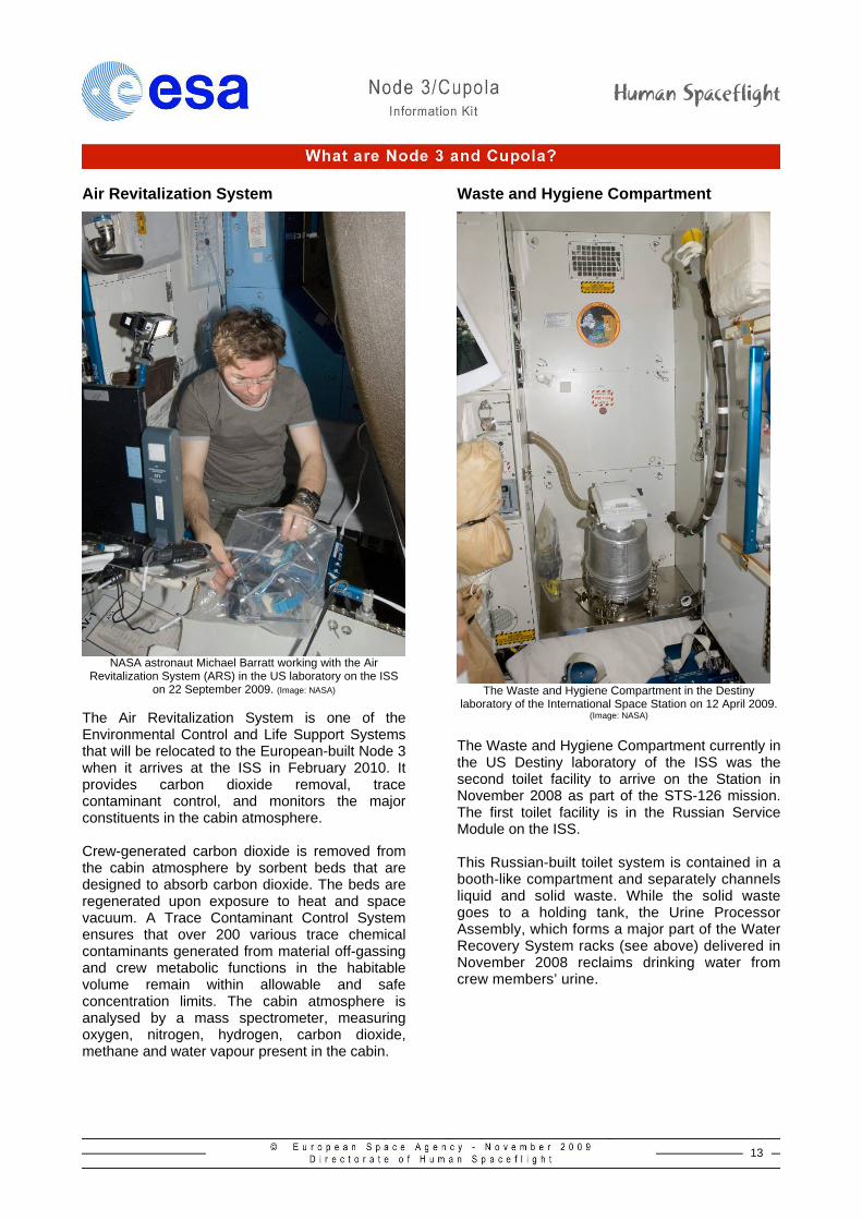
Air Revitalization System
NASA astronaut Michael Barratt working with the Air
Revitalization System (ARS) in the US laboratory on the ISS on 22 September 2009. (Image: NASA)
The Air Revitalization System is one of the Environmental Control and Life Support Systems that will be relocated to the European-built Node 3 when it arrives at the ISS in February 2010. It provides carbon dioxide removal, trace contaminant control, and monitors the major constituents in the cabin atmosphere. Crew-generated carbon dioxide is removed from the cabin atmosphere by sorbent beds that are designed to absorb carbon dioxide. The beds are regenerated upon exposure to heat and space vacuum. A Trace Contaminant Control System ensures that over 200 various trace chemical contaminants generated from material off-gassing and crew metabolic functions in the habitable volume remain within allowable and safe concentration limits. The cabin atmosphere is analysed by a mass spectrometer, measuring oxygen, nitrogen, hydrogen, carbon dioxide, methane and water vapour present in the cabin.
Waste and Hygiene Compartment
The Waste and Hygiene Compartment in the Destiny
laboratory of the International Space Station on 12 April 2009. (Image: NASA)
The Waste and Hygiene Compartment currently in the US Destiny laboratory of the ISS was the second toilet facility to arrive on the Station in November 2008 as part of the STS-126 mission. The first toilet facility is in the Russian Service Module on the ISS. This Russian-built toilet system is contained in a booth-like compartment and separately channels liquid and solid waste. While the solid waste goes to a holding tank, the Urine Processor Assembly, which forms a major part of the Water Recovery System racks (see above) delivered in November 2008 reclaims drinking water from crew members’ urine.
14
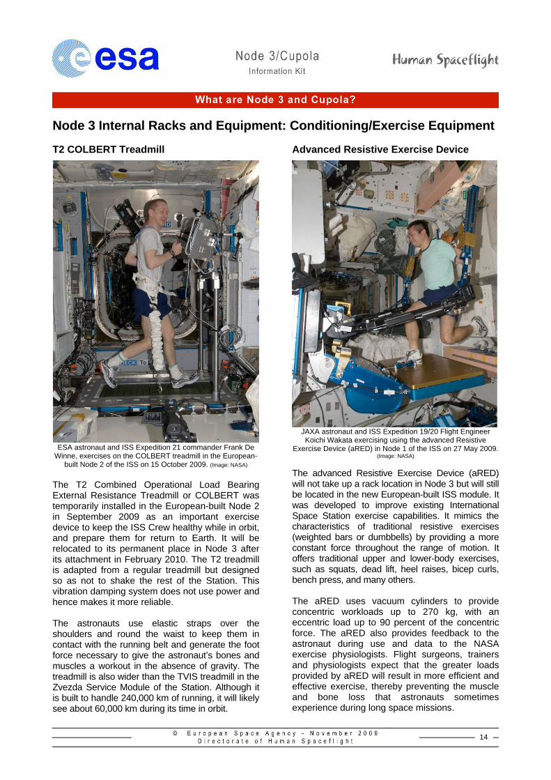
Node 3 Internal Racks and Equipment: Conditioning/Exercise Equipment T2 COLBERT Treadmill
ESA astronaut and ISS Expedition 21 commander Frank De
Winne, exercises on the COLBERT treadmill in the European-built Node 2 of the ISS on 15 October 2009. (Image: NASA)
The T2 Combined Operational Load Bearing External Resistance Treadmill or COLBERT was temporarily installed in the European-built Node 2 in September 2009 as an important exercise device to keep the ISS Crew healthy while in orbit, and prepare them for return to Earth. It will be relocated to its permanent place in Node 3 after its attachment in February 2010. The T2 treadmill is adapted from a regular treadmill but designed so as not to shake the rest of the Station. This vibration damping system does not use power and hence makes it more reliable. The astronauts use elastic straps over the shoulders and round the waist to keep them in contact with the running belt and generate the foot force necessary to give the astronaut’s bones and muscles a workout in the absence of gravity. The treadmill is also wider than the TVIS treadmill in the Zvezda Service Module of the Station. Although it is built to handle 240,000 km of running, it will likely see about 60,000 km during its time in orbit.
Advanced Resistive Exercise Device
JAXA astronaut and ISS Expedition 19/20 Flight Engineer Koichi Wakata exercising using the advanced Resistive
Exercise Device (aRED) in Node 1 of the ISS on 27 May 2009. (Image: NASA)
The advanced Resistive Exercise Device (aRED) will not take up a rack location in Node 3 but will still be located in the new European-built ISS module. It was developed to improve existing International Space Station exercise capabilities. It mimics the characteristics of traditional resistive exercises (weighted bars or dumbbells) by providing a more constant force throughout the range of motion. It offers traditional upper and lower-body exercises, such as squats, dead lift, heel raises, bicep curls, bench press, and many others. The aRED uses vacuum cylinders to provide concentric workloads up to 270 kg, with an eccentric load up to 90 percent of the concentric force. The aRED also provides feedback to the astronaut during use and data to the NASA exercise physiologists. Flight surgeons, trainers and physiologists expect that the greater loads provided by aRED will result in more efficient and effective exercise, thereby preventing the muscle and bone loss that astronauts sometimes experience during long space missions.
15
Node 3 and Cupola on-orbit activation *
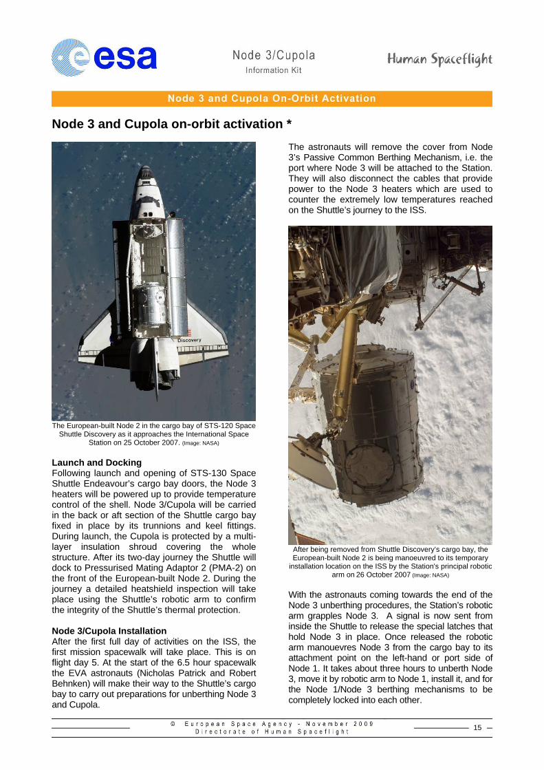
The European-built Node 2 in the cargo bay of STS-120 Space
Shuttle Discovery as it approaches the International Space Station on 25 October 2007. (Image: NASA)
Launch and Docking Following launch and opening of STS-130 Space Shuttle Endeavour’s cargo bay doors, the Node 3 heaters will be powered up to provide temperature control of the shell. Node 3/Cupola will be carried in the back or aft section of the Shuttle cargo bay fixed in place by its trunnions and keel fittings. During launch, the Cupola is protected by a multi-layer insulation shroud covering the whole structure. After its two-day journey the Shuttle will dock to Pressurised Mating Adaptor 2 (PMA-2) on the front of the European-built Node 2. During the journey a detailed heatshield inspection will take place using the Shuttle’s robotic arm to confirm the integrity of the Shuttle’s thermal protection. Node 3/Cupola Installation After the first full day of activities on the ISS, the first mission spacewalk will take place. This is on flight day 5. At the start of the 6.5 hour spacewalk the EVA astronauts (Nicholas Patrick and Robert Behnken) will make their way to the Shuttle’s cargo bay to carry out preparations for unberthing Node 3 and Cupola.
The astronauts will remove the cover from Node 3’s Passive Common Berthing Mechanism, i.e. the port where Node 3 will be attached to the Station. They will also disconnect the cables that provide power to the Node 3 heaters which are used to counter the extremely low temperatures reached on the Shuttle’s journey to the ISS.
After being removed from Shuttle Discovery’s cargo bay, the European-built Node 2 is being manoeuvred to its temporary
installation location on the ISS by the Station's principal robotic arm on 26 October 2007 (Image: NASA)
With the astronauts coming towards the end of the Node 3 unberthing procedures, the Station’s robotic arm grapples Node 3. A signal is now sent from inside the Shuttle to release the special latches that hold Node 3 in place. Once released the robotic arm manouevres Node 3 from the cargo bay to its attachment point on the left-hand or port side of Node 1. It takes about three hours to unberth Node 3, move it by robotic arm to Node 1, install it, and for the Node 1/Node 3 berthing mechanisms to be completely locked into each other.
16
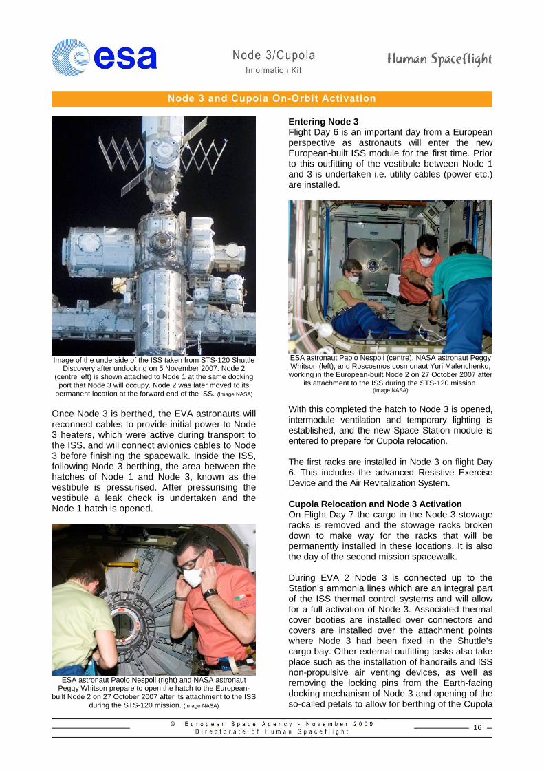
Image of the underside of the ISS taken from STS-120 Shuttle
Discovery after undocking on 5 November 2007. Node 2 (centre left) is shown attached to Node 1 at the same docking
port that Node 3 will occupy. Node 2 was later moved to its permanent location at the forward end of the ISS. (Image NASA)
Once Node 3 is berthed, the EVA astronauts will reconnect cables to provide initial power to Node 3 heaters, which were active during transport to the ISS, and will connect avionics cables to Node 3 before finishing the spacewalk. Inside the ISS, following Node 3 berthing, the area between the hatches of Node 1 and Node 3, known as the vestibule is pressurised. After pressurising the vestibule a leak check is undertaken and the Node 1 hatch is opened.
ESA astronaut Paolo Nespoli (right) and NASA astronaut
Peggy Whitson prepare to open the hatch to the European-built Node 2 on 27 October 2007 after its attachment to the ISS
during the STS-120 mission. (Image NASA)
Entering Node 3 Flight Day 6 is an important day from a European perspective as astronauts will enter the new European-built ISS module for the first time. Prior to this outfitting of the vestibule between Node 1 and 3 is undertaken i.e. utility cables (power etc.) are installed.
ESA astronaut Paolo Nespoli (centre), NASA astronaut Peggy Whitson (left), and Roscosmos cosmonaut Yuri Malenchenko, working in the European-built Node 2 on 27 October 2007 after
its attachment to the ISS during the STS-120 mission. (Image NASA)
With this completed the hatch to Node 3 is opened, intermodule ventilation and temporary lighting is established, and the new Space Station module is entered to prepare for Cupola relocation. The first racks are installed in Node 3 on flight Day 6. This includes the advanced Resistive Exercise Device and the Air Revitalization System. Cupola Relocation and Node 3 Activation On Flight Day 7 the cargo in the Node 3 stowage racks is removed and the stowage racks broken down to make way for the racks that will be permanently installed in these locations. It is also the day of the second mission spacewalk. During EVA 2 Node 3 is connected up to the Station’s ammonia lines which are an integral part of the ISS thermal control systems and will allow for a full activation of Node 3. Associated thermal cover booties are installed over connectors and covers are installed over the attachment points where Node 3 had been fixed in the Shuttle’s cargo bay. Other external outfitting tasks also take place such as the installation of handrails and ISS non-propulsive air venting devices, as well as removing the locking pins from the Earth-facing docking mechanism of Node 3 and opening of the so-called petals to allow for berthing of the Cupola
17
at this docking port. At the end of the EVA 2, procedures are started to set-up Node 3 as a fully functioning element of ISS.
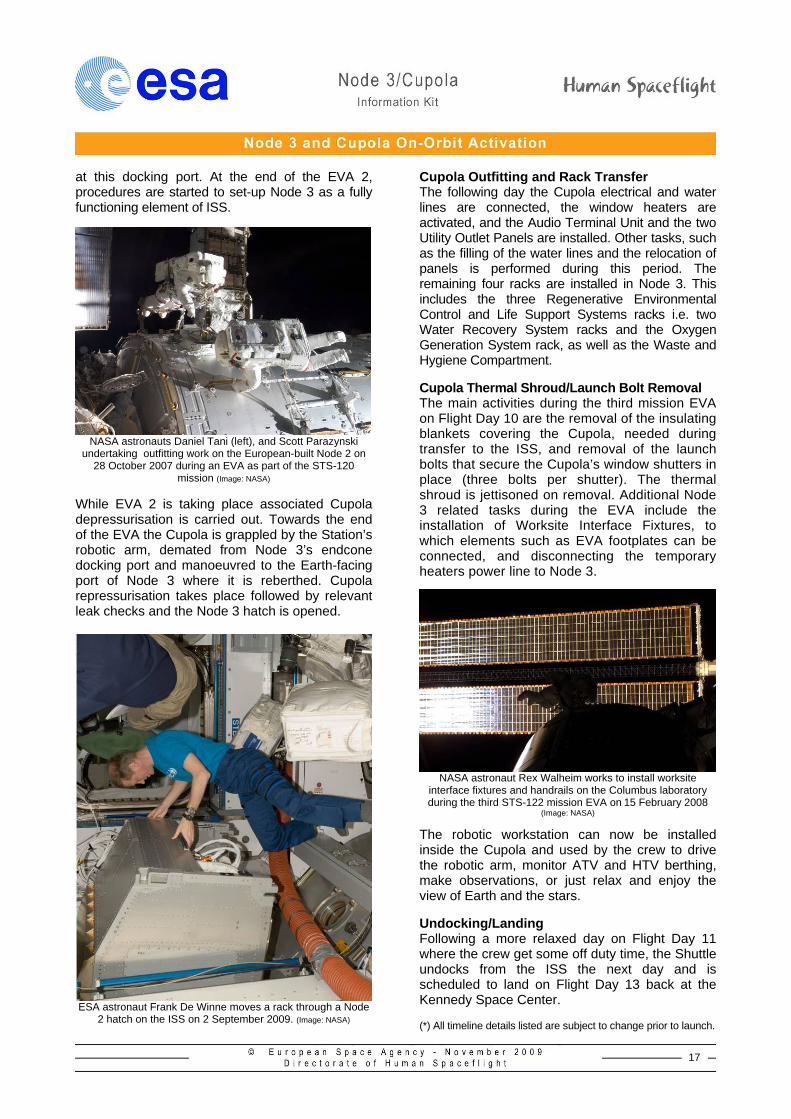
NASA astronauts Daniel Tani (left), and Scott Parazynski
undertaking outfitting work on the European-built Node 2 on 28 October 2007 during an EVA as part of the STS-120
mission (Image: NASA) While EVA 2 is taking place associated Cupola depressurisation is carried out. Towards the end of the EVA the Cupola is grappled by the Station’s robotic arm, demated from Node 3’s endcone docking port and manoeuvred to the Earth-facing port of Node 3 where it is reberthed. Cupola repressurisation takes place followed by relevant leak checks and the Node 3 hatch is opened.
ESA astronaut Frank De Winne moves a rack through a Node
2 hatch on the ISS on 2 September 2009. (Image: NASA)
Cupola Outfitting and Rack Transfer The following day the Cupola electrical and water lines are connected, the window heaters are activated, and the Audio Terminal Unit and the two Utility Outlet Panels are installed. Other tasks, such as the filling of the water lines and the relocation of panels is performed during this period. The remaining four racks are installed in Node 3. This includes the three Regenerative Environmental Control and Life Support Systems racks i.e. two Water Recovery System racks and the Oxygen Generation System rack, as well as the Waste and Hygiene Compartment. Cupola Thermal Shroud/Launch Bolt Removal The main activities during the third mission EVA on Flight Day 10 are the removal of the insulating blankets covering the Cupola, needed during transfer to the ISS, and removal of the launch bolts that secure the Cupola’s window shutters in place (three bolts per shutter). The thermal shroud is jettisoned on removal. Additional Node 3 related tasks during the EVA include the installation of Worksite Interface Fixtures, to which elements such as EVA footplates can be connected, and disconnecting the temporary heaters power line to Node 3.
NASA astronaut Rex Walheim works to install worksite
interface fixtures and handrails on the Columbus laboratory during the third STS-122 mission EVA on 15 February 2008
(Image: NASA)
The robotic workstation can now be installed inside the Cupola and used by the crew to drive the robotic arm, monitor ATV and HTV berthing, make observations, or just relax and enjoy the view of Earth and the stars. Undocking/Landing Following a more relaxed day on Flight Day 11 where the crew get some off duty time, the Shuttle undocks from the ISS the next day and is scheduled to land on Flight Day 13 back at the Kennedy Space Center. (*) All timeline details listed are subject to change prior to launch.
18
ISS Intergovernmental Agreement
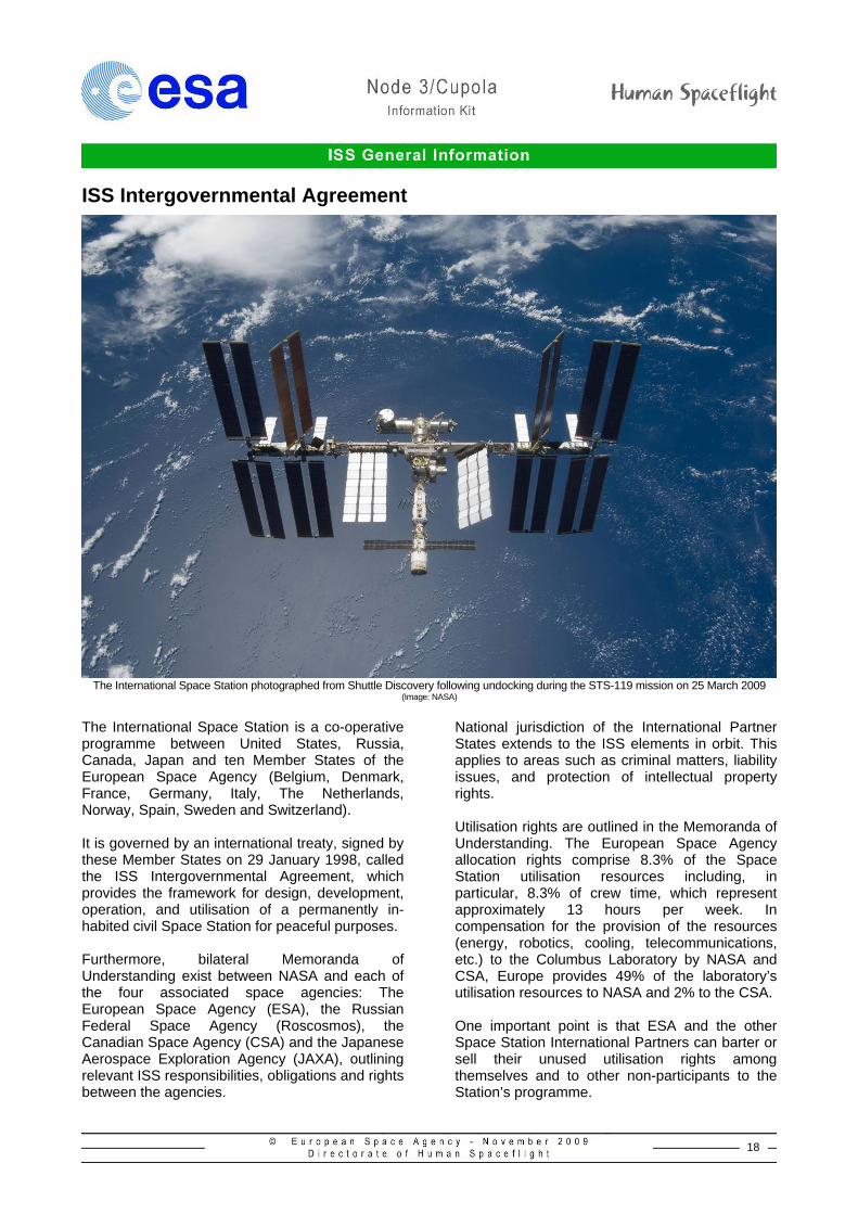
The International Space Station photographed from Shuttle Discovery following undocking during the STS-119 mission on 25 March 2009
(Image: NASA)
The International Space Station is a co-operative programme between United States, Russia, Canada, Japan and ten Member States of the European Space Agency (Belgium, Denmark, France, Germany, Italy, The Netherlands, Norway, Spain, Sweden and Switzerland). It is governed by an international treaty, signed by these Member States on 29 January 1998, called the ISS Intergovernmental Agreement, which provides the framework for design, development, operation, and utilisation of a permanently in-habited civil Space Station for peaceful purposes. Furthermore, bilateral Memoranda of Understanding exist between NASA and each of the four associated space agencies: The European Space Agency (ESA), the Russian Federal Space Agency (Roscosmos), the Canadian Space Agency (CSA) and the Japanese Aerospace Exploration Agency (JAXA), outlining relevant ISS responsibilities, obligations and rights between the agencies.
National jurisdiction of the International Partner States extends to the ISS elements in orbit. This applies to areas such as criminal matters, liability issues, and protection of intellectual property rights. Utilisation rights are outlined in the Memoranda of Understanding. The European Space Agency allocation rights comprise 8.3% of the Space Station utilisation resources including, in particular, 8.3% of crew time, which represent approximately 13 hours per week. In compensation for the provision of the resources (energy, robotics, cooling, telecommunications, etc.) to the Columbus Laboratory by NASA and CSA, Europe provides 49% of the laboratory’s utilisation resources to NASA and 2% to the CSA. One important point is that ESA and the other Space Station International Partners can barter or sell their unused utilisation rights among themselves and to other non-participants to the Station’s programme.
19
ISS and Europe’s Major Contributions
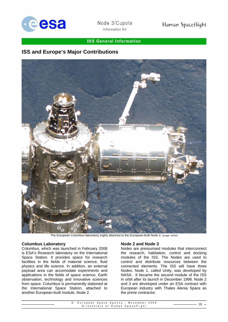
The European Columbus laboratory (right) attached to the European-built Node 2. (Image: NASA)
Columbus Laboratory Columbus, which was launched in February 2008 is ESA’s Research laboratory on the International Space Station. It provides space for research facilities in the fields of material science, fluid physics and life science. In addition, an external payload area can accomodate experiments and applications in the fields of space science, Earth observation, technology and innovative sciences from space. Columbus is permanently stationed at the International Space Station, attached to another European-built module, Node 2.
Node 2 and Node 3 Nodes are pressurised modules that interconnect the research, habitation, control and docking modules of the ISS. The Nodes are used to control and distribute resources between the connected elements. The ISS will have three Nodes. Node 1, called Unity, was developed by NASA. It became the second module of the ISS in orbit after its launch in December 1998. Node 2 and 3 are developed under an ESA contract with European industry with Thales Alenia Space as the prime contractor.
20
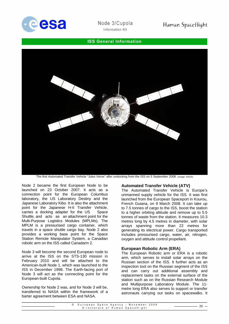
The first Automated Transfer Vehicle “Jules Verne” after undocking from the ISS on 5 September 2008. (Image: NASA)
Node 2 became the first European Node to be launched on 23 October 2007. It acts as a connection point for the European Columbus laboratory, the US Laboratory Destiny and the Japanese Laboratory Kibo. It is also the attachment point for the Japanese H-II Transfer Vehicle, carries a docking adapter for the US Space Shuttle, and acts as an attachment point for the Multi-Purpose Logistics Modules (MPLMs). The MPLM is a pressurised cargo container, which travels in a space shuttle cargo bay. Node 2 also provides a working base point for the Space Station Remote Manipulator System, a Canadian robotic arm on the ISS called Canadarm 2. Node 3 will become the second European node to arrive at the ISS on the STS-130 mission in February 2010 and will be attached to the American-built Node 1, which was launched to the ISS in December 1998. The Earth-facing port of Node 3 will act as the connecting point for the European-built Cupola. Ownership for Node 2 was, and for Node 3 will be, transferred to NASA within the framework of a barter agreement between ESA and NASA.
Automated Transfer Vehicle (ATV) The Automated Transfer Vehicle is Europe’s unmanned supply vehicle for the ISS. It was first launched from the European Spaceport in Kourou, French Guiana, on 9 March 2008. It can take up to 7.5 tonnes of cargo to the ISS, boost the station to a higher orbiting altitude and remove up to 5.5 tonnes of waste from the station. It measures 10.3 metres long by 4.5 metres in diameter, with solar arrays spanning more than 22 metres for generating its electrical power. Cargo transported includes pressurised cargo, water, air, nitrogen, oxygen and attitude control propellant. European Robotic Arm (ERA) The European Robotic arm or ERA is a robotic arm, which serves to install solar arrays on the Russian section of the ISS. It further acts as an inspection tool on the Russian segment of the ISS and can carry out additional assembly and replacement tasks on the external surface of the station such as on the Russian Research Module and Multipurpose Laboratory Module. The 11-metre long ERA also serves to support or transfer astronauts carrying out tasks on spacewalks. It
21
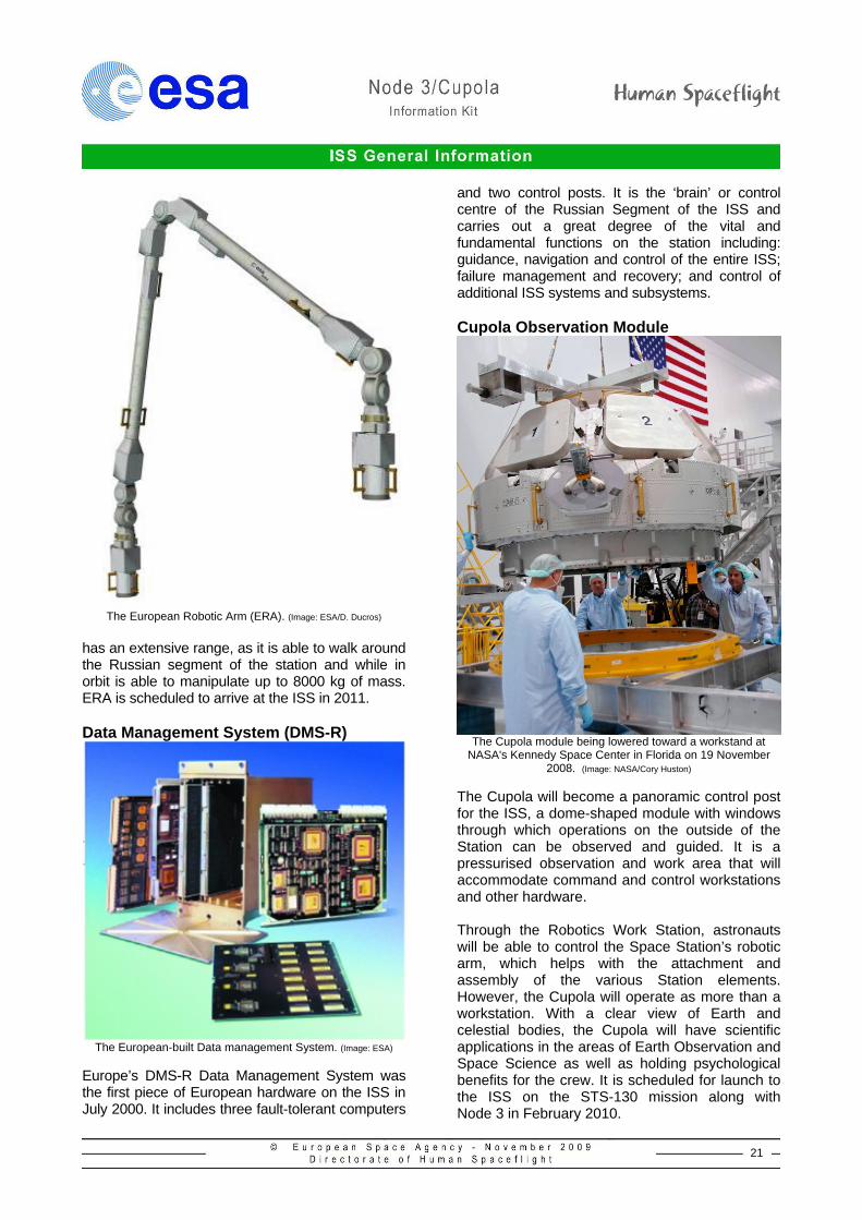
The European Robotic Arm (ERA). (Image: ESA/D. Ducros)
has an extensive range, as it is able to walk around the Russian segment of the station and while in orbit is able to manipulate up to 8000 kg of mass. ERA is scheduled to arrive at the ISS in 2011. Data Management System (DMS-R)
The European-built Data management System. (Image: ESA)
Europe’s DMS-R Data Management System was the first piece of European hardware on the ISS in July 2000. It includes three fault-tolerant computers
and two control posts. It is the ‘brain’ or control centre of the Russian Segment of the ISS and carries out a great degree of the vital and fundamental functions on the station including: guidance, navigation and control of the entire ISS; failure management and recovery; and control of additional ISS systems and subsystems. Cupola Observation Module
The Cupola module being lowered toward a workstand at
NASA's Kennedy Space Center in Florida on 19 November 2008. (Image: NASA/Cory Huston)
The Cupola will become a panoramic control post for the ISS, a dome-shaped module with windows through which operations on the outside of the Station can be observed and guided. It is a pressurised observation and work area that will accommodate command and control workstations and other hardware. Through the Robotics Work Station, astronauts will be able to control the Space Station’s robotic arm, which helps with the attachment and assembly of the various Station elements. However, the Cupola will operate as more than a workstation. With a clear view of Earth and celestial bodies, the Cupola will have scientific applications in the areas of Earth Observation and Space Science as well as holding psychological benefits for the crew. It is scheduled for launch to the ISS on the STS-130 mission along with Node 3 in February 2010.
22
Credits This document has been compiled, produced and written by the Coordination Office of the European Space Agency’s Directorate of Human Spaceflight in Noordwijk, The Netherlands. It has been compiled from internal ESA sources with additional images and information kindly supplied by the following organisations: National Aeronautics and Space Administration (NASA) Russian Federal Space Agency (Roscosmos) Japanese Aerospace Exploration Agency (JAXA)
Contacts European Space Agency (ESA) Directorate of Human Spaceflight ESTEC, Keplerlaan 1, PO Box 299 2200 AG Noordwijk, The Netherlands. Tel: +31 (0) 71 565 6799 Fax: +31 (0) 71 565 5441 www.esa.int/spaceflight ESA Media Relations ESA Head Office, Paris, France. Tel. + 33 1 5369 7155 Fax. + 33 1 5369 7690 [email protected] National Aeronautics and Space Administration (NASA) http://www.nasa.gov Russian Federal Space Agency, (Roscosmos) http://www.roscosmos.ru/index.asp?Lang=ENG Japanese Aerospace Exploration Agency http://www.jaxa.jp/index_e.html