Embed Size (px)
Citation preview

!
Installation & Calibration Manual
ED3/ED4-EP SkidWeigh Plus Series Electric Pallet Truck Check Weighing Lift Accurate Technology
ED3/ED4-EP V118
Integrated Visual Data Technology Inc. 3439 Whilabout Terrace, Oakville, Ontario, Canada L6L 0A7 www.skidweigh.com

!
General Installation Guide
This ED3-EP and ED4-EP SkidWeigh Plus V118 Series installation & calibration guide describes how to install, calibrate, test and use your on-board check weighing unit. Following the instructions in the ADMINISTRATION MENU guide will enable you to get the system set up and weighing calibration function operating quickly. In the event that you require additional assistance, please contact customer support via e-mail at [email protected] , visit www.skidweigh.com or contact us at the address or contact number below:
Integrated Visual Data Technology Inc. 3439 Whilabout Terrace, Oakville, ON, Canada, L6L 0A7 Phone: 905-469-0985
Safety Always disconnect the vehicle battery while installing SkidWeigh system or any other electronic product. Make sure that unit, pressure transducer and any other associated cables are securely mounted and do not impede any of the vehicle’s controls. Use care when routing the components cables. Route the cables where they will be protected. Use commonly accepted install practices for after market industrial vehicle electronic devices. The installation of the SkidWeigh systems should only be performed by an acknowledged lift truck dealer technician or end user electro and hydraulic technical installer. Here are two acceptable methods of making a wire connections: * Soldering your connections (recommended) * Crimp connectors ( with the use of the proper crimping tool) Regardless of the method you choose, ensure that the connection is mechanically sound and properly insulated. Use high quality electrical tape and shrink tubing where necessary. This product is connected directly to the vehicle’s ignition switch, 12 to 55 VDC. There is no on-off switch on the unit.
Electro-Magnetic Compatibility CE conformity to EC directive 89/336 (EMC) by application of harmonized standards: Interference stability EN 61000-6-2 and EN 61326-1 interference emit EN 61000-6-3, EN 61326-1 for the pressure transducer.
ED3/ED4-EP SkidWeigh Plus Series Our policy is one of continuous improvement and the information in this document is subject to change without notice. The software version is displayed on the LCD display once the power is turned on to the system.
Overview of components The standard ED3/ED4-EP SkidWeigh Plus check weighing system consist of two main components: * Digital indicator with wiring harness, mounting bracket and anti-vibration mount * Hydraulic pressure transducer with 3 wires cable * Installation & calibration manual and operator usage instruction
Integrated Visual Data Technology Inc. 3439 Whilabout Terrace, Oakville, Ontario, Canada L6L 0A7 www.skidweigh.com
!
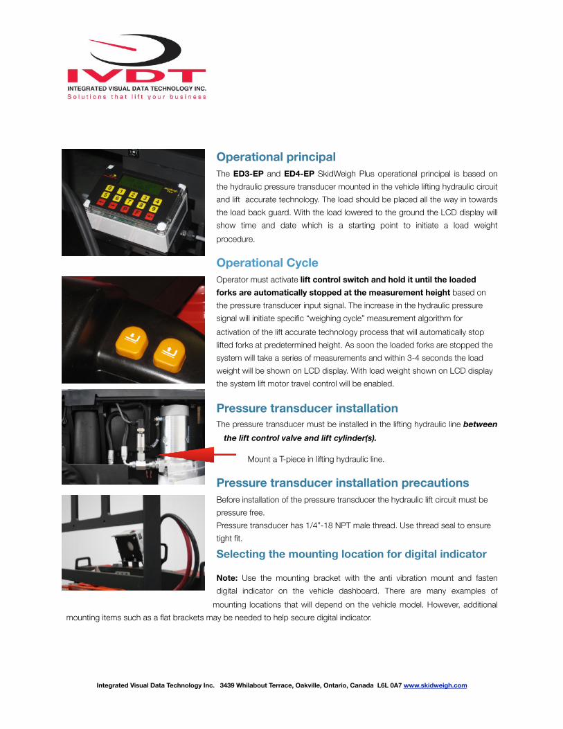
Operational principal The ED3-EP and ED4-EP SkidWeigh Plus operational principal is based on the hydraulic pressure transducer mounted in the vehicle lifting hydraulic circuit and lift accurate technology. The load should be placed all the way in towards the load back guard. With the load lowered to the ground the LCD display will show time and date which is a starting point to initiate a load weight procedure.
Operational Cycle
Operator must activate lift control switch and hold it until the loaded forks are automatically stopped at the measurement height based on the pressure transducer input signal. The increase in the hydraulic pressure signal will initiate specific “weighing cycle” measurement algorithm for activation of the lift accurate technology process that will automatically stop lifted forks at predetermined height. As soon the loaded forks are stopped the system will take a series of measurements and within 3-4 seconds the load weight will be shown on LCD display. With load weight shown on LCD display the system lift motor travel control will be enabled.
Pressure transducer installation The pressure transducer must be installed in the lifting hydraulic line between
the lift control valve and lift cylinder(s).
Mount a T-piece in lifting hydraulic line.
Pressure transducer installation precautions Before installation of the pressure transducer the hydraulic lift circuit must be pressure free. Pressure transducer has 1/4”-18 NPT male thread. Use thread seal to ensure tight fit.
Selecting the mounting location for digital indicator
Note: Use the mounting bracket with the anti vibration mount and fasten digital indicator on the vehicle dashboard. There are many examples of
mounting locations that will depend on the vehicle model. However, additional mounting items such as a flat brackets may be needed to help secure digital indicator.
Integrated Visual Data Technology Inc. 3439 Whilabout Terrace, Oakville, Ontario, Canada L6L 0A7 www.skidweigh.com

!
Electrical connections All SkidWeigh systems operate from 12 to 55 VDC. - Orange Wire (+) Ignition switch On position - Brown Wire (-) Battery negative - Red Wire, connect to RED wire of the pressure transducer cable - Black Wire, connect to BLACK wire of the pressure transducer cable - White Wire, connect to WHITE wire of the pressure transducer cable
Two Black wires are connected to internal relay, dry contacts located in ED3/ED4-EP digital indicator. This internal relay is controlled by the microprocessor and will be activated only during the load weighing cycle. The relay configuration is SPST, normally closed NC contacts. 10 A current ratting
Pressure transducer
Power short circuit protection
All SkidWeigh systems are internally short circuit protected with resettable fuse. There is no need to install external inline fuse in orange wire connected to the ignition switch. Note: Any external devices connected to the SkidWeigh system, such as non standard onboard printer might require external fuse.
Verification of the electrical connections done properly Note: SkidWeigh weighing calibration function is not done at this stage. This test procedure is only to check if the electrical connections of the system installation into the vehicle is done properly! - Turn on vehicle power switch - Lower forks to ground - Turn on digital indicator power switch located on top of the housing - Digital LCD display will be activated, showing software version and serial number - Digital LCD display will show current date and time
LCD Display
Aug 28, 2010
12:20:23
Integrated Visual Data Technology Inc. 3439 Whilabout Terrace, Oakville, Ontario, Canada L6L 0A7 www.skidweigh.com
Male Port 1/4”-18 NPT

!
If the forks are lifted above the ground LCD digital display will show “PLEASE WAIT” and within few seconds display will show “some” load weight . (Example: 455, not calibrated load weight at this stage)
If the above test is valid than the system electrical connections are done right. The next procedure will be to log in the ADMINISTRATION MENU to calibrate the weighing function.
LCD Display
PLEASE WEIGHT
WEIGHT = 455
Integrated Visual Data Technology Inc. 3439 Whilabout Terrace, Oakville, Ontario, Canada L6L 0A7 www.skidweigh.com
!
Integrated Visual Data Technology Inc. 3439 Whilabout Terrace, Oakville, Ontario, Canada L6L 0A7 www.skidweigh.com
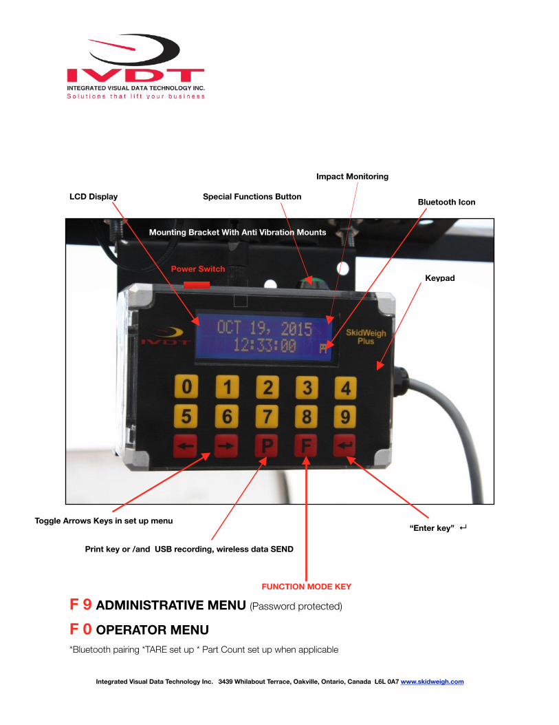
LCD Display Special Functions Button Bluetooth Icon
Keypad
“Enter key” ↵Toggle Arrows Keys in set up menu
Print key or /and USB recording, wireless data SEND
FUNCTION MODE KEY
F 9 ADMINISTRATIVE MENU (Password protected)
F 0 OPERATOR MENU
*Bluetooth pairing *TARE set up * Part Count set up when applicable
Impact Monitoring
Mounting Bracket With Anti Vibration Mounts
Power Switch
!
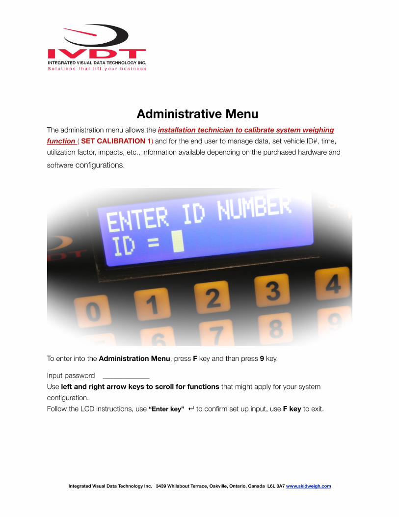
Administrative Menu The administration menu allows the installation technician to calibrate system weighing function ( SET CALIBRATION 1) and for the end user to manage data, set vehicle ID#, time, utilization factor, impacts, etc., information available depending on the purchased hardware and software configurations.
To enter into the Administration Menu, press F key and than press 9 key.
Input password _____________ Use left and right arrow keys to scroll for functions that might apply for your system configuration. Follow the LCD instructions, use “Enter key” ↵ to confirm set up input, use F key to exit.
Integrated Visual Data Technology Inc. 3439 Whilabout Terrace, Oakville, Ontario, Canada L6L 0A7 www.skidweigh.com
!
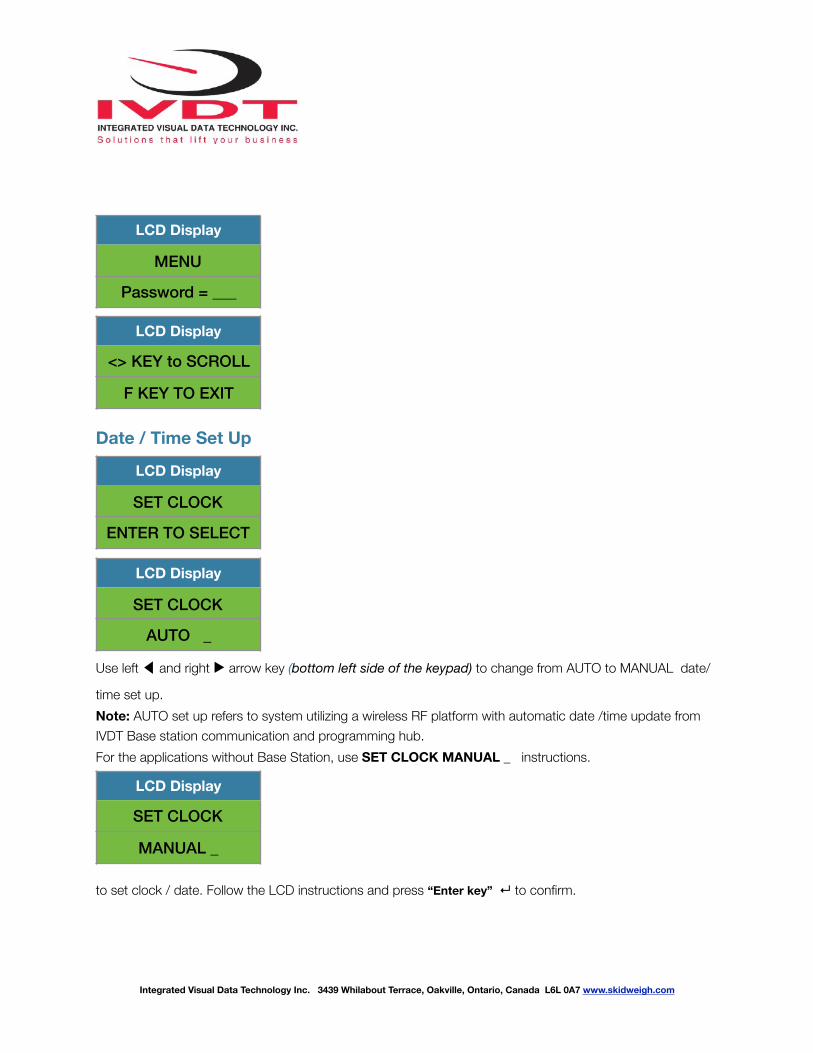
Date / Time Set Up
Use left ◀ and right ▶ arrow key (bottom left side of the keypad) to change from AUTO to MANUAL date/
time set up. Note: AUTO set up refers to system utilizing a wireless RF platform with automatic date /time update from IVDT Base station communication and programming hub. For the applications without Base Station, use SET CLOCK MANUAL _ instructions.
to set clock / date. Follow the LCD instructions and press “Enter key” ↵ to confirm.
LCD Display
MENU
Password = ___
LCD Display
<> KEY to SCROLL
F KEY TO EXIT
LCD Display
SET CLOCK
ENTER TO SELECT
LCD Display
SET CLOCK
AUTO _
LCD Display
SET CLOCK
MANUAL _
Integrated Visual Data Technology Inc. 3439 Whilabout Terrace, Oakville, Ontario, Canada L6L 0A7 www.skidweigh.com

!
Press “Enter key” ↵ to confirm the setting. The cursor will automatically move to the next item to be changed
( Month, Day, Year, Hours, Minutes, Seconds). On the last correction, seconds item press “Enter key” ↵ to confirm
new date / time set up.
Set vehicle ID# - Maximum input number for vehicle ID# is 4 digits. Note: For system used with RFID card reader maximum input number for vehicle ID# is 5 digits.
LCD Display
Aug 28, 2010
12:20:23
LCD Display
<> KEY to SCROLL
F KEY TO EXIT
LCD Display
SET VEHICLE ID
ENTER TO SELECT
LCD Display
ENTER VEHICLE ID
1_
LCD Display
VEHICLE ID
CONFIGURATED
Integrated Visual Data Technology Inc. 3439 Whilabout Terrace, Oakville, Ontario, Canada L6L 0A7 www.skidweigh.com

!
Lift Accurate Technology
Automatic lift motor travel de-activation methods during the load weighing cycle
Two BLACK wires are connected to the internal relay, dry contacts located in the ED3/ED4-EP digital indicator. This internal relay is controlled by the microprocessor and activate only during the load weigh-ing cycle. There is no power connected to these two BLACK wires. Internal relay configuration is SPST normally closed contacts,10 A current rating.
Method A. (Newer electric pallet trucks with various CANbus controllers) Use two BLACK wires and “splice” them in series with the operator activated lift control switch wire
or signal wire from electronic controller that is activating lift up valve lift motor solenoid. The predeter-
mined motion of the lifting cylinder and the load weight measurement “weighing cycle” will be initiated
and controlled automatically by the software algorithm based on the input from the pressure transducer
signal. Once the load weight is shown on the LCD display internal relay will be de-activated and the lift
motion control event will be automatically enable.
(With vehicle stationary and during the lifting cycle diagnostic display on some vehicles might show “No
power to lift motor” or audio signal might be activated for short time period.)
Consult vehicle wiring diagram or contact the OEM for the proper interface to control lift motor control
Integrated Visual Data Technology Inc. 3439 Whilabout Terrace, Oakville, Ontario, Canada L6L 0A7 www.skidweigh.com
!
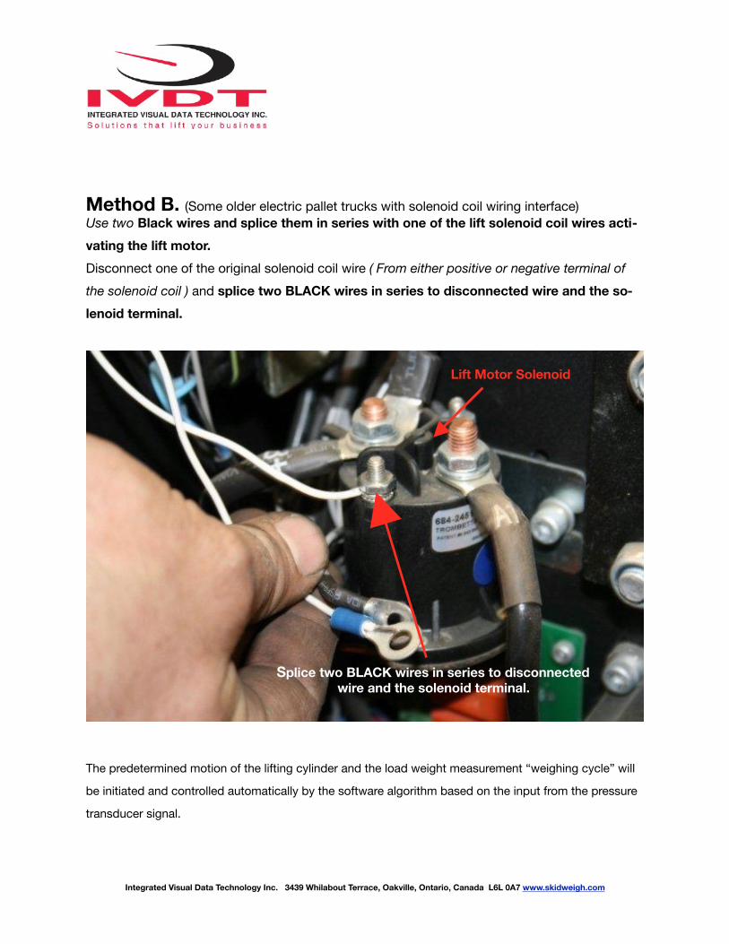
Method B. (Some older electric pallet trucks with solenoid coil wiring interface)Use two Black wires and splice them in series with one of the lift solenoid coil wires acti-vating the lift motor. Disconnect one of the original solenoid coil wire ( From either positive or negative terminal of the solenoid coil ) and splice two BLACK wires in series to disconnected wire and the so-lenoid terminal.
The predetermined motion of the lifting cylinder and the load weight measurement “weighing cycle” will
be initiated and controlled automatically by the software algorithm based on the input from the pressure
transducer signal.
Integrated Visual Data Technology Inc. 3439 Whilabout Terrace, Oakville, Ontario, Canada L6L 0A7 www.skidweigh.com
Lift Motor Solenoid
Splice two BLACK wires in series to disconnected wire and the solenoid terminal.
!
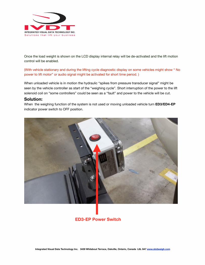
Once the load weight is shown on the LCD display internal relay will be de-activated and the lift motion control will be enabled.
(With vehicle stationary and during the lifting cycle diagnostic display on some vehicles might show “ No power to lift motor” or audio signal might be activated for short time period. )
When unloaded vehicle is in motion the hydraulic “spikes from pressure transducer signal” might be seen by the vehicle controller as start of the “weighing cycle”. Short interruption of the power to the lift solenoid coil on “some controllers” could be seen as a “fault” and power to the vehicle will be cut.
Solution: When the weighing function of the system is not used or moving unloaded vehicle turn ED3/ED4-EP indicator power switch to OFF position.
Integrated Visual Data Technology Inc. 3439 Whilabout Terrace, Oakville, Ontario, Canada L6L 0A7 www.skidweigh.com
ED3-EP Power Switch

!
Weighing scale function calibration The ED3/ED4-EP SkidWeigh Plus calibration is automatic and is done by lifting empty and loaded forks with known load weight. MAKE SURE THAT YOU HAVE A KNOWN LOAD WEIGHT AND KEEP IT NEARBY TO COMPLETE THE CALIBRATION. For the best results use at least minimum calibration load test weight of 30 to 50% of maximum lifting capacity of the lift truck. Use customer floor scale or find a known skid load weight within the operational facility. Important: If you want the system to show load weight in pounds, use the known load weight in pounds and enter that value accordingly. The same would apply if you want the system to show load weight in kilograms. Use the known load weight in kilograms and enter that value into the system accordingly.
Calibration starting point Lower the empty forks to the ground. There should be no hydraulic pressure in lift hydraulic circuit. Follow instructions shown on the LCD display To enter into the Administration Menu, press F key and than press 9 key and input password _____________ Use left or right arrow keys to scroll to “CALIBRATION 1” menu. Press “Enter key” ↵ and follow the LCD instructions.
- Activate and hold lift motor control switch until lifted empty forks are automatically stopped.
LCD Display
<> KEY TO SCROLL
F KEY TO EXIT
LCD Display
CALIBRATION 1ENTER TO SELECT
LCD Display
CALIBRATION 1LIFT EMPTY FORKS
Integrated Visual Data Technology Inc. 3439 Whilabout Terrace, Oakville, Ontario, Canada L6L 0A7 www.skidweigh.com

!
System zero load value will be calibrated. After few seconds the LCD display will show
Lower the empty forks to the ground. The LCD display prompt you to input known calibration load weight.
Pick up a known load weigh and lower the loaded forks to the ground. (Our example of the known load weight is 2000 kg)
Input into the system the known load weight of 2000 into the LCD display and press “Enter key” ↵. The LCD display will show
Activate and hold lift motor control switch until lifted loaded forks are automatically stopped.
LCD Display
CALIBRATION 1
LOWER FORKS
LCD Display
CALIBRATION 1
WEIGHT = ❏
LCD Display
CALIBRATION 1
WEIGHT = 2000
LCD Display
CALIBRATION 1
LIFT LOAD
LCD Display
CALIBRATION 1
LOWER FORKS
Integrated Visual Data Technology Inc. 3439 Whilabout Terrace, Oakville, Ontario, Canada L6L 0A7 www.skidweigh.com
!
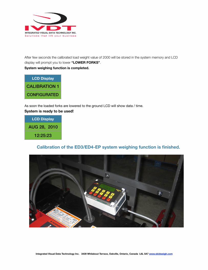
After few seconds the calibrated load weight value of 2000 will be stored in the system memory and LCD display will prompt you to lower “LOWER FORKS”. System weighing function is completed.
As soon the loaded forks are lowered to the ground LCD will show data / time. System is ready to be used!
Calibration of the ED3/ED4-EP system weighing function is finished.
LCD Display
CALIBRATION 1
CONFIGURATED
LCD Display
AUG 28, 2010
12:25:23
Integrated Visual Data Technology Inc. 3439 Whilabout Terrace, Oakville, Ontario, Canada L6L 0A7 www.skidweigh.com

!
Saving recorded data to USB memory stick
The ED3/ED4-EP SkidWeigh Plus system will allow you to download all recorded data to the memory stick. Follow instructions shown on the LCD displayThis function is located in Administrative Menu.
When the system has finished uploading the data to the USB memory stick the LCD display will prompt you to erase the SDRAM , all files contained on the SKidWeigh Plus ED3-EP. Once you have made your selection Y or N press “Enter key” ↵ to confirm selection and the system will automatically bring you back to the main
screen in the administrator menu. Press F key to exit the menu.
LCD Display
<> KEY TO SCROLL
F KEY TO EXIT
LCD Display
SAVE TO USB
ENTER TO SELECT
LCD Display
SAVING TO USB
—————-
LCD Display
ERASE SDRAM ? N
LCD Display
<> KEY TO SCROLL
F KEY TO EXIT
Integrated Visual Data Technology Inc. 3439 Whilabout Terrace, Oakville, Ontario, Canada L6L 0A7 www.skidweigh.com
!
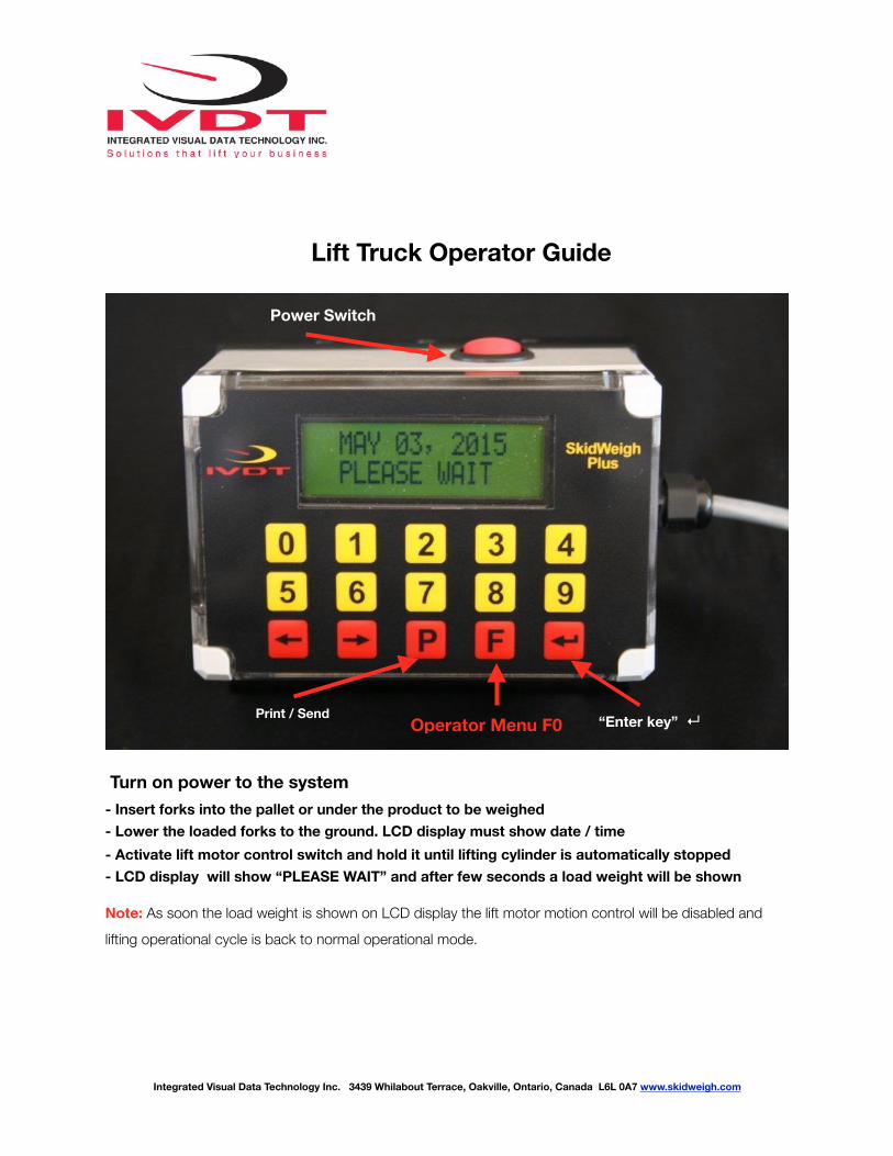
Lift Truck Operator Guide
Turn on power to the system - Insert forks into the pallet or under the product to be weighed - Lower the loaded forks to the ground. LCD display must show date / time - Activate lift motor control switch and hold it until lifting cylinder is automatically stopped - LCD display will show “PLEASE WAIT” and after few seconds a load weight will be shown
Note: As soon the load weight is shown on LCD display the lift motor motion control will be disabled and lifting operational cycle is back to normal operational mode.
Integrated Visual Data Technology Inc. 3439 Whilabout Terrace, Oakville, Ontario, Canada L6L 0A7 www.skidweigh.com
Power Switch
Print / Send “Enter key” ↵Operator Menu F0
Type to enter text

!
Integrated Visual Data Technology Inc. 3439 Whilabout Terrace, Oakville, Ontario, Canada L6L 0A7 www.skidweigh.com
“P” key Functions - Systems with USB port by pressing “P” key load weight data will be recorded and can
be downloaded to the memory stick at any time - Systems utilizing RF wireless module by pressing “P” key load weight will be send to
the base station Accumulative Load Weight Total - With LCD display showing load weight by pressing “Enter key” ↵ the current value will be added into total counter. You can keep adding individual loads and when finished by pressing “P” key the accumulative load weight total will be printed, recorded or send to the base station. Waybill ID# - With Waybill ID# function enabled by pressing “P” key you will be able to input valid Waybill ID number.
Operator Menu (Pressing F key and than pressing number 0)
- Depending on the system configuration the operator menu by pressing F key and than pressing 0 key allows operator to do a following: BLUETOOTH PAIRING (Systems with onboard printer or scanner) TARE function (Input of Tare value when using the weighing function) PARTS COUNT by weight (Input for individual part weight)