Embed Size (px)
Citation preview
TAKE A GOOD LOOK
CALL BUTTON• Takeacallorendit (1 tap)• Redial(2 taps)• Reconnectlostconnection(1 tap)• Activatepairingafterinitialsetup
(press until LED flashes blue/red)• Transferacallto/fromheadset
(1-second press during call)
POWER SWITCH• On (slide to reveal black)• Off (slide to reveal red)
VOICE RECOGNITION BUTTON• VoiceRecognition(VR)commands
(Tap VR button, say a command within 10 seconds. See Voice Com-mands for commands list.)
• Initiatephone’svoice-dialing (2-taps then tone heard)
MICRO USB CHARGING PORT• WithACcharger: 20 minutes (1 hour talk time) Less than 2 hours (full charge)• Bestperformancewhenfullycharged
VOLUME/MUTE BUTTON• Volumeup/down (1 tap per level
change)• Mute:on/off (1-second press)
LED• Charging (Solid red. No light when
fully charged)• Lowbattery (2 red flashes, 2 tones
and voice alert)• Criticallylow (3 red flashes, 3 tones
and voice alert)
Besafe!Please read the safety guide before using your new headset.
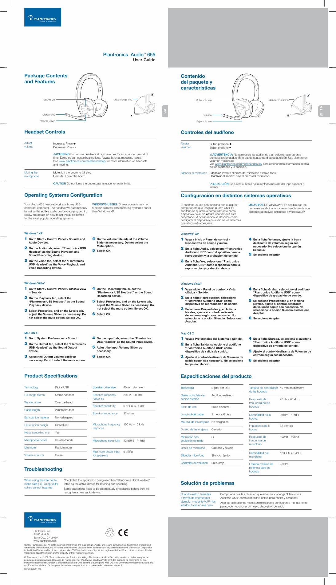
Plantronics .Audio™ 655 User Guide
Package Contents and Features
Volume Up Mute Microphone
Volume Down
Microphone
Operating Systems Configuration
Your .Audio 655 headset works with any USB-compliant computer. The headset will automatically be set as the active audio device once plugged in. Below are details on how to set the audio device for the most popular operating systems.
WINDOWS USERS: On-ear controls may not function properly with operating systerms earlier than Windows XP.
Windows Vista®
1 Go to Start > Control Panel > Classic View > Sounds.
2 On the Playback tab, select the “Plantronics USB Headset” as the Sound Playback device.
3 Select Properties, and on the Levels tab, adjust the Volume Slider as necessary. Do not select the mute option. Select OK.
4 On the Recording tab, select the “Plantronics USB Headset” as the Sound Recording device.
5 Select Properties, and on the Levels tab, adjust the Volume Slider as necessary. Do not select the mute option. Select OK.
6 Select OK.
Windows® XP
1 Go to Start > Control Panel > Sounds and Audio Devices.
2 On the Audio tab, select “Plantronics USB Headset” as the Sound Playback and Sound Recording device.
3 On the Voice tab, select the “Plantronics USB Headset” as the Voice Playback and Voice Recording device.
4 On the Volume tab, adjust the Volume Slider as necessary. Do not select the Mute option.
5 Select OK.
Mac OS X
1 Go to System Preferences > Sound.
2 On the Output tab, select the “Plantronics USB Headset” as the Sound Output device.
3 Adjust the Output Volume Slider as necessary. Do not select the mute option.
4 On the Input tab, select the “Plantronics USB Headset” as the Sound Input device.
5 Adjust the Input Volume Slider as necessary.
6 Select OK.
Headset Controls
Product Specifications
Technology Digital USB
Full range stereo Stereo headset
Wearing style Over the head
Cable length 2 meters/6 feet
Ear cushion material Non-allergenic
Ear cushion design Closed ear
Noise cancelling mic Yes
Microphone boom Rotates/bends
Mic mute FastMic mute
Volume controls On ear
Speaker driver size 40 mm diameter
Speaker frequency response
20 Hz—20 kHz
Speaker sensitivity 0 dBPa +/- 4 dB
Speaker impedance 32 ohms
Microphone frequency response
100 Hz—10 kHz
Microphone sensitivity 12 dBFS +/- 4dB
Maximum power input for speakers
9 dBPa
When using the internet to make calls (i.e., using VoIP), callers cannot hear me
Check that the application being used has “Plantronics USB Headset” listed as the active device for listening and speaking.
Some applictions need to be set manually or restarted before they will recognize a new audio device.
Troubleshooting
Plantronics, Inc.345 Encinal St.Santa Cruz, CA 95060www.plantronics.com
©2009 Plantronics, Inc. All rights reserved. Plantronics, the logo design, .Audio, and Sound Innovation are trademarks or registered trademarks of Plantronics, Inc. Windows and Windows Vista are either trademarks or registered trademarks of Microsoft Corporation in the United States and/or other countries. Mac OS X is a trademark of Apple, Inc. registered in the US and other countries. All other trademarks appearing herein are the property of their respective owners.
Adjust volume
Increase: Press +Decrease: Press -
WARNING Do not use headsets at high volumes for an extended period of time. Doing so can cause hearing loss. Always listen at moderate levels. See www.plantronics.com/healthandsafety for more information on headsets and hearing.
Muting the microphone
Mute: Lift the boom to full stop.Unmute: Lower the boom.
CAUtION Do not force the boom past its upper or lower limits.
en
es
_xl
© Plantronics, Inc., 2009. Tous droits réservés. Plantronics, le logo Plantronics, .Audio et Sound Innovation sont des marques de commerce ou des marques déposées de Plantronics, Inc. Windows et Windows Vista sont des marques de commerce ou des marques déposées de Microsoft Corporation aux États-Unis et dans d'autres pays. Mac OS X est une marque déposée de Apple, Inc. aux États-Unis et dans d'autres pays. Les autres marques sont la propriété de leur détenteur respectif.
38643-04 (11.09)
Contenido del paquete y características
Subir volumen Silenciar micrófono
Bajar volumen
de ruido
Configuración en distintos sistemas operativos
El audífono .Audio 655 funciona con cualquier computadora que tenga un puerto USB. El audífono se ajustará automáticamente como dispositivo de audio activo una vez que esté conectado. A continuación se describe cómo configurar el dispositivo de audio en los sistemas operativos más comunes.
USUARIOS DE WINDOWS: Es posible que los controles en el oído funcionen correctamente con sistemas operativos anteriores a Windows XP.
Windows Vista®
1 Vaya Inicio > Panel de control > Vista clásica > Sonido.
2 En la ficha Reproducción, seleccione “Plantronics Audifono USB” como dispositivo de reproducción de sonido.
3 Seleccione Propiedades y, en la ficha Niveles, ajuste el control deslizante de volumen según sea necesario. No seleccione la opción Silencio. Seleccione Aceptar.
4 En la ficha Grabar, seleccione el audífono “Plantronics Audifono USB” como dispositivo de grabación de sonido.
5 Seleccione Propiedades y, en la ficha Niveles, ajuste el control deslizante de volumen según sea necesario. No seleccione la opción Silencio. Seleccione Aceptar.
6 Seleccione Aceptar.
Windows® XP
1 Vaya a Inicio > Panel de control > Dispositivos de sonido y audio.
2 En la ficha Audio, seleccione “Plantronics Audifono USB” como dispositivo para la reproducción y la grabación de sonido.
3 En la ficha Voz, seleccione “Plantronics Audifono USB” como dispositivo para la reproducción y grabación de voz.
4 En la ficha Volumen, ajuste la barra deslizante de volumen según sea necesario. No seleccione la opción Silencio.
5 Seleccione Aceptar.
Mac OS X
1 Vaya a Preferencias del Sistema > Sonido.
2 En la ficha Salida, seleccione el audífono “Plantronics Audifono USB” como dispositivo de salida de sonido.
3 Ajuste el control deslizante de Volumen de salida según sea necesario. No seleccione la opción Silencio.
4 En la ficha Entrada, seleccione el audífono “Plantronics Audifono USB” como dispositivo de entrada de sonido.
5 Ajuste el control deslizante de Volumen de entrada según sea necesario.
6 Seleccione Aceptar.
Controles del audífono
Especificaciones del producto
Tecnología Digital por USB
Gama completa de sonido estéreo
Audífono estéreo
Estilo de uso Estilo diadema
Longitud del cable 2 metros/6 pies
Material de las orejeras No alergénico
Diseño de las orejeras Cerrado
Micrófono con anulación de ruido
Sí
Brazo de micrófono Giratorio y flexible
Silenciar micrófono Silencio rápido
Controles de volumen En la oreja
Tamaño del controlador de las bocinas
40 mm de diámetro
Respuesta de frecuencia de las bocinas
20 Hz - 20 kHz
Sensibilidad de la bocina
0dBPa +/- 4dB
Impedancia de la bocina
32 ohmios
Respuesta de frecuencia del micrófono
100Hz—10kHz
Sensibilidad del micrófono
12dBFS +/- 4dB
Entrada máxima de potencia para las bocinas
9dBPa
Cuando realizo llamadas a través de Internet (por ejemplo, mediante VoIP), los interlocutores no me oyen.
Compruebe que la aplicación que está usando tenga “Plantronics Audifono USB" como dispositivo activo para hablar y escuchar.
Algunas aplicaciones necesitan reiniciarse o configurarse manualmente para poder reconocer un nuevo dispositivo de audio.
Solución de problemas
Ajustar volumen
Subir: presione +Bajar: presione -
ADVERtENCIA: No use nunca los audífonos a un volumen alto durante periodos prolongados. Esto puede causar pérdida de audición. Use siempre un volumen moderado. Vea www.plantronics.com/healthandsafety para obtener más información acerca de los audífonos y la audición.
Silenciar el micrófono Silenciar: levante el brazo del micrófono hasta el tope.Reactivar el sonido: baje el brazo del micrófono.
PRECAUCIóN No fuerce el brazo del micrófono más allá del tope superior o inferior.
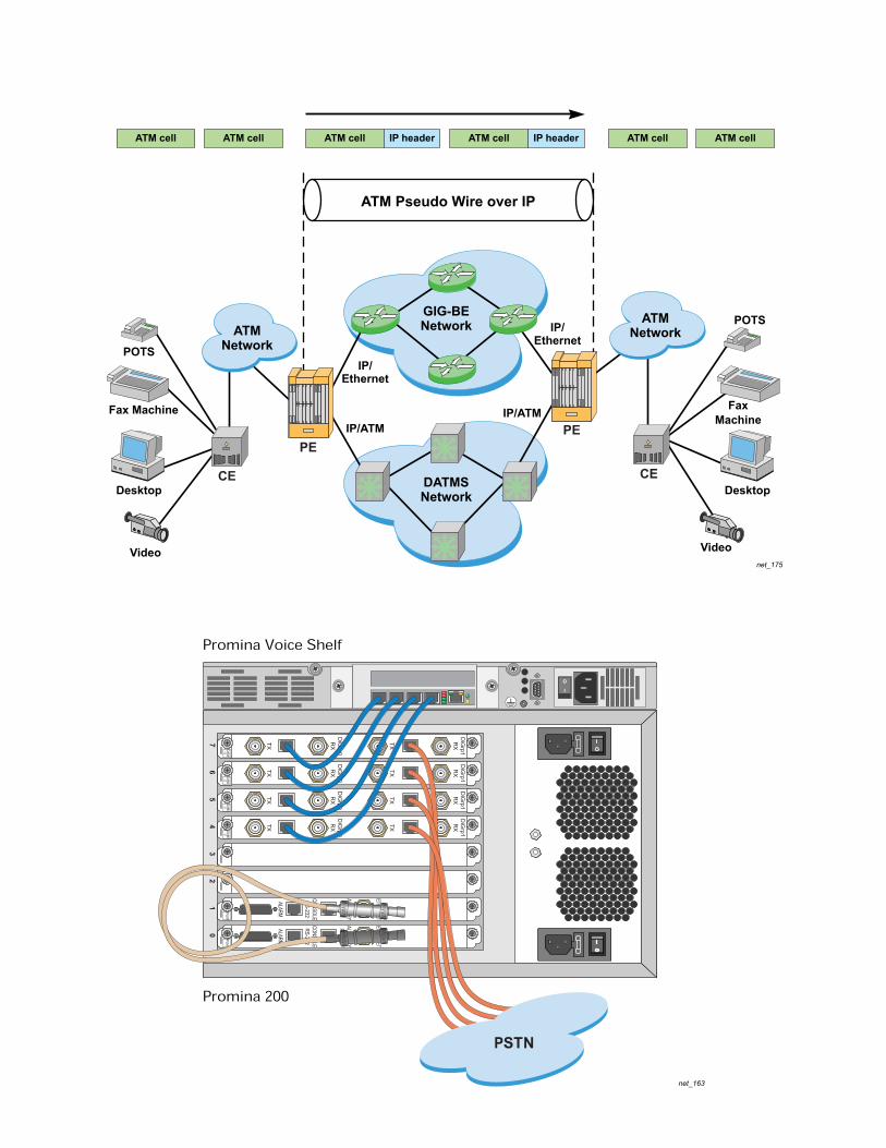
net_163
net_175
POTSIP/
Ethernet
IP/Ethernet
IP/ATMIP/ATM
Video
Fax Machine
Desktop DATMSNetwork
ATMNetwork
GIG-BENetwork
ATM Pseudo Wire over IP
POTS
Video
FaxMachine
Desktop
ATMNetwork
ATM cellATM cellATM cell ATM cellATM cellIP header ATM cell IP header
CE
PEPE
CE
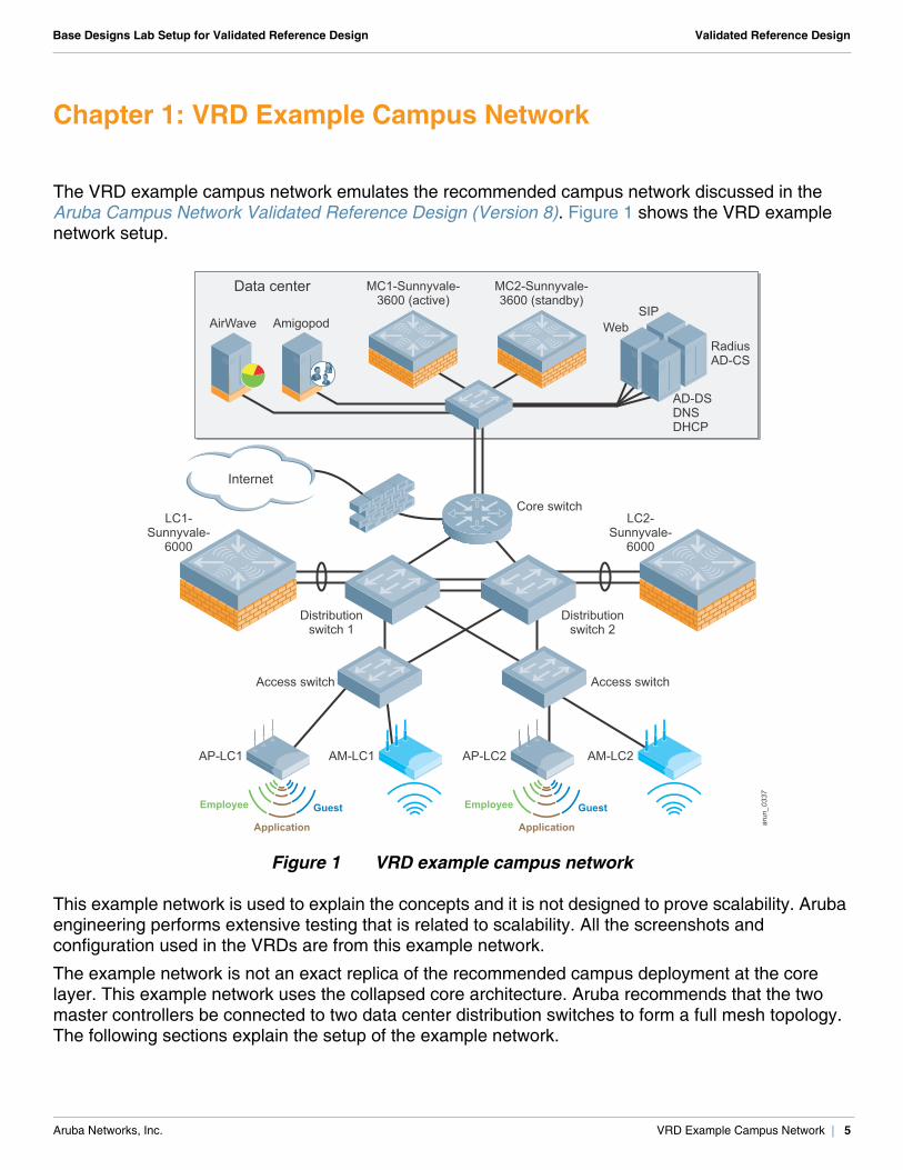
Aruba Networks, Inc. VRD Example Campus Network | 5
Base Designs Lab Setup for Validated Reference Design Validated Reference Design
Chapter 1: VRD Example Campus Network
The VRD example campus network emulates the recommended campus network discussed in the Aruba Campus Network Validated Reference Design (Version 8). Figure 1 shows the VRD example network setup.
Figure 1 VRD example campus network
This example network is used to explain the concepts and it is not designed to prove scalability. Aruba engineering performs extensive testing that is related to scalability. All the screenshots and configuration used in the VRDs are from this example network.
The example network is not an exact replica of the recommended campus deployment at the core layer. This example network uses the collapsed core architecture. Aruba recommends that the two master controllers be connected to two data center distribution switches to form a full mesh topology. The following sections explain the setup of the example network.
arun_0337
AM-LC1AP-LC1 AM-LC2AP-LC2
GuestEmployee
Application
GuestEmployee
Application
Internet
Data center MC1-Sunnyvale-3600 (active)
MC2-Sunnyvale-3600 (standby)
LC1-Sunnyvale-
6000
LC2-Sunnyvale-
6000
WebSIP
RadiusAD-CS
AD-DSDNSDHCP
Core switch
Distributionswitch 2
Access switchAccess switch
Distributionswitch 1
AirWave Amigopod
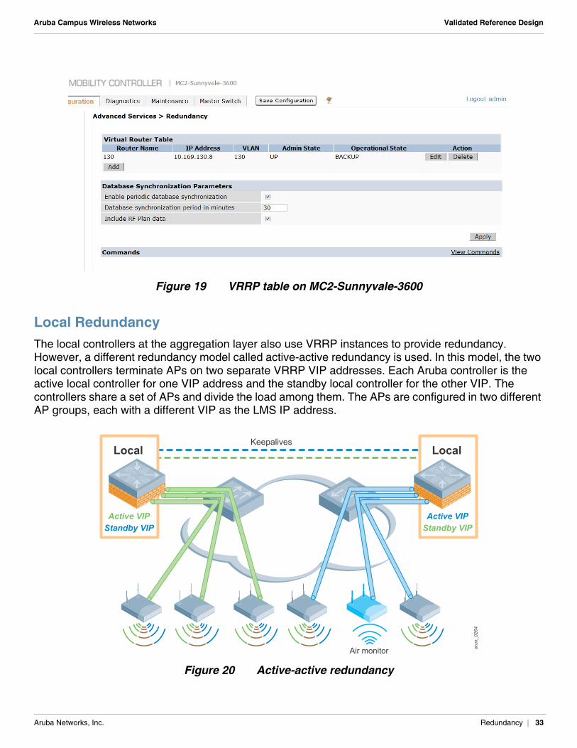
Aruba Networks, Inc. Redundancy | 33
Aruba Campus Wireless Networks Validated Reference Design
Figure 19 VRRP table on MC2-Sunnyvale-3600
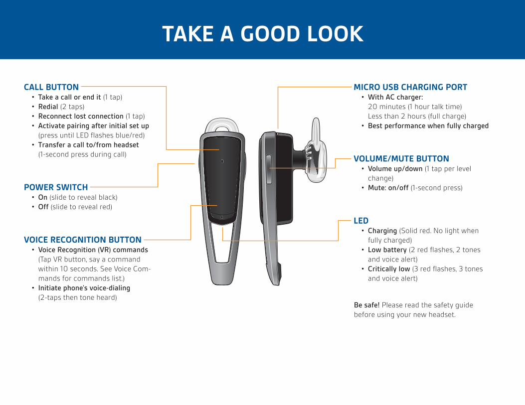
Local RedundancyThe local controllers at the aggregation layer also use VRRP instances to provide redundancy. However, a different redundancy model called active-active redundancy is used. In this model, the two local controllers terminate APs on two separate VRRP VIP addresses. Each Aruba controller is the active local controller for one VIP address and the standby local controller for the other VIP. The controllers share a set of APs and divide the load among them. The APs are configured in two different AP groups, each with a different VIP as the LMS IP address.
Figure 20 Active-active redundancy
arun_044
arun_0264
Air monitor
Keepalives
Active VIPStandby VIP
Local
Active VIPStandby VIP
Local