Embed Size (px)
Citation preview
1 ©2015 Comba Telecom. All Rights Reserved
MEETING THE
DATA DEMAND TIDAL WAVE:
UPGRADE OF INDOOR DAS FOR LTE
May 2015
A Comba Telecom White Paper
2 ©2015 Comba Telecom. All Rights Reserved
TABLE OF CONTENTS EXECUTIVE SUMMARY .................................................................................................... 3
EVOLVING MARKET DEMAND TOWARDS LTE ..................................................................... 4
CONSIDERATIONS FOR INDOOR LTE DEPLOYMENT ............................................................... 4
CASE STUDY ................................................................................................................. 5
Phase I .......................................................................................................................................... 6
Phase II ......................................................................................................................................... 7
Phase III ........................................................................................................................................ 8
Summary of Results ..................................................................................................................... 9
CONCLUSION .............................................................................................................. 10
ABOUT COMBA TELECOM ............................................................................................. 11

3 ©2015 Comba Telecom. All Rights Reserved
EXECUTIVE SUMMARY
Consumers have become heavily dependent on their mobile devices and
expect uninterrupted ubiquitous coverage and fast data performance.
Network operators are encountering an overwhelming amount of data traffic
that is forcing them to embrace efficient data-centric technologies like LTE.
A large volume of mobile data is being consumed indoors; such as residential
buildings, offices and commercial spaces. In-building systems (IBS) were
typically deployed in sites with high voice traffic or serving important
customers/corporate accounts, due to the additional CAPEX investments.
Indoor coverage in most other buildings is incidental, served by macro outdoor
base stations nearby. Coverage tended to be limited, due to the building
penetration losses.
With rapid urbanization and building densification, outdoor cell sites are
increasingly inadequate to meet indoor consumption demands and
expectations. Existing distributed antenna system (DAS) built for voice services
on GSM and even 3G is not capable of delivering the customer’s expected data
performance with a direct upgrade of base station equipment.
To retain and attract customers, operators need to channel investments into
indoor systems beyond outdoor rollout for 3G/4G. However, with limited
CAPEX, the low hanging fruit is to upgrade important buildings with existing
DAS systems to ensure they meet the required data quality of service (QoS).
In the case study, we see that re-using DAS infrastructure designed for voice
cannot meet the data requirements for LTE or even HSPA. The antenna must
be densified by approximately 1.5 times to achieve the desired LTE high data
rates.
This paper discusses the growing market demand for data centric technologies
and concerns regarding its efficient indoor deployment. It also presents a case
study to quantify the CAPEX investment versus performance improvement for
evolving from voice centric IBS to support LTE/HSPA.
4 ©2015 Comba Telecom. All Rights Reserved
EVOLVING MARKET DEMAND TOWARDS LTE
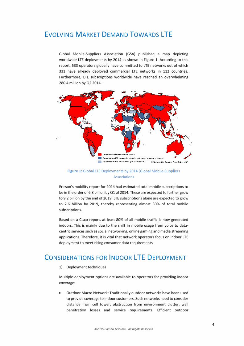
Global Mobile-Suppliers Association (GSA) published a map depicting
worldwide LTE deployments by 2014 as shown in Figure 1. According to this
report, 533 operators globally have committed to LTE networks out of which
331 have already deployed commercial LTE networks in 112 countries.
Furthermore, LTE subscriptions worldwide have reached an overwhelming
280.4 million by Q2 2014.
Figure 1: Global LTE Deployments by 2014 (Global Mobile-Suppliers
Association)
Ericson’s mobility report for 2014 had estimated total mobile subscriptions to
be in the order of 6.8 billion by Q1 of 2014. These are expected to further grow
to 9.2 billion by the end of 2019. LTE subscriptions alone are expected to grow
to 2.6 billion by 2019, thereby representing almost 30% of total mobile
subscriptions.
Based on a Cisco report, at least 80% of all mobile traffic is now generated
indoors. This is mainly due to the shift in mobile usage from voice to data-
centric services such as social networking, online gaming and media streaming
applications. Therefore, it is vital that network operators focus on indoor LTE
deployment to meet rising consumer data requirements.
CONSIDERATIONS FOR INDOOR LTE DEPLOYMENT 1) Deployment techniques
Multiple deployment options are available to operators for providing indoor
coverage:
Outdoor Macro Network: Traditionally outdoor networks have been used
to provide coverage to indoor customers. Such networks need to consider
distance from cell tower, obstruction from environment clutter, wall
penetration losses and service requirements. Efficient outdoor
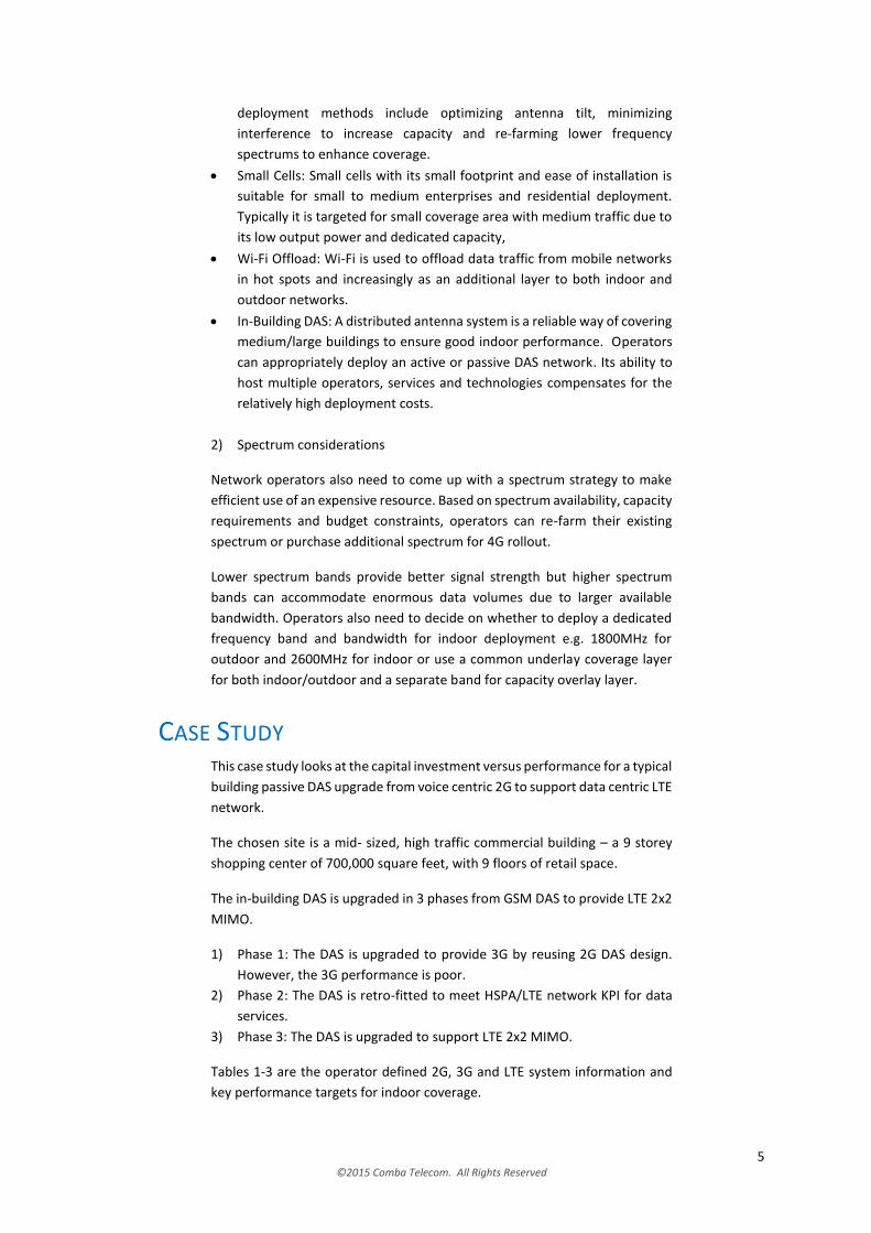
5 ©2015 Comba Telecom. All Rights Reserved
deployment methods include optimizing antenna tilt, minimizing
interference to increase capacity and re-farming lower frequency
spectrums to enhance coverage.
Small Cells: Small cells with its small footprint and ease of installation is
suitable for small to medium enterprises and residential deployment.
Typically it is targeted for small coverage area with medium traffic due to
its low output power and dedicated capacity,
Wi-Fi Offload: Wi-Fi is used to offload data traffic from mobile networks
in hot spots and increasingly as an additional layer to both indoor and
outdoor networks.
In-Building DAS: A distributed antenna system is a reliable way of covering
medium/large buildings to ensure good indoor performance. Operators
can appropriately deploy an active or passive DAS network. Its ability to
host multiple operators, services and technologies compensates for the
relatively high deployment costs.
2) Spectrum considerations
Network operators also need to come up with a spectrum strategy to make
efficient use of an expensive resource. Based on spectrum availability, capacity
requirements and budget constraints, operators can re-farm their existing
spectrum or purchase additional spectrum for 4G rollout.
Lower spectrum bands provide better signal strength but higher spectrum
bands can accommodate enormous data volumes due to larger available
bandwidth. Operators also need to decide on whether to deploy a dedicated
frequency band and bandwidth for indoor deployment e.g. 1800MHz for
outdoor and 2600MHz for indoor or use a common underlay coverage layer
for both indoor/outdoor and a separate band for capacity overlay layer.
CASE STUDY This case study looks at the capital investment versus performance for a typical
building passive DAS upgrade from voice centric 2G to support data centric LTE
network.
The chosen site is a mid- sized, high traffic commercial building – a 9 storey
shopping center of 700,000 square feet, with 9 floors of retail space.
The in-building DAS is upgraded in 3 phases from GSM DAS to provide LTE 2x2
MIMO.
1) Phase 1: The DAS is upgraded to provide 3G by reusing 2G DAS design.
However, the 3G performance is poor.
2) Phase 2: The DAS is retro-fitted to meet HSPA/LTE network KPI for data
services.
3) Phase 3: The DAS is upgraded to support LTE 2x2 MIMO.
Tables 1-3 are the operator defined 2G, 3G and LTE system information and
key performance targets for indoor coverage.
6 ©2015 Comba Telecom. All Rights Reserved
Table 1: KPI for 2G
Technical Specification Criteria
Frequency 900MHz, 1800MHz
Signal Transmit Power at BTS output 39 dBm
RxLev >= -80 dBm @ 99% coverage area
Table 2: KPI for 3G
Technical Specification Criteria
Frequency band 2100MHz
CPICH Transmit Power at Node B output 30 dBm
CPICH RSCP >= -90 dBm @ 99% coverage area
CPICH Ec/No >= -10 dB @ 99% coverage area
Average DL FTP Throughput (HSDPA) Average up to 4 Mbps walktest
Table 3: KPI for LTE
Technical Specification Criteria
Frequency Band/Bandwidth 1800MHz (10MHz)
LTE Pilot Transmit Power at eNodeB output
15 dBm
LTE RSRP >= -92 dBm @ 99% coverage area
LTE RSRQ >= -12 dB @99% coverage area
Average Downlink Throughput > 24 Mbps (2x2 MIMO)
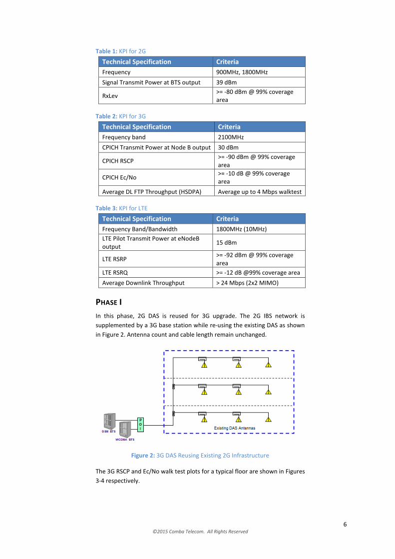
PHASE I
In this phase, 2G DAS is reused for 3G upgrade. The 2G IBS network is
supplemented by a 3G base station while re-using the existing DAS as shown
in Figure 2. Antenna count and cable length remain unchanged.
Figure 2: 3G DAS Reusing Existing 2G Infrastructure
The 3G RSCP and Ec/No walk test plots for a typical floor are shown in Figures
3-4 respectively.
7 ©2015 Comba Telecom. All Rights Reserved
Figure 3: RSCP Walk test Plot for 3G IBS
Figure 4: Ec/No Walk test Plot for 3G IBS
The RSCP plot shows the 3G signal strength greater than -90dBm for only
72.7%. Similarly, Ec/No plot indicates that 3G signal quality was better than -
10dB for 38.6% of the same floor.
From these plots, we observe that a direct re-use of 2G DAS is incapable of
meeting the required 3G KPI targets. The DAS design needs to be enhanced.
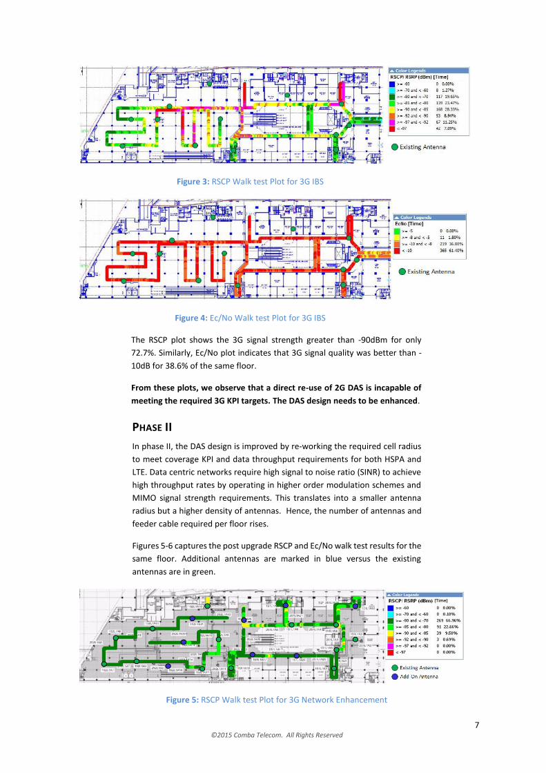
PHASE II
In phase II, the DAS design is improved by re-working the required cell radius
to meet coverage KPI and data throughput requirements for both HSPA and
LTE. Data centric networks require high signal to noise ratio (SINR) to achieve
high throughput rates by operating in higher order modulation schemes and
MIMO signal strength requirements. This translates into a smaller antenna
radius but a higher density of antennas. Hence, the number of antennas and
feeder cable required per floor rises.
Figures 5-6 captures the post upgrade RSCP and Ec/No walk test results for the
same floor. Additional antennas are marked in blue versus the existing
antennas are in green.
Figure 5: RSCP Walk test Plot for 3G Network Enhancement
8 ©2015 Comba Telecom. All Rights Reserved
Figure 6: Ec/No Walk test Plot for 3G Network Enhancement
The plots indicates RSCP greater than -90dBm and Ec/No better than -10dB for
more than 99% of the coverage area. Also, the average HSDPA downlink
throughput measured on site was found to be 9.2Mbps.
From these results we can see that the 3G KPI is fulfilled after the re-design
and antenna densification.
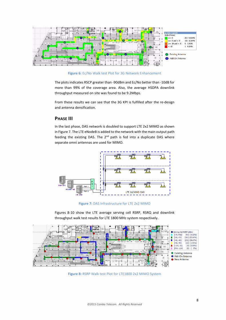
PHASE III
In the last phase, DAS network is doubled to support LTE 2x2 MIMO as shown
in Figure 7. The LTE eNodeB is added to the network with the main output path
feeding the existing DAS. The 2nd path is fed into a duplicate DAS where
separate omni antennas are used for MIMO.
Figure 7: DAS Infrastructure for LTE 2x2 MIMO
Figures 8-10 show the LTE average serving cell RSRP, RSRQ and downlink
throughput walk test results for LTE 1800 MHz system respectively.
Figure 8: RSRP Walk test Plot for LTE1800 2x2 MIMO System

9 ©2015 Comba Telecom. All Rights Reserved
Figure 9: RSRQ Walk test Plot for LTE1800 2x2 MIMO System
Figure 10: Cell Downlink Throughput Walk test Plot for LTE1800 2x2 MIMO System
The RSRP plot shows signal strength more than -92dBm and RSRQ better than
-12dB for more than 99% of coverage area. The cell downlink throughput
achieved an average of 33.9Mbps for 10MHz of bandwidth.
The LTE KPIs are satisfied after upgrading the DAS to be MIMO 2x2 ready.
SUMMARY OF RESULTS
Table 4 summarizes the improvement in measured KPI per phase of the DAS
upgrade.
Table 4: IBS Performance at each phase of DAS upgrade
Phase I Phase II Phase III
3G KPI
RSCP Target RSCP >= -90 dBm @ 99% coverage area
Achieved @ 72.7% >@ 99% >@ 99%
EcNo Target Ec/No >= -10 dB @ 99% coverage area
Achieved @ 38.6% >@ 99% >@ 99%
Throughput Target Avg. DL FTP throughput (HSPA) >= 4 Mbps
Achieved 9.2 Mbps* 9.2 Mbps*
LTE KPI
RSRP Target
RSRP >= -92 dBm @ 99%
Achieved >@99%
RSRQ Target RSRQ >= -12 dB @ 99%
Achieved > @99%
Throughput Target Avg. DL FTP Throughput
>= 24 Mbps
Achieved 33.9 Mbps*
* Achieved throughput rate varies with network traffic
10 ©2015 Comba Telecom. All Rights Reserved
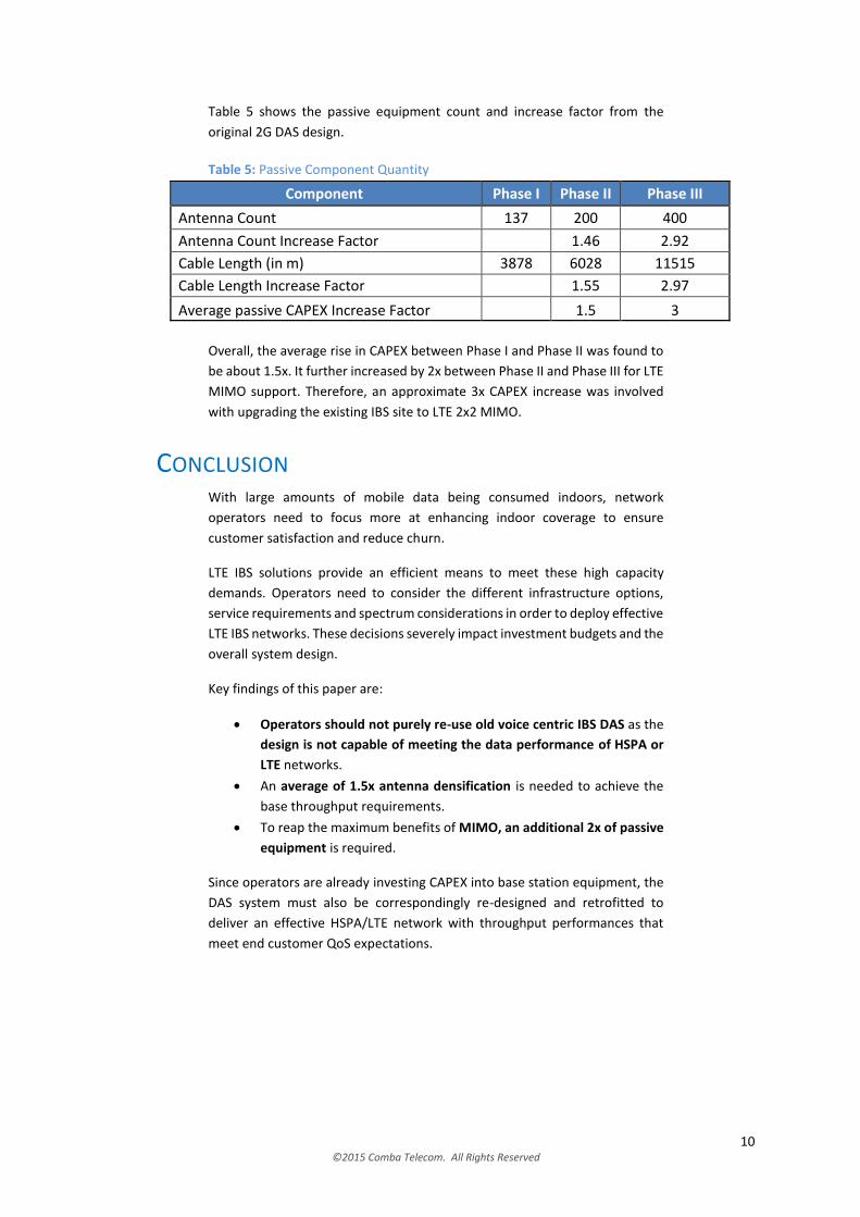
Table 5 shows the passive equipment count and increase factor from the
original 2G DAS design.
Table 5: Passive Component Quantity
Component Phase I Phase II Phase III
Antenna Count 137 200 400
Antenna Count Increase Factor 1.46 2.92
Cable Length (in m) 3878 6028 11515
Cable Length Increase Factor 1.55 2.97
Average passive CAPEX Increase Factor 1.5 3
Overall, the average rise in CAPEX between Phase I and Phase II was found to
be about 1.5x. It further increased by 2x between Phase II and Phase III for LTE
MIMO support. Therefore, an approximate 3x CAPEX increase was involved
with upgrading the existing IBS site to LTE 2x2 MIMO.
CONCLUSION With large amounts of mobile data being consumed indoors, network
operators need to focus more at enhancing indoor coverage to ensure
customer satisfaction and reduce churn.
LTE IBS solutions provide an efficient means to meet these high capacity
demands. Operators need to consider the different infrastructure options,
service requirements and spectrum considerations in order to deploy effective
LTE IBS networks. These decisions severely impact investment budgets and the
overall system design.
Key findings of this paper are:
Operators should not purely re-use old voice centric IBS DAS as the
design is not capable of meeting the data performance of HSPA or
LTE networks.
An average of 1.5x antenna densification is needed to achieve the
base throughput requirements.
To reap the maximum benefits of MIMO, an additional 2x of passive
equipment is required.
Since operators are already investing CAPEX into base station equipment, the
DAS system must also be correspondingly re-designed and retrofitted to
deliver an effective HSPA/LTE network with throughput performances that
meet end customer QoS expectations.
11 ©2015 Comba Telecom. All Rights Reserved
ABOUT COMBA TELECOM Comba Telecom is a leading supplier of infrastructure and wireless
enhancement solutions to mobile operators and enterprises to enhance and
extend their wireless communications networks. With over 50,000 system
deployments around the world including turnkey in-building systems,
urban/rural wireless systems, and transport wireless networks, Comba
Telecom’s end-to-end network solutions include consultation, network design,
optimization and commissioning.
Comba Telecom’s product portfolio includes DAS, small cells, tower mounted
systems, antennas, subsystems, passive accessories, Wi-Fi systems and digital
microwave links.
Listed on the Hong Kong Stock Exchange, Comba Telecom is headquartered in
Hong Kong and has operations throughout the Americas, Europe, Middle East,
Africa and Asia Pacific. To learn more, visit www.comba-telecom.com and
follow Comba Telecom on LinkedIn for regular updates.
www.comba-telecom.com [email protected]
© 2015 Comba Telecom. All rights reserved. Comba Telecom reserves the right to change, modify, transfer, or otherwise revise this
publication and the product specifications without notice. While Comba Telecom uses commercially reasonable efforts to ensure the
accuracy of the specifications contained in this document, Comba Telecom and its affiliated companies will assume no responsibility for any
errors or omissions. Nothing in this publication forms any part of any contract.