Embed Size (px)
Citation preview
Basic Laws of Optics
•Snell’s Law
•Law of Reflection
•Diffraction
Ray Theory
• A number of optic phenomena are adequately explained by considering that optical energy in a wave follows narrow paths called rays.
– Rays are really geometrical path
• These rays are used to describe optical effect geometrically
– Ray theory is called geometrical optics

Rays obey a few simple rules
1. In a vacuum, rays travel at the velocity c=3108 m/s.
• In any other medium, ray travel at a slower speed v = c/n
2. Ray travel in straight paths unless deflected by some change in the medium.
3. Reflection Law
4. Snell’s Law
Reflection Law
• At a plane boundary between two media, a ray is reflected at an angle equal to the angle of incidence
• The angles are measured with respect to the boundary normal,
qr = qi
q i is the angle of incidence
qr is the angle of reflection
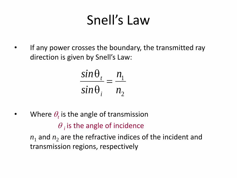
Snell’s Law
• If any power crosses the boundary, the transmitted ray direction is given by Snell’s Law:
• Where qt is the angle of transmission
q i is the angle of incidence
n1 and n2 are the refractive indices of the incident and transmission regions, respectively
2
1
n
n
sin
sin
i
t q
q

Refraction and reflection
q i
q t
q r

Total internal reflection (TIR)
• For n1>n2, the transmitted angle is greater than the incidence angle.
• When the refraction angle, q t =90, the incidence angle is called critical angle q i= q c, in which
sinqc = n2/n1
– When the incidence angle q i >qc, there is no transmitted wave but only a reflected wave.
– It is called total internal reflection

n2
qi
n1 > n
2
qi
Incident
light
qt
Transmitted
(refracted) light
Reflected
light
kt
qi>q
cq
c
TIR
qc
Evanescent wave
ki
kr
(a) (b) (c)
Light wave travelling in a more dense medium strikes a less dense medium. Depending onthe incidence angle with respect to qc, which is determined by the ratio of the refractive
indices, the wave may be transmitted (refracted) or reflected. (a) qi < qc (b) qi = qc (c) qi
> qc and total internal reflection (TIR).
© 1999 S.O. Kasap, Optoelectronics (Prentice Hall)
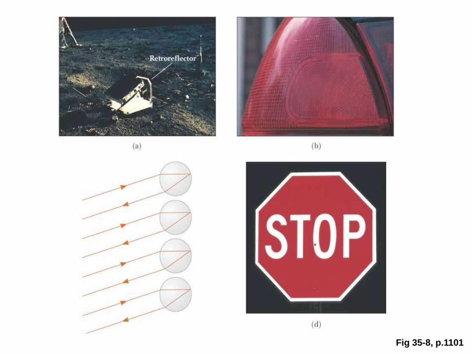
Fig 35-8, p.1101
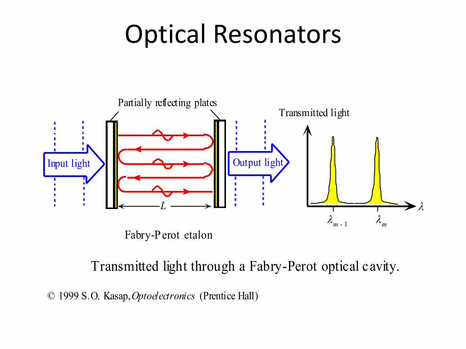
Optical Resonators
• Optical Resonator is the optical counterpart of the electrical resonator, storing energy or filtering light only at certain frequency (wavelength).
• When two flat mirrors M1 and M2 aligned to be parallel with free space between them, light wave reflections between the mirror lead to constructive and destructive interference in the cavity.
• The waves traveling to left interfere with the waves traveling to right. The result is a series of stationary and standing EM waves.
Optical Resonators
A
B
L
M1
M2 m = 1
m = 2
m = 8
Relative intensity
u
dum
um
um + 1
um - 1
(a) (b) (c)
R~ 0.4
R~ 0.81 uf
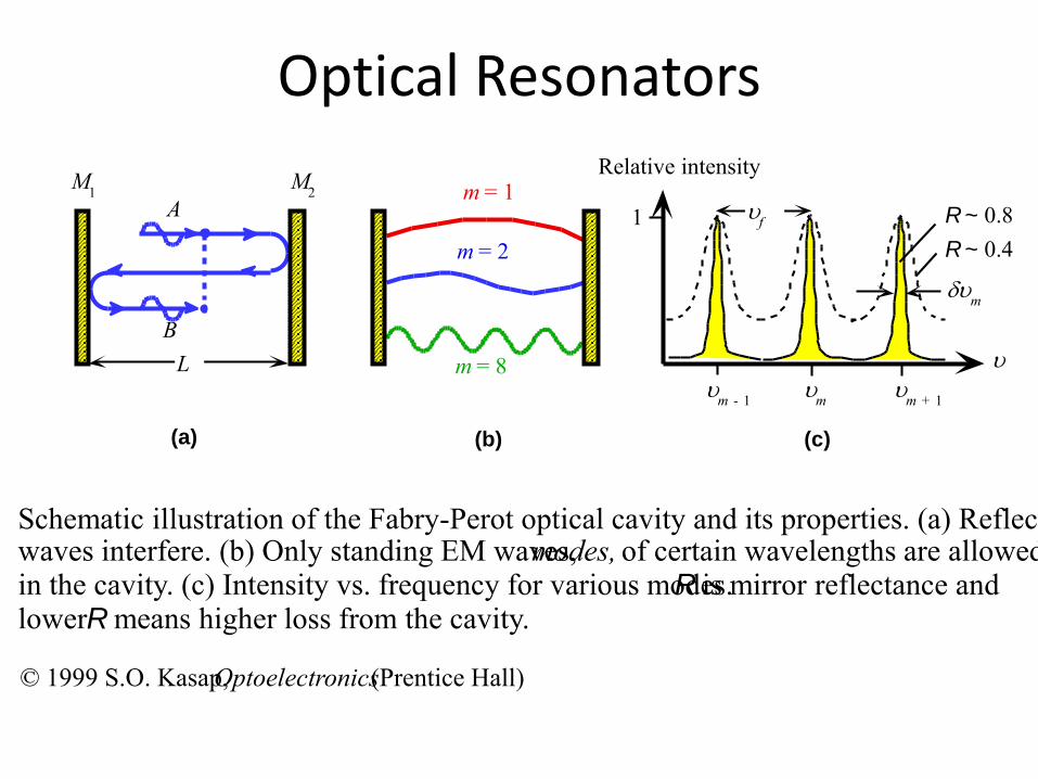
Schematic illustration of the Fabry-Perot optical cavity and its properties. (a) Reflectedwaves interfere. (b) Only standing EM waves, modes, of certain wavelengths are allowedin the cavity. (c) Intensity vs. frequency for various modes. R is mirror reflectance andlower R means higher loss from the cavity.
© 1999 S.O. Kasap, Optoelectronics (Prentice Hall)
L
m
m - 1
Fabry-P erot etalon
Partially reflecting plates
Output lightInput light
Transmitted light
Transmitted light through a Fabry-Perot optical cavity.
© 1999 S.O. Kasap, Optoelectronics (Prentice Hall)
Optical Resonators

Optical Resonators
( )2
m L
( ) ;2 2
m f f
c cm m
L Lu u u
Where m defines the cavity mode.
υf is the fundamental mode, and also frequency separation of two neighboring modes. It also know as free spectral range (FSR)
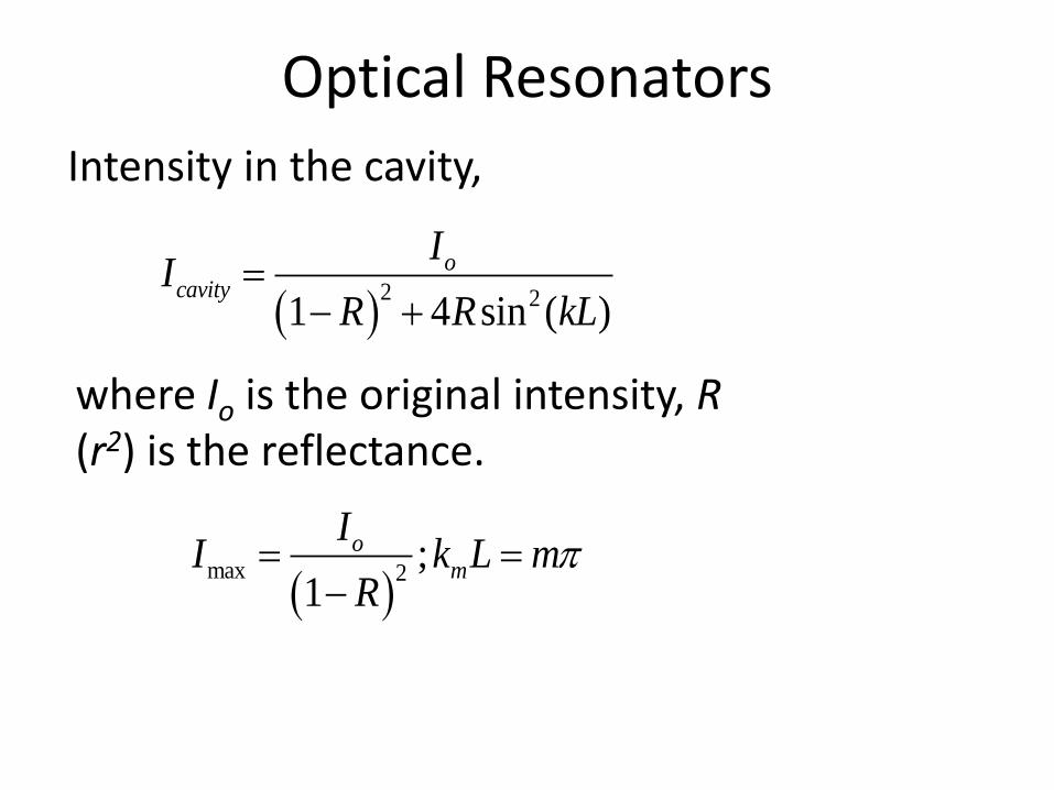
Optical Resonators
2 21 4 sin ( )
ocavity
II
R R kL
Intensity in the cavity,
where Io is the original intensity, R(r2) is the reflectance.
max 2
;1
om
II k L m
R

Optical Resonators
The spectral width δυm of Fabry-Perot etalon is the full width at half maximum (FWHM) of an individual mode intensity.
1
2
;1
f
m
RF
F R
u du
In which F is known as Finesse of the resonator, which increases as losses decrease (R increases). Large Finesse lead to sharper mode peaks.
Wave optics
• Geometrical optics (ray theory) correctly predict the gross result but does not agree with the fine details of the observation.
• Actual light sources often produce non-uniform beams. – The intensities vary across the transverse plane
– A particularly important transverse pattern is the Gaussian distribution.

Diffraction
• Diffraction is the deviation from the predictions of geometrical optics.
• For example, a collimated light beam passing through a circular aperture.
– The passing beam is found to be divergent and to exhibit an intensity pattern that has bright & dark rings called Airy Ring.
– The intensity pattern is called diffraction pattern.

Light intens ity pattern
Incident light wave
Diffracted beam
Circular aperture
A light beam incident on a small circular aperture becomes diffracted and its lightintensity pattern after passing through the aperture is a diffraction pattern with circularbright rings (called Airy rings). If the screen is far away from the aperture, this would be aFraunhofer diffraction pattern.
© 1999 S.O. Kasap, Optoelectronics (Prentice Hall)
Principle of diffraction
• Diffraction can be understood in term of the interference of multiple waves emanating from the obstruction.
• Every unobstructed point of a wavefront, serves as a source of spherical waves.– The amplitude of the optical field at any point
beyond is the superposition of all these wavelets. (considering their amplitudes and relative phases)

Incident plane wave
New
wavefront
A secondary
wave source
(a) (b)
Another new
wavefront (diffracted)
zq
(a) Huygens-Fresnel principles states that each point in the aperture becomes a source ofsecondary waves (spherical waves). The spherical wavefronts are separated by . The newwavefront is the envelope of the all these spherical wavefronts. (b) Another possiblewavefront occurs at an angle q to the z-direction which is a diffracted wave.
© 1999 S.O. Kasap, Optoelectronics (Prentice Hall)

q
A
ysinq
y
Y
q
q
dy
zdy
ScreenIncident
light wave
q
R = Large
q
c
b
Light intensity
a
y
y
z
(a) (b)
(a) The aperture is divided into N number of point sources each occupying dy withamplitude dy. (b) The intensity distribution in the received light at the screen far awayfrom the aperture: the diffraction pattern
Incident
light wave
© 1999 S.O. Kasap, Optoelectronics (Prentice Hall)