Embed Size (px)
Citation preview
Chapter 7 – Design and Implementation
Chapter 7 Design and Implementation 130/10/2014
Topics covered
Object-oriented design using the UML
Design patterns
Implementation issues
Open source development
Chapter 7 Design and Implementation 230/10/2014
Design and implementation
Software design and implementation is the stage in the
software engineering process at which an executable
software system is developed.
Software design and implementation activities are
invariably inter-leaved.
Software design is a creative activity in which you identify
software components and their relationships, based on a
customer’s requirements.
Implementation is the process of realizing the design as a
program.
Chapter 7 Design and Implementation 330/10/2014
Build or buy
In a wide range of domains, it is now possible to buy off-
the-shelf systems (COTS) that can be adapted and
tailored to the users’ requirements.
For example, if you want to implement a medical records system,
you can buy a package that is already used in hospitals. It can
be cheaper and faster to use this approach rather than
developing a system in a conventional programming language.
When you develop an application in this way, the design
process becomes concerned with how to use the
configuration features of that system to deliver the
system requirements.
Chapter 7 Design and Implementation 430/10/2014
Object-oriented design using the UML
Chapter 7 Design and Implementation 530/10/2014
An object-oriented design process
Structured object-oriented design processes involve developing a number of different system models.
They require a lot of effort for development and maintenance of these models and, for small systems, this may not be cost-effective.
However, for large systems developed by different groups design models are an important communication mechanism.
Chapter 7 Design and Implementation 630/10/2014
Process stages
There are a variety of different object-oriented design
processes that depend on the organization using the
process.
Common activities in these processes include:
Define the context and modes of use of the system;
Design the system architecture;
Identify the principal system objects;
Develop design models;
Specify object interfaces.
Process illustrated here using a design for a wilderness
weather station.
Chapter 7 Design and Implementation 730/10/2014
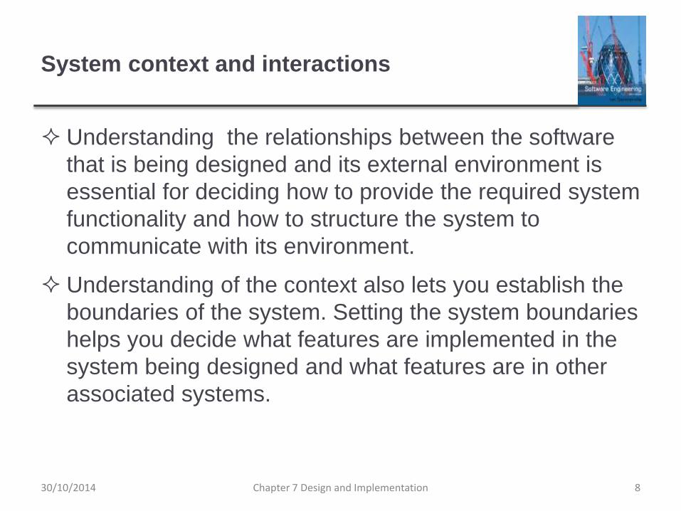
System context and interactions
Understanding the relationships between the software
that is being designed and its external environment is
essential for deciding how to provide the required system
functionality and how to structure the system to
communicate with its environment.
Understanding of the context also lets you establish the
boundaries of the system. Setting the system boundaries
helps you decide what features are implemented in the
system being designed and what features are in other
associated systems.
Chapter 7 Design and Implementation 830/10/2014
Context and interaction models
A system context model is a structural model that
demonstrates the other systems in the environment of
the system being developed.
An interaction model is a dynamic model that shows how
the system interacts with its environment as it is used.
Chapter 7 Design and Implementation 930/10/2014
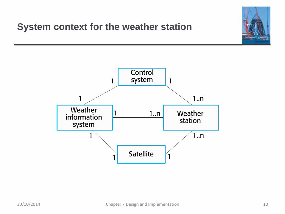
System context for the weather station
Chapter 7 Design and Implementation 1030/10/2014
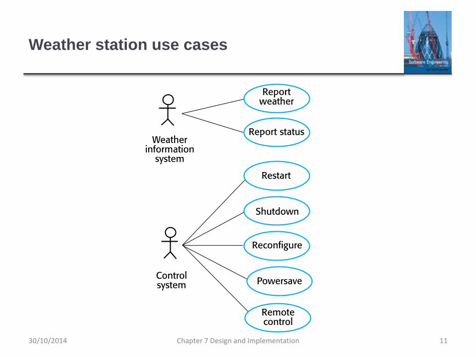
Weather station use cases
Chapter 7 Design and Implementation 1130/10/2014
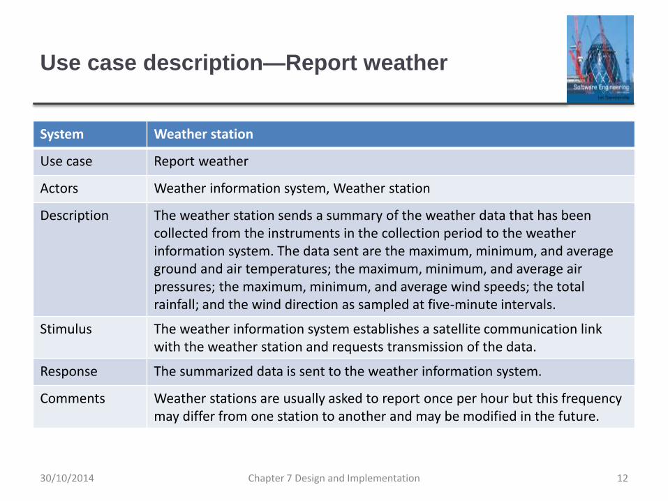
Use case description—Report weather
System Weather station
Use case Report weather
Actors Weather information system, Weather station
Description The weather station sends a summary of the weather data that has been collected from the instruments in the collection period to the weather information system. The data sent are the maximum, minimum, and average ground and air temperatures; the maximum, minimum, and average air pressures; the maximum, minimum, and average wind speeds; the total rainfall; and the wind direction as sampled at five-minute intervals.
Stimulus The weather information system establishes a satellite communication link with the weather station and requests transmission of the data.
Response The summarized data is sent to the weather information system.
Comments Weather stations are usually asked to report once per hour but this frequency may differ from one station to another and may be modified in the future.
Chapter 7 Design and Implementation 1230/10/2014
Architectural design
Once interactions between the system and its
environment have been understood, you use this
information for designing the system architecture.
You identify the major components that make up the
system and their interactions, and then may organize the
components using an architectural pattern such as a
layered or client-server model.
The weather station is composed of independent
subsystems that communicate by broadcasting
messages on a common infrastructure.
Chapter 7 Design and Implementation 1330/10/2014
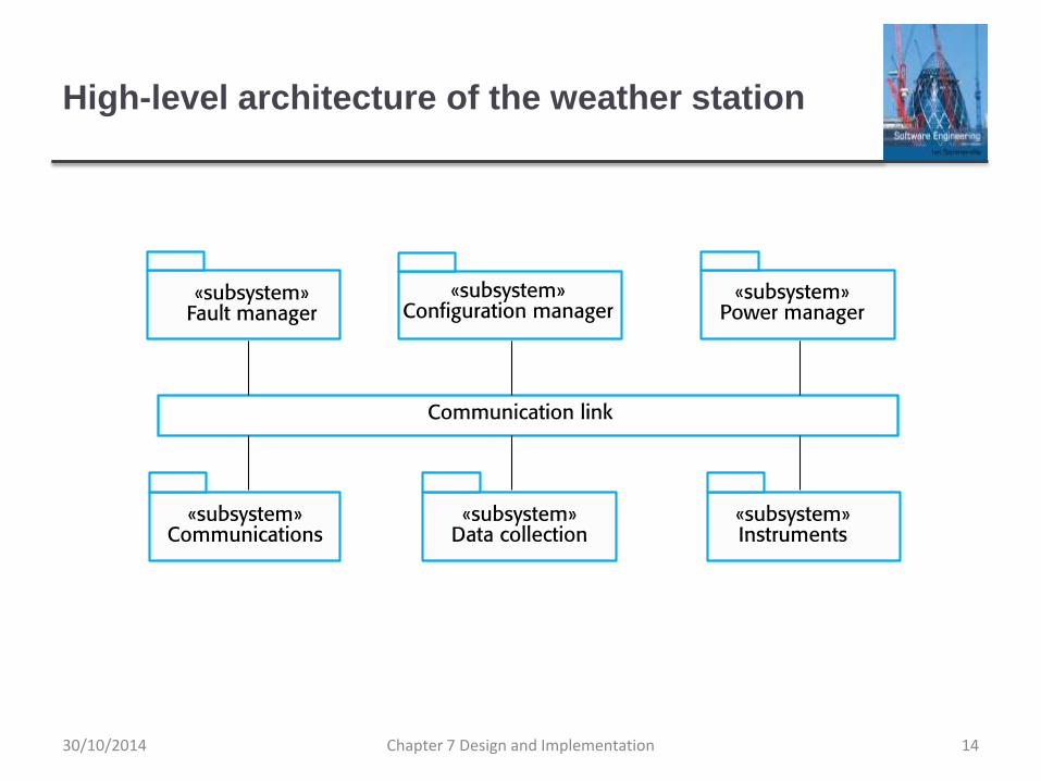
High-level architecture of the weather station
Chapter 7 Design and Implementation 1430/10/2014
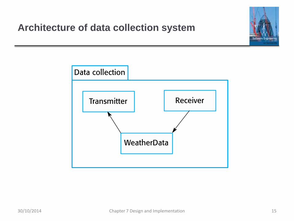
Architecture of data collection system
Chapter 7 Design and Implementation 1530/10/2014
Object class identification
Identifying object classes is often a difficult part of object
oriented design.
There is no 'magic formula' for object identification. It
relies on the skill, experience
and domain knowledge of system designers.
Object identification is an iterative process. You are
unlikely to get it right first time.
Chapter 7 Design and Implementation 1630/10/2014
Approaches to identification
Use a grammatical approach based on a natural
language description of the system.
Base the identification on tangible things in the
application domain.
Use a behavioural approach and identify objects based
on what participates in what behaviour.
Use a scenario-based analysis. The objects, attributes
and methods in each scenario are identified.
Chapter 7 Design and Implementation 1730/10/2014
Weather station object classes
Object class identification in the weather station system
may be based on the tangible hardware and data in the
system:
Ground thermometer, Anemometer, Barometer
• Application domain objects that are ‘hardware’ objects related to the
instruments in the system.
Weather station
• The basic interface of the weather station to its environment. It
therefore reflects the interactions identified in the use-case model.
Weather data
• Encapsulates the summarized data from the instruments.
Chapter 7 Design and Implementation 1830/10/2014
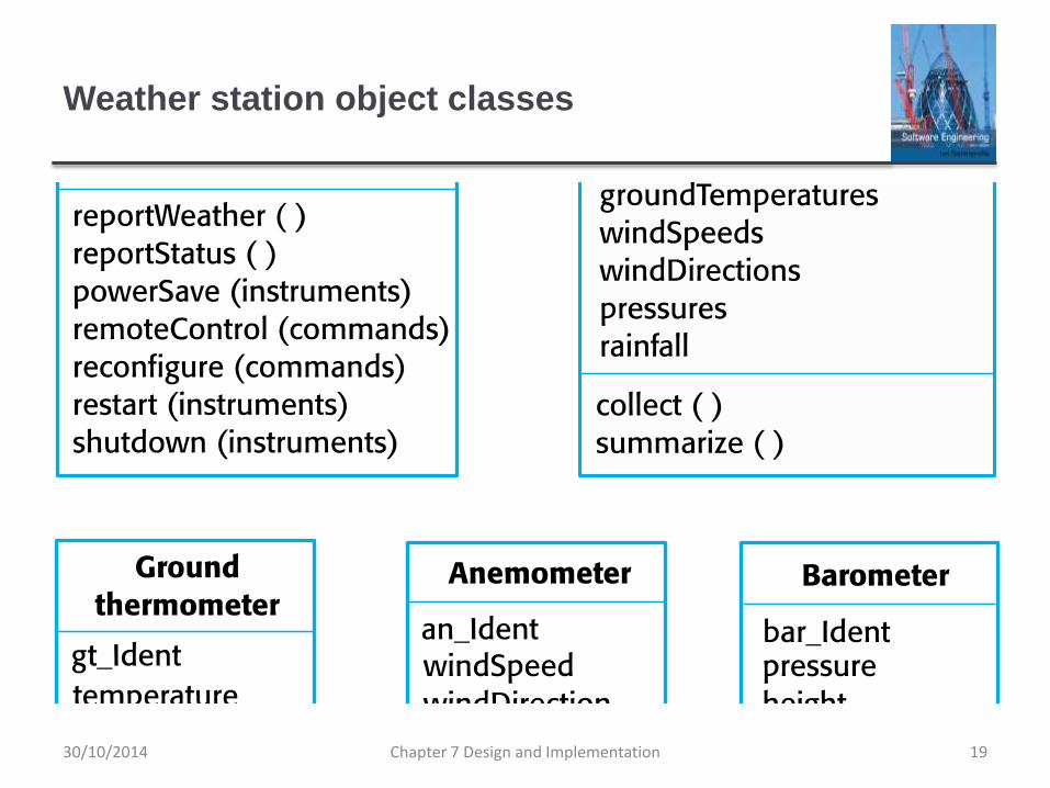
Weather station object classes
Chapter 7 Design and Implementation 1930/10/2014
Design models
Design models show the objects and object classes and
relationships between these entities.
There are two kinds of design model:
Structural models describe the static structure of the system in
terms of object classes and relationships.
Dynamic models describe the dynamic interactions between
objects.
Chapter 7 Design and Implementation 2030/10/2014
Examples of design models
Subsystem models that show logical groupings of
objects into coherent subsystems.
Sequence models that show the sequence of object
interactions.
State machine models that show how individual objects
change their state in response to events.
Other models include use-case models, aggregation
models, generalisation models, etc.
Chapter 7 Design and Implementation 2130/10/2014
Subsystem models
Shows how the design is organised into logically related
groups of objects.
In the UML, these are shown using packages - an
encapsulation construct. This is a logical model. The
actual organisation of objects in the system may be
different.
Chapter 7 Design and Implementation 2230/10/2014
Sequence models
Sequence models show the sequence of object interactions that take place
Objects are arranged horizontally across the top;
Time is represented vertically so models are read top to bottom;
Interactions are represented by labelled arrows, Different styles of arrow represent different types of interaction;
A thin rectangle in an object lifeline represents the time when the object is the controlling object in the system.
Chapter 7 Design and Implementation 2330/10/2014
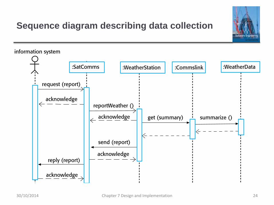
Sequence diagram describing data collection
Chapter 7 Design and Implementation 2430/10/2014
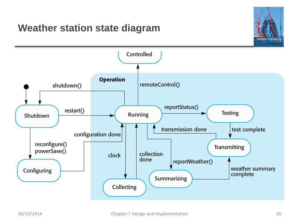
State diagrams
State diagrams are used to show how objects respond to different service requests and the state transitions triggered by these requests.
State diagrams are useful high-level models of a system or an object’s run-time behavior.
You don’t usually need a state diagram for all of the objects in the system. Many of the objects in a system are relatively simple and a state model adds unnecessary detail to the design.
Chapter 7 Design and Implementation 2530/10/2014
Weather station state diagram
Chapter 7 Design and Implementation 2630/10/2014
Interface specification
Object interfaces have to be specified so that the objects
and other components can be designed in parallel.
Designers should avoid designing the interface
representation but should hide this in the object itself.
Objects may have several interfaces which are
viewpoints on the methods provided.
The UML uses class diagrams for interface specification
but Java may also be used.
Chapter 7 Design and Implementation 2730/10/2014
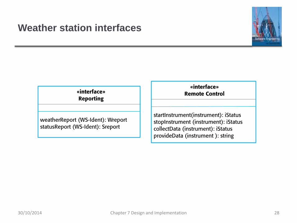
Weather station interfaces
Chapter 7 Design and Implementation 2830/10/2014
Design patterns
Chapter 7 Design and Implementation 2930/10/2014
Design patterns
A design pattern is a way of reusing abstract knowledge
about a problem and its solution.
A pattern is a description of the problem and the essence
of its solution.
It should be sufficiently abstract to be reused in different
settings.
Pattern descriptions usually make use of object-oriented
characteristics such as inheritance and polymorphism.
Chapter 7 Design and Implementation 3030/10/2014
Patterns
Patterns and Pattern Languages are ways to describe
best practices, good designs, and capture experience in
a way that it is possible for others to reuse this
experience.
Chapter 7 Design and Implementation 3130/10/2014
Pattern elements
Name
A meaningful pattern identifier.
Problem description.
Solution description.
Not a concrete design but a template for a design solution that
can be instantiated in different ways.
Consequences
The results and trade-offs of applying the pattern.
Chapter 7 Design and Implementation 3230/10/2014
The Observer pattern
Name
Observer.
Description
Separates the display of object state from the object itself.
Problem description
Used when multiple displays of state are needed.
Solution description
See slide with UML description.
Consequences
Optimisations to enhance display performance are impractical.
Chapter 7 Design and Implementation 3330/10/2014
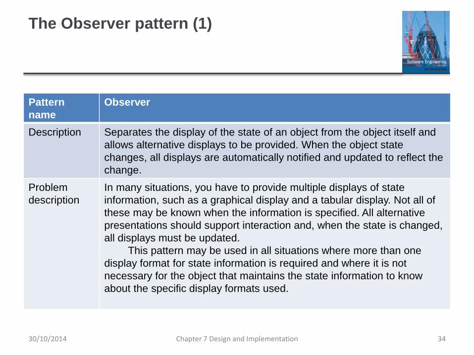
The Observer pattern (1)
Pattern
name
Observer
Description Separates the display of the state of an object from the object itself and
allows alternative displays to be provided. When the object state
changes, all displays are automatically notified and updated to reflect the
change.
Problem
description
In many situations, you have to provide multiple displays of state
information, such as a graphical display and a tabular display. Not all of
these may be known when the information is specified. All alternative
presentations should support interaction and, when the state is changed,
all displays must be updated.
This pattern may be used in all situations where more than one
display format for state information is required and where it is not
necessary for the object that maintains the state information to know
about the specific display formats used.
Chapter 7 Design and Implementation 3430/10/2014
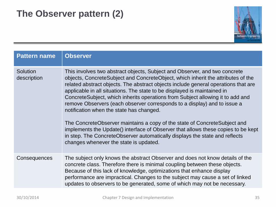
The Observer pattern (2)
Pattern name Observer
Solution
description
This involves two abstract objects, Subject and Observer, and two concrete
objects, ConcreteSubject and ConcreteObject, which inherit the attributes of the
related abstract objects. The abstract objects include general operations that are
applicable in all situations. The state to be displayed is maintained in
ConcreteSubject, which inherits operations from Subject allowing it to add and
remove Observers (each observer corresponds to a display) and to issue a
notification when the state has changed.
The ConcreteObserver maintains a copy of the state of ConcreteSubject and
implements the Update() interface of Observer that allows these copies to be kept
in step. The ConcreteObserver automatically displays the state and reflects
changes whenever the state is updated.
Consequences The subject only knows the abstract Observer and does not know details of the
concrete class. Therefore there is minimal coupling between these objects.
Because of this lack of knowledge, optimizations that enhance display
performance are impractical. Changes to the subject may cause a set of linked
updates to observers to be generated, some of which may not be necessary.
Chapter 7 Design and Implementation 3530/10/2014
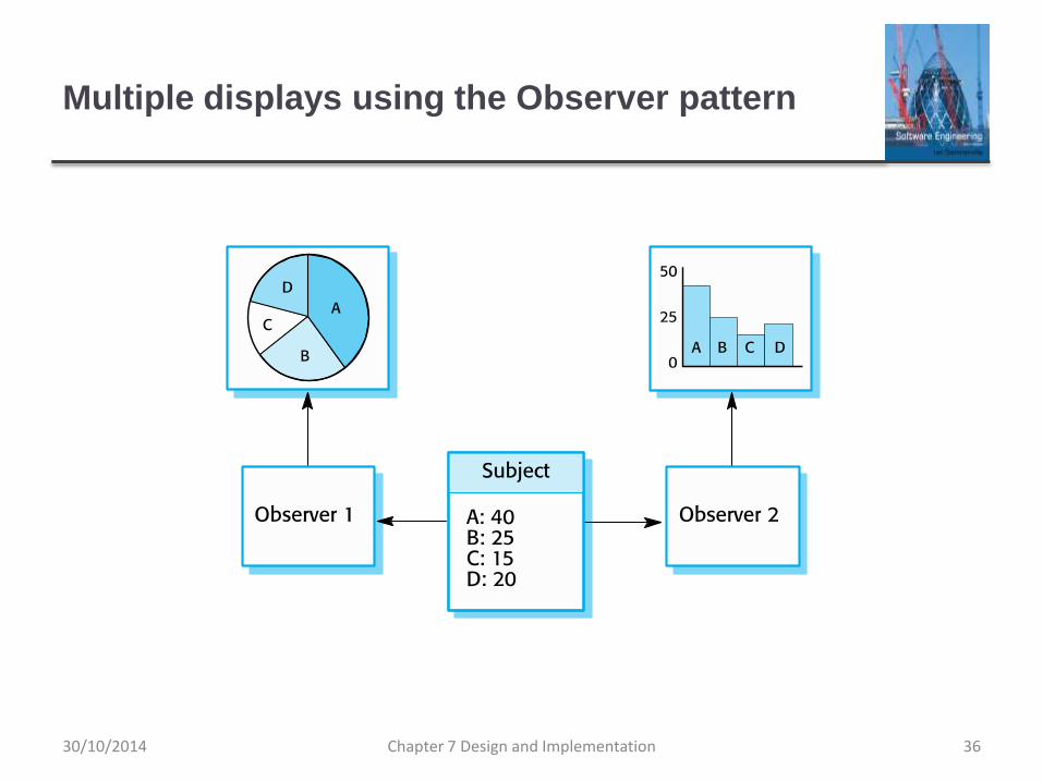
Multiple displays using the Observer pattern
Chapter 7 Design and Implementation 3630/10/2014
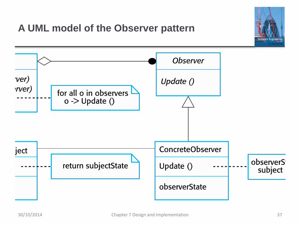
A UML model of the Observer pattern
Chapter 7 Design and Implementation 3730/10/2014
Design problems
To use patterns in your design, you need to recognize
that any design problem you are facing may have an
associated pattern that can be applied.
Tell several objects that the state of some other object has
changed (Observer pattern).
Tidy up the interfaces to a number of related objects that have
often been developed incrementally (Façade pattern).
Provide a standard way of accessing the elements in a
collection, irrespective of how that collection is implemented
(Iterator pattern).
Allow for the possibility of extending the functionality of an
existing class at run-time (Decorator pattern).
Chapter 7 Design and Implementation 3830/10/2014
Implementation issues
Chapter 7 Design and Implementation 3930/10/2014
Implementation issues
Focus here is not on programming, although this is
obviously important, but on other implementation issues
that are often not covered in programming texts:
Reuse Most modern software is constructed by reusing existing
components or systems. When you are developing software, you
should make as much use as possible of existing code.
Configuration management During the development process,
you have to keep track of the many different versions of each
software component in a configuration management system.
Host-target development Production software does not usually
execute on the same computer as the software development
environment. Rather, you develop it on one computer (the host
system) and execute it on a separate computer (the target
system).Chapter 7 Design and Implementation 4030/10/2014
Reuse
From the 1960s to the 1990s, most new software was
developed from scratch, by writing all code in a high-
level programming language.
The only significant reuse or software was the reuse of functions
and objects in programming language libraries.
Costs and schedule pressure mean that this approach
became increasingly unviable, especially for commercial
and Internet-based systems.
An approach to development based around the reuse of
existing software emerged and is now generally used for
business and scientific software.
Chapter 7 Design and Implementation 4130/10/2014
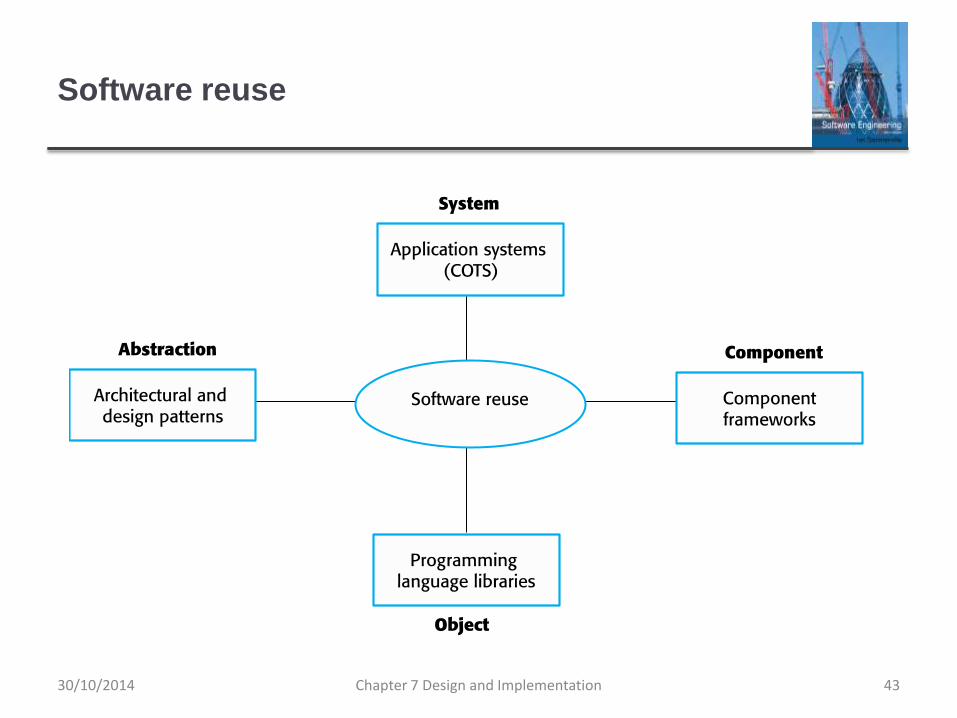
Reuse levels
The abstraction level
At this level, you don’t reuse software directly but use knowledge
of successful abstractions in the design of your software.
The object level
At this level, you directly reuse objects from a library rather than
writing the code yourself.
The component level
Components are collections of objects and object classes that
you reuse in application systems.
The system level
At this level, you reuse entire application systems.
Chapter 7 Design and Implementation 4230/10/2014
Software reuse
Chapter 7 Design and Implementation 4330/10/2014
Reuse costs
The costs of the time spent in looking for software to
reuse and assessing whether or not it meets your needs.
Where applicable, the costs of buying the reusable
software. For large off-the-shelf systems, these costs
can be very high.
The costs of adapting and configuring the reusable
software components or systems to reflect the
requirements of the system that you are developing.
The costs of integrating reusable software elements with
each other (if you are using software from different
sources) and with the new code that you have
developed. Chapter 7 Design and Implementation 4430/10/2014
Configuration management
Configuration management is the name given to the
general process of managing a changing software
system.
The aim of configuration management is to support the
system integration process so that all developers can
access the project code and documents in a controlled
way, find out what changes have been made, and
compile and link components to create a system.
See also Chapter 25.
Chapter 7 Design and Implementation 4530/10/2014
Configuration management activities
Version management, where support is provided to keep track
of the different versions of software components. Version
management systems include facilities to coordinate
development by several programmers.
System integration, where support is provided to help
developers define what versions of components are used to
create each version of a system. This description is then used
to build a system automatically by compiling and linking the
required components.
Problem tracking, where support is provided to allow users to
report bugs and other problems, and to allow all developers to
see who is working on these problems and when they are
fixed.
Chapter 7 Design and Implementation 4630/10/2014
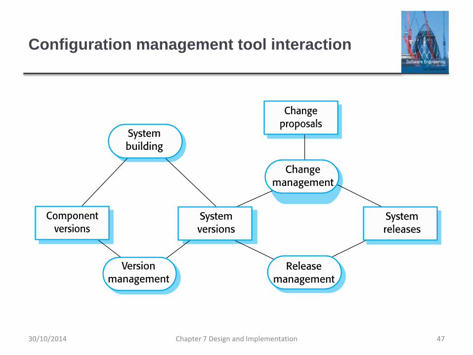
Configuration management tool interaction
Chapter 7 Design and Implementation 4730/10/2014
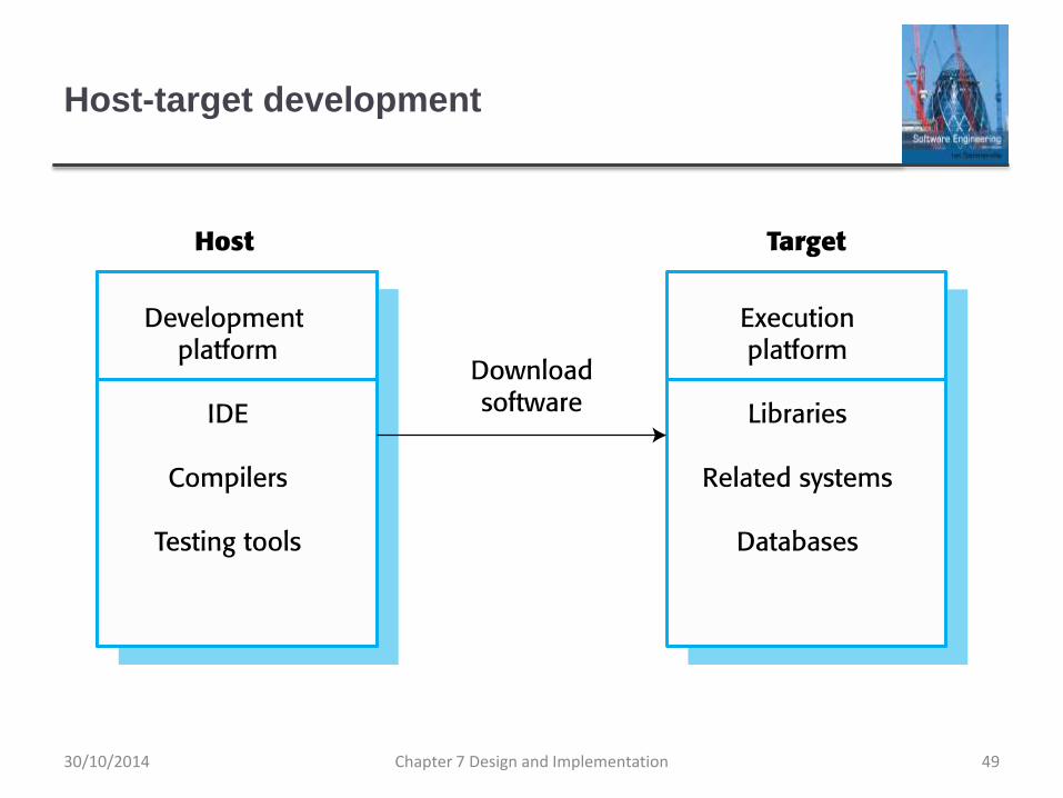
Host-target development
Most software is developed on one computer (the host),
but runs on a separate machine (the target).
More generally, we can talk about a development
platform and an execution platform.
A platform is more than just hardware.
It includes the installed operating system plus other supporting
software such as a database management system or, for
development platforms, an interactive development environment.
Development platform usually has different installed
software than execution platform; these platforms may
have different architectures.
Chapter 7 Design and Implementation 4830/10/2014
Host-target development
Chapter 7 Design and Implementation 4930/10/2014
Development platform tools
An integrated compiler and syntax-directed editing
system that allows you to create, edit and compile code.
A language debugging system.
Graphical editing tools, such as tools to edit UML
models.
Testing tools, such as Junit that can automatically run a
set of tests on a new version of a program.
Project support tools that help you organize the code for
different development projects.
Chapter 7 Design and Implementation 5030/10/2014

Integrated development environments (IDEs)
Software development tools are often grouped to create
an integrated development environment (IDE).
An IDE is a set of software tools that supports different
aspects of software development, within some common
framework and user interface.
IDEs are created to support development in a specific
programming language such as Java. The language IDE
may be developed specially, or may be an instantiation
of a general-purpose IDE, with specific language-support
tools.
Chapter 7 Design and Implementation 5130/10/2014
Component/system deployment factors
If a component is designed for a specific hardware architecture, or
relies on some other software system, it must obviously be deployed
on a platform that provides the required hardware and software
support.
High availability systems may require components to be deployed
on more than one platform. This means that, in the event of platform
failure, an alternative implementation of the component is available.
If there is a high level of communications traffic between
components, it usually makes sense to deploy them on the same
platform or on platforms that are physically close to one other. This
reduces the delay between the time a message is sent by one
component and received by another.
Chapter 7 Design and Implementation 5230/10/2014
Open source development
Chapter 7 Design and Implementation 5330/10/2014
Open source development
Open source development is an approach to software
development in which the source code of a software
system is published and volunteers are invited to
participate in the development process
Its roots are in the Free Software Foundation
(www.fsf.org), which advocates that source code should
not be proprietary but rather should always be available
for users to examine and modify as they wish.
Open source software extended this idea by using the
Internet to recruit a much larger population of volunteer
developers. Many of them are also users of the code.
Chapter 7 Design and Implementation 5430/10/2014
Open source systems
The best-known open source product is, of course, the
Linux operating system which is widely used as a server
system and, increasingly, as a desktop environment.
Other important open source products are Java, the
Apache web server and the mySQL database
management system.
Chapter 7 Design and Implementation 5530/10/2014
Open source issues
Should the product that is being developed make use of
open source components?
Should an open source approach be used for the
software’s development?
Chapter 7 Design and Implementation 5630/10/2014
Open source business
More and more product companies are using an open
source approach to development.
Their business model is not reliant on selling a software
product but on selling support for that product.
They believe that involving the open source community
will allow software to be developed more cheaply, more
quickly and will create a community of users for the
software.
Chapter 7 Design and Implementation 5730/10/2014
Open source licensing
A fundamental principle of open-source development is
that source code should be freely available, this does not
mean that anyone can do as they wish with that code.
Legally, the developer of the code (either a company or an
individual) still owns the code. They can place restrictions on
how it is used by including legally binding conditions in an open
source software license.
Some open source developers believe that if an open source
component is used to develop a new system, then that system
should also be open source.
Others are willing to allow their code to be used without this
restriction. The developed systems may be proprietary and sold
as closed source systems.
Chapter 7 Design and Implementation 5830/10/2014
License models
The GNU General Public License (GPL). This is a so-called
‘reciprocal’ license that means that if you use open source
software that is licensed under the GPL license, then you
must make that software open source.
The GNU Lesser General Public License (LGPL) is a variant
of the GPL license where you can write components that link
to open source code without having to publish the source of
these components.
The Berkley Standard Distribution (BSD) License. This is a
non-reciprocal license, which means you are not obliged to re-
publish any changes or modifications made to open source
code. You can include the code in proprietary systems that
are sold.
Chapter 7 Design and Implementation 5930/10/2014
License management
Establish a system for maintaining information about
open-source components that are downloaded and
used.
Be aware of the different types of licenses and
understand how a component is licensed before it is
used.
Be aware of evolution pathways for components.
Educate people about open source.
Have auditing systems in place.
Participate in the open source community.
Chapter 7 Design and Implementation 6030/10/2014
Key points
Software design and implementation are inter-leaved activities. The
level of detail in the design depends on the type of system and
whether you are using a plan-driven or agile approach.
The process of object-oriented design includes activities to design
the system architecture, identify objects in the system, describe the
design using different object models and document the component
interfaces.
A range of different models may be produced during an object-
oriented design process. These include static models (class models,
generalization models, association models) and dynamic models
(sequence models, state machine models).
Component interfaces must be defined precisely so that other
objects can use them. A UML interface stereotype may be used to
define interfaces.Chapter 7 Design and Implementation 6130/10/2014
Key points
When developing software, you should always consider the
possibility of reusing existing software, either as components,
services or complete systems.
Configuration management is the process of managing changes to
an evolving software system. It is essential when a team of people
are cooperating to develop software.
Most software development is host-target development. You use an
IDE on a host machine to develop the software, which is transferred
to a target machine for execution.
Open source development involves making the source code of a
system publicly available. This means that many people can
propose changes and improvements to the software.
Chapter 7 Design and Implementation 6230/10/2014

![INSTALL GUIDE OEM CH RS CH7 ADS CH7 EN - …cdncontent2.idatalink.com/.../RS-CH7/...CH7-[ADS-CH7]-EN_20160811.pdfU.S. Patent No. 8,856,780 BOX CONTENTS](https://img.pdfslide.us/doc/110x75/5af03fd77f8b9ad0618dd202/install-guide-oem-ch-rs-ch7-ads-ch7-en-ads-ch7-en20160811pdfus-patent.jpg)