Embed Size (px)
Citation preview
– 15 –
SCHEM ATIC DIAGRAM – 1 (M AIN)
– 17 –
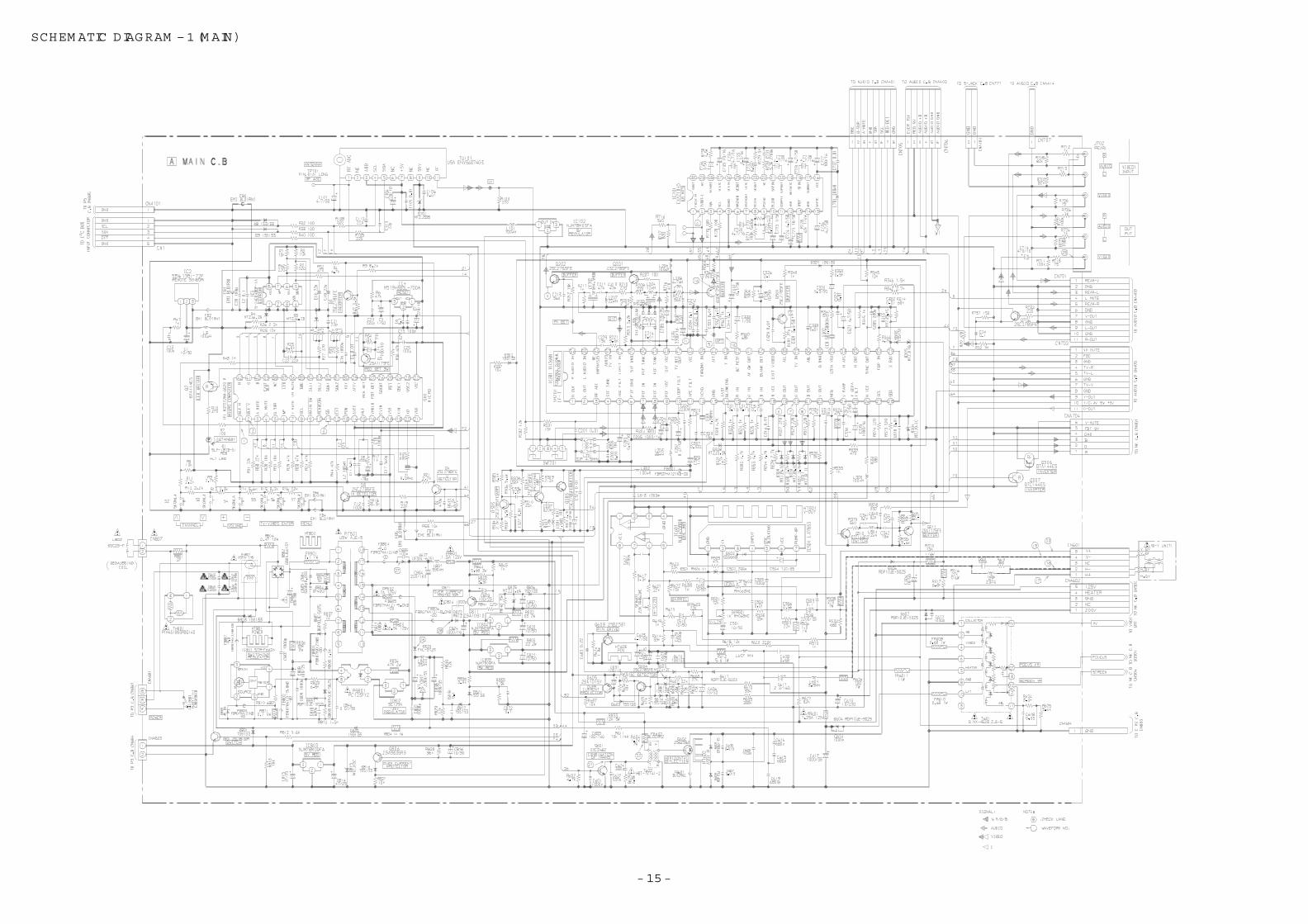
SCHEM ATIC DIAGRAM – 2 (AUDIO)
– 19 –
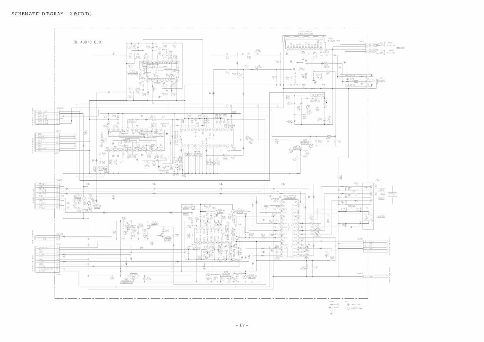
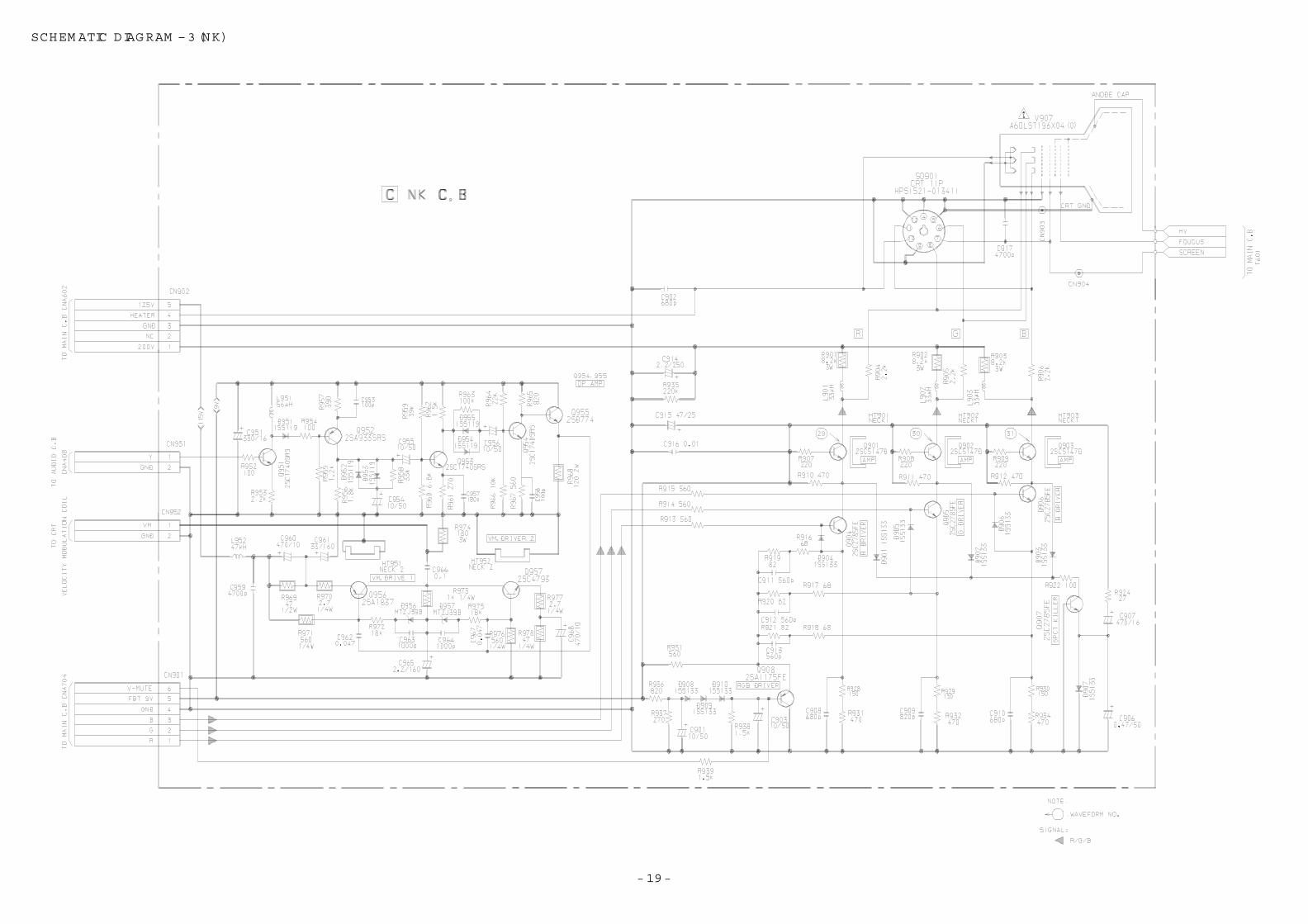
SCHEM ATIC DIAGRAM – 3 (NK)
– 21 –
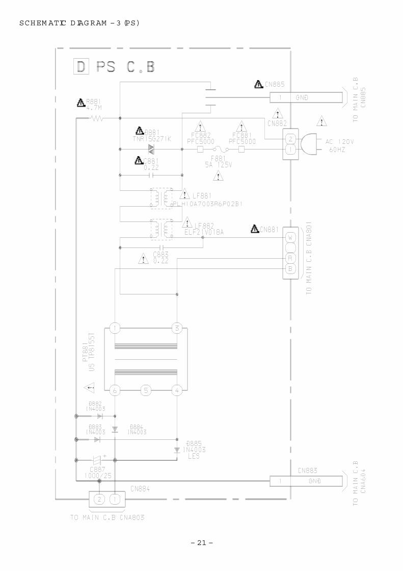
SCHEM ATIC DIAGRAM – 3 (PS)
– 22 –
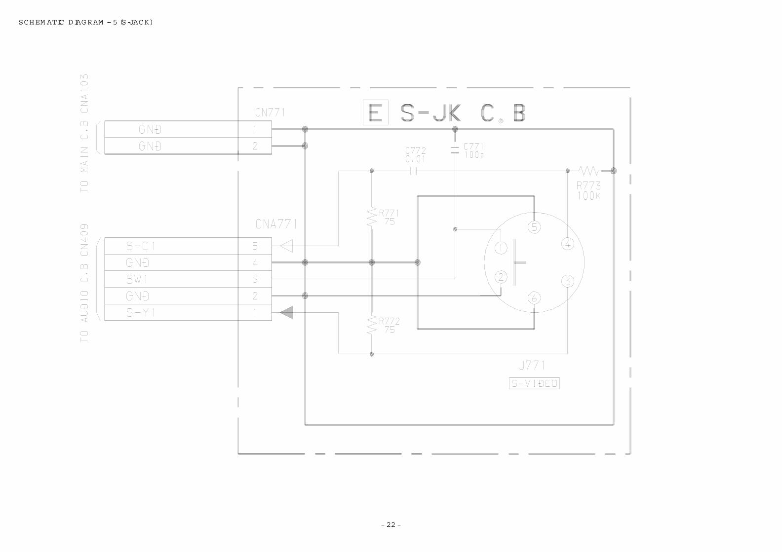
SCHEM ATIC DIAGRAM – 5 (S-JACK)
– 23 –
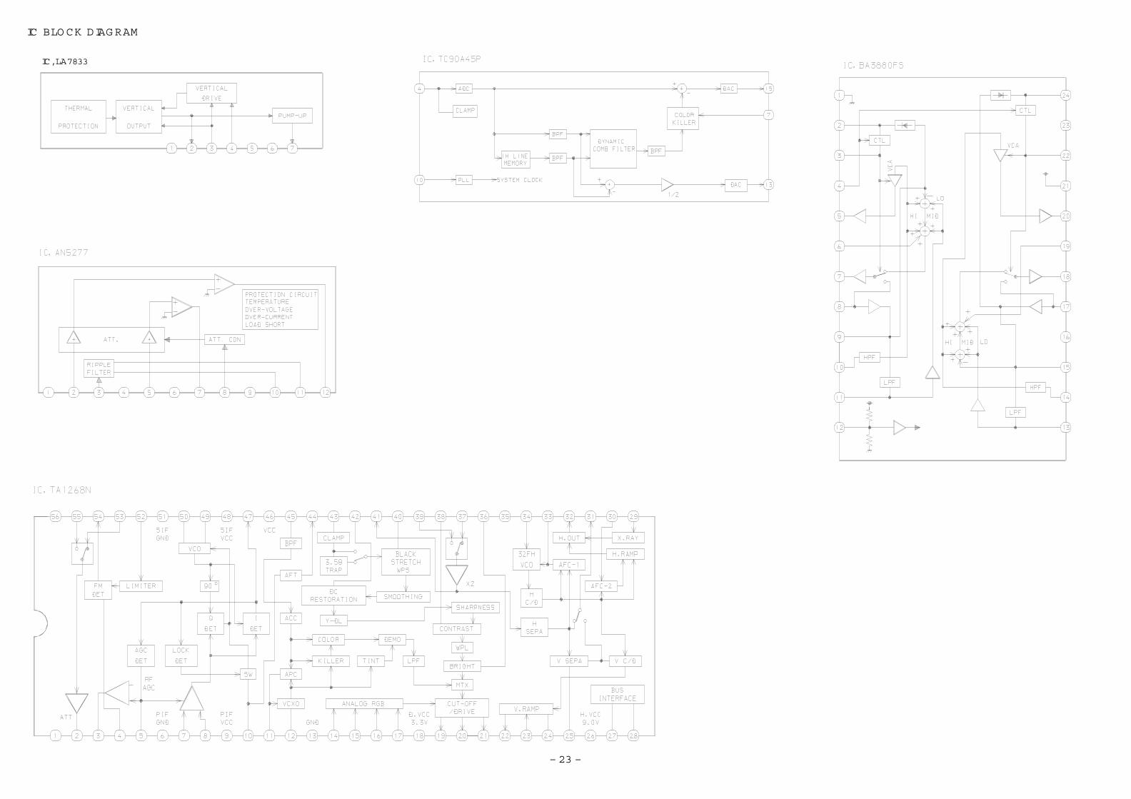
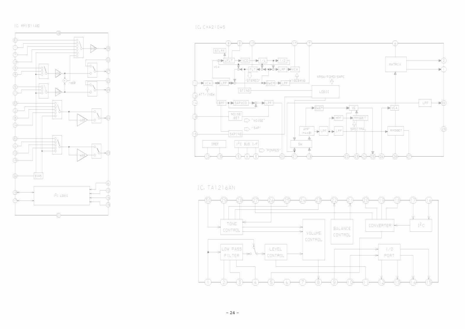
IC BLOCK DIAGRAM
IC, LA7833
– 24 –
– 3 –
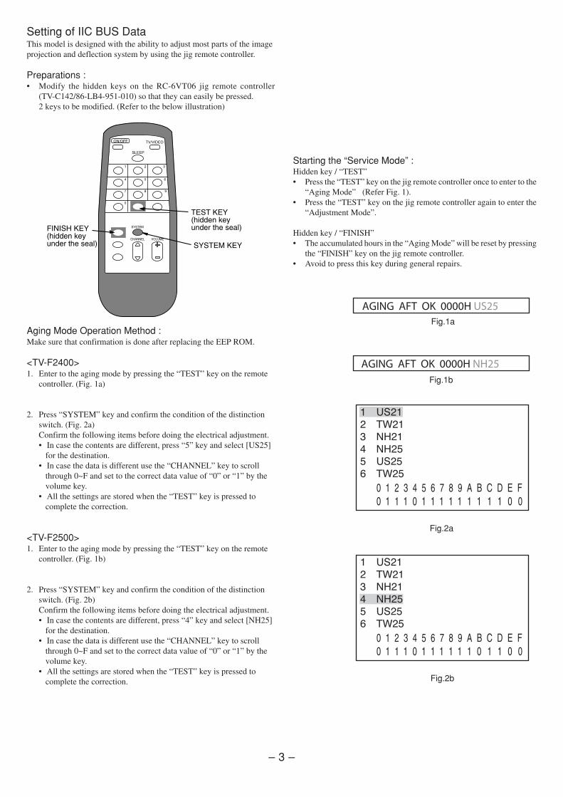
Setting of IIC BUS DataThis model is designed with the ability to adjust most parts of the imageprojection and deflection system by using the jig remote controller.
Preparations :• Modify the hidden keys on the RC-6VT06 jig remote controller
(TV-C142/86-LB4-951-010) so that they can easily be pressed.2 keys to be modified. (Refer to the below illustration)
Starting the “Service Mode” :Hidden key / “TEST”• Press the “TEST” key on the jig remote controller once to enter to the
“Aging Mode” (Refer Fig. 1).• Press the “TEST” key on the jig remote controller again to enter the
“Adjustment Mode”.
Hidden key / “FINISH”• The accumulated hours in the “Aging Mode” will be reset by pressing
the “FINISH” key on the jig remote controller.• Avoid to press this key during general repairs.
Aging Mode Operation Method :Make sure that confirmation is done after replacing the EEP ROM.
<TV-F2400>1. Enter to the aging mode by pressing the “TEST” key on the remote
controller. (Fig. 1a)
2. Press “SYSTEM” key and confirm the condition of the distinctionswitch. (Fig. 2a)Confirm the following items before doing the electrical adjustment.• In case the contents are different, press “5” key and select [US25]
for the destination.• In case the data is different use the “CHANNEL” key to scroll
through 0~F and set to the correct data value of “0” or “1” by thevolume key.
• All the settings are stored when the “TEST” key is pressed tocomplete the correction.
<TV-F2500>1. Enter to the aging mode by pressing the “TEST” key on the remote
controller. (Fig. 1b)
2. Press “SYSTEM” key and confirm the condition of the distinctionswitch. (Fig. 2b)Confirm the following items before doing the electrical adjustment.• In case the contents are different, press “4” key and select [NH25]
for the destination.• In case the data is different use the “CHANNEL” key to scroll
through 0~F and set to the correct data value of “0” or “1” by thevolume key.
• All the settings are stored when the “TEST” key is pressed tocomplete the correction.
Fig.1a
Fig.2a
Fig.2b
AGING AFT OK 0000H US25
AGING AFT OK 0000H NH25Fig.1b
� ����
� ����
� ���
���
� ����
� ����
� ����
� ����
� ���
���
� ����
� ����
– 4 –
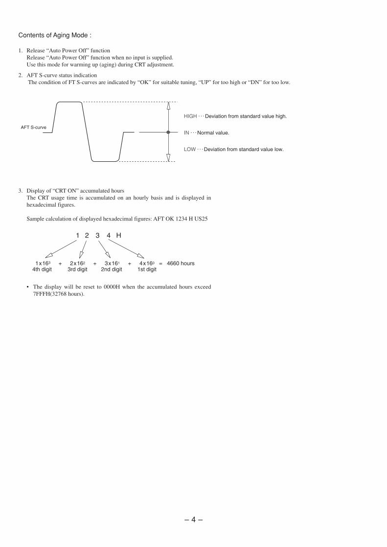
3. Display of “CRT ON” accumulated hoursThe CRT usage time is accumulated on an hourly basis and is displayed inhexadecimal figures.
Sample calculation of displayed hexadecimal figures: AFT OK 1234 H US25
• The display will be reset to 0000H when the accumulated hours exceed7FFFH(32768 hours).
Contents of Aging Mode :
1. Release “Auto Power Off” functionRelease “Auto Power Off” function when no input is supplied.Use this mode for warming up (aging) during CRT adjustment.
2. AFT S-curve status indication The condition of FT S-curves are indicated by “OK” for suitable tuning, “UP” for too high or “DN” for too low.
– 5 –
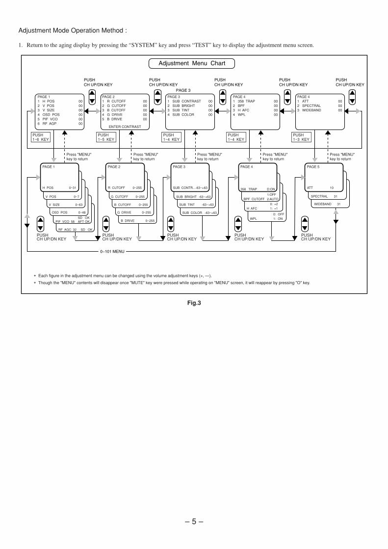
Adjustment Mode Operation Method :
1. Return to the aging display by pressing the “SYSTEM” key and press “TEST” key to display the adjustment menu screen.
PAGE 11 H POS 002 V POS 003 V SIZE 004 OSD POS 005 PIF VCO 006 RF AGP 00
PAGE 21 R CUTOFF 002 G CUTOFF 003 B CUTOFF 004 G DRIVE 005 B DRIVE 00
ENTER CONTRAST
PAGE 31 SUB CONTRAST 002 SUB BRIGHT 003 SUB TINT 004 SUB COLOR 00
PAGE 41 358 TRAP 002 BPF 003 H AFC 004 WPL 00
PAGE 41 ATT 002 SPECTRAL 003 WIDEBAND 00
PUSH1~6 KEY
PUSH1~5 KEY
PUSH1~4 KEY
PUSH1~4 KEY
PUSH1~3 KEY
PUSHCH UP/DN KEY
PUSHCH UP/DN KEY
PUSHCH UP/DN KEY
PUSHCH UP/DN KEY
PUSHCH UP/DN KEY
H POS 0~31
V POS 0~7
V SIZE 0~63
OSD POS 0~48
SD OKPIF VCO 58 AFT OK
RF AGC 32 SD OK
PAGE 1
R CUTOFF 0~255
G CUTOFF 0~255
B CUTOFF 0~255
G DRIVE 0~255
PAGE 2
B DRIVE 0~255
ATT 10
PAGE 5
SUB CONTR...-63~+63
PAGE 3
SUB BRIGHT -63~+63
SUB TINT -63~+63
SUB COLOR -63~+63
358 TRAP D:ON
PAGE 4
1:OFFBPF CUTOFF 2:AUTO
0: OFFWPL 1: ON
0: +2H AFC 1: +1
SPECTRAL 31
WIDEBAND 31
Press "MENU" key to return
Press "MENU" key to return
Press "MENU" key to return
Press "MENU" key to return
Press "MENU" key to return
* Each figure in the adjustment menu can be changed using the volume adjustment keys (+, —).
* Though the "MENU" contents will disappear once "MUTE" key were pressed while operating on "MENU" screen, it will reappear by pressing "O" key.
Fig.3
– 6 –
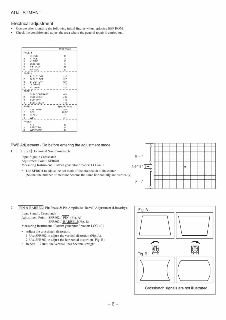
PWB Adjustment / Do before entering the adjustment mode
1. H SIZE Horizontal Size Crosshatch
Input Signal : CrosshatchAdjustment Point : SFR601Measuring Instrument : Pattern generator / reader: LCG-401
• Use SFR601 to adjust the dot mark of the crosshatch to the center.(So that the number of measure become the same horizontally and vertically)
2. PIN & BARREL Pin Phase & Pin Amplitude (Barrel) Adjustment (Linearity).
Input Signal : CrosshatchAdjustment Point : SFR602 / PIN (Fig. A)
SFR603 / BARREL (Fig. B)Measuring Instrument : Pattern generator / reader: LCG-401
• Adjust the crosshatch distortion.1. Use SFR602 to adjust the vertical distortion (Fig. A).2. Use SFR603 to adjust the horizontal distortion (Fig. B).
• Repeat 1~2 until the vertical lines become straight.
Electrical adjustment:• Operate after inputting the following initial figures when replacing EEP ROM.• Check the condition and adjust the area where the general repair is carried out.
6 ~ 7
6 ~ 7
Center
Fig. A
Fig. B
Crosshatch signals are not illustrated
ADJUSTMENT
Initial Value
PAGE 11. H POS 162. V POS 33. V SIZE 304. OSD POS 65. PIF VCO 586. RF AGC 32
PAGE 21. R CUT OFF 1272. G CUT OFF 1273. B CUT OFF 1274. G DRIVE 1275. B DRIVE 127
PAGE 31. SUB CONTRAST – 52. SUB BRIGHT + 323. SUB TINT + 164. SUB COLOR + 16
PAGE 4 Specific Value1. 3.58 TRAP OFF2. BPF AUTO3. H AFC + 14. WPL OFF
PAGE 51. ATT 102. SPECTRAL 243. WIDEBAND 44
– 7 –
PAGE 1
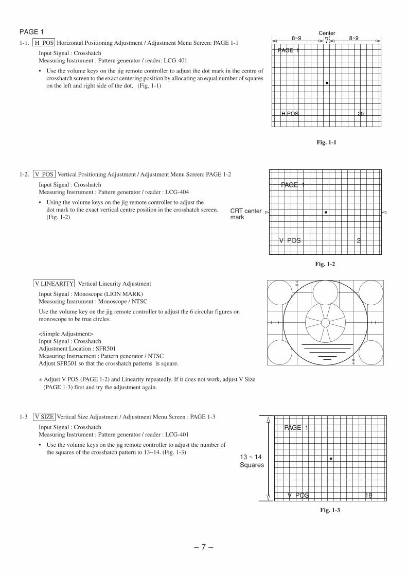
1-1. H POS Horizontal Positioning Adjustment / Adjustment Menu Screen: PAGE 1-1
Input Signal : CrosshatchMeasuring Instrument : Pattern generator / reader: LCG-401
• Use the volume keys on the jig remote controller to adjust the dot mark in the centre ofcrosshatch screen to the exact centering position by allocating an equal number of squareson the left and right side of the dot. (Fig. 1-1)
1-2. V POS Vertical Positioning Adjustment / Adjustment Menu Screen: PAGE 1-2
Input Signal : CrosshatchMeasuring Instrument : Pattern generator / reader : LCG-404
• Using the volume keys on the jig remote controller to adjust thedot mark to the exact vertical centre position in the crosshatch screen.(Fig. 1-2)
V LINEARITY Vertical Linearity Adjustment
Input Signal : Monoscope (LION MARK)Measuring Instrument : Monoscope / NTSC
Use the volume key on the jig remote controller to adjust the 6 circular figures onmonoscope to be true circles.
<Simple Adjustment>Input Signal : CrosshatchAdjustment Location : SFR501Measuring Instrucment : Pattern generator / NTSCAdjust SFR501 so that the crosshatch patterns is square.
* Adjust V POS (PAGE 1-2) and Linearity repeatedly. If it does not work, adjust V Size (PAGE 1-3) first and try the adjustment again.
1-3 V SIZE Vertical Size Adjustment / Adjustment Menu Screen : PAGE 1-3
Input Signal : CrosshatchMeasuring Instrument : Pattern generator / reader : LCG-401
• Use the volume keys on the jig remote controller to adjust the number ofthe squares of the crosshatch pattern to 13~14. (Fig. 1-3)
PAGE 1
V POS 18
13 ~ 14 Squares
CRT center mark
PAGE 1
V POS 2
Fig. 1-1
Fig. 1-2
Fig. 1-3
PAGE 1
H POS 20
8~9 8~9Center
– 8 –
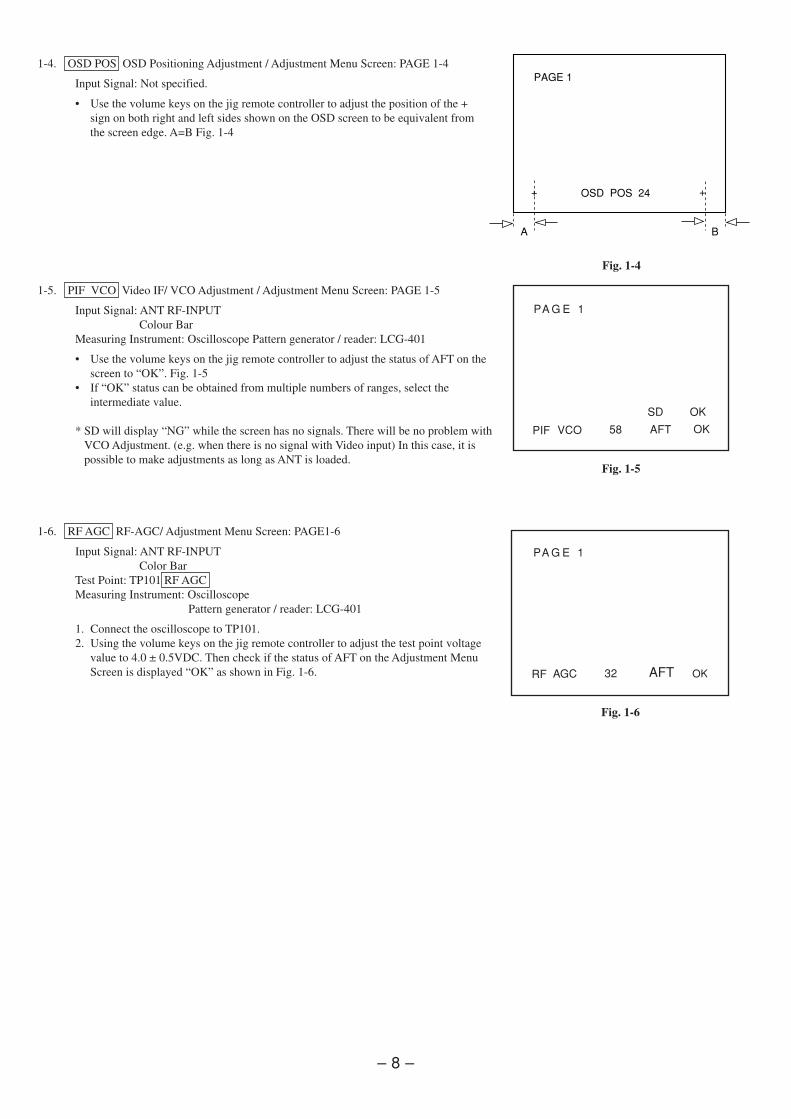
1-4. OSD POS OSD Positioning Adjustment / Adjustment Menu Screen: PAGE 1-4
Input Signal: Not specified.
• Use the volume keys on the jig remote controller to adjust the position of the +sign on both right and left sides shown on the OSD screen to be equivalent fromthe screen edge. A=B Fig. 1-4
1-5. PIF VCO Video IF/ VCO Adjustment / Adjustment Menu Screen: PAGE 1-5
Input Signal: ANT RF-INPUTColour Bar
Measuring Instrument: Oscilloscope Pattern generator / reader: LCG-401
• Use the volume keys on the jig remote controller to adjust the status of AFT on thescreen to “OK”. Fig. 1-5
• If “OK” status can be obtained from multiple numbers of ranges, select theintermediate value.
* SD will display “NG” while the screen has no signals. There will be no problem withVCO Adjustment. (e.g. when there is no signal with Video input) In this case, it is
possible to make adjustments as long as ANT is loaded.
1-6. RF AGC RF-AGC/ Adjustment Menu Screen: PAGE1-6
Input Signal: ANT RF-INPUTColor Bar
Test Point: TP101 RF AGCMeasuring Instrument: Oscilloscope
Pattern generator / reader: LCG-401
1. Connect the oscilloscope to TP101.2. Using the volume keys on the jig remote controller to adjust the test point voltage
value to 4.0 ± 0.5VDC. Then check if the status of AFT on the Adjustment MenuScreen is displayed “OK” as shown in Fig. 1-6.
PIF VCO 58
SD
AFT
OK
OK
PA G E 1
PA G E 1
RF AGC 32 AFT OK
Fig. 1-4
Fig. 1-5
Fig. 1-6
PAGE 1
OSD POS 24 +
A B
+
– 9 –
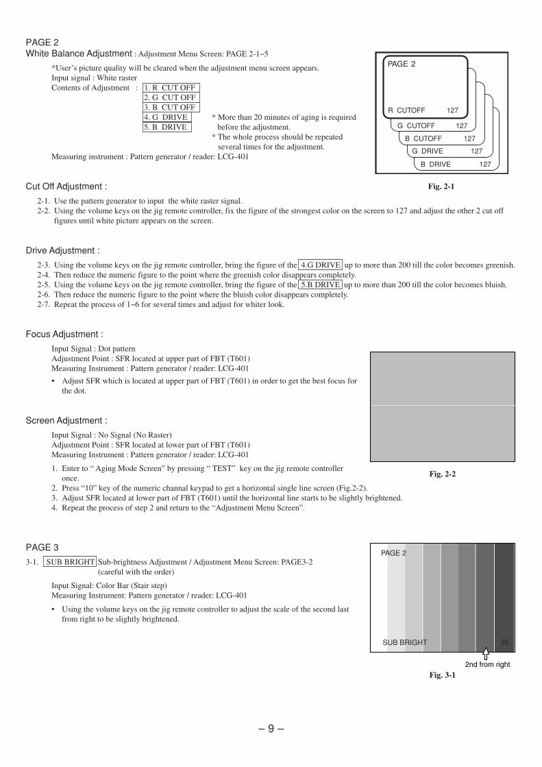
PAGE 2White Balance Adjustment : Adjustment Menu Screen: PAGE 2-1~5
*User’s picture quality will be cleared when the adjustment menu screen appears.Input signal : White rasterContents of Adjustment : 1. R CUT OFFContents of Adjustment : 2. G CUT OFFContents of Adjustment : 3. B CUT OFFContents of Adjustment : 4. G DRIVE * More than 20 minutes of aging is required
5. B DRIVE before the adjustment.Contents of Adjustment * The whole process should be repeated
several times for the adjustment.Measuring instrument : Pattern generator / reader: LCG-401
Cut Off Adjustment :
2-1. Use the pattern generator to input the white raster signal.2-2. Using the volume keys on the jig remote controller, fix the figure of the strongest color on the screen to 127 and adjust the other 2 cut off
figures until white picture appears on the screen.
Drive Adjustment :
2-3. Using the volume keys on the jig remote controller, bring the figure of the 4.G DRIVE up to more than 200 till the color becomes greenish.2-4. Then reduce the numeric figure to the point where the greenish color disappears completely.2-5. Using the volume keys on the jig remote controller, bring the figure of the 5.B DRIVE up to more than 200 till the color becomes bluish.2-6. Then reduce the numeric figure to the point where the bluish color disappears completely.2-7. Repeat the process of 1~6 for several times and adjust for whiter look.
Focus Adjustment :
Input Signal : Dot patternAdjustment Point : SFR located at upper part of FBT (T601)Measuring Instrument : Pattern generator / reader: LCG-401
• Adjust SFR which is located at upper part of FBT (T601) in order to get the best focus forthe dot.
Screen Adjustment :
Input Signal : No Signal (No Raster)Adjustment Point : SFR located at lower part of FBT (T601)Measuring Instrument : Pattern generator / reader: LCG-401
1. Enter to “ Aging Mode Screen” by pressing “ TEST” key on the jig remote controlleronce.
2. Press “10” key of the numeric channal keypad to get a horizontal single line screen (Fig.2-2).3. Adjust SFR located at lower part of FBT (T601) until the horizontal line starts to be slightly brightened.4. Repeat the process of step 2 and return to the “Adjustment Menu Screen”.
PAGE 3
3-1. SUB BRIGHT Sub-brightness Adjustment / Adjustment Menu Screen: PAGE3-2(careful with the order)
Input Signal: Color Bar (Stair step)Measuring Instrument: Pattern generator / reader: LCG-401
• Using the volume keys on the jig remote controller to adjust the scale of the second lastfrom right to be slightly brightened.
R CUTOFF 0~255
G CUTOFF 0~255
B CUTOFF 0~255
G DRIVE 0~255
PAGE 2
B DRIVE 0~255
R CUTOFF 127
G CUTOFF 127
B CUTOFF 127
G DRIVE 127
PAGE 2
B DRIVE 127
Fig. 2-2
PAGE 2
35SUB BRIGHT
Fig. 3-1
Fig. 2-1
– 10 –
Fig. 3-2
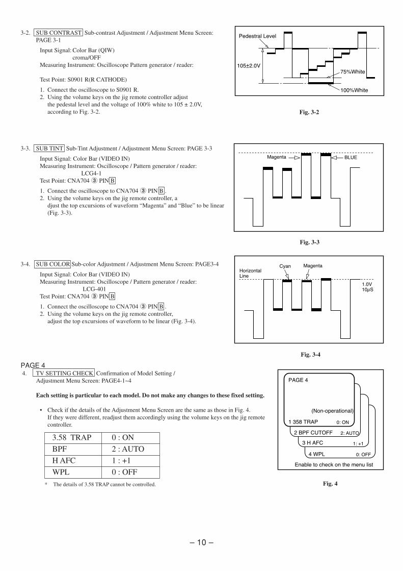
3-2. SUB CONTRAST Sub-contrast Adjustment / Adjustment Menu Screen:PAGE 3-1
Input Signal: Color Bar (QIW)croma/OFF
Measuring Instrument: Oscilloscope Pattern generator / reader:
Test Point: S0901 R(R CATHODE)
1. Connect the oscilloscope to S0901 R.2. Using the volume keys on the jig remote controller adjust
the pedestal level and the voltage of 100% white to 105 ± 2.0V,according to Fig. 3-2.
3-3. SUB TINT Sub-Tint Adjustment / Adjustment Menu Screen: PAGE 3-3
Input Signal: Color Bar (VIDEO IN)Measuring Instrument: Oscilloscope / Pattern generator / reader:
LCG4-1Test Point: CNA704 3 PIN B
1. Connect the oscilloscope to CNA704 3 PIN B .2. Using the volume keys on the jig remote controller, a
djust the top excursions of waveform “Magenta” and “Blue” to be linear(Fig. 3-3).
3-4. SUB COLOR Sub-color Adjustment / Adjustment Menu Screen: PAGE3-4
Input Signal: Color Bar (VIDEO IN)Measuring Instrument: Oscilloscope / Pattern generator / reader:
LCG-401Test Point: CNA704 3 PIN B
1. Connect the oscilloscope to CNA704 3 PIN B .2. Using the volume keys on the jig remote controller,
adjust the top excursions of waveform to be linear (Fig. 3-4).
PAGE 4 4. TV SETTING CHECK Confirmation of Model Setting /
Adjustment Menu Screen: PAGE4-1~4
Each setting is particular to each model. Do not make any changes to these fixed setting.
• Check if the details of the Adjustment Menu Screen are the same as those in Fig. 4.If they were different, readjust them accordingly using the volume keys on the jig remotecontroller.
Fig. 3-3
Fig. 3-4
Fig. 4* The details of 3.58 TRAP cannot be controlled.
3.58 TRAP 0 : ON
BPF 2 : AUTO
H AFC 1 : +1
WPL 0 : OFF
���������
���� �������
��� �
��������������
� ��� ���� ��
����
���
� ��
��� ������
� � ���
� ���
���� �
��������� !"�� #$
�� %#� !� &'�&( �� !'� )��* #"+!
��������
������
��� �
– 11 –
PAGE 5
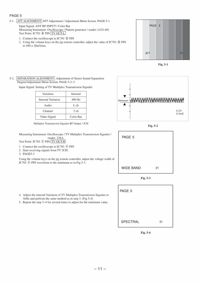
5-1. ATT ALIGNMENT ATT Adjustment / Adjustment Menu Screen: PAGE 5-1
Input Signal: ANT RF-INPUT / Color BarMeasuring Instrument: Oscilloscope / Pattern generator / reader: LCG-401Test Point: IC701 2 PIN TV OUT-L
1. Connect the oscilloscope to IC701 2 PIN2. Using the volume keys on the jig remote controller, adjust the value of IC701 2 PIN
to 490 ± 20mVrms.
5-2. SEPARATION ALIGNMENT Adjustment of Stereo Sound SeparationDegree/Adjustment Menu Screen: PAGE 5-2~3
Input Signal: Setting of TV Multiplex Transmission Signaler
Multiplex Transmission Signaler RF Output / 2CH
Measuring Instrument: Oscilloscope / TV Multiplex Transmission Signaler /reader: 236A
Test Point: IC701 1 PIN TV OUT-R
1. Connect the oscilloscope to IC701 1 PIN2. Start receiving signals from TV 2CH.3. PAGE5-3
Using the volume keys on the jig remote controller, adjust the voltage width ofIC7011 PIN waveform to the minimum as in Fig 5-3.
4. Adjust the internal Variation of TV Multiplex Transmission Signaler to1kHz and perfrom the same method as in step 3. (Fig 5-4)
5. Repeat the step 3~4 for several times to adjust for the minimum value.
Fig. 5-3
PAGE 5
WIDE BAND 31
PAGE 5
10ATT
Variation Internal
Internal Variation 400 Hz
Audio L ch
Channel 2 ch
Video Signal Color Bar
Minimum
0.2V
0.5mS
Fig. 5-1
Fig. 5-2
PAGE 5
SPECTRAL 31
Fig. 5-4
– 12 –
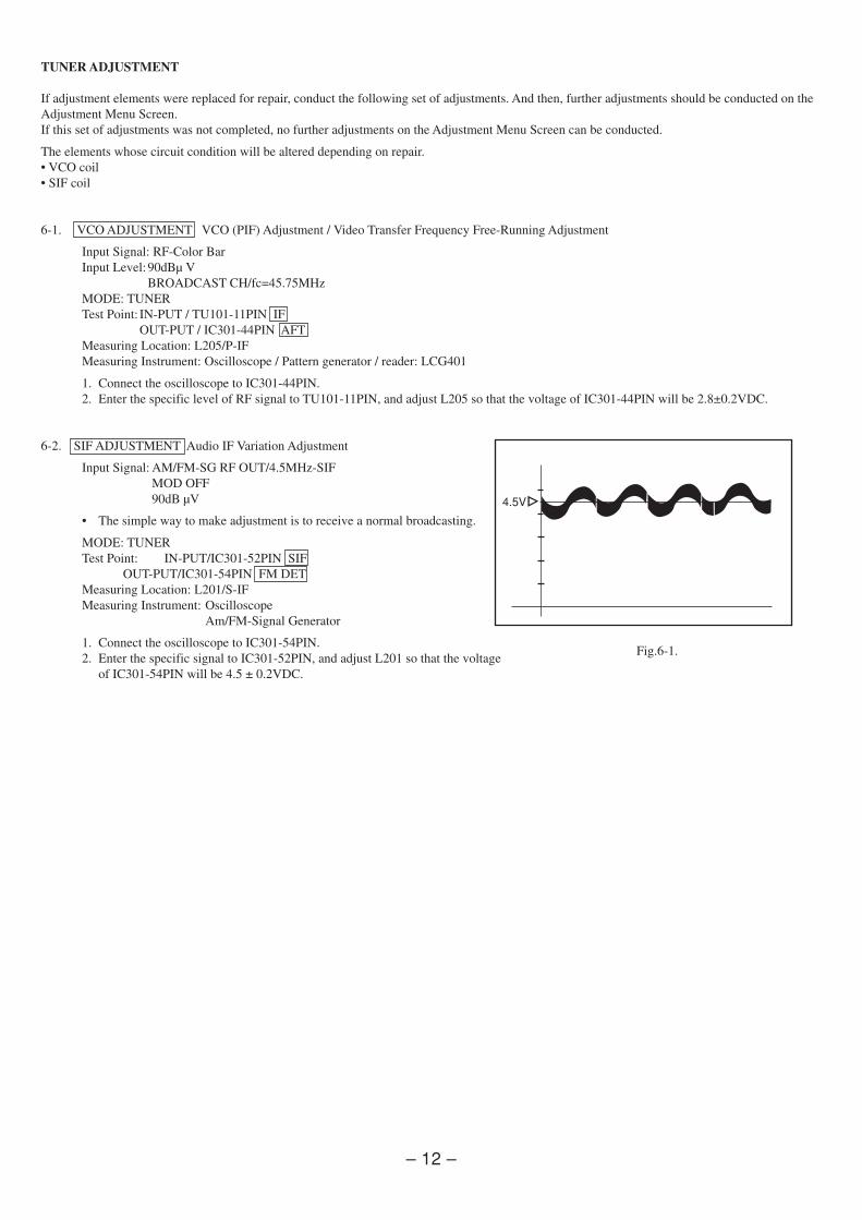
TUNER ADJUSTMENT
If adjustment elements were replaced for repair, conduct the following set of adjustments. And then, further adjustments should be conducted on theAdjustment Menu Screen.If this set of adjustments was not completed, no further adjustments on the Adjustment Menu Screen can be conducted.
The elements whose circuit condition will be altered depending on repair.• VCO coil• SIF coil
6-1. VCO ADJUSTMENT VCO (PIF) Adjustment / Video Transfer Frequency Free-Running Adjustment
Input Signal: RF-Color BarInput Level:90dBµ V
BROADCAST CH/fc=45.75MHzMODE: TUNERTest Point: IN-PUT / TU101-11PIN IF
OUT-PUT / IC301-44PIN AFTMeasuring Location: L205/P-IFMeasuring Instrument: Oscilloscope / Pattern generator / reader: LCG401
1. Connect the oscilloscope to IC301-44PIN.2. Enter the specific level of RF signal to TU101-11PIN, and adjust L205 so that the voltage of IC301-44PIN will be 2.8±0.2VDC.
6-2. SIF ADJUSTMENT Audio IF Variation Adjustment
Input Signal: AM/FM-SG RF OUT/4.5MHz-SIFMOD OFF90dB µV
• The simple way to make adjustment is to receive a normal broadcasting.
MODE: TUNERTest Point: IN-PUT/IC301-52PIN SIF
OUT-PUT/IC301-54PIN FM DETMeasuring Location: L201/S-IFMeasuring Instrument: Oscilloscope
Am/FM-Signal Generator
1. Connect the oscilloscope to IC301-54PIN.2. Enter the specific signal to IC301-52PIN, and adjust L201 so that the voltage
of IC301-54PIN will be 4.5 ± 0.2VDC.
Fig.6-1.
4.5V