Embed Size (px)
Citation preview

STEAM TURBINE OPERATIONSTRANSAS 4000

Main Engine

Type Cross-compound, double reduction geared steam turbine (Kawasaki UA-400 as prototype)
Output MCR, kW 29,450
- H.P. turbine 5,075R.P.M.: - L.P. turbine 3,350 - Propeller 90,0
Output NCR, kW 25,040 at 85,3 R.P.M.
Steam conditions at inlet 57.4 bar, 515 ºC
Full astern conditions 70 % of ahead M.C.R. r.p.m. for period of at least two hours
Condenser vacuum at top (pump cooling) 722 mm Hg Vac. at M.C.R.
Main boiler 2 x Two-drum, water tube marine boiler with dual-fuel burners with internal
Economizer (Mitsubishi MB-4E as prototype)
Superheated steam 61.5 bar/515 ºC/ 63,500 kg/h at M.C.R. condition
Propeller FPP

AUX Page, Compressed Air System1. Check that the compressed air cylinders are filled, replenish them as required;2. Supply compressed air to the control system and for fuel oil atomising by opening the compressed air supply valves: Control Air Distribution Valve and Service & Atomizing Air Distribution Valve.3. Put the compressor operation control mode selection switches to the “AUTO”position.

MT Page, Lubrication Oil System
Preparation of the lubricating system and hydraulic control system:1. In the lubricating oil temperature controller group set the lubricating oil temperature in the system at 40–45 ºС.2. In the Manual control mode turn on PUMP 1 and put the control mode selection switch to the “AUTO” position.3. Put Lubricating Oil Cooler 1 into operation and put the temperature control selection mode to the “AUTO” position.4. Open the valve for feeding oil to the Man. Oil control system.5. Monitor the oil level in the gravity tank (see the spy-hole), oil temperature and pressure at the turbine inlet.

CS Page, Sea Water System
1. Check opening of sea chests at the pumps suction.2. In the Manual control mode, switch main sea water circulation PUMP 1 to LOW FLOW and put the pump operation mode switch to the “AUTO” position.3. Open the cooling water supply valves:
– to the Main Condenser (open the Main Condenser Cooling Flow valve);– to the atmospheric condenser (with the “TO ATM. CONDENSER” button);
4. Monitor pressure after the pumps and water temperature at the condenseroutlet;5. In the Manual control mode, turn on Sea Water Cooling Pump 1 by using the “PUMP 1” button and put the pump operation mode switch to the “AUTO” position;6. Open the valves for supplying cooling water to Central FW Cooler 1 and Vacuum Unit Cooler;7. Monitor pressure after the pumps;8. Connect power supply to anodic tank 1 or 2;9. Turn on the ship hull anodic protection by using the “PORT” and (or) “STBD” button.

CS Page, Central Fresh Water Cooling System
1. In the Manual control mode, turn on the main fresh water circulation pump (PUMP 1) and put the pumps operation mode switch to the “AUTO” position.2. Open the cooling water supply pumps:
• to the fresh water cooler (by opening the FW COOLER 1 valve);• to the turbine lubricating oil cooler (by pressing the “MT LO COOLER 1” button);• to the control air compressor cooler (by pressing the “CNTRL AIR COMPR. 1” button);• to the stern tube bearing cooler (by pressing the “ST LO Cooler 1” button);• to the service air compressor cooler (by pressing the “SERVICE AIR COMPRESSOR” button).
3. Monitor pressure after the pumps and water temperature at the FW cooler outlet;4. Set the temperature controller at 28–35 ºС and put the temperature controller mode switch to the Auto mode.

SCFW Page, Condensate Water System
1. In the Manual control mode, turn on condensate water Pump 1 and put the pumps operation mode switch to the “AUTO” position.2. Check the operation of the Vacuum Pump Unit of Main Condenser – and put the vacuum pumps operation mode switch to the “AUTO” position, monitor the pressure, temperature and level in the Condenser.3. In the Manual control mode, turn on Drain Pump 1 and put the pumps operation mode switch to the “AUTO” position.4. Monitor pressure on the pump discharge side.5. Open the Dump Spray Valve for the steam dump system.6. Set the CONDENSER LEVEL CNTRL switch in the “AUTO” position.

SCFW Page, Desuperheated Steam System
1. Press the “MB1 DSH STEAM” and “MB2 DSH STEAM” buttons to open the valves for letting out desurperheated steam from the boilers.2. Press the “TO SOOT BLOWER” button to open the valve for supplying steam to the boiler blowing system.3. Press the “TO AUX. SERVICE” button to open the valve for the supply of steam to the ship “10 bars” steam system.4. Press the “TO ATOMIZ. & GLAND” button to open the valve for supplying steam to the Main turbine sealing system and to the system for feeding steam for the fuel oil atomising in the boiler burners.5. Set the STEAM DUMP CONTROL switch in the “AUTO” position.

MT Page, Gland System1. Press the “FAN ON” button to turn on the fan creating vacuum in the Gland Condenser.2. Monitor the vacuum in the gland condenser by using the Gland Condenser pressure gauge.3. Press the “STEAM SUPPLY VALVE” button to open the valve supplying steam to the sealing system.4. Monitor the sealing system steam pressure by using the PACKING STEAM pressure gauge.

SCFW Page, Superheated Steam System
1. Press the “MB1 SH STEAM OUT V.” and “MB2 SH STEAM OUT V.” buttons to open valves for letting out superheated steam from the boilers.2. Press the “TG 1” button to open the valve for supplying superheated steam to Turbo generator 1.

SCFW Page, Feed Water System
1. Press the “PUMP 1 TURBINE DRAIN” и “PUMP 2 TURBINE DRAIN” to open the valves for draining the condensate from the feed water pump turbines.2. Press the “PUMP 1 PRELUB.” and “PUMP 2 PRELUB.” buttons to turn on the pumps for the fed water pump turbines pre-lubrication.3. Press the “PUMP 1” button to start feed water pump 1.4. After the end of the low feed water pressure alarm, set the feed water pumps operation mode selection switch to the “AUTO” position.5. Monitor the deaerator parameters – pressure, temperature and salinity.

МТ Page, Bleed & Drain System
• Assess readings of pressure and temperature gauges on the system control panel – check that the parameters of steam in the system are within the operating range.
• To prevent steam pressure drop in the boilers, it is necessary to quickly put the boilers into operation.
• To do this you should:

FS Page, Fuel Oil Supply System
1. Select the type of fuel oil which the boiler burners will be operating on, e.g., heavy fuel oil. To do this, set the FUEL SELECTION switch for the boilers to the “HFO” position.2. In the Manual control mode, turn on fuel oil pump 1 and put the pumps operation mode switch to the “AUTO” position.3. If the heavy fuel oil is selected, to control its viscosity, press the “PREHEATER 1” button in the Manual viscosity control mode and set the viscosity control operation mode switch to the “AUTO” position. Set the required fuel oil viscosity value by using the SET POINT setter, monitor the fuel oil viscosity value by using the relevant gauge.• 4. Turn on the supply of steam for heating fuel oil lines by pressing
the “TRACING” button.

MB Page, Local Control Panel
Let us consider the control of boilers from the local control post in the ER:1. Turn on the boiler sealing system fans (Sealing Air Fans) by pressing “FAN 1”and “FAN 2” buttons.2. Turn on the gas leakage extraction system fans (Leak Gas Extraction) and press “FAN 1” and “FAN 2” button.3. Open the valves for supplying the following to the boilers:
– fuel oil – press the “MASTER FO” button;– steam for fuel oil atomising – press the “ATOMIZ. STEAM” button (in case of low steam pressure feed compressed air for the fuel oil atomising – press the “ATOMIZ. AIR” button);– gas – press the “MASTER GAS” button;– nitrogen for blowing off boiler pipelines and burners – press the “N2 SUPPLY” button.
4. Set the steam dump system operation mode switch (Steam Dump Control) to the “AUTO” position.5. Set the circulating fuel oil system operation mode switch (FO Recirc. Control) to the “AUTO” position.

Note: The further control of boilers, separate for boiler 1 and boiler 2 is exercised by selecting “MAIN BOILER 1” and “MAIN BOILER 2” tabs.

MB Page, Local Control Panel
6. Select the mode of boiler control from the local post in the ER – set the Control Position operation mode switch to the “LOСAL” position.7. Turn on the boiler Forced Draft Fan – press the “START” button.8. Open the valve for feeding fuel oil to the boiler burners – press the “FO SHUT OFF” button.9. For the PURGE STEAM PRESSURE control, select the Auto control mode.10. For the control of steam pressure for the fuel oil atomising (ATOMIZ. STEAM PRESSURE), select the Auto control mode.11. For the FO FLOW CONTROL, select the Auto control mode.12. For the GAS FLOW CONTROL, select the Auto control mode.13. For the FW FLOW CONTROL, select the Auto control mode.14. For the AIR FLOW CONTROL, select the Auto control mode.15. For the STEAM TEMPERATURE CONTROL, select the Auto control mode.16. Press the “FO” button to start fuel oil burner 1: at first the furnace purging procedure will be performed (PURGE), the IGNITER will then be turned on on the burner, and fuel oil will be fed to the burner.17. Check that the “FLAME ON” indicator of the fuel oil burning on the burner has lighted up and that the burner is operating.18. Repeat items 6–17 as required for the second boiler.19. Monitor the steam parameters (pressure and temperature) and levels in the boiler steam drums (STEAM DRUM).20. Before starting the Main Turbine, transfer the boiler control to the ECR by setting the CONTROL POSITION switches to the “REMOTE” position.

AUX Page, Stern Tube LO System Control Panel
Start the propeller shaft lubricating and sealing system:
1. In the Manual control mode, turn on lubricating oil circulating PUMP 1 and put the pumps operation mode switch to the “AUTO” position.2. Open the system lubricating oil cooler valve.

Turning Main Turbine and its Preheating before the StartTo turn the turbine with the shaft turning gear (STG):
1. Before turning the turbine, it is necessary to provide lubrication of the turbine and reduction gear. Set the control mode switch of the auxiliary electrically driven pumps (AUX. LO PUMPS) to the “MANUAL” position, run Pump 1 by pressing the “PUMP 1” button, put the pumps operation mode switch to the “AUTO” position. Monitor the lubricating system parameters by using the gauges.2. Check that steam has been supplied to the turbine sealing system: this will ensure its heating before the turning.3. On the MT LOCAL CONTROL, set the mode of the turbine control from the local post in the ER – set the CONTROL POS. TRANSFER switch to the “LOСAL” position.4. Having checked that the manoeuvring valve is closed and that the turbine rpm is at zero, put the TURN GEAR handle to the “ENGAGED” position – engauge the STG.5. Turn on the STG electrical motor for turning the turbine ahead – press the “TURN ON AHEAD” button and keep it depressed. The turbine should be spinned for 5-6 minutes.6. Use a similar procedure to turn the turbine in the reverse direction.7. Disengauge the STG – put the TURN GEAR handle to the “DISENGAGED” position.8. Set the mode of controlling the turbine from the ECR – set the CONTROL POS. TRANSFER switch to the “ERC” position.

The turbine automatic breakaway with steam and its periodic turning is possible from the ERC from the MT REMOTE CONTROL panel:1. Turn on the turbine Auto Spinning program – set the AUTO SPINNING switch to the “ON” position. If the conditions for the Auto Spinning program operation are fulfilled (the Engine Telegraph handle is in the “STOP” position, the CONTROL MODE switch is in the “LEVER” position and there are no reasons for the Shut Down safety system actuation, the “SPIN ZONE” indicator lights up, and after a 20-second delay the turbine will start rotating in the astern direction. The turbine rpm may rise to 9–11 during the Auto Spinning program operation (at 13 rpm, the Shut Down protection is actuated).2. Monitor the steam parameters on the “Bleed & Drain System” panel.3. During the execution of the Auto Spinning program, monitor the vibration and axial shift values on the “Lubrication Oil System” panel.4. After the end of the turbine preheating you will only have to put the EngineTelegraph handle in the necessary position to get it started.

Situation 2Steam Propulsion Plant module only is started. Boiler “cold” start – steam-up-inboiler procedure.

Preparatory operationsCS Page, Sea Water SystemPut the water cooling system into operation – open the sea water chests, start the cooling pumps, open flows through the coolers in the system.CS Page, Central Fresh Water Cooling SystemFill in the expansion tank in the system as required, run the system cooling pump, open the flow through “Fresh Water Cooler 1” or “Fresh Water Cooler 2”.

AUX Page, Compressed Air System1. Check that the compressed air cylinders are filled, replenish them as required;2. Supply the compressed air to the control system and for the fuel oil atomising – open the Control Air Distribution Valve and Service & Atomizing Air Distribution Valve.FS Page, Fuel Oil Supply SystemCheck that the diesel oil and heavy fuel oil tanks are filled in. replenish them as required.

Boiler replenishment with feed water
1. On the boiler “Steam & Water System” panel, open the Blow Off Valves – press the “SUPER HEATER”, “DRUM BLOW” and “AIR BLOW” buttons;2. On the boiler “Steam & Water System” panel, open the valve for filling the boiler with water bypassing the economizer – press the “ECONOMIZER BYPASS” button3. On the “Feed Water System” panel open the valve for feeding water from the distilled fresh water store tank by pressing the “FROM DWT” button and run the auxiliary feed water pump by pressing the “AUX PUMP” button. Switch the feed water pump control to the Auto mode;4. On the boiler “Steam & Water System” panel, monitor the boiler filling with water process by the “DRUM LEVEL” water indicator.5. After the boiler has been filled in, on the boiler “Steam & Water System” panel release the “ECONOMIZER BYPASS” button (close the Economizer By-pass Valve) and open the main valve for supplying feed water to the boiler by pressing the “FEED WATER” button;6. Select the boiler control mode “AUTO”.

CS Page, Sea Water SystemProvide the sea water flow through the Main Condenser:1. On the MAIN CIRCULATION SYSTEM panel of the “Sea Water System”, start the circulating pump (1, 2 or 3) in the manual control mode.2. Use the MAIN COND. COOLING FLOW setter to control the sea water flow through the Main Condenser.
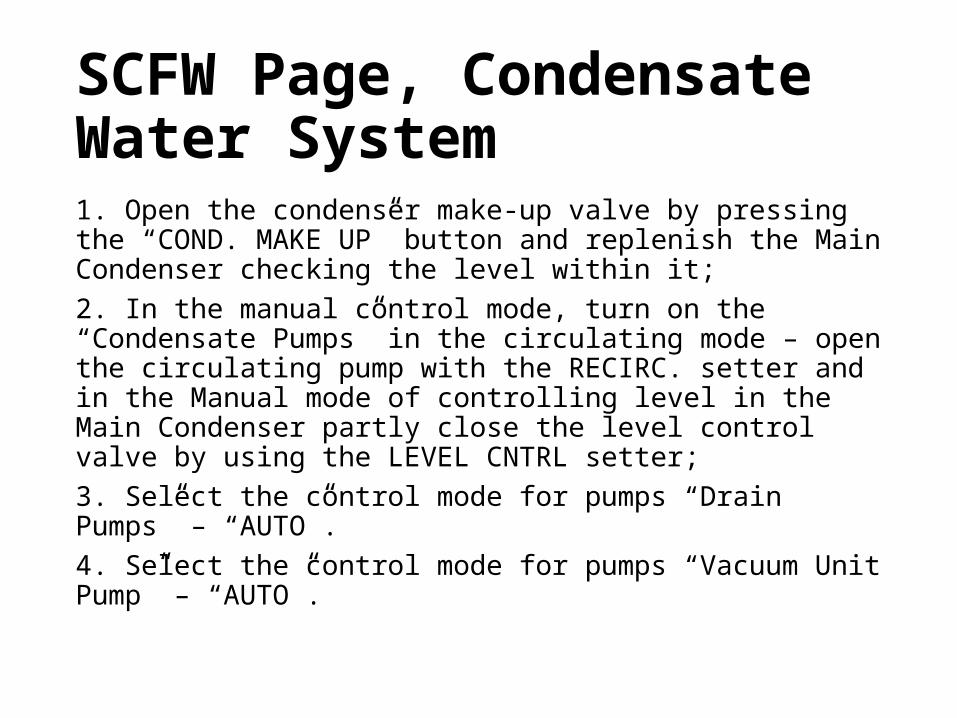
SCFW Page, Condensate Water System1. Open the condenser make-up valve by pressing the “COND. MAKE UP” button and replenish the Main Condenser checking the level within it;2. In the manual control mode, turn on the “Condensate Pumps” in the circulating mode – open the circulating pump with the RECIRC. setter and in the Manual mode of controlling level in the Main Condenser partly close the level control valve by using the LEVEL CNTRL setter;3. Select the control mode for pumps “Drain Pumps” – “AUTO”.4. Select the control mode for pumps “Vacuum Unit Pump” – “AUTO”.

MB Page, Fuel Oil, Gas & Atomizing1. Open the valves for supplying fuel oil and air for the fuel oil atomising by pressing the “MASTER FO” and “ATOMIZ. AIR” buttons.2. Turn on Leak Gas Fans 1 and 2;3. In the FO RECIRC. CONTROL group select the Manual control mode and open slightly the fuel oil recirculation valve by using the FO RECIRC. setter, thus ensuring the low fuel oil pressure;4. Turn on the FDF fan – in the FDF CONTROL group press the “START” button;5. Open the fuel oil supply valve – press the “FO SHUT OFF” button;6. Turn on the Seal Fan – press the “START/STOP” button;7. In the BURNERS CONTROL group, select the Manual burners control mode and turn on fuel oil burner 1 by pressing the “FO” button;

MB Page, Steam & Water System1. In the REMOTE MODE group, switch the boiler control to the Auto mode;2. In the STEAM UP PROGRAM group, run the steam-up program – press the “REQUEST” button: the “IN PROGRESS” program operation indicator should light up.Control of the fuel oil flow is in accordance with the temporal program of pressure build-up in the boiler Steam Drum.

Further operations1. After the start of the steam rising in the boiler, on the “Desuperheated Steam & Dump System” panel, press the “MB 1(2) DSH STEAM” button – open the valve for letting out the desuperheated steam from the boiler.2. Put the turbine sealing system into operation (the “Gland System” panel).3. Starting from the steam overpressure in the order of 1.5–2 bars (the arrow on the mnemonic diagram will turn from blue to orange) you can close the boiler AIR BLOW valve (the BLOW OFF VALVES group on the “Steam & Water System” panel).

4. The fuel Atomizing Steam instead of the compressed air is used starting from the desuperheated steam pressure of 8 bars.5. In the BLOW OFF VALVES group of the “Steam & Water System” panel, close the blow-off valve of the SUPER HEATER.6. As the pressure grows to 10 bars in the boiler “Steam Drum”, turn on the fuel oil preheating and switch to the heavy fuel oil by increasing its supply pressure with the aid of the recirculation valve;7. As the pressure reaches 15 bars in the boiler “Steam Drum”, open the valve forletting out the superheated steam from the boiler – the “MB 1(2) SH STEAM OUT V.” button on the “Superheated Steam System” panel;8. With the lowering of the water level in the boiler steam drum, in the BLOW OFF VALVES group of the “Steam & Water System”, close the blow-off Drum Blow valve of the steam drum.9. Run the turbo-driven feed water pump of boiler 1 (2).10. Supply steam to the turbo generator 1 by pressing the “TG1” panel on the “Superheated Steam System” panel;