Embed Size (px)
Citation preview
1
A
Training Report on
“BSNL(Telecom) ” In
(Telecom District manager ,shahjahanpur) Submitted in the partial fulfillment of the requirement of degree of
BACHELOR OF TECHNOLOGY
in Electronics & Communication Engg.
By PRAVEEN KUMAR PAL
( 11071035 )
DEPARTMENT OF ELECTRONIC & COMMUNICATION
SCHOOL OF ENGINEERING & TECHNOLOGY
IFTM UNIVERSITY MORADABAD
Session: 2014-15
2
INTRODUCTION
All industries operate in a specific environment which keeps changing and the firms in the
business need to understand it to dynamically adjust their actions for best results. Like
minded firms get together to form associations in order to protect their common interests.
Other stake holders also develop a system to take care of their issues. Governments also need
to intervene for ensuring fair competition and the best value for money for its citizens. This
handout gives exposure on the Telecom Environment in India and also dwells on the role of
international bodies in standardizing and promoting Telecom Growth in the world.
The Indian postal and telecom sectors saw a slow and uneasy start. In 1850, the first
experimental electric telegraph line was started between and . In 1851, it was opened for the
use of. The Posts and Telegraphs department occupied a small corner of the Public Works
Department, at that time.
Subsequently, the construction of 4,000 miles (6,400 km) of telegraph lines connecting
Kolkata (then Calcutta) and Peshawar in the north along with Agra, (then Bombay) through
Sindwa Ghats, and well as and was started in November 1853. , who pioneered the and in
India, belonged to the Public Works Department, and worked towards the development of
telecom throughout this period. A separate department was opened in 1854 when telegraph
facilities were opened to the public.
In 1880, two namely The Ltd. and The Anglo-Indian Telephone Company Ltd.
approached to establish the permission was refused on the grounds that the establishment of
telephones was a Government monopoly and that the Government itself would undertake the
work. In 1881, the Government later reversed its earlier decision and a licence was granted to
the Limited of for opening telephone exchanges at ,and and the first formal telephone service
was established in the country. On the 28th January 1882, Major E. Baring, Member of the 's
Council declared open the Telephone Exchanges in Calcutta, Bombay and Madras. The
exchange in Calcutta named the "Central Exchange", was opened at third floor of the
building at 7, Council House Street, with a total of 93 subscribers. Later that year, Bombay
also witnessed the opening of a telephone exchange.
ABOUT THE EXCHANGE
In the field of , a telephone exchange or telephone switch is a system of electronic
components that connects telephone calls. A central office is the physical building used to
3
house equipment including telephone switches, which make "work" in the sense of making
connections and relaying the speech information
TYPE’S OF EXCHANGE
Manual exchange
Strowger exchange
Cross bar exchange
Electronics exchange (analog and digital exchange)
MANUAL EXCAHNGE
With manual service, the customer lifts the receiver off-hook and asks the operator to connect
the call to a requested number. Provided that the number is in the same central office, the
operator connects the call by plugging into the jack on the switchboard corresponding to the
called customer's line. If the call is to another central office, the operator plugs into the trunk
for the other office and asks the operator answering (known as the "inward" operator) to
connect the call.
STROWGER EXCHANGE
Strowger developed a system of automatic switching using an electromechanical switch
based around electromagnets and pawls. With the help of his nephew (Walter S. Strowger) he
produced a working model in 1888 .selector starts in the 'home' position and with each
'impulse' the wiper contacts would progress round the output bank to the next position. Each
output would be connected to a different subscriber, thus the caller could connect to any other
subscriber who was connected to that bank, without any manual assistance from an operator.
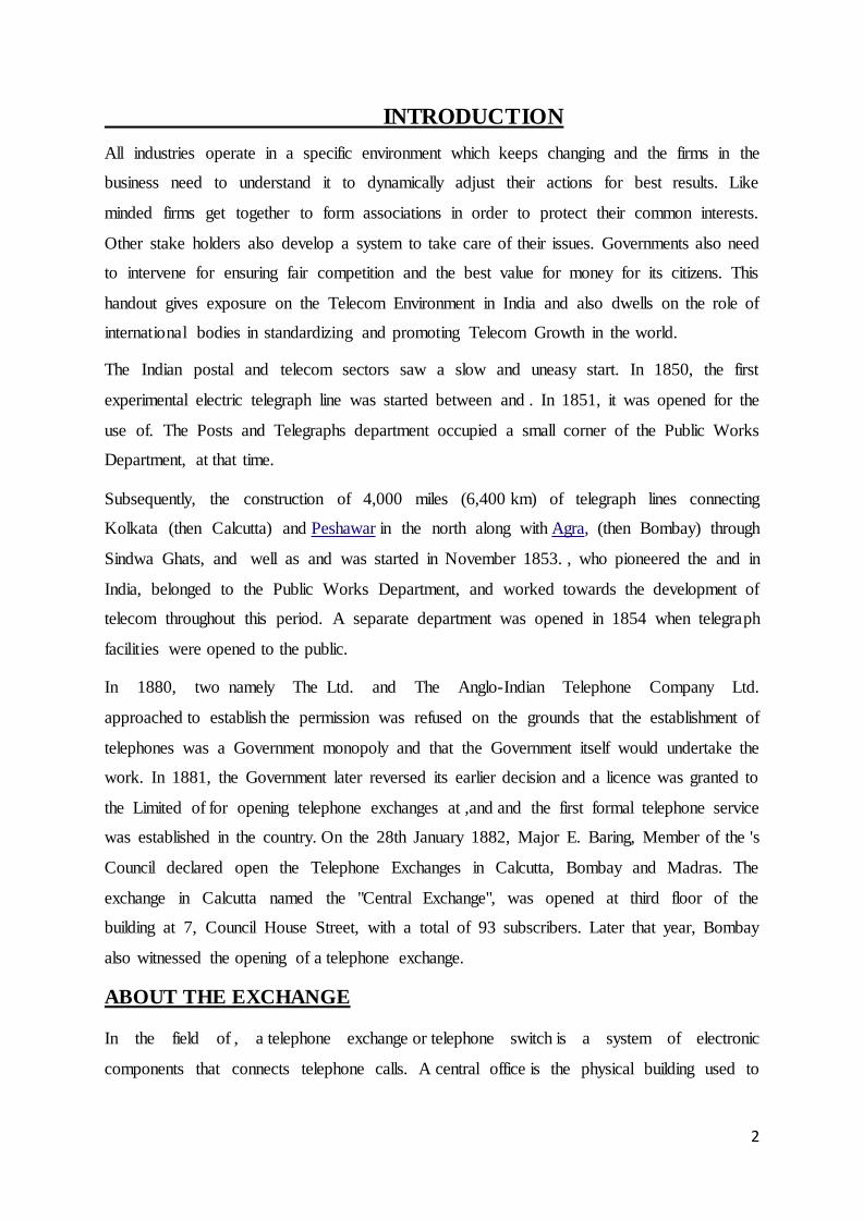
Diagram of a simple Selector(1.0)
In Figure 2 (above), the selector has 10 outputs, so a caller can choose to connect to any of 10
different subscribers by dialing any digit from 1 to 0 (0=10). This sort of automatic selector is
known as a Uni-selector, as it moves in just one plane (rotary).By mounting several arcs of
4
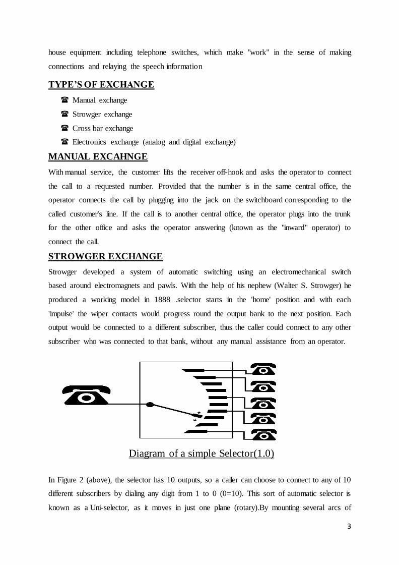
outlets on top of each other, the number of outlets can be increased significantly but the
wipers are then required to move both horizontally to select a bank and then vertically to
move around that bank to the required outlet. Such a selector is known as a Two-Motion
Selector. Two-motion selectors typically have 10 rows of 10 outlets, thus 100 possible outlets
altogether. A two-motion selector can therefore accept two dialed digits from a subscriber
and route the call to any of 100 numbers. The selector 'wipers' always start in their resting
'home' position. The first digit moves the selector vertically up to the corresponding level and
then the second digit moves the wipers around the contacts of that level. This is shown in
figure 3, below.
A Two-Motion "Final" Selector(1.1)
The type of selector shown above is known as a Final Selector as it takes the final two digits
of the number dialed. Most numbers dialed are several digits longer, and therefore pass
through a chain of selectors. Selectors previous to the Final Selectors are different; they are
called Group Selectors. Group selectors take only ONE digit from the caller, and step up the
number of levels according to the digit dialed. The rotary movement is then automatic; the
wipers search around that level to find a free outlet - i.e. the next free selector in the chain.
This is covered in more depth later.
CROSS BAR EXCAHNG In a crossbar switch (also known as cross-point
switch, cross point switch, or matrix switch) is a connecting multiple inputs to multiple
outputs in a matrix manner. Originally the term was used literally, for a matrix switch
controlled by a grid of crossing . A crossbar switch is an assembly of individual switches
between multiple inputs and multiple outputs. The switches are arranged in a matrix. If the
crossbar switch has M inputs and N outputs, then a crossbar has a matrix with M x N cross-
5
points or places where the "bars" cross. At each cross point is a switch; when closed, it
connects one of M inputs to one of N outputs. A given crossbar is a single layer, non-
blocking switch. Collections of crossbars can be used to implement multiple layer and/or
blocking switches. A crossbar switching system is also called a co-ordinate switching system.
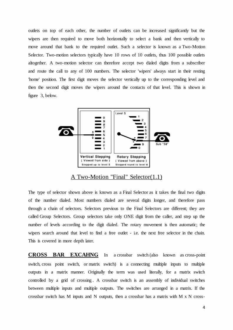
ELECTRONICS EXCHANGE
It is based on the automatic control by stored programmed in computer linked to it. It cover
all the main drawbacks of above mentioned exchange. It may be digital or analog but mostly
digital electronics exchanges are now common. It base on the principal time division
switching or space division switching. Space division switching is used for analog electronics
exchange and time division switching is used for digital exchange.
Fig(1.3)
Space Division switching System
In a space Division Switching system, a continuous physical path is set up between input and
output terminations. This path is separate for each connection and is held for the entire
duration of the call. Path for different connections is independent of each other. Once a
continuous path has been established., Signals are interchanged between the two
terminations. Such a switching network can employ either metallic or electronic cross points.
Previously, usage of metallic cross-points using reed relays and all were favored. They have
the advantage of compatibility with the existing line and trunk signaling conditions in the
network.
6
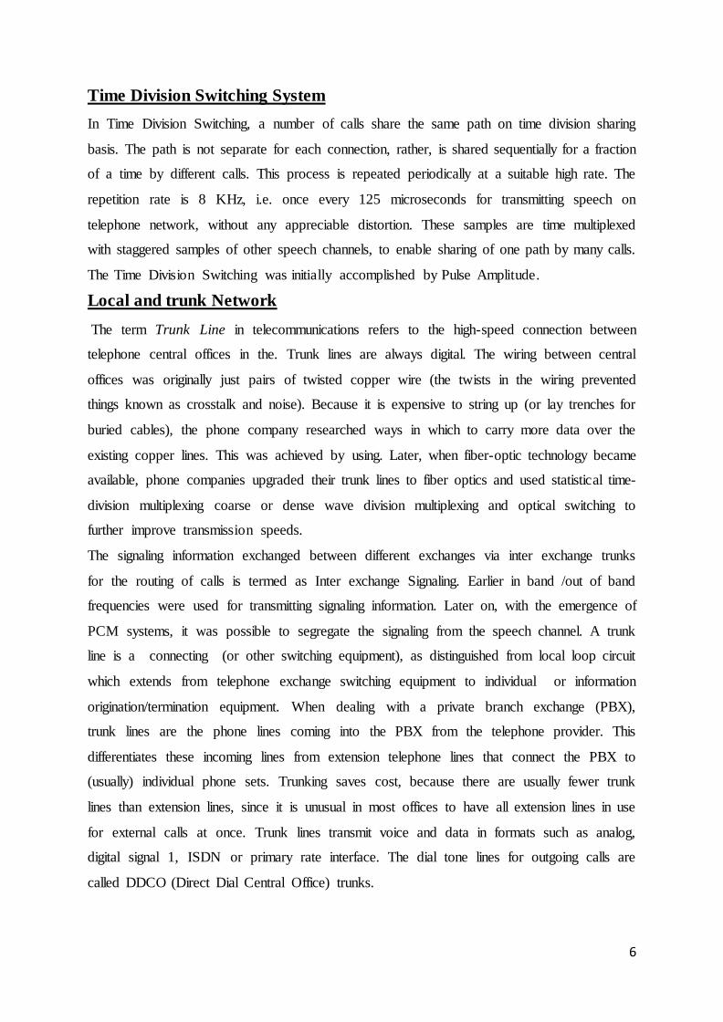
Time Division Switching System
In Time Division Switching, a number of calls share the same path on time division sharing
basis. The path is not separate for each connection, rather, is shared sequentially for a fraction
of a time by different calls. This process is repeated periodically at a suitable high rate. The
repetition rate is 8 KHz, i.e. once every 125 microseconds for transmitting speech on
telephone network, without any appreciable distortion. These samples are time multiplexed
with staggered samples of other speech channels, to enable sharing of one path by many calls.
The Time Division Switching was initially accomplished by Pulse Amplitude.
Local and trunk Network
The term Trunk Line in telecommunications refers to the high-speed connection between
telephone central offices in the. Trunk lines are always digital. The wiring between central
offices was originally just pairs of twisted copper wire (the twists in the wiring prevented
things known as crosstalk and noise). Because it is expensive to string up (or lay trenches for
buried cables), the phone company researched ways in which to carry more data over the
existing copper lines. This was achieved by using. Later, when fiber-optic technology became
available, phone companies upgraded their trunk lines to fiber optics and used statistical time-
division multiplexing coarse or dense wave division multiplexing and optical switching to
further improve transmission speeds.
The signaling information exchanged between different exchanges via inter exchange trunks
for the routing of calls is termed as Inter exchange Signaling. Earlier in band /out of band
frequencies were used for transmitting signaling information. Later on, with the emergence of
PCM systems, it was possible to segregate the signaling from the speech channel. A trunk
line is a connecting (or other switching equipment), as distinguished from local loop circuit
which extends from telephone exchange switching equipment to individual or information
origination/termination equipment. When dealing with a private branch exchange (PBX),
trunk lines are the phone lines coming into the PBX from the telephone provider. This
differentiates these incoming lines from extension telephone lines that connect the PBX to
(usually) individual phone sets. Trunking saves cost, because there are usually fewer trunk
lines than extension lines, since it is unusual in most offices to have all extension lines in use
for external calls at once. Trunk lines transmit voice and data in formats such as analog,
digital signal 1, ISDN or primary rate interface. The dial tone lines for outgoing calls are
called DDCO (Direct Dial Central Office) trunks.
7
A travelling over a trunk line is not actually flowing any faster. The electrical signal on a
voice line takes the same amount of time to traverse the wire as a similar length trunk line.
What makes trunk lines faster is that the has been altered to carry more data in less time using
more advanced multiplexing and techniques. If you compared a voice line and a trunk line
and put them side by side and observed them, the first pieces of information arrive
simultaneously on both the voice and trunk line. However, the last piece of information
would arrive sooner on the trunk line. No matter what, you can't break the laws of physics.
Electricity over copper or laser light over fiber optics, you cannot break the speed of light--
though that has rarely stopped uneducated IT or IS managers from demanding that cabling
perform faster instead of upgrading equipment.
Trunk lines can contain thousands of simultaneous calls that have been combined using.
These thousands of calls are carried from one central office to another where they can be
connected to a de-multiplexing device and switched through digital access cross connecting
switches to reach the proper exchange and local phone number.
Trunking
In telecommunications systems, trunking is the aggregation of multiple user circuits into a
single channel. The aggregation is achieved using some form of multiplexing.
PCM
A long distance or local telephone conversation between two persons could be
provided by using a pair of open wire lines or underground cable as early as mid of
19th century. However, due to fast industrial development and an increased telephone
awareness, demand for trunk and local traffic went on increasing at a rapid rate. To
cater to the increased demand of traffic between two stations or between two
subscribers at the same station we resorted to the use of an increased number of
pairs on either the open wire alignment, or in underground cable. This could solve
the problem for some time only as there is a limit to the number of open wire pairs
that can be installed on one alignment due to headway consideration and maintenance
problems. Similarly increasing the number of open wire pairs that can be installed on
one alignment due to headway consideration and maintenance problems. Similarly
increasing the number of pairs to the underground cable is uneconomical and leads
to maintenance problems.
It, therefore became imperative to think of new technical innovations which could exploit the
available bandwidth of transmission media such as open wire lines or underground cables to
8
provide more number of circuits on one pair. The technique used to provide a number of
circuits using a single transmission link is called Multiplexing.
Basic Requirements for PCM System:
To develop a PCM signal from several analogue signals, the following processing steps are
required:
1. Filtering
2. Sampling
3. Quantisation
4. Encoding
5. Line Coding
Duplexing Methodology:
Duplexing is the technique by which the send and receive paths are separated over the
medium, since transmission entities (modulator, amplifiers, demodulators) are involved.
There are two types of Duplexing:
1. Frequency Division Duplexing (FDD)
2. Time Division Duplexing (TDD)
Frequency Division Duplexing (FDD):
Different frequencies are used for send and receive paths and hence there will be a forward
band and reverse band. Duplexer is needed if simultaneous transmission (send) and reception
(receive) methodology is adopted. Frequency separation between forward band and reverse
band is constant.
Time Division Duplexing (TDD):
TDD uses different time slots for transmission and reception paths. Single radio frequency
can be used in both the directions instead of two as in FDD. No duplexer is required. Only a
fast switching synthesizer, RF filter path and fast antenna switch are needed. It increases the
battery life of mobile phones.
9
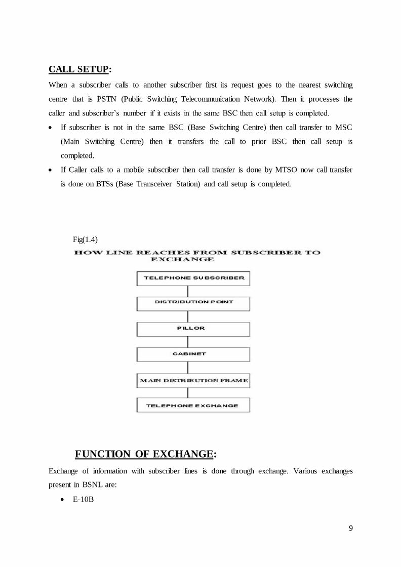
CALL SETUP:
When a subscriber calls to another subscriber first its request goes to the nearest switching
centre that is PSTN (Public Switching Telecommunication Network). Then it processes the
caller and subscriber’s number if it exists in the same BSC then call setup is completed.
If subscriber is not in the same BSC (Base Switching Centre) then call transfer to MSC
(Main Switching Centre) then it transfers the call to prior BSC then call setup is
completed.
If Caller calls to a mobile subscriber then call transfer is done by MTSO now call transfer
is done on BTSs (Base Transceiver Station) and call setup is completed.
Fig(1.4)
FUNCTION OF EXCHANGE:
Exchange of information with subscriber lines is done through exchange. Various exchanges
present in BSNL are:
E-10B
10
OCB283
EWSD
CDOT
All exchange has some purposes and some basic structural units, which are:
1. subscribers connection unit
2. switching network (CX)
3. control unit
4. OMC
ELECTRONICSEXCHANGE
It is based on the automatic control by stored programmed in computer linked to it. It cover
all the main drawbacks of above mentioned exchange. It may be digital or analog but mostly
digital electronics exchanges are now common. It base on the principal time division
switching or space division switching. Space division switching is used for analog electronics
exchange and time division switching is used for digital exchange.
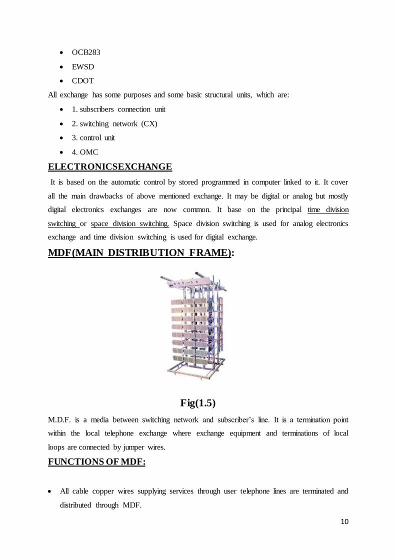
MDF(MAIN DISTRIBUTION FRAME):
Fig(1.5)
M.D.F. is a media between switching network and subscriber’s line. It is a termination point
within the local telephone exchange where exchange equipment and terminations of local
loops are connected by jumper wires.
FUNCTIONS OF MDF:
All cable copper wires supplying services through user telephone lines are terminated and
distributed through MDF.
11
The most common kind of large MDF is a long steel rack accessible from both sides.
Each jumper is a twisted wire.
It consists of local connection and broadband connection frames for the main Exchange
area.
The MDF usually holds central office protective devices including heat coils and
functions as a test point between a line and the office.
It provides testing of calls.
It checks whether fault is indoor or external.
PARTS OF THE MDF
Horizontal side
Vertical side
HORIZONTAL SIDE:
It is again subdivided in to two part
Exchange side Line side
RACK: - On the rack, the tags are situated. One rack is having eight tags. The courting is
done from up (0) to down (7).
TAG: - Each rack consists of eight tags.
1 tag = 4 core
1 core = 4 bunch
1 bunch = 2 line
Vertical side is again subdivided in two parts:
One part is connected with the horizontal side and another with the subscriber line by using
100 pair underground cable.
SVERTICAL SIDE:
The vertical aside connected to the underground cable. This cable is having 100 pairs.
These pair is distributed when we allot the telephone number to the subscriber.
POWER PLANT
It consists of a online U.P.S. (Uninterruptable Power Supply).
It provides -48V to the switch rooms and 48V to the connections.
12
Batteries are artificially discharged once in a year for their maintenance.
Cooling is provided through fans & AC.
There is earth region too for protection.
CENTRAL AIR CONDITIONER
For the function of electrical equipment, cooling system is basic requirement. The basic
advantages of cooling systems are to cool the exchange and to maintain the thermal stability
of the exchange.
VARIOUS INTERNET SERVICES
LEASED LINES
The information sent through the leased line travels along dedicated secure channels,
eliminating the congestion that occurs in shared networks.
between two points set up by a telecommunications carrier. They can be used for telephone,
data, or Internet services
A leasedline (dedicated line) is a permanent fiber optic or telephone connection.
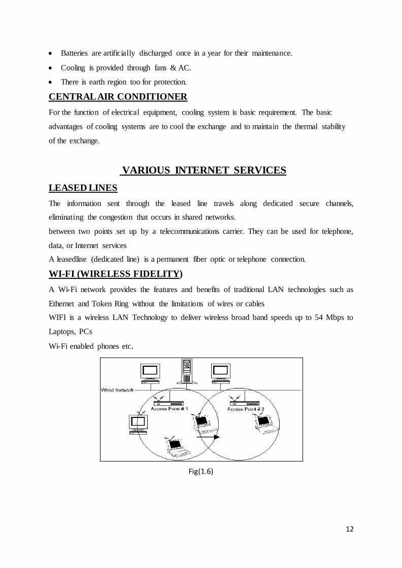
WI-FI (WIRELESS FIDELITY)
A Wi-Fi network provides the features and benefits of traditional LAN technologies such as
Ethernet and Token Ring without the limitations of wires or cables
WIFI is a wireless LAN Technology to deliver wireless broad band speeds up to 54 Mbps to
Laptops, PCs
Wi-Fi enabled phones etc.
Fig(1.6)
13
BSNL Broadband Service
Broadband refers to a connection that has capacity to transmit large amount of data speed.
Presently a connection having download speeds of 256 kbps or more is classified as
broadband. When connected to the Internet broadband connection allows surfing or
downloading much faster than a dial-up or any other narrowband connections. BSNL offers 2
Mbps minimum download speed for its Broadband connections.Requirement for providing
Broad Band connection
Personal Computer
ADSL Modem
Land Line Connection
Splitter for separating telephone from Personal computer
High speed Internet Access: This is the always-on Internet access service with speed
ranging from 256 kbps to 8 Mbps.
WIMAX
WI-MAX is an acronym that stands for World- wide Interoperability for Microwave
Access and thistechnology is designed to accommodate both fixed and mobile broadband
applications
SALIENT FEATURES OF WIMAX:
OFDM-based physical layer.
Very high peak data rates.
Adaptive modulation and coding (AMC)
Support for TDD and FDD OFDMA.
Flexible and dynamic per user resource allocation.
Support for mobility.
IP-based architecture.
14
FTTH
FTTH is an acronym which stands for Fiber To The Home .In this technology an optical
fiber of desired bandwidth and frequency is connected to the local residence of the user
to provide high speed internet facility up togbps.This facility is first launched by BSNL
in India.
OSI NETWORKING MODEL
The open systems interconnection model defines all the methods and protocols needed to
connect one computer to any other over a network .It consists of following seven layers:
Physical Layer:
The physical layer defines the properties of the physical medium used to make a network
connection
Data Link Layer:
The data link layer, layer 2, defines standard that assign meaning to the bits carried by the
physical layer
Network Layer:
The network layer, Layer-3, is where a lot of action goes on for most networks.
Transport Layer:
The Transport Layer, layer-4, manages the flow of information from one network node to
another.
Session layer:
The session layer, layer-5, defines the connection from a user to a network server, or from a
peer on a network to another peer
Presentation Layer:
The presentation layer, layer-6, takes the data supplied by the lower level layer and transform
so it can be presented to the system
Application Layer:
15
The Application layer, layer 7, controls how the operating system and its application interact
with network.
FIBER OPTIC TRANSMISSION SYSTEM
FIBER OPTICS:
The use and demand for optical fiber has grown tremendously and optical-fiber applications
are numerous. Telecommunication applications are widespread, ranging from global
networks to desktop computers. These involve the transmission of voice, data, or video over
distances of less than a meter to hundreds of kilometers, using one of a few standard fiber
designs in one of several cable designs.
Another important application for optical fiber is the biomedical industry. Fiber-optic systems
are used in most modern telemedicine devices for transmission of digital diagnostic images.
Other applications for optical fiber include space, military, automotive, and the industrial
sector
The high bandwidth provided by fiber makes it the perfect choice for transmitting broadband
signals, such as high-definition television (HDTV) telecasts.
Optical fiber is also used extensively for transmission of data. Multinational firms need
secure, reliable systems to transfer data and financial information.
ADVANTAGES OF FIBRE OPTICS
Fiber Optics has the following advantages
• SPEED: Fiber optic networks operate at high speeds - up into the gigabits
• BANDWIDTH: large carrying capacity
• DISTANCE: Signals can be transmitted further without needing to be "refreshed" or
strengthened.
• RESISTANCE: Greater resistance to electromagnetic noise such as radios, motors or
other nearby cables.
• MAINTENANCE: Fiber optic cables costs much less to maint
CLASSIFICATION
There are three types of fibers:
16
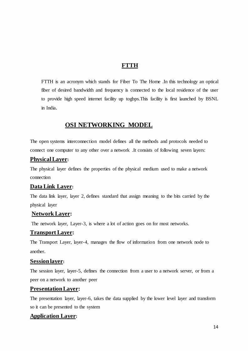
1.STEP-INDEX MULTIMODE FIBER: It has a large core, up to 100 microns in
diameter.
This type of fiber is best suited for transmission over short distances, in an endoscope.
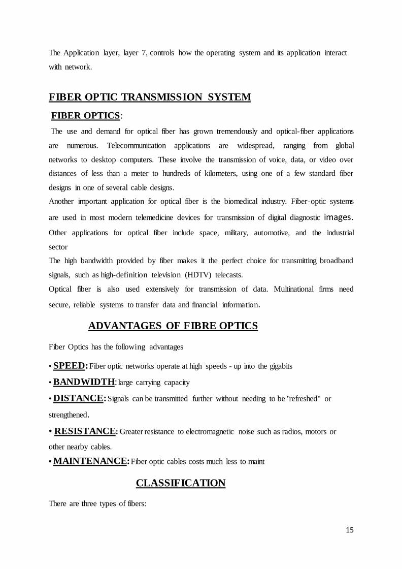
2. GRADED-INDEX MULTIMODE FIBER: It contains a core in which the refractive
index diminishes gradually from the center axis out toward the cladding.
3. SINGLE-MODE FIBER: It has a narrow core (eight microns or less), and the index
of refraction between the core and the cladding changes less than it does for multimode fibers
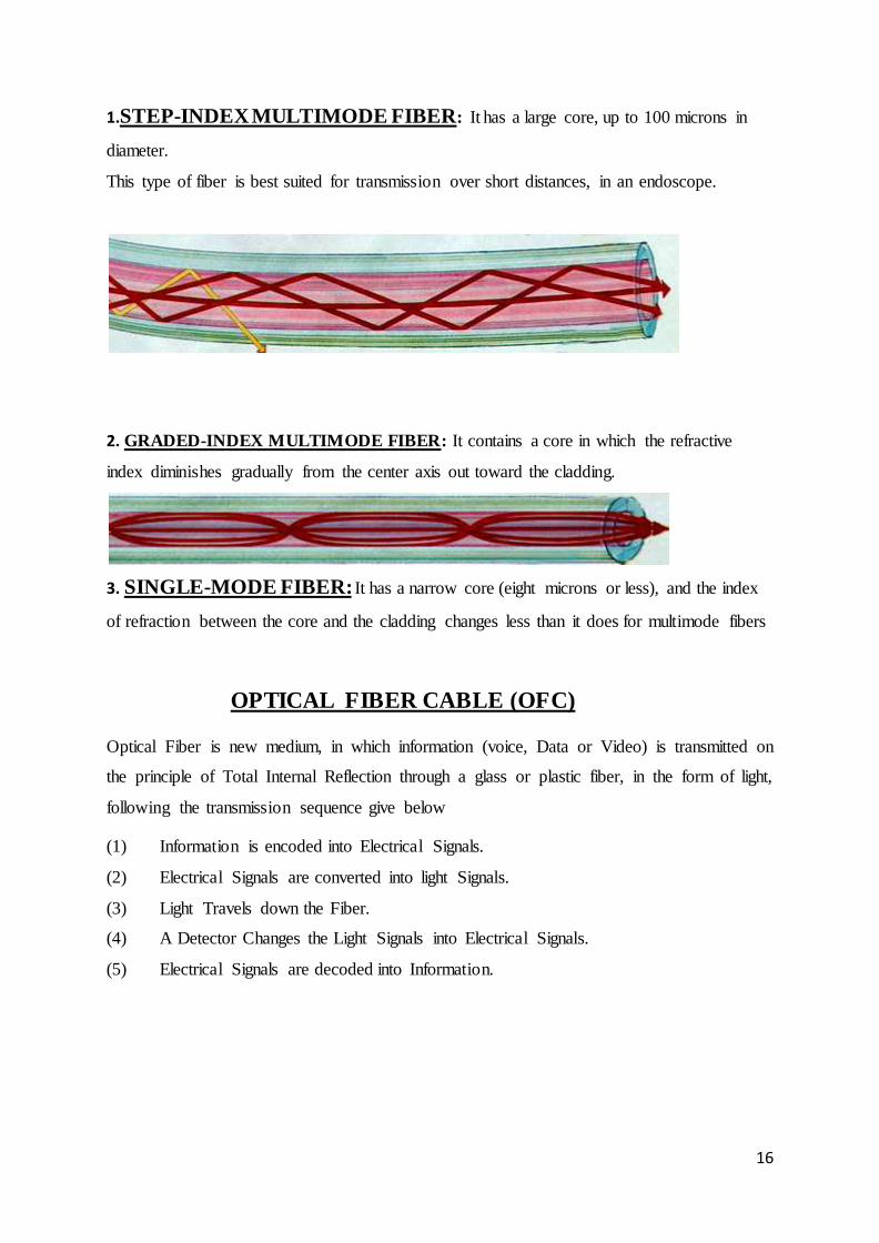
OPTICAL FIBER CABLE (OFC)
Optical Fiber is new medium, in which information (voice, Data or Video) is transmitted on
the principle of Total Internal Reflection through a glass or plastic fiber, in the form of light,
following the transmission sequence give below
(1) Information is encoded into Electrical Signals.
(2) Electrical Signals are converted into light Signals.
(3) Light Travels down the Fiber.
(4) A Detector Changes the Light Signals into Electrical Signals.
(5) Electrical Signals are decoded into Information.
17
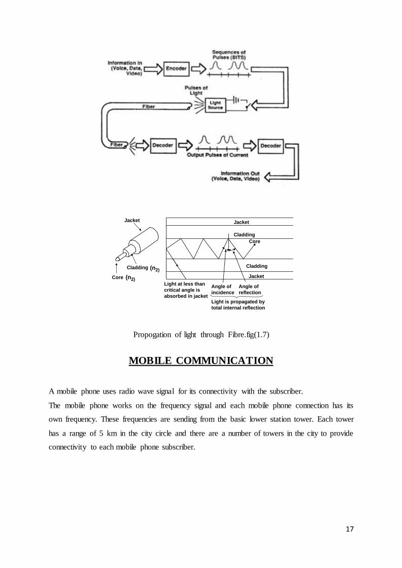
Propogation of light through Fibre.fig(1.7)
MOBILE COMMUNICATION
A mobile phone uses radio wave signal for its connectivity with the subscriber.
The mobile phone works on the frequency signal and each mobile phone connection has its
own frequency. These frequencies are sending from the basic lower station tower. Each tower
has a range of 5 km in the city circle and there are a number of towers in the city to provide
connectivity to each mobile phone subscriber.
Jacket
Cladding
Core
Cladding
Angle of
reflection
Angle of
incidence
Light at less than
critical angle is
absorbed in jacket
Jacket
Light is propagated by
total internal reflection
Jacket
Cladding
Core
(n2)
(n2)
Fig. Total Internal Reflection in an optical Fibre
18
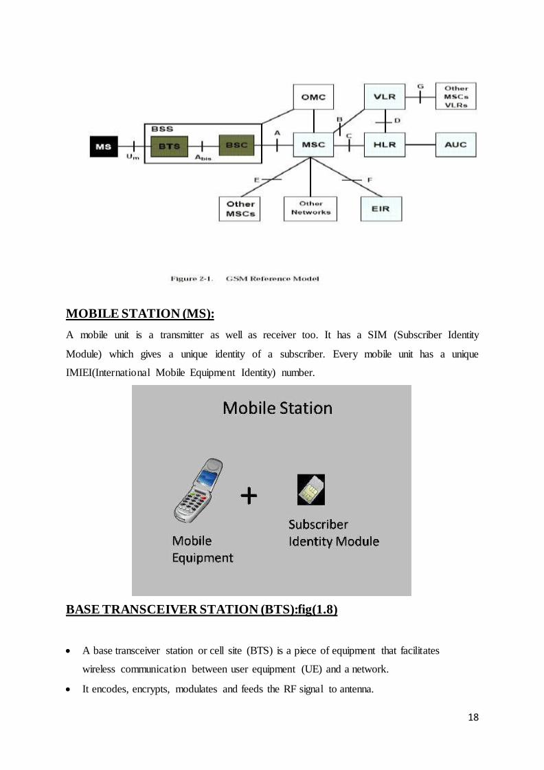
MOBILE STATION (MS):
A mobile unit is a transmitter as well as receiver too. It has a SIM (Subscriber Identity
Module) which gives a unique identity of a subscriber. Every mobile unit has a unique
IMIEI(International Mobile Equipment Identity) number.
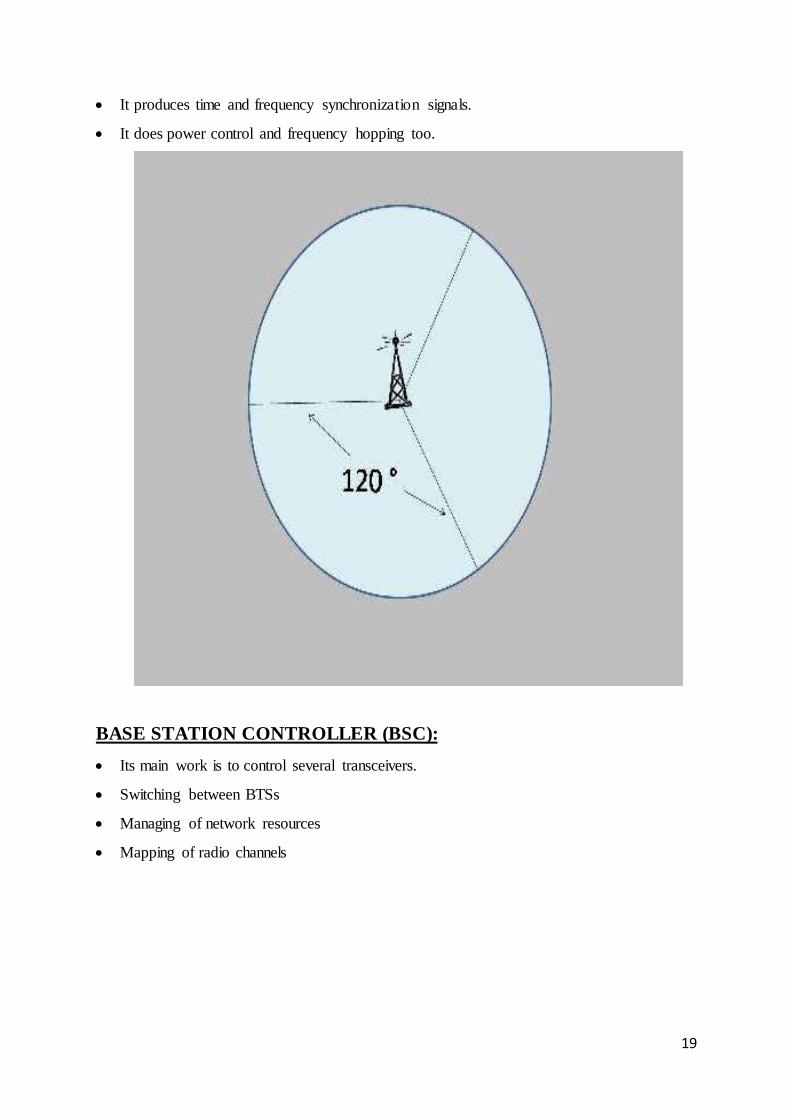
BASE TRANSCEIVER STATION (BTS):fig(1.8)
A base transceiver station or cell site (BTS) is a piece of equipment that facilitates
wireless communication between user equipment (UE) and a network.
It encodes, encrypts, modulates and feeds the RF signal to antenna.
19
It produces time and frequency synchronization signals.
It does power control and frequency hopping too.
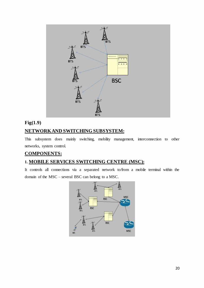
BASE STATION CONTROLLER (BSC):
Its main work is to control several transceivers.
Switching between BTSs
Managing of network resources
Mapping of radio channels
20
Fig(1.9)
NETWORK AND SWITCHING SUBSYSTEM:
This subsystem does mainly switching, mobility management, interconnection to other
networks, system control.
COMPONENTS:
1. MOBILE SERVICES SWITCHING CENTRE (MSC):
It controls all connections via a separated network to/from a mobile terminal within the
domain of the MSC – several BSC can belong to a MSC.
21
FUNCTION OF MOBILE SWITCHING CENTER (MSC):
Manages communication between GSM and other network (PSTN, Data Network and
GPRS).
Call setup basic switching, call handling.
Billing for subscriber.
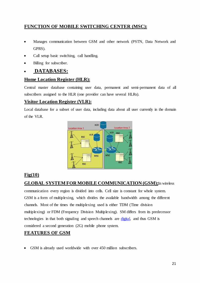
DATABASES:
Home Location Register (HLR):
Central master database containing user data, permanent and semi-permanent data of all
subscribers assigned to the HLR (one provider can have several HLRs).
Visitor Location Register (VLR):
Local database for a subset of user data, including data about all user currently in the domain
of the VLR.
Fig(10)
GLOBAL SYSTEM FOR MOBILE COMMUNICATION (GSM);In wireless
communication every region is divided into cells. Cell size is constant for whole system.
GSM is a form of multiplexing, which divides the available bandwidth among the different
channels. Most of the times the multiplexing used is either TDM (Time division
multiplexing) or FDM (Frequency Division Multiplexing). SM differs from its predecessor
technologies in that both signaling and speech channels are digital, and thus GSM is
considered a second generation (2G) mobile phone system.
FEATURES OF GSM
GSM is already used worldwide with over 450 million subscribers.
22
The availability of Subscriber Identity Modules, which are smart cards that provide secure
data encryption give GSM m-commerce advantages.
GENERAL PACKET RADIO SERVICE (GPRS)
General packet radio service (GPRS) is a packet oriented mobile data service available to
users of the 2G cellular communication systems, global system for mobile communications
(GSM), as well as in the 3G systems. In 2G systems, GPRS provides data rates of 56-114
kbps
GPRS extends the GSM circuit switched data capabilities and makes the following services
possible:
“Always on” Internet access
Multimedia messaging service (MMS)
Push to talk over cellular (PoC/PTT)
Point to Point (P2P) service: inter-networking with the internet (IP).
Increase message sending speed 30 messages per minute approximately.
CODE DIVISION MULTIPLE ACCESS (CDMA)
Code Division Multiple Access (CDMA) consistently provides better capacity for voice and
data communications that other commercial mobile technologies, allowing more subscribers
to connect at any given time, and it is the common platform on which 3G technologies are
built.
CDMA is a spread spectrum technology, allowing many users to occupy the same time and
frequency allocations in a given band/space
ADVANTAGES OF CDMA
Increased cellular communications security
Simultaneous conversations
Low power requirements and little cell-to-cell coordination needed by operators.
Extended reach-beneficial to rural users situated far from cells.
DIFFERENCE BETWEEN CDMA AND GSM:
The GSM stands for global system for mobile communication and CDMA for code
division multiple accesses.
GSM is a form of multiplexing, which divides the available bandwidth among the
different channels. Most of the times the multiplexing used are either TDM (Time
23
Division Multiplexing) or FDM (Frequency Division Multiplexing). On the other
hand CDMA is a type of multiple access scheme (which means allotting the given
bandwidth to multiple users) and makes use of spread spectrum technique which is
essentially increasing the size of spectrum.
FDMA (Frequency Division Multiple Access):Where individual transmission
separated by each other by the time.
WIRELESS IN LOCAL LOOP (WLL) MOBILE:
WLL is a communication system that connects customers to the Public Switch Telephone
Network (PSTN) using radio frequency signals as substitutes of conventional wires for all
part of connection between the subscribers and the telephone exchange. It works on CDMA
technique.
There is no standard for this so far. However, a number of national and international air
interface standards for digital cellular mobile telephone system are available.
CONCLUSION
The working in the project was an interesting and an all together learning experience. New
technologies, new progress and new competition are the order of the day. The core area to
look for is highly fragmented and information intense activity sequence that involves a
number of player and audiences.
The project mainly revolves around: EWSD, TAX, internet node, mobile communication,
WLL and intelligence network.
The emphasis of the different parts of the project is to throw light on the systems working in
Patna Main Exchange. The project also deals with modern technologies attributes and the
scope of implementation of the same in Patna. The area under study was limited to Patna
Main Exchange.
The scope of the study is very vast and the topic under study deals with the volatile
technology world. After the study, suggestions and strategy has been formulated keeping in
view the limitations of the field.
Evolution of this technological world is occurring every minute. Thanks to telecom and web
technologies, countries are coming closer day by day
REFERENCES
1. Data Communication And Networking- Behrouz A.Foruzan
2. Wireless Communication and Networks-William Stallings

24

25