Embed Size (px)
Citation preview
Nanoscale
REVIEW
Cite this: Nanoscale, 2016, 8, 6921
Received 11th December 2015,Accepted 24th February 2016
DOI: 10.1039/c5nr08803h
www.rsc.org/nanoscale
Nanostructured conducting polymers for energyapplications: towards a sustainable platform
Srabanti Ghosh,*a Thandavarayan Maiyalaganb and Rajendra N. Basu*a
Recently, there has been tremendous progress in the field of nanodimensional conducting polymers with
the objective of tuning the intrinsic properties of the polymer and the potential to be efficient, biocompa-
tible, inexpensive, and solution processable. Compared with bulk conducting polymers, conducting
polymer nanostructures possess a high electrical conductivity, large surface area, short path length for
ion transport and superior electrochemical activity which make them suitable for energy storage and con-
version applications. The current status of polymer nanostructure fabrication and characterization is
reviewed in detail. The present review includes syntheses, a deeper understanding of the principles under-
lying the electronic behavior of size and shape tunable polymer nanostructures, characterization tools
and analysis of composites. Finally, a detailed discussion of their effectiveness and perspectives in energy
storage and solar light harvesting is presented. In brief, a broad overview on the synthesis and possible
applications of conducting polymer nanostructures in energy domains such as fuel cells, photocatalysis,
supercapacitors and rechargeable batteries is described.
1. Introduction
The concept of conducting polymers (CPs) emerged in recentdecades and continues to attract the scientific community.1,2
Research in this area is continuing to grow with the objectiveof tuning the intrinsic properties of nanodimensional CPs tooffer multiple functionalities. Hence, primarily driven by theopportunity to develop novel multifunctional materials on onehand, and sustainable technologies on the other, several suc-cessful approaches have been explored to develop conductingpolymer nanostructures (CPNs). Many excellent reviews regard-ing the development of CPs such as polyaniline, polymer filmelectrodes and their characterization have been published.3–7
Moreover, the sensing and device applications of CPs have alsobeen reviewed.8–11 However, the preparation, characterizationand application of CPNs in the energy domain are still at theforeground of research activity.12–14 Consequently, there is aneed for a deeper understanding of the availability of novelpolymer nanostructures, the development of models of thematerials’ behavior and technologies aimed at optimizing andimplementing their active function in applications. Specifi-cally, we present an overview of the different methods com-monly employed in the fabrication of CPNs and hybridcomposites. We also discuss the characterization of CPNs
using microscopy and other techniques as well as their appli-cation in the fields of energy storage and conversion, andelectrocatalysis.
The initial work on CPs was instigated by three Nobel laure-ates (A. J. Heeger, H. Shirakawa, and A. G. MacDiarmid).15,16
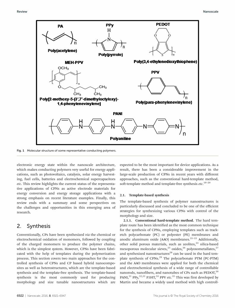
They discovered an increase of nearly 10 orders of magnitudein the electrical conductivity of polyacetylene (PA) when it wasdoped with iodine or other acceptors.17 As shown in Fig. 1,conducting polymers include polyacetylene (PA), polypyrrole(PPy), polyaniline (PANI), poly(3,4-ethylenedioxythiophene)(PEDOT) and poly(p-phenylenevinylene) (PPV) etc. Since then,CPs have received increasing attention in both fundamentalresearch and various application fields in recent decades.
Compared to bulk polymers, CPNs displayed superior per-formances for energy storage and conversion which is associ-ated with the nanoscale size giving a superior electricalconductivity, high surface area, high carrier mobility, improvedelectrochemical activity and good mechanical properties etc.Numerous synthetic strategies have been developed to obtainvarious conductive polymer nanostructures such as nano-particles (NPs), nanowires, nanofibers, and nanotubes etc.,and high-performance devices based on these nanostructuredpolymers have been realized.12–14
This review covers recent progress in the wet-chemicaldevelopment of conducting polymer nanostructures andhybrid strategies based on the functional associations of semi-conductors and metals via template synthesis routes, includ-ing soft and hard template methods. Controlling thedimensions of each component permits engineering of the
aCSIR - Central Glass and Ceramic Research Institute, 196, Raja S.C. Mullick Road,
Kolkata-700032, India. E-mail: [email protected], [email protected] of Chemistry, University of East Anglia, Norwich NR4 7TJ, UK
This journal is © The Royal Society of Chemistry 2016 Nanoscale, 2016, 8, 6921–6947 | 6921
electronic energy state within the nanoscale architecture,which makes conducting polymers very useful for energy appli-cations, such as photovoltaics, catalysis, solar energy harvest-ing, fuel cells, batteries and electrochemical supercapacitorsetc. This review highlights the current status of the representa-tive applications of CPNs as active electrode materials forenergy conversion and energy storage applications with astrong emphasis on recent literature examples. Finally, thisreview ends with a summary and some perspectives onthe challenges and opportunities in this emerging area ofresearch.
2. Synthesis
Conventionally, CPs have been synthesized via the chemical orelectrochemical oxidation of monomers, followed by couplingof the charged monomers to produce the polymer chains,which is the simplest system. However, CPNs have been fabri-cated with the help of templates during the polymerizationprocess. This section covers two main approaches for the con-trolled synthesis of CPNs and CP based hybrid nanocompo-sites as well as heterostructures, which are the template-basedsynthesis and the template-free synthesis. The template-basedsynthesis is the most commonly used for producingmorphology and size tunable nanostructures which are
expected to be the most important for device applications. As aresult, there has been a considerable improvement in thelarge-scale production of CPNs in recent years with differentapproaches, such as the conventional hard-template method,soft-template method and template-free synthesis etc.18–20
2.1. Template-based synthesis
The template-based synthesis of polymer nanostructures isparticularly discussed and concluded to be one of the efficientstrategies for synthesizing various CPNs with control of themorphology and size.
2.1.1. Conventional hard-template method. The hard tem-plate route has been identified as the most common techniquefor the synthesis of CPNs, employing templates such as track-etch polycarbonate (PC) or polyester (PE) membranes andanodic aluminum oxide (AAO) membranes.21–23 Additionally,other solid porous materials, such as zeolites,24 silica-basedmesoporous molecular sieves,25 oxides,26 polyoxometallates,27
and synthesized nanostructures28 can be used in the hard tem-plate synthesis of CPNs.29 The polycarbonate PTM (PC-PTM)and the AAO membranes were applied for both the chemicaland electrochemical synthesis of a wide range of controllablenanorods, nanofibers, and nanotubes of CPs such as PEDOT,30
PANI,31 PPy,32,33 P3HT,34 PPV etc.35 This was first developed byMartin and became a widely used method with high controll-
Fig. 1 Molecular structure of some representative conducting polymers.
Review Nanoscale
6922 | Nanoscale, 2016, 8, 6921–6947 This journal is © The Royal Society of Chemistry 2016
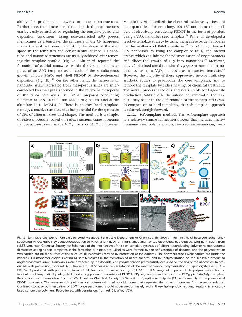
ability for producing nanowires or tube nanostructures.Furthermore, the dimensions of the deposited nanostructurescan be easily controlled by regulating the template pores anddeposition conditions. Using non-connected AAO porousmembranes as a template, the synthesis of the CP happenedinside the isolated pores, replicating the shape of the voidspace in the templates and consequently, aligned 1D nano-tube and nanowire structures are usually achieved after remov-ing the template scaffold (Fig. 2a). Liu et al. reported theformation of coaxial nanowires within the 200 nm diameterpores of an AAO template as a result of the simultaneousgrowth of core MnO2 and shell PEDOT by electrochemicaldeposition (Fig. 2b).36 On the other hand, the nanowire ornanotube arrays fabricated from mesoporous silica are inter-connected by small pillars formed in the micro- or mesoporesof the silica pore walls. Bein et al. prepared conductingfilaments of PANI in the 3 nm wide hexagonal channel of thealuminosilicate MCM-41.37 There is another hard template,namely, a reactive template that has potential for the synthesisof CPs of different sizes and shapes. The method is a simple,one-step procedure, based on redox reactions using inorganicnanostructures, such as the V2O5 fibers or MnO2 nanowires.
Manohar et al. described the chemical oxidative synthesis ofbulk quantities of micron long, 100–180 nm diameter nanofi-bers of electrically conducting PEDOT in the form of powdersusing a V2O5 nanofiber seed template.38 Pan et al. developed areactive template strategy by using manganese oxide nanowiresfor the synthesis of PANI nanotubes.39 Lu et al. synthesizedPPy nanotubes by using the complex of FeCl3 and methylorange which can initiate the polymerization of PPy monomersand direct the growth of PPy into nanotubes.40 Moreover,Li et al. obtained one-dimensional V2O5/PANI core–shell nano-belts by using a V2O5 nanobelt as a reactive template.41
However, the majority of these approaches involve multi-stepsynthetic routes to pre-modify the core templates, and toremove the template by either heating, or chemical treatment.The overall process is tedious and not suitable for large-scaleproduction. Additionally, the subsequent removal of the tem-plate may result in the deformation of the as-prepared CPNs.In comparison to hard templates, the soft template approachis relatively straightforward.
2.1.2. Soft-template method. The soft-template approachis a relatively simple fabrication process that includes micro-/mini-emulsion polymerization, reversed-microemulsion, layer-
Fig. 2 (a) Image courtsey of Ran Liu’s personal webpage, Penn State Department of Chemistry. (b) Growth mechanisms of heterogeneous nano-structured MnO2/PEDOT by coelectrodeposition of MnO2 and PEDOT on ring-shaped and flat-top electrodes. Reproduced, with permission, fromref.36, American Chemical Society. (c) Schematic of the mechanism of the soft-template synthesis of different conducting polymer nanostructures:(i) micelles acting as soft-templates in the formation of nanotubes. Micelles were formed by the self-assembly of dopants, and the polymerizationwas carried out on the surface of the micelles; (ii) nanowires formed by protection of the dopants. The polymerizations were carried out inside themicelles; (iii) monomer droplets acting as soft-templates in the formation of micro-spheres; and (iv) polymerization on the substrate producingaligned nanowire arrays. Nanowires were protected by the dopants, and polymerization preferentially occurred on the tips of the nanowires. Repro-duced, with permission, from ref. 48, Elsevier Ltd. (d) Schematic representation of the electrochemical polymerization of liquid crystalline EDOT–PDPPA. Reproduced, with permission, from ref. 64, American Chemical Society. (e) HAADF-STEM image of stepwise electropolymerization for thefabrication of longitudinally integrated conducting polymer nanowires of PEDOT–PPy segmented nanowires in the PEO114-b-PMA(Az)67 template.Reproduced, with permission, from ref. 65, American Chemical Society. (f ) Depiction of peptide amphiphile (PA) self-assembly in the presence ofEDOT monomers. The self-assembly yields nanostructures with hydrophobic cores that sequester the organic monomer from aqueous solution.Confined oxidative polymerization of EDOT once partitioned should occur predominately within these hydrophobic regions, resulting in encapsu-lated conductive polymers. Reproduced, with permission, from ref. 66, Wiley-VCH.
Nanoscale Review
This journal is © The Royal Society of Chemistry 2016 Nanoscale, 2016, 8, 6921–6947 | 6923
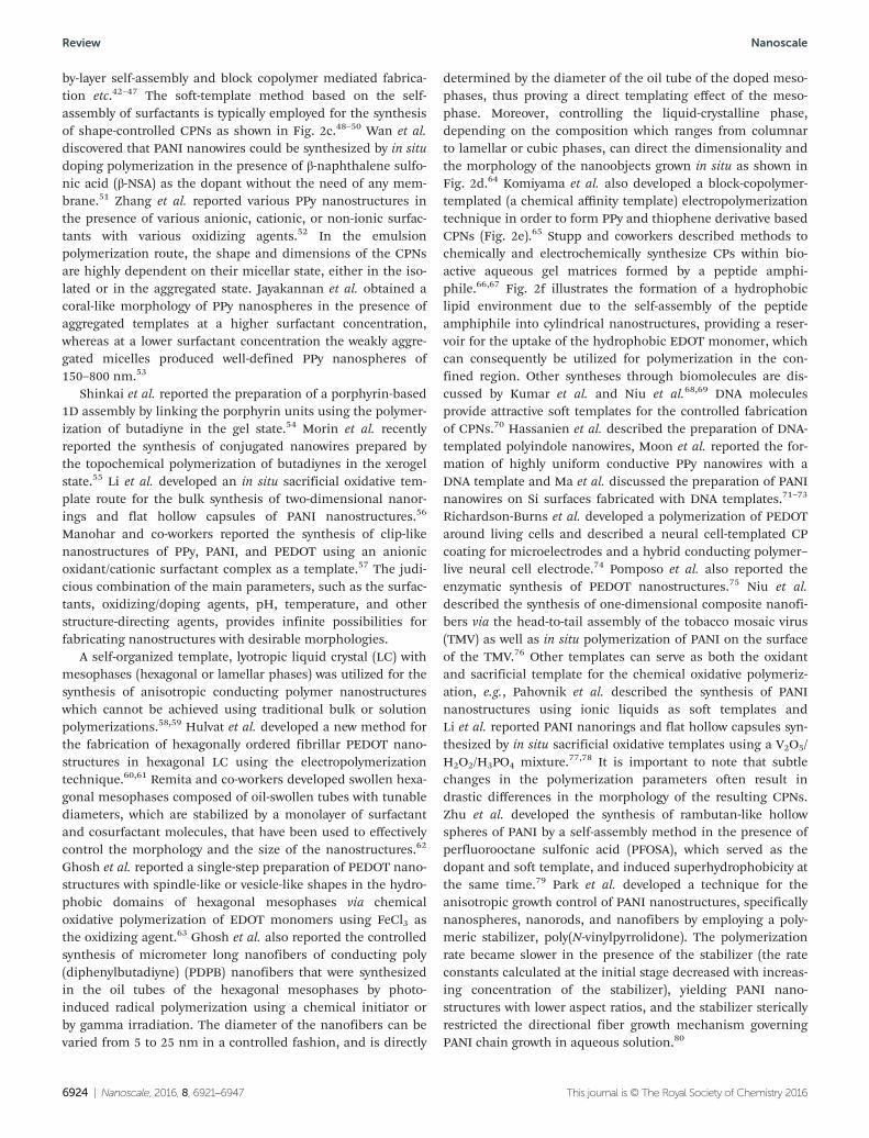
by-layer self-assembly and block copolymer mediated fabrica-tion etc.42–47 The soft-template method based on the self-assembly of surfactants is typically employed for the synthesisof shape-controlled CPNs as shown in Fig. 2c.48–50 Wan et al.discovered that PANI nanowires could be synthesized by in situdoping polymerization in the presence of β-naphthalene sulfo-nic acid (β-NSA) as the dopant without the need of any mem-brane.51 Zhang et al. reported various PPy nanostructures inthe presence of various anionic, cationic, or non-ionic surfac-tants with various oxidizing agents.52 In the emulsionpolymerization route, the shape and dimensions of the CPNsare highly dependent on their micellar state, either in the iso-lated or in the aggregated state. Jayakannan et al. obtained acoral-like morphology of PPy nanospheres in the presence ofaggregated templates at a higher surfactant concentration,whereas at a lower surfactant concentration the weakly aggre-gated micelles produced well-defined PPy nanospheres of150–800 nm.53
Shinkai et al. reported the preparation of a porphyrin-based1D assembly by linking the porphyrin units using the polymer-ization of butadiyne in the gel state.54 Morin et al. recentlyreported the synthesis of conjugated nanowires prepared bythe topochemical polymerization of butadiynes in the xerogelstate.55 Li et al. developed an in situ sacrificial oxidative tem-plate route for the bulk synthesis of two-dimensional nanor-ings and flat hollow capsules of PANI nanostructures.56
Manohar and co-workers reported the synthesis of clip-likenanostructures of PPy, PANI, and PEDOT using an anionicoxidant/cationic surfactant complex as a template.57 The judi-cious combination of the main parameters, such as the surfac-tants, oxidizing/doping agents, pH, temperature, and otherstructure-directing agents, provides infinite possibilities forfabricating nanostructures with desirable morphologies.
A self-organized template, lyotropic liquid crystal (LC) withmesophases (hexagonal or lamellar phases) was utilized for thesynthesis of anisotropic conducting polymer nanostructureswhich cannot be achieved using traditional bulk or solutionpolymerizations.58,59 Hulvat et al. developed a new method forthe fabrication of hexagonally ordered fibrillar PEDOT nano-structures in hexagonal LC using the electropolymerizationtechnique.60,61 Remita and co-workers developed swollen hexa-gonal mesophases composed of oil-swollen tubes with tunablediameters, which are stabilized by a monolayer of surfactantand cosurfactant molecules, that have been used to effectivelycontrol the morphology and the size of the nanostructures.62
Ghosh et al. reported a single-step preparation of PEDOT nano-structures with spindle-like or vesicle-like shapes in the hydro-phobic domains of hexagonal mesophases via chemicaloxidative polymerization of EDOT monomers using FeCl3 asthe oxidizing agent.63 Ghosh et al. also reported the controlledsynthesis of micrometer long nanofibers of conducting poly(diphenylbutadiyne) (PDPB) nanofibers that were synthesizedin the oil tubes of the hexagonal mesophases by photo-induced radical polymerization using a chemical initiator orby gamma irradiation. The diameter of the nanofibers can bevaried from 5 to 25 nm in a controlled fashion, and is directly
determined by the diameter of the oil tube of the doped meso-phases, thus proving a direct templating effect of the meso-phase. Moreover, controlling the liquid-crystalline phase,depending on the composition which ranges from columnarto lamellar or cubic phases, can direct the dimensionality andthe morphology of the nanoobjects grown in situ as shown inFig. 2d.64 Komiyama et al. also developed a block-copolymer-templated (a chemical affinity template) electropolymerizationtechnique in order to form PPy and thiophene derivative basedCPNs (Fig. 2e).65 Stupp and coworkers described methods tochemically and electrochemically synthesize CPs within bio-active aqueous gel matrices formed by a peptide amphi-phile.66,67 Fig. 2f illustrates the formation of a hydrophobiclipid environment due to the self-assembly of the peptideamphiphile into cylindrical nanostructures, providing a reser-voir for the uptake of the hydrophobic EDOT monomer, whichcan consequently be utilized for polymerization in the con-fined region. Other syntheses through biomolecules are dis-cussed by Kumar et al. and Niu et al.68,69 DNA moleculesprovide attractive soft templates for the controlled fabricationof CPNs.70 Hassanien et al. described the preparation of DNA-templated polyindole nanowires, Moon et al. reported the for-mation of highly uniform conductive PPy nanowires with aDNA template and Ma et al. discussed the preparation of PANInanowires on Si surfaces fabricated with DNA templates.71–73
Richardson-Burns et al. developed a polymerization of PEDOTaround living cells and described a neural cell-templated CPcoating for microelectrodes and a hybrid conducting polymer–live neural cell electrode.74 Pomposo et al. also reported theenzymatic synthesis of PEDOT nanostructures.75 Niu et al.described the synthesis of one-dimensional composite nanofi-bers via the head-to-tail assembly of the tobacco mosaic virus(TMV) as well as in situ polymerization of PANI on the surfaceof the TMV.76 Other templates can serve as both the oxidantand sacrificial template for the chemical oxidative polymeriz-ation, e.g., Pahovnik et al. described the synthesis of PANInanostructures using ionic liquids as soft templates andLi et al. reported PANI nanorings and flat hollow capsules syn-thesized by in situ sacrificial oxidative templates using a V2O5/H2O2/H3PO4 mixture.77,78 It is important to note that subtlechanges in the polymerization parameters often result indrastic differences in the morphology of the resulting CPNs.Zhu et al. developed the synthesis of rambutan-like hollowspheres of PANI by a self-assembly method in the presence ofperfluorooctane sulfonic acid (PFOSA), which served as thedopant and soft template, and induced superhydrophobicity atthe same time.79 Park et al. developed a technique for theanisotropic growth control of PANI nanostructures, specificallynanospheres, nanorods, and nanofibers by employing a poly-meric stabilizer, poly(N-vinylpyrrolidone). The polymerizationrate became slower in the presence of the stabilizer (the rateconstants calculated at the initial stage decreased with increas-ing concentration of the stabilizer), yielding PANI nano-structures with lower aspect ratios, and the stabilizer stericallyrestricted the directional fiber growth mechanism governingPANI chain growth in aqueous solution.80
Review Nanoscale
6924 | Nanoscale, 2016, 8, 6921–6947 This journal is © The Royal Society of Chemistry 2016
2.2. Template-free synthesis
The template-free method is considered to be a simple,straightforward and cost effective technique for the synthesisof CPNs without the need of a template or post-treatment fortemplate removal.81,82 Additionally, uniform nanostructuresare formed, which are easily scalable and reproducible. Tem-plate-free synthetic strategies such as interfacial polymeriz-ation (self-assembly), electrospinning and radiolysis are brieflydiscussed. Various CPNs such as nanotubes, nanofibers,hollow spheres, etc. were successfully synthesized by thetemplate-free method. Typically, PANI with one dimensional(1D) morphology in aqueous solution has been intensivelyinvestigated to fabricate 1D PANI nano structures in theabsence of templates.83 Dind et al. and Park et al. reported aone-pot surfactant-free route to synthesize PANI hollow nano-spheres using controllable incontinuous nanocavities.84,85
Furthermore, an oriented nanowire was also prepared throughcontrolled nucleation and growth during a stepwise electro-chemical deposition process without using any structure con-trolling agent.86 Tseng et al. developed a site-specificelectrochemical method for the fabrication of individuallyaddressable PPy, PANI and PEDOT nanowires on microelec-trode junctions.87 Similarly, Ramanathan et al. created arraysof individually addressable CP nanowires of controlled dimen-sions and high aspect ratios with site-specific positioning,alignment and chemical compositions.88 Up to now, a rangeof PANI nanostructures such as nanotubes,89,90 nanowiresor fibers,91,92 have been prepared by the template-free method.
2.2.1. Self-assembly or interfacial polymerization. Theinterfacial polymerization (IP) technique is useful for synthe-sizing CPNs via oxidative coupling processes at low tempera-tures and with limited side reactions, and can avoid the use ofcatalysts or phase transfer agents. This involves step polymeriz-ation of two reactive monomers or agents, which are dissolved,respectively, in two immiscible phases and the reaction takesplace at the interface of the two liquids. Interestingly, massand charge diffusion through a liquid–liquid interface controlthe crystallinity, size and shape of CPNs.93–96 Huang et al.used an aqueous–organic interfacial polymerization methodfor the synthesis of high quality PANI nanofibers having dia-meters of 30–50 nm under ambient conditions.97 Haldorai et al.described IP as a reliable non-template approach with an easysynthesis and economic viability for synthesizing poly(aniline-co-p-phenylenediamine) [poly(Ani-co-p-PD)] nanorods via amicrowave-assisted aqueous–ionic liquid interfacial oxidativepolymerization in the presence of acid dopants.98 Du et al.have reported the formation of PANI nanotubes under varioussynthesis conditions without templates.99 Nuraje et al. alsodescribed the interfacial crystallization of conductive polymersat the liquid–liquid interface, allowing PANI and PPy polymersto form single crystalline nanocrystals in a rice-like shape inthe dimensions of 63 nm × 12 nm for PANI and 70 nm ×20 nm for PPy.100,101 Ma et al. reported unique alignedPANI belts doped with dodecatungstosilic acid (H4SiW12O40)that were synthesized by the interfacial control method
which demonstrated a superior performance in theconductivity.102
2.2.2. Electrospinning. Electrospinning is one of the mostefficient techniques to create continuous and aligned conduct-ing polymer nanofibers and composites under a high electricfield.103 Electrospinning occurs with the development of a jetwhen the repulsion forces of a charged solution overcome thesurface tension of the solution under a high electrostatic field.Finally, the spun fibers are deposited commonly as a non-woven web on a collector. MacDiarmid et al. reported the fabri-cation of PANI nanowires with sub-100 nm diameters dopedwith DL-camphorsulfonic acid.104 Chronakis et al. reportedelectrospun PPy/PEO nanofibers with diameters in the rage ofabout 70–300 nm with improved electrical conductivity andChoi et al. reported a method of fabricating electrospunPEDOT:poly(styrenesulfonate) (PSS)/PVP nanofibers.105,106
Feng et al. also reported the fabrication of aligned PEDOTfibers and tubes based on electrospinning and oxidativechemical polymerization.107 The electrospinning processappears to be the single method that can produce continuouslong nanofibers; however, in order to assist in the fiber for-mation, non-conducting polymers or supports are usuallyadded which lower the conductivity of the electrospun compo-site fibers.
2.2.3. Radiolysis. Alternatively, γ-irradiation has been usedextensively to generate nanostructured materials underambient temperature and pressure.108,109 In comparison toother methods, some of the advantages of the radiationinitiated polymerization over conventional methods are: (i) theabsence of foreign matter, such as the initiator, catalyst, etc.;(ii) polymerization at room temperature or in the solid state;(iii) the rate of the initiation step can easily be controlled byvarying the dose rate; and (iv) the initiating radicals can beproduced uniformly by γ-irradiation. Pillalamarri et al. develo-ped the radiolytic synthesis of PANI nanofibers with diametersof 50–100 nm and lengths of 1–3 μm as well as nanorodswith typical lengths between 5 and 10 μm and diameters of250–500 nm.110 Karim et al. also reported the synthesisof highly uniform conducting PPy with particle sizes of100–500 nm by an in situ gamma radiation (60Co γ-ray)-induced chemical oxidative polymerization method.111 Huanget al. developed an one pot method for polyaniline/silver com-posites under γ-irradiation which revealed that the PANI nano-fibers were formed by the reaction of aniline cation radicalsformed by the reaction of the aniline cation and •OH, and theAg NPs were formed by the reaction of Ag+ and e−aq.
112
Recently Remita’s group reported a series of radiolytic synth-eses of PEDOT nanostructures and also studied the mecha-nism in detail. Lattach et al. developed self-assembledhydrophilic PEDOT nanostructures via an oxidation processinitiated by HO• radicals produced by water radiolysis withoutusing chemical initiators.113 In continuation of that work, adetailed study of the effect of oxidizing agents on radiolyticPEDOT polymerization has been reported by Remita and co-workers. Interestingly, HO• radicals led to PEDOT–OH globularnanostructures with hydrophilic properties and N3
• radicals
Nanoscale Review
This journal is © The Royal Society of Chemistry 2016 Nanoscale, 2016, 8, 6921–6947 | 6925
enabled the formation of amphiphilic PEDOT–N• fibrillarnanostructures.114 Cui et al. reported the radiation-inducedreduction (action of e−aq under a N2 atmosphere) polymeriz-ation route for the synthesis of PEDOT nanostructures.115 Cuiet al. also reported the template free synthesis of spherical PPyNPs using a radiolytic method as a novel approach.116 Colettaet al. also reported a new alternative method based on electronbeam irradiation for the synthesis and detailed mechanisticstudies of PEDOT nanostructures using time-resolved absorp-tion spectroscopy coupled with pulsed radiolysis.117 This “fast”technique offers several advantages: it enables, via the pulsedelectron accelerator, (i) the generation of oxidizing species inthe aqueous irradiated medium in a very short time, (ii) quan-titative knowledge of the concentration of the oxidizingspecies, (iii) the appearance and disappearance of the transi-ent species produced during EDOT oxidation to be followed inreal-time by absorption spectroscopy and the estimation of therate constants of the involved consecutive reactions. By com-bining the experimental and theoretical study it was demon-strated that, in air and under a N2O atmosphere, HO•-inducedoxidation of EDOT implies the formation of a transientspecies, namely an EDOT•+ cation radical, which dimerizesand deprotonates leading to a stable product, namely anEDOT2 dimer. This result proves that PEDOTox growth is not achain reaction. On the contrary, it proceeds through a step-by-step mechanism made up of the following recurrent steps: oxi-dation/activation, a growth/chain length increase and deproto-nation. The quantitative synthesis of PEDOTred polymersthroughout a reduction–polymerization process also implies astep-by-step mechanism and requires the use of two hydratedelectrons per EDOT molecule.
2.3. Conducting polymer hydrogels
Hydrogels are polymeric networks that have a high level ofhydration and three-dimensional (3D) microstructures and canbe made electrically conductive by embedding various CPswhich combine the unique properties of hydrogels with theelectrical and optical properties of semiconductors.118–121
Conducting polymer hydrogels (CPHs) are a class of uniquematerials that synergize the advantages of conducting poly-mers and polymer hydrogels. The CPHs have hierarchicallyporous nanostructures crosslinked in a three-dimensional (3D)way, which afford their stable mechanical, unique chemicaland physical, and outstanding electrochemical properties forpotential use in electrochemical applications, including long-term energy storage devices, lithium-ion battery (LIB) electro-des, electrochemical capacitors (ECs), biofuel cells, printableelectronic devices, and biosensors.122–126 Different CPs such asPEDOT, PANI, PPy and PTh can be used as the electrical back-bone of the material.127–131 A PANI hydrogel free of insulatingpolymers has been synthesized by using phytic acid as boththe gelator and the dopant to directly form a gel network,132
an amphiphilic thiophene derivative hydrogel with unusualtwo dimensional building blocks has been synthesized in onestep via a combination of oxidative coupling polymerizationand non-covalent crosslinking133 and a PPy nanotube hydrogel
with controlled morphology has been synthesized by oxidativepolymerization in the presence of dye molecules as tem-plates.134 Other interesting CP based materials, aerogels, are anovel class of highly porous nanomaterials that have uniquephysicochemical properties such as ultra-low density, largespecific area, disordered open pores, elaborate 3D networks,etc.135,136 Zhang and co-workers reported a series of CP aero-gels based on PEDOT/poly(styrenesulfonate) (PSS); however,the existence of the required non-conducting PSS would sig-nificantly limit the application of PEDOT/PSS aerogels.137,138
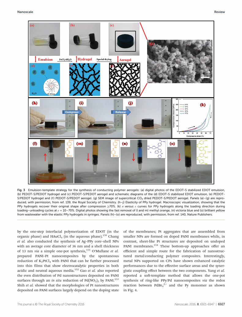
However, they developed a new method based on an emulsiontemplate for the synthesis of CP aerogels by supercriticaldrying or freeze drying of the as-synthesized PEDOT-S/PEDOThydrogels with superior adsorption capacity and enhancedelectrochemical capacitance as shown in Fig. 3a.139 Fig. 3a–fshow that the waterborne EDOT derivative, sodium 4-(2,3-di-hydrothieno[3,4-b][1,4]dioxin-2-yl)-methoxy-butane-1-sulfonate(EDOT-S), serves as a reactive surfactant to disperse and stabil-ize the hardly soluble EDOT to form a stable emulsion. Theresulting emulsion, acting as a sol, was converted into a hydro-gel by triggering the oxidative coupling polymerization of bothEDOT-S and EDOT with the oxidizing agent. After using super-critical CO2 or freeze drying the resulting hydrogel precursor,the PEDOT-S/PEDOT aerogel was obtained successfully.A typical SEM image, as shown in Fig. 3g, indicates that theresulting aerogel is rich in hierarchical pores of 2–50 nm andthese macropores are randomly self-assembled by the inter-connected sphere-like nanostructures. There is a huge challengeto make CP hydrogels elastic due to the inherent rigidity of theconjugated macromolecular chains resulting from the deloca-lized p-electron system. Recently, Lu et al. reported the prepa-ration of elastic, conductive, PPy hydrogels and sponges.140
The PPy hydrogel could be compressed by ≥70% and return toits original shape in 30 seconds as shown in Fig. 3h–j. Fromthe compressive stress versus strain curves for the PPy hydro-gels along the loading direction during loading–unloadingcycles at ε = 10–70%, the compressive stress returned to theorigin after unloading for each strain ε (Fig. 3k).
2.4. Conducting polymer based composites
Polymer nanocomposites have attracted considerable researchinterest due to their unique physicochemical properties thatcannot be obtained with the individual components, and theirpotential for versatile applications ranging from environ-mental remediation, energy storage and novel catalysts to bio-medical applications etc.141–143 CP based composite materialsare also gaining importance due to their synergistic andhybrid properties derived from several components.144 Compo-sites of noble metals and CPs exhibit many excellent propertiesbecause of the combination of different functional com-ponents in a single unit. It has been reported that CPs areusually employed as a supporting matrix to incorporate noblemetal NPs for catalytic applications.145–148 Zhang et al. develo-ped highly dispersed composite gold core/polythiophene shellNPs with the potential for electronic device applications.149
Shi et al. simply synthesized Au–PEDOT core–shell nanocables
Review Nanoscale
6926 | Nanoscale, 2016, 8, 6921–6947 This journal is © The Royal Society of Chemistry 2016
by the one-step interfacial polymerization of EDOT (in theorganic phase) and HAuCl4 (in the aqueous phase).150 Changet al. also conducted the synthesis of Ag–PPy core–shell NPswith an average core diameter of 36 nm and a shell thicknessof 13 nm via a simple one-pot synthesis,151 O’Mullane et al.prepared PANI–Pt nanocomposites by the spontaneousreduction of K2PtCl4 with PANI that can be further processedinto thin films that show electrocatalytic properties in bothacidic and neutral aqueous media.152 Gao et al. also reportedthe even distribution of Pd nanostructures deposited on PANIsurfaces through an in situ reduction of Pd(NO3)2 by PANI.153
Shih et al. showed that the morphologies of Pt nanostructuresdeposited on PANI surfaces largely depend on the doping state
of the membranes; Pt aggregates that are assembled fromsmaller NPs are formed on doped PANI membranes while, incontrast, sheet-like Pt structures are deposited on undopedPANI membranes.154 These bottom-up approaches offer anefficient and simple route for the fabrication of nanostruc-tured metal/conducting polymer composites. Interestingly,metal NPs supported on CPs have shown enhanced catalyticperformances due to the effective surface areas and the syner-gistic coupling effect between the two components. Yang et al.reported a soft-template method that allows the one-potsynthesis of ring-like PPy/Pd nanocomposites via the redoxreaction between PdBr4
2− and the Py monomer as shownin Fig. 4.
Fig. 3 Emulsion-template strategy for the synthesis of conducting polymer aerogels: (a) digital photos of the EDOT-S stabilized EDOT emulsion,(b) PEDOT-S/PEDOT hydrogel and (c) PEDOT-S/PEDOT aerogel and schematic diagrams of the (d) EDOT-S stabilized EDOT emulsion, (e) PEDOT-S/PEDOT hydrogel and (f ) PEDOT-S/PEDOT aerogel. (g) SEM image of supercritical CO2 dried PEDOT-S/PEDOT aerogel. Panels (a)–(g) are repro-duced, with permission, from ref. 139, the Royal Society of Chemistry. (h–j) Elasticity of PPy hydrogel. Macroscopic visualization, showing that thePPy hydrogels recover their original shape after compression ≥70%. (k) σ versus ε curves for PPy hydrogels along the loading direction duringloading–unloading cycles at ε = 10–70%. Digital photos showing the fast removal of (l and m) methyl orange, (n) victoria blue and (o) brilliant yellowfrom wastewater with the elastic PPy hydrogels in syringes. Panels (h)–(o) are reproduced, with permission, from ref. 140, Nature Publishers.
Nanoscale Review
This journal is © The Royal Society of Chemistry 2016 Nanoscale, 2016, 8, 6921–6947 | 6927
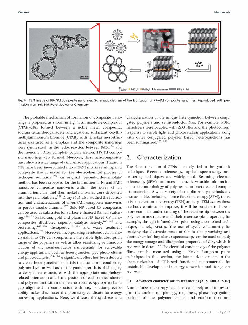
The probable mechanism of formation of composite nano-rings is proposed as shown in Fig. 4. An insoluble complex of(CTA)2PdBr4 formed between a noble metal compound,sodium tetrachloropalladate, and a cationic surfactant, cetyltri-methylammonium bromide (CTAB), with lamellar mesostruc-tures was used as a template and the composite nanoringswere synthesized via the redox reaction between PdBr4
2− andthe monomer. After complete polymerization, PPy/Pd compo-site nanorings were formed. Moreover, these nanocompositeshave shown a wide range of tailor-made applications. PlatinumNPs have been incorporated into a PANI matrix resulting in acomposite that is useful for the electrochemical process ofhydrogen evolution.155 An original ‘second-order-template’method has been proposed for the fabrication of Ni and PANInanotube composite nanowires within the pores of analumina template, and then nickel nanowires were depositedinto these nanotubules.156 Drury et al. also studied the fabrica-tion and characterization of silver/PANI composite nanowiresin porous anodic alumina.157 Gold NP based CP compositescan be used as substrates for surface enhanced Raman scatter-ing.158,159 Palladium, gold and platinum NP based CP nano-composites illustrated superior catalytic activity,160–165 andbiosensing,166–170 therapeutic,171,172 and water treatmentapplications.173 Moreover, incorporating semiconductor nano-crystals into CPs can complement the visible light absorptionrange of the polymers as well as allow sensitizing or immobil-ization of the semiconductor nanocrystals for renewableenergy applications such as heterojunction-type photovoltaicsand photocatalysis.174–176 A significant effort has been devotedto create heterojunction materials that contain a conductingpolymer layer as well as an inorganic layer. It is challengingto design heterostructures with the appropriate morphology-related orientation and band position of each semiconductorand polymer unit within the heterostructure. Appropriate bandgap alignment in combination with easy solution-process-ability makes this material a promising candidate for energyharvesting applications. Here, we discuss the synthesis and
characterization of the unique heterojunction between conju-gated polymers and semiconductor NPs. For example, PDPBnanofibers were coupled with ZnO NPs and the photocurrentresponse to visible light and photocatalysis applications alongwith other conjugated polymer based heterojunctions hasbeen summarized.177–180
3. Characterization
The characterization of CPNs is closely tied to the synthetictechnique. Electron microscopy, optical spectroscopy andscattering techniques are widely used. Scanning electronmicroscopy (SEM) continues to provide valuable informationabout the morphology of polymer nanostructures and compo-site materials. A wide variety of complimentary methods arealso available, including atomic force microscopy (AFM), trans-mission electron microscopy (TEM) and cryo-TEM etc. As thesemethods continue to improve, it will be possible to have amore complete understanding of the relationship between thepolymer nanostructure and their macroscopic properties, forexample, through infrared absorption using a combined tech-nique, namely, AFMIR. The use of cyclic voltammetry forstudying the electronic states of CPs is also promising andelectrochemical impedance spectroscopy can be used to studythe energy storage and dissipation properties of CPs, which isreviewed in detail.181 The electrical conductivity of the polymerfilms can be measured using a Kelvin four-point probetechnique. In this section, the latest advancements in thecharacterization of CP-based functional nanomaterials forsustainable development in energy conversion and storage arereviewed.
3.1. Advanced characterization techniques (AFM and AFMIR)
Atomic force microscopy has been extensively used to investi-gate the surface morphology, roughness, phase segregation,packing of the polymer chains and conformation and
Fig. 4 TEM image of PPy/Pd composite nanorings. Schematic diagram of the fabrication of PPy/Pd composite nanorings. Reproduced, with per-mission, from ref. 146, Royal Society of Chemistry.
Review Nanoscale
6928 | Nanoscale, 2016, 8, 6921–6947 This journal is © The Royal Society of Chemistry 2016
mapping the distribution of the electric charges etc. of con-ducting polymers. Taranekar et al.182 studied the formation ofunique ‘nanoscale’ morphologies due to phase-segregation ofpolysiloxane domains and cross-linked PPy from the AFMimages. Pruneanu et al.183 studied the self-assembly of DNA-template PPy nanowires using the noncontact mode. Anotherwidely used application of dynamic modes using electricalforce microscopy (EFM) provides the possibility of probing thelocalized charge distribution, surface potential, and dopingprofiles at the surface.184,185 Takami et al. measured the con-ductivity of polydiacetylene thin films using double-tip scan-ning tunneling microscopy.186 Scanning Kelvin probemicroscopy (KPM), which identifies the local surface potential,offers the possibility of distinguishing between regions withdifferent chemical natures or compositions.187 For example,Semenikhin et al.188 studied the evidence of local structuralinhomogeneity and non-uniform dopant distribution in con-ducting polybithiophene (PBT) and the origin and characteriz-ation of the structural inhomogeneity and local potential
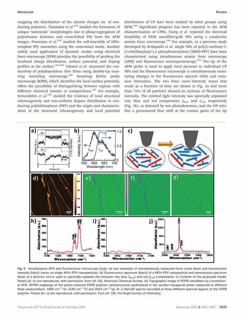
distribution of CP have been studied by other groups usingKFM.189 Significant progress has been reported in the AFMcharacterization of CPNs. Tseng et al. reported the electricalbistability of PANI nanofiber/gold NPs using a conductiveatomic force microscope.190 For example, in a previous studydeveloped by Kobayashi et al. single NPs of poly(2-methoxy-5-(2-ethylhexyloxy)-1,4 phenylenevinylene) (MEH-PPV) have beencharacterized using simultaneous atomic force microscopy(AFM) and fluorescence microspectroscopy.191 The tip of theAFM probe is used to apply local pressure to individual CPNPs and the fluorescence microscope is simultaneously moni-toring changes in the fluorescence spectral shifts and emis-sion intensities. The two force curve–intensity traces thatresult as a function of time are shown in Fig. 5a and morethan 70% of all particles showed an increase of fluorescenceintensity. The emitted light intensity was spectrally separatedinto blue and red components Iblue and Ired, respectively(Fig. 5b), as detected by two photodetectors, and the NP exhi-bits a pronounced blue shift at the contact point of the tip
Fig. 5 Simultaneous AFM and fluorescence microscopy study: (a) two examples of simultaneously measured force curve (blue) and fluorescenceintensity (black) traces on single MEH-PPV nanoparticles. (b) Fluorescence spectrum (black) of a MEH-PPV nanoparticle and transmission spectrum(blue) of a dichroic mirror used to spectrally separate the emission into blue (Iblue) and red (Ired) components. (c) Scheme of the proposed model.Panels (a)–(c) are reproduced, with permission, from ref. 191, American Chemical Society. (d) Topographic image of PDPB nanofibers by convention-al AFM. AFMIR mappings of the photo-induced PDPB polymer nanostructures synthesized in the swollen hexagonal phase measured at differentfixed wavenumbers: 1490 cm−1 (e), 2146 cm−1 (f ) and 3054 cm−1 (g). (h–j) NanoIR spectra recorded at three different spectral regions of the PDPBpolymer. Panels (d)–( j) are reproduced, with permission, from ref. 192, the Royal Society of Chemistry.
Nanoscale Review
This journal is © The Royal Society of Chemistry 2016 Nanoscale, 2016, 8, 6921–6947 | 6929
with the particle surface, which is reversed upon retraction ofthe tip. The phenomena are interpreted in terms of the localdisturbance of the MEH-PPV chain conformation by the probetip and the contact of the sharp probe tip (with a tip radius of7 nm) with the particle surface causes local conformationaldisruption of the MEH-PPV chains near the tip as shown inFig. 5c. Ghosh and co-workers have also been able to directlyobserve the polymer regions via AFM topography imaging andthen rapidly acquire high-resolution local chemical spectra atselected regions on the sample by the AFMIR technique usinga nanoIR instrument with a tunable pulsed laser as the IRsource (Fig. 5d–g and h–j).192 When the sample absorbs the IRlaser pulse, it warms via a photothermal effect, resulting ina rapid thermal expansion of the absorbing region of thesample. Consequently, the thermal expansion pulse impactsthe tip of the AFM cantilever and causes it to oscillate. As theamplitude of oscillations is proportional to the absorption, itis possible to record local infrared absorption spectra andmake chemical maps by scanning the surface at a given wave-length. The surface topography of the PDPB nanostructuresshowed that well dispersed fibers formed during depositionon the ZnSe substrates as shown in Fig. 5d.
Fig. 5e shows the IR absorption signal measured by the can-tilever when the laser is set at 1494 cm−1. The brighter purplecolors indicate regions of stronger IR absorption at this par-ticular wavenumber and the absorption intensity discriminatesthe polymer domains which are distinct from the low-intensitybackground (green color). The spectral region at 2300–2000 cm−1 of the triple bond stretching was thoroughlyanalyzed and the disappearance of the monomer band at2146 cm−1 after irradiation demonstrates that the polymeri-zation is complete (Fig. 5g). A strong signal is measured whenthe wavenumber is fixed at 3054 cm−1 which originates fromthe benzene ring in the PDPB polymer (Fig. 5h). The combi-nation of the nanoscale probe from an atomic force micro-scope with a tunable IR source provides simultaneousmeasurements of the nanoscale morphology along with chemi-cal composition mapping (Fig. 5h–j) and confirms the pres-ence of PDPB polymer nanostructures on the substrate.
3.2. TEM characterization and understanding themechanism of formation
Transmission electron microscopy is a useful tool for studyingthe formation of CPNs. Liu et al. reported direct imaging ofthe in situ electrochemical deposition of PEDOT using TEMwith an electrochemical liquid flow cell. PEDOT depositionbegan preferentially at the edge of the glassy carbon anodesand then oligomers were observed to form near the electrodesurfaces (Fig. 6a).193 As the reaction continued, both thenucleation of new domains as well as the growth of pre-exist-ing PEDOT deposits was observed (Fig. 6b), leading to systema-tic increases in film thickness and roughness (Fig. 6c).Moreover, EDS mapping can be used to confirm the elementalcomposition of the deposited thin film. The elementalmapping results for sulfur, carbon, oxygen (both PEDOT andcounterion) and chlorine (from the counterion) with their
expected distribution are shown in the inset of Fig. 6c.193 Themorphology of CPNs in aqueous solution can be observed byfreezing the system at equilibrium through cryo-TEM, withoutphase transition and possible aggregation resulting fromdrying procedures.194 A series of reports have been publishedby Remita and co-workers utilizing cryo-TEM for thecharacterization of CPNs.195–197
There is another interesting report on in situ monitoring ofthe nucleation of PANI NPs from micelles using nuclear mag-netic resonance (NMR).198 Wu et al. studied the nucleation ofpolymeric NPs covering the generation of the clusters and theforthcoming aggregation to the nuclei by in situ 1H NMRexperiments as shown in Fig. 6d. The changes from anilinetetramers, water (HOD) as well as SDS, have been followed inorder to correlate the signal transitions from each species intime sequence. A continuous downfield shift is observed forthe HOD peak due to the acceptance of the protons releasedduring the formation of aniline oligomers, then the resonancefrom the bulk water shifts upfield continuously even thoughthe total shift is only 4.0 Hz as shown in Fig. 6d. Additionally,a new broad peak at 4.86 ppm, possibly from aniline tetra-mers, appeared. This suggests the local environment of thebulk water (4.83 ppm) is enriched with some compounds con-taining more electron-donating groups, and an extra waterphase has been formed. Based on NMR results, the nucleationof PANI in the rod-like micelles has been proposed to occur asshown in Fig. 6e. The tetramers are identified as the actualnucleation agents in this process and the co-operation of thetetramer deprotonation and the fusion of the protective SDSmicelles causes the steady nucleation. The nucleation proceedswith the translocation of the protonated tetramers from themicelles to the aqueous bulk, deprotonation of the oligomersto induce the micellar fusion, and intermolecular packing toform nascent nuclei.
3.3. Electrochemical characterization
Electrochemical measurements have been used for evaluationof the position of energy levels and the band gap of the CPs.Electrochemical techniques are also useful for investigatingthe reversibility, stability and rearrangements of the polymerfilms deposited on the electrode. Voltammetry measurementsgive information regarding redox properties, the oxidation andreduction potentials. The oxidation corresponds to electronextraction from the highest occupied molecular orbital,HOMO, level and can be correlated to the ionization potential,whereas the reduction potential is associated with electronaffinity and indicates the lowest unoccupied molecular orbital,LUMO, level.198,199 In cyclic voltammetry (CV), the current ismeasured while the voltage is continuously varied (linearsweep). The input parameters are therefore the initial andfinal voltages and the scan rate, while the output parametersare the voltage values at which the peaks occur and the currentintensities. For some polymers, either anodic or cathodicsignals are not well resolved. In such cases, differential pulsevoltammetry (DPV) and square wave voltammetry (SWV) tech-niques, where the current is measured before and after each
Review Nanoscale
6930 | Nanoscale, 2016, 8, 6921–6947 This journal is © The Royal Society of Chemistry 2016
potential step change (staircase voltammetry), can be used.The combination of electrochemical impedance spectroscopy(EIS) with CV provides a powerful tool to understand the elec-trochemical characteristics of CPs, including the double-layercapacitance, diffusion impedance, determination of the rateof charge transfer, charge transport processes and solutionresistance.200–202 To develop CPs, including PANI, PPy, PThand their derivatives, as electrode materials for specific appli-cations, such as batteries, fuel cells and interfaces, CV can beused to explore the capacity of the charge transfer density andthe integrated surface area of the CV graph corresponds to thecapacity of the charge transfer through the polymeric film. EISallows the investigation of charge and mass transport kineticsand charging processes taking place within the analyzedmaterial and at the active interfaces of the system. The general-ized transmission line circuit model predicts the relevantimpedance features of CPs in terms of a Nyquist plot203 basedon a mathematical approach. The two semi-circles at thehighest frequencies, induced by the processes at the metal–polymer and polymer–solution interfaces, are not alwaysdetectable. Often one or even one-half of a semi-circle isobtained that partially overlaps with another, depending on
the characteristics of the interfacial processes in terms of theenergy (resistance) to overcome at the relevant interface. More-over, due to non-homogeneous separation surfaces these semi-circles are deformed.204 The stability can be checked by theKramers–Kronig transformation and the results can be inter-preted as an equivalent circuit (EC) model. Self-made fittingprograms can normally be used to construct a quantitativefitting by adopting the correct electrical circuit; however, theobtained parameters do not have physical equivalents. There-fore, it is difficult to extract information about the electrodereaction mechanism.205 The EIS and CV measurements byAbidian and co-workers showed that PEDOT film and PEDOTnanotube coatings had a lower impedance and higher chargecapacity density (CCD) than PPy film and PPy nanotube coat-ings deposited with the same deposition charge density.206,207
Fig. 7a shows the CV graph of a PPy film, a PEDOT film,PPy nanotubes, and PEDOT nanotubes and the charge-capacitydensity (CCD) increased from 0.105 mC cm2 (bare iridium) to1608.3 mC cm2 for the PPy film, 1845.3 mC cm2 for the PPynanotubes, and 2409.4 mC cm2 for the PEDOT nanotubes. Theelectrochemical impedance spectra demonstrated that boththe PEDOT film and PEDOT nanotubes had lower impedance
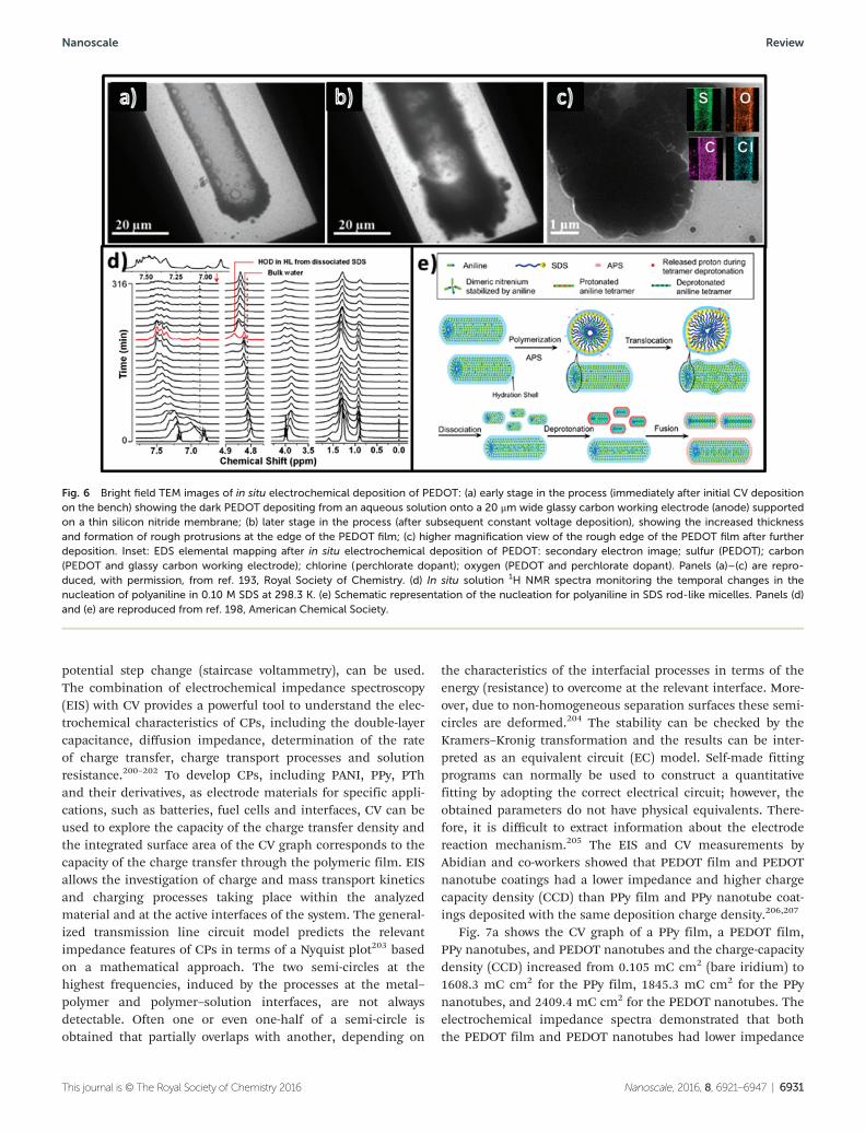
Fig. 6 Bright field TEM images of in situ electrochemical deposition of PEDOT: (a) early stage in the process (immediately after initial CV depositionon the bench) showing the dark PEDOT depositing from an aqueous solution onto a 20 μm wide glassy carbon working electrode (anode) supportedon a thin silicon nitride membrane; (b) later stage in the process (after subsequent constant voltage deposition), showing the increased thicknessand formation of rough protrusions at the edge of the PEDOT film; (c) higher magnification view of the rough edge of the PEDOT film after furtherdeposition. Inset: EDS elemental mapping after in situ electrochemical deposition of PEDOT: secondary electron image; sulfur (PEDOT); carbon(PEDOT and glassy carbon working electrode); chlorine (perchlorate dopant); oxygen (PEDOT and perchlorate dopant). Panels (a)–(c) are repro-duced, with permission, from ref. 193, Royal Society of Chemistry. (d) In situ solution 1H NMR spectra monitoring the temporal changes in thenucleation of polyaniline in 0.10 M SDS at 298.3 K. (e) Schematic representation of the nucleation for polyaniline in SDS rod-like micelles. Panels (d)and (e) are reproduced from ref. 198, American Chemical Society.
Nanoscale Review
This journal is © The Royal Society of Chemistry 2016 Nanoscale, 2016, 8, 6921–6947 | 6931
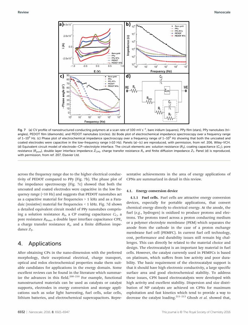
across the frequency range due to the higher electrical conduc-tivity of PEDOT compared to PPy (Fig. 7b). The phase plot ofthe impedance spectroscopy (Fig. 7c) showed that both theuncoated and coated electrodes were capacitive in the low fre-quency range (<10 Hz) and suggests that PEDOT nanotubes actas a capacitive material for frequencies > 1 kHz and as a Fara-daic (resistive) material for frequencies < 1 kHz. Fig. 7d showsa detailed equivalent circuit model of PPy nanotubes compris-ing a solution resistance RS, a CP coating capacitance CC, apore resistance RPore, a double layer interface capacitance CPE,a charge transfer resistance Rt, and a finite diffusion impe-dance ZT.
4. Applications
After obtaining CPs in the nano-dimension with the preferredmorphology, their exceptional electrical, charge transport,optical and redox electrochemical properties make them suit-able candidates for applications in the energy domain. Someexcellent reviews can be found in the literature which summar-ize the advances in this field.208–210 For example, functionalnanostructured materials can be used as catalysts or catalystsupports, electrodes in energy conversion and storage appli-cations such as solar light harvesting, fuel cells, solar cells,lithium batteries, and electrochemical supercapacitors. Repre-
sentative achievements in the area of energy applications ofCPNs are summarized in detail in this review.
4.1. Energy conversion device
4.1.1 Fuel cells. Fuel cells are attractive energy conversiondevices, especially for portable applications, that convertchemical energy directly to electrical energy. At the anode, thefuel (e.g., hydrogen) is oxidized to produce protons and elec-trons. The protons travel across a proton conducting mediumor a polymer electrolyte membrane (PEM) which separates theanode from the cathode in the case of a proton exchangemembrane fuel cell (PEMFC). In current fuel cell technology,cost, performance and durability issues still remain big chal-lenges. This can directly be related to the material choice anddesign. The electrocatalyst is an important key material in fuelcells. However, the catalyst currently used in PEMFCs is basedon platinum, which suffers from low activity and poor dura-bility. The basic requirement of the electrocatalyst support isthat it should have high electronic conductivity, a large specificsurface area and good electrochemical stability. To addressthese issues, CPN based electrocatalysts were developed withhigh activity and excellent stability. Dispersion and size distri-bution of NP catalysts are achieved on CPNs for maximumexploitation and fast kinetics which tend to provide a way todecrease the catalyst loading.211–213 Ghosh et al. showed that,
Fig. 7 (a) CV profile of nanostructured conducting polymers at a scan rate of 100 mV s−1, bare iridium (squares), PPy film (stars), PPy nanotubes (tri-angles), PEDOT film (diamonds), and PEDOT nanotubes (circles). (b) Bode plot of electrochemical impedance spectroscopy over a frequency rangeof 1–105 Hz. (c) Phase plot of electrochemical impedance spectroscopy over a frequency range of 1–105 Hz showing that both the uncoated andcoated electrodes were capacitive in the low-frequency range (<10 Hz). Panels (a)–(c) are reproduced, with permission, from ref. 206, Wiley-VCH.(d) Equivalent circuit model of electrode–CP–electrolyte interface. The circuit elements are: solution resistance (RS), coating capacitance (CC), poreresistance (Rpore), double layer interface impedance ZCPE, charge transfer resistance Rt, and finite diffusion impedance ZT. Panel (d) is reproduced,with permission, from ref. 207, Elsevier Ltd.
Review Nanoscale
6932 | Nanoscale, 2016, 8, 6921–6947 This journal is © The Royal Society of Chemistry 2016
in comparison to their bulk counterparts, CP nanostructuresupported catalytic materials can display improved electrodeactivities for ethanol oxidation which can be useful for directethanol fuel cells (DFFCs).213 A series of Pt NP based electro-catalysts supported on CPs have been used for the electro-catalytic oxidation of methanol. The electrocatalytic activity ofthe CPNs must be greater than that of the corresponding bulkpolymer because of the smaller specific surface area in thelatter case. The effects of electrocatalysts on the performanceof DMFCs have been extensively studied, and CP, PPy, PANI,poly(3-methylthiophene) and poly(o-phenylenediamine) with1D-nanostructures have become good candidates as electro-catalyst supports.214–218 Rajesh et al.214 developed template syn-thesised polyaniline nanotubule supported platinum catalystNPs for methanol oxidation. The activity of the Pt incorporatedtemplate synthesized PANI (Pt/PANITemp) was compared withthat of Pt deposited on conventionally synthesized PANI(Pt/PANI) and Pt loaded on Vulcan XC-72R carbon. The tem-plate-based PANI nanotubular electrode showed higher activitybut also accommodated more Pt than the template-free PANIelectrode. Template-free PANI nanofibres (PANI NFs) withdiameters of about 60 nm were synthesized by interfacialpolymerization and uniform smaller Pt NPs of around 1.8 nm
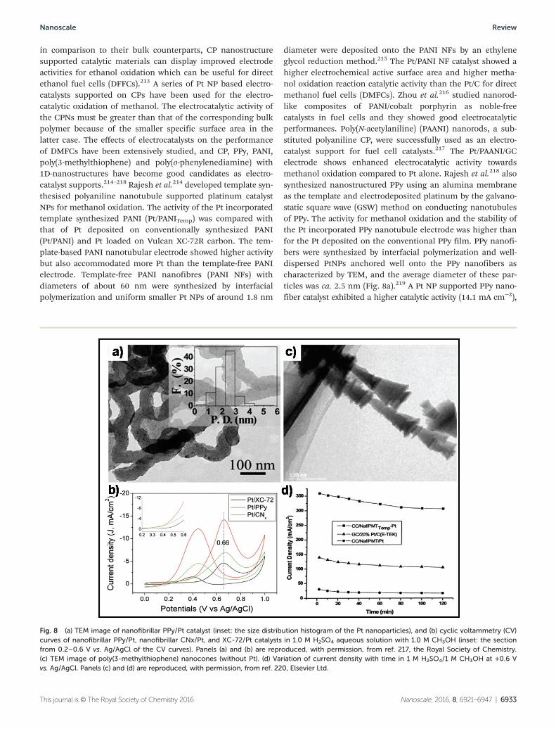
diameter were deposited onto the PANI NFs by an ethyleneglycol reduction method.215 The Pt/PANI NF catalyst showed ahigher electrochemical active surface area and higher metha-nol oxidation reaction catalytic activity than the Pt/C for directmethanol fuel cells (DMFCs). Zhou et al.216 studied nanorod-like composites of PANI/cobalt porphyrin as noble-freecatalysts in fuel cells and they showed good electrocatalyticperformances. Poly(N-acetylaniline) (PAANI) nanorods, a sub-stituted polyaniline CP, were successfully used as an electro-catalyst support for fuel cell catalysts.217 The Pt/PAANI/GCelectrode shows enhanced electrocatalytic activity towardsmethanol oxidation compared to Pt alone. Rajesh et al.218 alsosynthesized nanostructured PPy using an alumina membraneas the template and electrodeposited platinum by the galvano-static square wave (GSW) method on conducting nanotubulesof PPy. The activity for methanol oxidation and the stability ofthe Pt incorporated PPy nanotubule electrode was higher thanfor the Pt deposited on the conventional PPy film. PPy nanofi-bers were synthesized by interfacial polymerization and well-dispersed PtNPs anchored well onto the PPy nanofibers ascharacterized by TEM, and the average diameter of these par-ticles was ca. 2.5 nm (Fig. 8a).219 A Pt NP supported PPy nano-fiber catalyst exhibited a higher catalytic activity (14.1 mA cm−2),
Fig. 8 (a) TEM image of nanofibrillar PPy/Pt catalyst (inset: the size distribution histogram of the Pt nanoparticles), and (b) cyclic voltammetry (CV)curves of nanofibrillar PPy/Pt, nanofibrillar CNx/Pt, and XC-72/Pt catalysts in 1.0 M H2SO4 aqueous solution with 1.0 M CH3OH (inset: the sectionfrom 0.2–0.6 V vs. Ag/AgCl of the CV curves). Panels (a) and (b) are reproduced, with permission, from ref. 217, the Royal Society of Chemistry.(c) TEM image of poly(3-methylthiophene) nanocones (without Pt). (d) Variation of current density with time in 1 M H2SO4/1 M CH3OH at +0.6 Vvs. Ag/AgCl. Panels (c) and (d) are reproduced, with permission, from ref. 220, Elsevier Ltd.
Nanoscale Review
This journal is © The Royal Society of Chemistry 2016 Nanoscale, 2016, 8, 6921–6947 | 6933
significantly higher than that of carbon nitride (CNx)nanofiber supports (7.0 mA cm−2), and the commercial carbonblack powder of Vulcan XC-72 (XC-72) supports (4.6 mA cm−2)(Fig. 8b). A PPy nanofiber supported Pt catalyst shows highercatalytic activity for methanol oxidation and CO-poisoningtolerance.
Rajesh et al.220 developed a template assisted electrochemi-cal synthesis and characterization of conducting poly(3-methylthiophene) (PMT) nanocones on carbon cloth, using analumina membrane template. The HR-TEM images (Fig. 8c) ofthe template synthesized PMT distinctly show a well arrangedhollow cone-in-cone and cone-over-cone structure with theouter diameter of the nanocone almost matching the pore dia-meter of the template used (200 nm). The electro-oxidation ofmethanol for the Pt incorporated template-synthesized nano-cone electrode starts at a lower potential (190 mV more nega-tive) but also exhibited higher activity in both the forward andreverse scans compared to the Pt incorporated template-freePMT electrode. The chronoamperometry results (Fig. 8d) indi-cated that the PMT nanocone supported Pt electrodes havehigher stability than Pt supported on carbon and on conven-tional synthesized PMT. Maiyalagan221 synthesized nanostruc-tured poly(o-phenylenediamine) using an alumina membraneas the template and electrodeposited platinum particles bypotential cycling on poly(o-phenylenediamine) nanotubules.The electrocatalytic activity of this Pt incorporated templatesynthesized poly(o-phenylenediamine) nanotube electrode wasfound to be about 13 times larger than that of a conventionallysynthesized poly(o-phenylenediamine) electrode with thesame metal loading. The nanotubular morphology of thepoly(o-phenylenediamine) electrode provides an effective dis-persion of Pt NPs, which facilitates the easier access of metha-nol to the catalytic sites, thus leading to an increased activityand a higher stability. However, the investigation of nano-structured conducting polymers applied to fuel cells is still inits early stage and therefore more studies are needed on thescale-up feasibility. Also CPN supports can be employed onlyfor low temperature fuel cells due to thermal degradationissues, as the conducting polymer was not stable above 100 °C.
4.1.2. Photocatalysis for solar energy conversion andenvironmental protection. The environmental pollution issuesprompted the search for potential solutions to clean up waterand environmental detoxification by exploring clean energyroutes through photocatalysis. Sunlight can be harnessed asan unlimited source of energy and absorbing sunlight requiresa semiconductor catalyst; in particular, TiO2 is leading thefield.222 However, semiconductor oxide based catalysts areactive under ultraviolet light, which accounts for only ∼4% ofthe incoming solar energy and thus causes the overall processnot to be viable for solar energy utilization. Up to now, tremen-dous efforts have been made in developing more abundantvisible light, which accounts for about 43% of the incomingsolar energy, active photocatalysts.223–225 Li et al. prepared sub-10 nm rutile titanium dioxide NPs for efficient visible-light-driven photocatalytic hydrogen production.226 However, modi-fied materials for photocatalytic activity in visible light that are
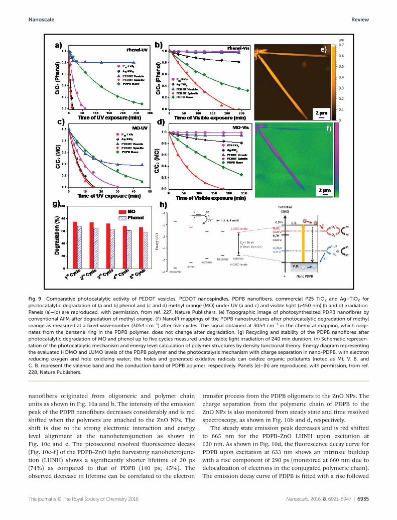
sufficiently stable and efficient for practical use have not yetbeen realized. CPNs provided attractive advantages includinghigh conductivity, good electrochemical activity, large specificsurface area, and short and direct pathways for charge trans-port, which increases the energy conversion performance.Recently, Ghosh et al. demonstrated that CPN based photo-catalysts (visible light-activated catalysts) may become asuseful as inorganic semiconductor catalysts in ultraviolet lightand also offer intriguing opportunities for future researchbecause of their responses to visible light. PEDOT nano-structures, having a narrow band gap (E = 1.69 eV) and anexcellent ability to absorb light in the visible and near infraredregion, demonstrate unprecedented photocatalytic activitiesfor water treatment without the assistance of sacrificialreagents or noble metal co-catalysts and have turned out to bebetter than TiO2 as the benchmark catalyst.227 The first experi-mental evidence of a visible light responsive photocatalyticactivity of poly(diphenylbutadiyne) (PDPB) nanofibers byphotoirradiation for water depollution has been reported.228 Ithas to be noted that the photocatalytic activity of PEDOTnanospindles has been found to be even higher than PDPBnanofibers under UV and visible light for phenol and MOdegradation (Fig. 9); 100% of phenol is degraded with PEDOTnanospindles after 240 min irradiation under visible light,while only 64% of phenol is degraded with PDPB. The novelCPN based photocatalysts are very stable with cycling and canbe reused without an appreciable loss of activity. The key tothe success of efficient solar energy conversion is the develop-ment of high performance materials having a well matchedphotoabsorption with the solar spectrum (visible light-harvest-ing capability), efficient photoexcited charge separation toprevent electron–hole recombination and an adequate energyof charges that carry out the photodegradation of dyes andother toxic molecules.
The integration of a semiconductor nanocrystal with anarrow band gap at CP heterojunctions has been shown to bean effective means of promoting charge carrier separation andimproving visible-light activity. However, the reported photo-conversion efficiency is small.229–231 As the interfacial area iscritical in achieving a favorable charge separation, it is essen-tial to incorporate nanoscale units in the heterojunctions.Hence, designing heterostructures with the appropriate mor-phological orientation and band position of the semiconduc-tor and the polymer unit is challenging. Very recently, Sardaret al. reported the formation of a unique nanoheterojunctionusing PDPB nanofibers with ZnO NPs to explore the effectivecharge separation from the polymer to the semiconductornanocrystals.232 There is very limited direct experimental evi-dence to establish the photoinduced charge transfer mechan-ism at the heterostructure interface. By virtue of having theintrinsic photoluminescence (PL) of ZnO from defect stateemission as well as CP from different oligomeric and poly-meric chains, a deep understanding of the interfacial carrierdynamics at the nanoheterojunction has been unraveled bysteady state and ultrafast spectroscopic studies, suggesting theco-sensitization of ZnO NPs by multiple states of polymer
Review Nanoscale
6934 | Nanoscale, 2016, 8, 6921–6947 This journal is © The Royal Society of Chemistry 2016
nanofibers originated from oligomeric and polymer chainunits as shown in Fig. 10a and b. The intensity of the emissionpeak of the PDPB nanofibers decreases considerably and is redshifted when the polymers are attached to the ZnO NPs. Theshift is due to the strong electronic interaction and energylevel alignment at the nanoheterojunction as shown inFig. 10c and e. The picosecond resolved fluorescence decays(Fig. 10c–f ) of the PDPB–ZnO light harvesting nanoheterojunc-tion (LHNH) shows a significantly shorter lifetime of 30 ps(74%) as compared to that of PDPB (140 ps; 45%). Theobserved decrease in lifetime can be correlated to the electron
transfer process from the PDPB oligomers to the ZnO NPs. Thecharge separation from the polymeric chain of PDPB to theZnO NPs is also monitored from steady state and time resolvedspectroscopy, as shown in Fig. 10b and d, respectively.
The steady state emission peak decreases and is red shiftedto 665 nm for the PDPB–ZnO LHNH upon excitation at620 nm. As shown in Fig. 10d, the fluorescence decay curve forPDPB upon excitation at 633 nm shows an intrinsic buildupwith a rise component of 290 ps (monitored at 660 nm due todelocalization of electrons in the conjugated polymeric chain).The emission decay curve of PDPB is fitted with a rise followed
Fig. 9 Comparative photocatalytic activity of PEDOT vesicles, PEDOT nanospindles, PDPB nanofibers, commercial P25 TiO2 and Ag–TiO2 forphotocatalytic degradation of (a and b) phenol and (c and d) methyl orange (MO) under UV (a and c) and visible light (>450 nm) (b and d) irradiation.Panels (a)–(d) are reproduced, with permission, from ref. 227, Nature Publishers. (e) Topographic image of photosynthesized PDPB nanofibres byconventional AFM after degradation of methyl orange. (f ) NanoIR mappings of the PDPB nanostructures after photocatalytic degradation of methylorange as measured at a fixed wavenumber (3054 cm−1) after five cycles. The signal obtained at 3054 cm−1 in the chemical mapping, which origi-nates from the benzene ring in the PDPB polymer, does not change after degradation. (g) Recycling and stability of the PDPB nanofibres afterphotocatalytic degradation of MO and phenol up to five cycles measured under visible light irradiation of 240 min duration. (h) Schematic represen-tation of the photocatalytic mechanism and energy level calculation of polymer structures by density functional theory. Energy diagram representingthe evaluated HOMO and LUMO levels of the PDPB polymer and the photocatalysis mechanism with charge separation in nano-PDPB, with electronreducing oxygen and hole oxidizing water; the holes and generated oxidative radicals can oxidize organic pollutants (noted as M); V. B. andC. B. represent the valence band and the conduction band of PDPB polymer, respectively. Panels (e)–(h) are reproduced, with permission, from ref.228, Nature Publishers.
Nanoscale Review
This journal is © The Royal Society of Chemistry 2016 Nanoscale, 2016, 8, 6921–6947 | 6935
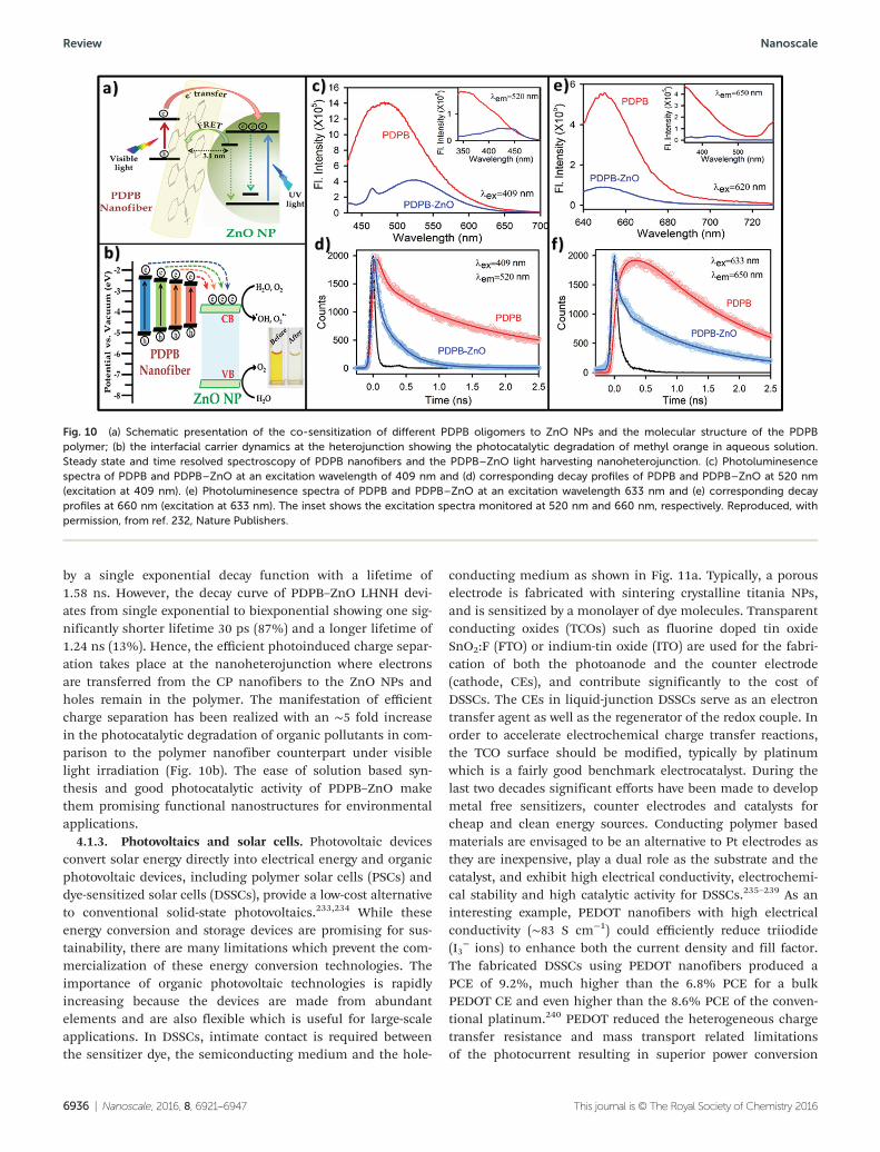
by a single exponential decay function with a lifetime of1.58 ns. However, the decay curve of PDPB–ZnO LHNH devi-ates from single exponential to biexponential showing one sig-nificantly shorter lifetime 30 ps (87%) and a longer lifetime of1.24 ns (13%). Hence, the efficient photoinduced charge separ-ation takes place at the nanoheterojunction where electronsare transferred from the CP nanofibers to the ZnO NPs andholes remain in the polymer. The manifestation of efficientcharge separation has been realized with an ∼5 fold increasein the photocatalytic degradation of organic pollutants in com-parison to the polymer nanofiber counterpart under visiblelight irradiation (Fig. 10b). The ease of solution based syn-thesis and good photocatalytic activity of PDPB–ZnO makethem promising functional nanostructures for environmentalapplications.
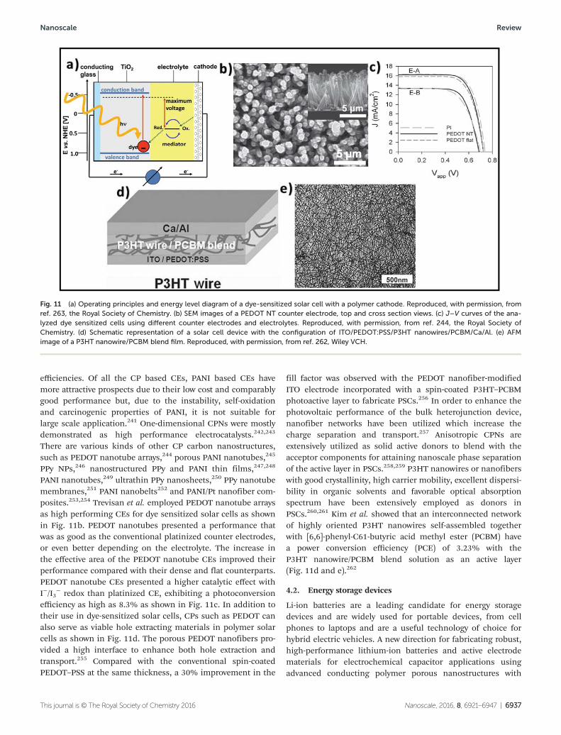
4.1.3. Photovoltaics and solar cells. Photovoltaic devicesconvert solar energy directly into electrical energy and organicphotovoltaic devices, including polymer solar cells (PSCs) anddye-sensitized solar cells (DSSCs), provide a low-cost alternativeto conventional solid-state photovoltaics.233,234 While theseenergy conversion and storage devices are promising for sus-tainability, there are many limitations which prevent the com-mercialization of these energy conversion technologies. Theimportance of organic photovoltaic technologies is rapidlyincreasing because the devices are made from abundantelements and are also flexible which is useful for large-scaleapplications. In DSSCs, intimate contact is required betweenthe sensitizer dye, the semiconducting medium and the hole-
conducting medium as shown in Fig. 11a. Typically, a porouselectrode is fabricated with sintering crystalline titania NPs,and is sensitized by a monolayer of dye molecules. Transparentconducting oxides (TCOs) such as fluorine doped tin oxideSnO2:F (FTO) or indium-tin oxide (ITO) are used for the fabri-cation of both the photoanode and the counter electrode(cathode, CEs), and contribute significantly to the cost ofDSSCs. The CEs in liquid-junction DSSCs serve as an electrontransfer agent as well as the regenerator of the redox couple. Inorder to accelerate electrochemical charge transfer reactions,the TCO surface should be modified, typically by platinumwhich is a fairly good benchmark electrocatalyst. During thelast two decades significant efforts have been made to developmetal free sensitizers, counter electrodes and catalysts forcheap and clean energy sources. Conducting polymer basedmaterials are envisaged to be an alternative to Pt electrodes asthey are inexpensive, play a dual role as the substrate and thecatalyst, and exhibit high electrical conductivity, electrochemi-cal stability and high catalytic activity for DSSCs.235–239 As aninteresting example, PEDOT nanofibers with high electricalconductivity (∼83 S cm−1) could efficiently reduce triiodide(I3
− ions) to enhance both the current density and fill factor.The fabricated DSSCs using PEDOT nanofibers produced aPCE of 9.2%, much higher than the 6.8% PCE for a bulkPEDOT CE and even higher than the 8.6% PCE of the conven-tional platinum.240 PEDOT reduced the heterogeneous chargetransfer resistance and mass transport related limitationsof the photocurrent resulting in superior power conversion
Fig. 10 (a) Schematic presentation of the co-sensitization of different PDPB oligomers to ZnO NPs and the molecular structure of the PDPBpolymer; (b) the interfacial carrier dynamics at the heterojunction showing the photocatalytic degradation of methyl orange in aqueous solution.Steady state and time resolved spectroscopy of PDPB nanofibers and the PDPB–ZnO light harvesting nanoheterojunction. (c) Photoluminesencespectra of PDPB and PDPB–ZnO at an excitation wavelength of 409 nm and (d) corresponding decay profiles of PDPB and PDPB–ZnO at 520 nm(excitation at 409 nm). (e) Photoluminesence spectra of PDPB and PDPB–ZnO at an excitation wavelength 633 nm and (e) corresponding decayprofiles at 660 nm (excitation at 633 nm). The inset shows the excitation spectra monitored at 520 nm and 660 nm, respectively. Reproduced, withpermission, from ref. 232, Nature Publishers.
Review Nanoscale
6936 | Nanoscale, 2016, 8, 6921–6947 This journal is © The Royal Society of Chemistry 2016
efficiencies. Of all the CP based CEs, PANI based CEs havemore attractive prospects due to their low cost and comparablygood performance but, due to the instability, self-oxidationand carcinogenic properties of PANI, it is not suitable forlarge scale application.241 One-dimensional CPNs were mostlydemonstrated as high performance electrocatalysts.242,243
There are various kinds of other CP carbon nanostructures,such as PEDOT nanotube arrays,244 porous PANI nanotubes,245
PPy NPs,246 nanostructured PPy and PANI thin films,247,248
PANI nanotubes,249 ultrathin PPy nanosheets,250 PPy nanotubemembranes,251 PANI nanobelts252 and PANI/Pt nanofiber com-posites.253,254 Trevisan et al. employed PEDOT nanotube arraysas high performing CEs for dye sensitized solar cells as shownin Fig. 11b. PEDOT nanotubes presented a performance thatwas as good as the conventional platinized counter electrodes,or even better depending on the electrolyte. The increase inthe effective area of the PEDOT nanotube CEs improved theirperformance compared with their dense and flat counterparts.PEDOT nanotube CEs presented a higher catalytic effect withI−/I3
− redox than platinized CE, exhibiting a photoconversionefficiency as high as 8.3% as shown in Fig. 11c. In addition totheir use in dye-sensitized solar cells, CPs such as PEDOT canalso serve as viable hole extracting materials in polymer solarcells as shown in Fig. 11d. The porous PEDOT nanofibers pro-vided a high interface to enhance both hole extraction andtransport.255 Compared with the conventional spin-coatedPEDOT–PSS at the same thickness, a 30% improvement in the
fill factor was observed with the PEDOT nanofiber-modifiedITO electrode incorporated with a spin-coated P3HT–PCBMphotoactive layer to fabricate PSCs.256 In order to enhance thephotovoltaic performance of the bulk heterojunction device,nanofiber networks have been utilized which increase thecharge separation and transport.257 Anisotropic CPNs areextensively utilized as solid active donors to blend with theacceptor components for attaining nanoscale phase separationof the active layer in PSCs.258,259 P3HT nanowires or nanofiberswith good crystallinity, high carrier mobility, excellent dispersi-bility in organic solvents and favorable optical absorptionspectrum have been extensively employed as donors inPSCs.260,261 Kim et al. showed that an interconnected networkof highly oriented P3HT nanowires self-assembled togetherwith [6,6]-phenyl-C61-butyric acid methyl ester (PCBM) havea power conversion efficiency (PCE) of 3.23% with theP3HT nanowire/PCBM blend solution as an active layer(Fig. 11d and e).262
4.2. Energy storage devices
Li-ion batteries are a leading candidate for energy storagedevices and are widely used for portable devices, from cellphones to laptops and are a useful technology of choice forhybrid electric vehicles. A new direction for fabricating robust,high-performance lithium-ion batteries and active electrodematerials for electrochemical capacitor applications usingadvanced conducting polymer porous nanostructures with
Fig. 11 (a) Operating principles and energy level diagram of a dye-sensitized solar cell with a polymer cathode. Reproduced, with permission, fromref. 263, the Royal Society of Chemistry. (b) SEM images of a PEDOT NT counter electrode, top and cross section views. (c) J–V curves of the ana-lyzed dye sensitized cells using different counter electrodes and electrolytes. Reproduced, with permission, from ref. 244, the Royal Society ofChemistry. (d) Schematic representation of a solar cell device with the configuration of ITO/PEDOT:PSS/P3HT nanowires/PCBM/Ca/Al. (e) AFMimage of a P3HT nanowire/PCBM blend film. Reproduced, with permission, from ref. 262, Wiley VCH.
Nanoscale Review
This journal is © The Royal Society of Chemistry 2016 Nanoscale, 2016, 8, 6921–6947 | 6937
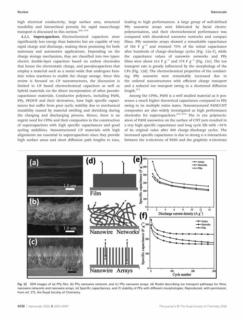
high electrical conductivity, large surface area, structuraltunability and hierarchical porosity for rapid mass/chargetransport is discussed in this section.264–270
4.2.1. Supercapacitors. Electrochemical capacitors storesignificantly less energy than batteries but are capable of veryrapid charge and discharge, making them promising for bothstationary and automotive applications. Depending on thecharge storage mechanism, they are classified into two types:electric double-layer capacitors based on carbon electrodesthat house the electrostatic charge, and pseodocapacitors thatemploy a material such as a metal oxide that undergoes Fara-daic redox reactions to enable the charge storage. Since thisreview is focused on CP nanostructures, the discussion islimited to CP based electrochemical capacitors as well ashybrid materials via the direct incorporation of other pseudo-capacitance materials. Conductive polymers, including PANI,PPy, PEDOT and their derivatives, have high specific capaci-tances but suffer from poor cyclic stability due to mechanicalinstability caused by material swelling and shrinking duringthe charging and discharging process. Hence, there is anurgent need for CPNs and their composites in the constructionof supercapacitors with high specific capacitances and goodcycling stabilities. Nanostructured CP materials with highalignments are essential in supercapacitors since they providehigh surface areas and short diffusion path lengths to ions,
leading to high performances. A large group of well-definedPPy nanowire arrays were fabricated by facial electro-polymerisation, and their electrochemical performance wascompared with disordered nanowire networks and compactfilms. PPy nanowire arrays showed a remarkable capacitanceof 566 F g−1 and retained 70% of the initial capacitanceafter hundreds of charge–discharge cycles (Fig. 12a–f ), whilethe capacitance values of nanowire networks and PPyfilms were about 414 F g−1 and 378 F g−1 (Fig. 12e). The iontransport rate is greatly influenced by the morphology of theCPs (Fig. 12d). The electrochemical properties of the conduct-ing PPy nanowire were remarkably increased due tothe ordered nanostructures with efficient charge transportand a reduced ion transport owing to a shortened diffusionlength.271
Among the CPNs, PANI is a well studied material as it pos-sesses a much higher theoretical capacitance compared to PPyowing to its multiple redox states. Nanostructured PANI/CNTcomposites are also widely investigated as high performanceelectrodes for supercapacitors.272–274 The in situ polymeriz-ation of PANI nanowires on the surface of CNT yarn resulted ina very high specific capacitance and long cycle life with ∼91%of its original value after 800 charge–discharge cycles. Theincreased specific capacitance is due to strong π–π interactionsbetween the π-electrons of PANI and the graphitic π-electrons
Fig. 12 SEM images of (a) PPy film, (b) PPy nanowire network, and (c) PPy nanowire arrays. (d) Model describing ion transport pathways for films,nanowire networks and nanowire arrays. (e) Specific capacitances, and (f ) stability of PPy with different morphologies. Reproduced, with permission,from ref. 271, the Royal Society of Chemistry.
Review Nanoscale
6938 | Nanoscale, 2016, 8, 6921–6947 This journal is © The Royal Society of Chemistry 2016
of CNTs and is responsible for the enhanced charge trans-fer.272 Meng et al.273 developed a flexible paper-like supercapa-citor assembled from PANI-coated CNT networks. The specificcapacitance of this flexible supercapacitor is 332 F g−1 at1 A g−1. The advantage of CPNs is that the density of the totaldevice is low (1.18 g cm−3), resulting in a low weight for theelectrode with an outstanding flexibility, making it surpass thecurrent commercial supercapacitor. Wei, Han and colleaguesinvestigated a hierarchical nanocomposite of PANI nanowirearrays on graphene oxide sheets which exhibited a highspecific capacitance of 227 F g−1 at 2 A g−1 and a long cycle lifewith ∼92% capacitance retention after 2000 cycles comparedto pure PANI (∼74% capacitance retention).275 3D porousreduced graphene oxide supported PANI nanowires displaybetter supercapacitive performances in terms of the specificcapacitance (∼1024 F g−1 with good stability over 5000 cycles).It is considered that this excellent supercapacitor performanceis mainly due to active PANI nanofibers with a large specificsurface area and the unique 3D structure of the graphenebackbone offering facile conducting pathways for chargetransportation.276
4.2.2. Lithium ion battery electrodes. Li-ion batteries areparticularly interesting due to their relatively high energy den-sities compared to other types of batteries, but a major con-straint is the intrinsic diffusivity of lithium ions. In thisregard, nanomaterials with shorter diffusion paths are chosenwhich would increase the rate of lithium insertion orreduction and enhance electron transport as well as provide ahigh surface area. Silicon is considered one of the most promis-ing anode materials for high-performance Li-ion batteries.However, a dramatic volume change (∼300%) during fullcharge/discharge cycling, led to a severe capacity decay andpoor cycling stability for intimate contact with the electrolyte.Liu et al. reported a new direction for fabricating robust, high-performance lithium-ion batteries using three-dimensional(3D) ternary silicon NP/CP/carbon nanotube hybrid anodematerials for Li-ion batteries (Fig. 13a).277 Fig. 13a and b showthe discharge capacity of the ternary electrode and the first dis-charge capacity of the ternary electrode reached as high as∼3600 mA h g−1, approximately 10 times higher that of thecommercial graphite anode (372 mA h g−1). The ternary elec-trode achieved a stable discharge capacity of 1600 mA h g−1
over 1000 cycles with a capacity retention of ∼86% and theCoulombic efficiency increased to 99% and stabilized at∼99.5% in the subsequent cycles. The improved cycling per-formance and life-span of the electrode could be attributed tothe stabilized Si NPs which were well confined within the 3Dconductive framework that was composed of both 3D PPyhydrogels and SWCNTs. Fig. 13c shows the SEM image of thecycled ternary electrode which suggests the polymeric coatingon the Si NP surface was well maintained after the cycling testas confirmed in Fig. 13d. Overall, the cycling performance ofthe ternary electrode is significantly improved compared topreviously reported Si anodes due to the enhanced electronicconductivity, and shortened pathway length for ion transportcontributed from CP.
Taken together, designing and fabricating novel CPN basedelectrode materials can overcome current limitations. Xia et al.developed the synthesis of Co3O4–PANI core–shell nanowirearrays and the composite anodes exhibited a superior Li-ionstorage capability compared to the bare Co3O4 nanowirearrays.278 Liang et al. developed PPy nanotubes as conductivematrices to support sulfur cathodes in lithium–sulfur bat-teries.279 Further, surface chemical modification or molecular-level modification can be applied to enhance the mechanicaland electrical properties of CPNs along with surface passiva-tion to avoid undesirable reactions in order to improve theperformance of nanostructured conductive polymer-basedelectrodes.280
5. Origin of excitingmultifunctionality in CPnanostructures
The controlled synthesis of nanometer-scale conducting poly-mers is a fascinating objective in materials science. CP NPs areformed by self-assembling the as-designed molecular buildingblocks via the weaker intermolecular interactions betweenadjacent molecules, such as hydrogen bonding, π–π stackingand hydrophobic interactions. This section highlights the fun-damental understanding of the relationship between structuralproperties and the electrochemical as well as optoelectronicperformances of CPs in the nano regime. A dramatic changein various physicochemical properties, such as electrical,thermal, mechanical, electrical and optical, has been realizedin nanoscale dimensions compared to the bulk counter-parts.281 The performance of the CPN is expected to be betterin comparison to the bulk counterpart, since polymer nano-structures have light weights, high surface areas, unique opto-electronic properties, high conductivity, stability, flexibilityand processibility.12–14 The CPNs show high electrical conduc-tivity and high electrochemical activity, as compared to theirmacrogranular structure or self-supporting films.282,283
For example, the electrical conductivity of the PDPB nano-structures obtained by gamma irradiation is 0.13 S cm−1,which is several orders of magnitude higher than the conduc-tivity of bulk polyacetylene, 10−11 S cm−1.284 Morever, due tothe air sensitivity of bulk polyacetylene, the stability of thebulk polymer films in air is limited. The conductivity of PDPBnanofibers is found to increase slightly with the decrease ofthe diameter of the nanofibers. The improved ordering of theunidirectional polymer chains resulted in a greatly increasedconductivity. As another example, PANI NPs with a smallersize of 4 nm and high crystallinity demonstrated a conductivityof 85 S cm−1 due to the highly compact and ordered structureof the PANI chains.285 The star-shaped PANI showed higherelectrical conductivity than the corresponding homopolymers,originating from the three-dimensional and nanostructuredmorphologies of the star-shaped polymers, which allowssufficient overlapping of π-orbitals.286 Several studies report a
Nanoscale Review
This journal is © The Royal Society of Chemistry 2016 Nanoscale, 2016, 8, 6921–6947 | 6939
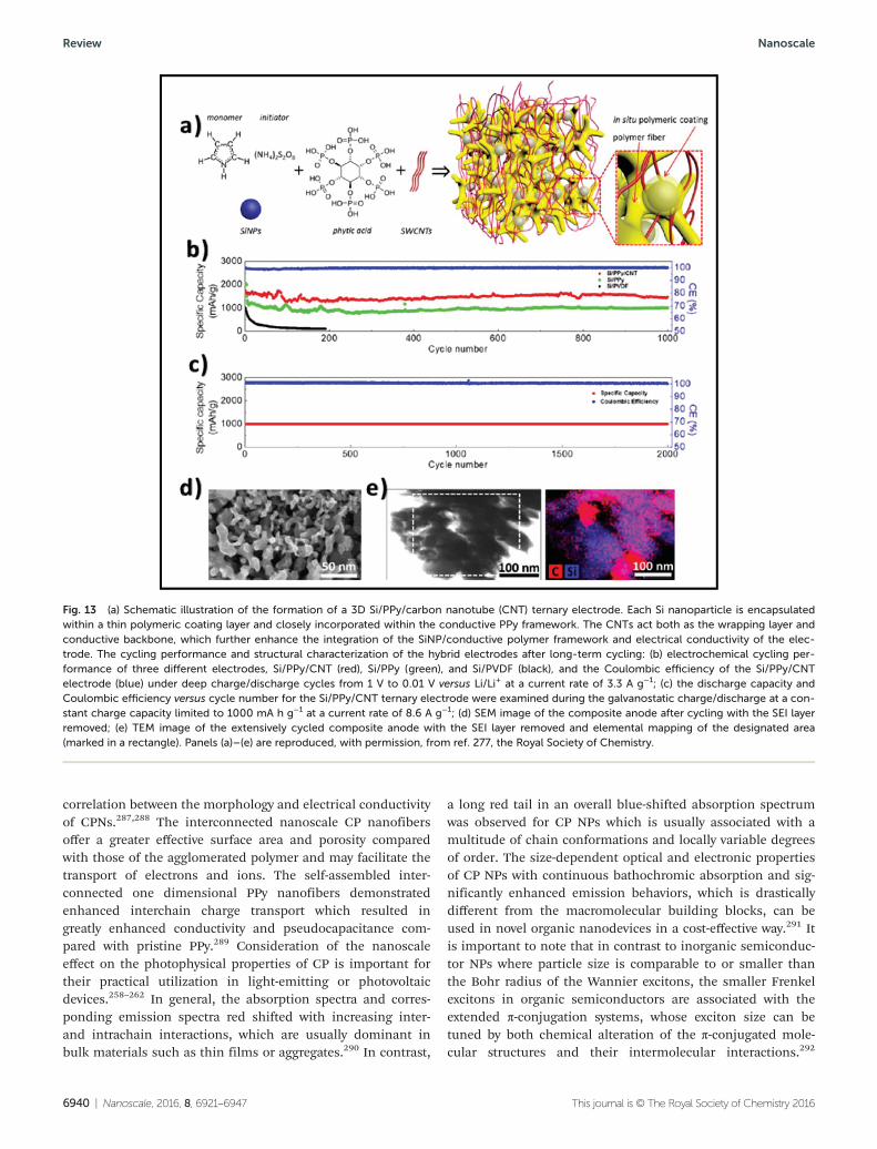
correlation between the morphology and electrical conductivityof CPNs.287,288 The interconnected nanoscale CP nanofibersoffer a greater effective surface area and porosity comparedwith those of the agglomerated polymer and may facilitate thetransport of electrons and ions. The self-assembled inter-connected one dimensional PPy nanofibers demonstratedenhanced interchain charge transport which resulted ingreatly enhanced conductivity and pseudocapacitance com-pared with pristine PPy.289 Consideration of the nanoscaleeffect on the photophysical properties of CP is important fortheir practical utilization in light-emitting or photovoltaicdevices.258–262 In general, the absorption spectra and corres-ponding emission spectra red shifted with increasing inter-and intrachain interactions, which are usually dominant inbulk materials such as thin films or aggregates.290 In contrast,
a long red tail in an overall blue-shifted absorption spectrumwas observed for CP NPs which is usually associated with amultitude of chain conformations and locally variable degreesof order. The size-dependent optical and electronic propertiesof CP NPs with continuous bathochromic absorption and sig-nificantly enhanced emission behaviors, which is drasticallydifferent from the macromolecular building blocks, can beused in novel organic nanodevices in a cost-effective way.291 Itis important to note that in contrast to inorganic semiconduc-tor NPs where particle size is comparable to or smaller thanthe Bohr radius of the Wannier excitons, the smaller Frenkelexcitons in organic semiconductors are associated with theextended π-conjugation systems, whose exciton size can betuned by both chemical alteration of the π-conjugated mole-cular structures and their intermolecular interactions.292
Fig. 13 (a) Schematic illustration of the formation of a 3D Si/PPy/carbon nanotube (CNT) ternary electrode. Each Si nanoparticle is encapsulatedwithin a thin polymeric coating layer and closely incorporated within the conductive PPy framework. The CNTs act both as the wrapping layer andconductive backbone, which further enhance the integration of the SiNP/conductive polymer framework and electrical conductivity of the elec-trode. The cycling performance and structural characterization of the hybrid electrodes after long-term cycling: (b) electrochemical cycling per-formance of three different electrodes, Si/PPy/CNT (red), Si/PPy (green), and Si/PVDF (black), and the Coulombic efficiency of the Si/PPy/CNTelectrode (blue) under deep charge/discharge cycles from 1 V to 0.01 V versus Li/Li+ at a current rate of 3.3 A g−1; (c) the discharge capacity andCoulombic efficiency versus cycle number for the Si/PPy/CNT ternary electrode were examined during the galvanostatic charge/discharge at a con-stant charge capacity limited to 1000 mA h g−1 at a current rate of 8.6 A g−1; (d) SEM image of the composite anode after cycling with the SEI layerremoved; (e) TEM image of the extensively cycled composite anode with the SEI layer removed and elemental mapping of the designated area(marked in a rectangle). Panels (a)–(e) are reproduced, with permission, from ref. 277, the Royal Society of Chemistry.
Review Nanoscale
6940 | Nanoscale, 2016, 8, 6921–6947 This journal is © The Royal Society of Chemistry 2016
Notably, exciton transfer in nanofiber aggregates occurredmainly through interchain hops from chromophores on theaggregate surface to the aggregate core, due to the higher levelof crystallinity, which is important for organic electronic appli-cations.293 Many efforts were devoted to the morphologycontrol of CPs which enhanced both the light absorption andthe charge transport to achieve high efficiency photovoltaicdevices at low cost. For example, P3HT nanowires or nanofi-bers have been mostly explored as donors in PSCs becausethey combine the advantages of an ideal size (ca.10–50 nmdiameters, which are within the exciton diffusion lengthrange), a good crystallinity, a high carrier mobility, an excellentdispersibility in organic solvents and a favorable opticalabsorption spectrum.294 A notable example is that the mor-phology and size of CPNs have a close relationship with theoxidation level and conjugation length.295 It has been reportedthat carrier mobility and concentration, the ordered structureof polymer chains and the oxidation level of PEDOT contributegreatly to the controlled enhancement of the thermoelectricperformance of the PEDOT nanostructures.296 The electricalconductivity and the power factor follow the same sequence ofbulk PEDOT < globular nanoparticle < nanorod or ellipsoidalnanoparticle < nanotube < nanofiber. Another example is CPhydrogels with unique 3D hierarchical porous nanostructures,which are suitable as active electrode materials, resulting inhigh electrical conductivity for rapid mass/charge transport forelectrochemical capacitors or as functional binder materialsfor high-energy lithium-ion batteries.209 Hence, comparedwith their bulk forms, nanostructured conductive polymersexhibit improved physicochemical properties and shortenedpathways for charge, mass or ion transport, which is ideal forapplications in energy-related fields.
6. Conclusions and future directions
To conclude, we summarized the fabrication techniques aswell as the characterization of nanoscale conducting polymerstructures for solar light harvesting and energy storage appli-cations. CPNs demonstrate excellent mobility, solubility, smallband gaps, a large absorption enhancement and the possi-bility to tailor the morphology make them superlative candi-dates for various applications in the energy domain. Moreover,CPNs have the unique feature of hybridization with otherclasses of nanostructures (for example, inorganic semiconduc-tors and metals) to generate novel hybrid nanocompositeswith multifunctional properties. The characterization of CPnanostructures has also progressed significantly and is nowpushing the limits of nanomaterial characterization tech-niques. Using integrated characterization techniques such ascombined STM with TEM, AFM with FTIR and combined fluo-rescence spectroscopy with electron microscopy techniques,may help in understanding advanced nanomaterials and theirdevelopment towards applications. The possibility of combin-ing the electrocatalytic properties of metal nanostructures andCPs with significant photochemical properties opens a range
of novel applications as well as the need for understanding therelationship between these properties. The application ofCPNs in the fields of electrocatalysis, energy storage and con-version has been presented. CPNs offer unique and tremen-dous opportunities in solar light harvesting and furtherimprovements to fabrication techniques may contribute to theimplementation of future generations’ solar cells and devices.For visible light active photocatalysis using hybrid composites,structural and band gap engineering are both necessary tofurther improve the light absorption from the solar spectrum.Future study and development are required for efficientsolar cell performances. CPNs have successfully been used ascounter electrodes with a cobalt based redox shuttle to give abetter result than the benchmark platinized cathode. Theunderstanding of electrochemical charge transfer at thesurface is key to optimization of these solar cells. Additionally,the mechanism of electrocatalysis on the CP surface is still notexplored well in the literature. Many fundamental questionsremain to be answered about how nanoscale conducting poly-mers significantly differ from those in the bulk. How does thechemical reactivity of materials differ at the nanolevel and howdo the ionic and electronic conductivities couple and behaveat the nanolevel? How can the different properties of CPs andtheir composites be used to increase the power and energyefficiencies of devices? Moreover, a significant problem to besolved is the development of a low-cost, large scale synthesis ofCP based nanocomposites for their use in practical battery,fuel and solar cell systems.
Abbreviations
CP Conducting polymerNPs NanoparticlesCPNs Conducting polymer nanostructuresPEDOT Poly(3,4-ethylenedioxythiophene)PPy PolypyrrolePANI PolyanilinePTh PolythiopheneP3HT Poly(3-hexylthiophene)PDPB Poly diphenylbutadiynePPV Poly(p-phenylenevinylene)PMT Poly(3-methylthiophene)AAO Anodic aluminum oxidePTM Particle track-etched membranesAFM Atomic force microscopyLHNH Light harvesting nanoheterojunctionPSCs Polymer solar cellsDSSCs Dye-sensitized solar cellsTCO Conducting transparent oxidesITO Indium-tin oxideCE Counter electrodePEMFCs Polymer electrolyte membrane fuel cellsCNx Carbon nitrideDMFCs Direct methanol fuel cells
Nanoscale Review
This journal is © The Royal Society of Chemistry 2016 Nanoscale, 2016, 8, 6921–6947 | 6941
DEFCs Direct ethanol fuel cellsLIBs Lithium-ion batteries
Acknowledgements
The authors acknowledge Director, CSIR-CGCRI for his kindpermission to publish the work. One of the authors (SG) isthankful to Council of Scientific & Industrial Research (CSIR),India, for providing CSIR-Senior Research Associate (Scientists’Pool Scheme) award.
Notes and references
1 S. Gunes, H. Neugebauer and N. S. Sariciftci, Chem. Rev.,2007, 107, 1324–1338.
2 G. Inzelt, J. Solid State Electrochem., 2011, 15, 1711–1718.3 S. Kirchmeyer and K. Reuter, J. Mater. Chem., 2005, 15,
2077–2088.4 C. Li, H. Bai and G. Shi, Chem. Soc. Rev., 2009, 38, 2397–
2409.5 S. Bhadra, D. Khastgir, N. K. Singha and J. H. Lee, Prog.
Polym. Sci., 2009, 34, 783–810.6 J. Wang, D. Zhang, D. Zhang and Y. Wang, Mater. Sci. Eng.
B, 2006, 134, 9–19.7 J. Wang and D. Zhang, Adv. Polym. Technol., 2013, 32,
E323–E368.8 S. Günes, H. Neugebauer and N. S. Sariciftci, Chem. Rev.,
2007, 107, 1324–1338.9 D. W. Hatchett and M. Josowicz, Chem. Rev., 2008, 108,
746–769.10 D. T. McQuade, A. E. Pullen and T. M. Swager, Chem. Rev.,
2000, 100, 2537–2574.11 J. Janata and M. Josowicz, Nat. Mater., 2003, 2, 19–24.12 Y. Shi, L. Peng, Y. Ding, Y. Zhao and G. Yu, Chem. Soc.
Rev., 2015, 44, 6684–6696.13 J. Pecher and S. Mecking, Chem. Rev., 2010, 110, 6260–
6279.14 F. S. Kim, G. Ren and S. A. Jenekhe, Chem. Mater., 2011,
23, 682–732.15 T. Ito, H. Shirakawa and S. Ikeda, J. Polym. Sci., 1974, 12,
11–20.16 H. Shirakawa, E. Louis, A. MacDiarmid, C. Chiang and
A. Heeger, J. Chem. Soc., Chem. Commun., 1977, 16, 578.17 A. J. Heeger, Angew, Chem., Int. Ed., 2001, 40, 2591–2611.18 L. Pan, H. Qiu, C. Dou, Y. Li, L. Pu, J. Xu and Y. Shi,
Int. J. Mol. Sci., 2010, 11, 2636–2657.19 C. R. Martin, Acc. Chem. Res., 1995, 28, 61–68.20 S. Il Cho and S. B. Lee, Acc. Chem. Res., 2008, 41, 699–707.21 C. R. Martin, Science, 1994, 266, 1961–1966.22 C. R. Martin, R. Parthasarathy and V. Menon, Electrochim.
Acta, 1994, 39, 1309–1313.23 W. Lee and S. J. Park, Chem. Rev., 2014, 114, 7487–7556.24 M. Treuba, M. A. L. Montero and J. Rieumont, Electrochim.
Acta, 2004, 49, 4341–4349.
25 M. S. Cho, H. J. Choi and W. S. Ahn, Langmuir, 2004, 20,202–207.
26 Z. Zhang, J. Sui, L. Zhang, M. Wan, Y. Wei and L. Yu, Adv.Mater., 2005, 17, 2854–2857.
27 P. J. Kulesza, M. Chojak, K. Miecznikowski, A. Lewera,M. M. Malik and A. Kuhn, Electrochem. Commun., 2002, 4,510–526.
28 J. Steinmetz, S. Kwon, H. J. Lee, E. Abou-Hamad,R. Almaric, C. GozeBac, H. Kim and Y. W. Park, Chem.Phys. Lett., 2006, 431, 139–144.
29 K. Jackowska, T. Aleksander, A. T. Bieguński andM. Tagowska, J. Solid State Electrochem., 2008, 12, 437–443.
30 M. G. Han and S. H. Foulger, Chem. Commun., 2005, 3092.31 J. Fei, Y. Cui, X. Yan, Y. Yang, K. Wang and J. Li, ACS
Nano, 2009, 3, 3714–3718.32 S. De Vito and C. R. Martin, Chem. Mater., 1998, 10, 1738–
1741.33 A. Rahman and M. K. Sanyal, Adv. Mater., 2007, 19, 3956–
3960.34 G. A. O’Brien, A. J. Quinn, D. Iacopino, N. Pauget and
G. Redmond, J. Mater. Chem., 2006, 16, 3237S.35 D. Bearden, J. P. Cannon and S. A. Gold, Macromolecules,
2011, 44, 2200–2205.36 R. Liu, J. Duay and S. B. Lee, ACS Nano, 2011, 5, 5608–
5619.37 C. G. Wu and T. Bein, Science, 1994, 264, 1757–1759.38 X. Zhang, A. G. MacDiarmid and S. K. Manohar, Chem.
Commun., 2005, 5328–5330.39 L. J. Pan, L. Pu, Y. Shi, S. Y. Song, Z. Xu, R. Zhang and
Y. D. Zheng, Adv. Mater., 2007, 19, 461–464.40 T. Y. Dai and Y. Lu, Macromol. Rapid Commun., 2007, 28,
629–633.41 G. C. Li, C. Q. Zhang, H. R. Peng and K. Z. Chen, Macro-
mol. Rapid Commun., 2009, 30, 1841–1845.42 J. Jang and H. Yoon, Langmuir, 2005, 21, 11484–11489.43 J. Jang, J. Bae and E. Park, Adv. Mater., 2006, 18, 354–358.44 H. Yoon, M. Choi, K. J. Lee and J. Jang, Macromol. Res.,
2008, 16, 85–102.45 P. Anilkumar and M. Jayakannan, Macromolecules, 2008,
41, 7706–7715.46 B. H. Jones, K. Y. Cheng, R. J. Holmes and T. P. Lodge,
Macromolecules, 2012, 45, 599–601.47 K. J. Ahn, Y. Lee, H. Choi, M. S. Kim, K. Im, S. Noh and
H. Yoon, Sci. Rep., 2015, 5, 14097.48 L. Xia, Z. Wei and M. Wan, J. Colloid Interface Sci., 2010,
341, 1–11.49 P. Anilkumar and M. Jayakannan, J. Phys. Chem. B, 2010,
114, 728–736.50 P. Anilkumar and M. Jayakannan, J. Phys. Chem. B, 2009,
113, 11614–11624.51 M. X. Wan, Y. Q. Shen and J. Huang, Chinese Patent,
981099165, 1998.52 X. Zhang, J. Zhang, W. Song and Z. Kiu, J. Phys. Chem. B,
2006, 110, 1158–1165.53 M. J. Antony and M. Jayakannan, J. Phys. Chem. B, 2007,
111, 12772–12780.
Review Nanoscale
6942 | Nanoscale, 2016, 8, 6921–6947 This journal is © The Royal Society of Chemistry 2016
54 M. Shirakawa, N. Fujita and S. A. Shinkai, J. Am. Chem.Soc., 2005, 127, 4164–4165.
55 J. R. Néabo, S. Rondeau-Gagné, C. Vigier-Carrière andJ. F. Morin, Langmuir, 2013, 29, 3446–3452.
56 G. Li, Y. Li, H. Li, H. Peng and K. Chen, Macromolecules,2011, 44, 9319–9323.
57 Z. Liu, X. Y. Zhang, S. Poyraz, S. P. Surwad andS. K. Manohar, J. Am. Chem. Soc., 2010, 132, 13158–13159.
58 J. R. Néabo, K. I. S. Tohoundjona and J. F. Morin, Org.Lett., 2011, 13, 1358–1361.
59 B. S. Forney, C. Baguenard and C. A. Guymon, Chem.Mater., 2013, 25, 2950–2960.
60 J. F. Hulvat and S. I. Stupp, Angew. Chem., Int. Ed., 2003,42, 778–781.
61 J. F. Hulvat and S. I. Stupp, Adv. Mater., 2004, 16, 589–592.62 G. Surendran, M. S. Tokumoto, E. Pena dos Santos,
H. Remita, L. Ramos, P. J. Kooyman, C. V. Santilli,C. Bourgaux, P. Dieudonné and E. Prouzet, Chem. Mater.,2005, 17, 1505–1514.
63 S. Ghosh, H. Remita, L. Ramos, A. Dazzi, A. Deniset-Besseau, P. Beaunier, F. Goubard, P.-H. Aubert andS. Remita, New J. Chem., 2014, 38, 1106–1115.
64 N. K. Sadanandhan, S. J. Devaki, R. K. Narayanan andM. Cheriyathuchenaaramvalli, ACS Appl. Mater. Interfaces,2015, 7, 18028–18037.
65 H. Komiyama, M. Komura, Y. Akimoto, K. Kamata andT. Iyoda, Chem. Mater., 2015, 27, 4972–4982.
66 J. D. Tovar, B. M. Rabatic and S. I. Stupp, Small, 2007,3(12), 2024–2028.
67 L. Hsu, G. L. Cvetanovich and S. I. Stupp, J. Am. Chem.Soc., 2008, 130, 3892–3389.
68 R. Nagarajan, J. Kumar, F. Bruno, L. A. Samuelson andR. Nagarajan, Macromolecules, 2008, 41, 3049–3052.
69 Z. Niu, J. Liu, L. A. Lee, M. A. Bruckman, D. Zhao,G. Koley and Q. Wang, Nano Lett., 2007, 7, 3729–3733.
70 Z. G. Wang, Q. Liu and B. Ding, Chem. Mater., 2014, 26,3364–3367.
71 R. Hassanien, M. Al-Hinai, S. A. F. Al-Said, R. Little,L. Ŝiller, N. G. Wright, A. Houlton and B. R. Horrocks, ACSNano, 2010, 4, 2149–2159.
72 H. K. Moon, H. J. Kim, N. H. Kim and Y. J. Roh, Nanosci.Nanotechnol., 2010, 10, 3180–3184.
73 Y. Ma, J. Zhang, G. Zhang and H. He, J. Am. Chem. Soc.,2004, 126, 7097–7101.
74 S. Richardson-Burns, J. L. Hendricks, L. K. Povlich,B. Foster, D. Kim and D. C. Martin, Biomater., 2007, 28,1539–1552.
75 V. Rumbau, J. A. Pomposo, A. Eleta, J. Rodriguez,H. Grande, D. Mecerreyes and E. Ochoteco, Biomacro-molecules, 2007, 2, 315–317.
76 Z. W. Niu, M. A. Bruckman, S. Q. Li, L. A. Lee, B. Lee,S. V. Pingali, P. Thiyagarajan and Q. Wang, Langmuir,2007, 23, 6719–6724.
77 D. Pahovnik, E. Žagar, K. Kogej, J. Vohlídal and M. Žigon,Eur. Polym. J., 2013, 49, 1381–1390.
78 G. Li, Y. Li, Y. Li, H. Peng and K. Chen, Macromolecules,2011, 44, 9319–9323.
79 Y. Zhu, D. Hu, M. Wan, L. Jiang and Y. Wei, Adv. Mater.,2007, 19, 2092–2096.
80 H. W. Park, T. Kim, J. Huh, M. Kang, J. E. Lee andH. Yoon, ACS Nano, 2012, 6, 7624–7633.
81 M. Wan, Adv. Mater., 2008, 20, 2926–2932.82 Q. Zhao, R. Jamal, L. Zhang, M. C. Wang and T. Abdiryim,
Nanoscale Res. Lett., 2014, 9, 557–565.83 H. D. Tran, J. M. D’Arcy, Y. Wang, P. J. Beltramo,
V. A. Strong and R. B. Kaner, J. Mater. Chem., 2011, 21,3534–3550.
84 H. J. Ding, J. Y. Shen, M. X. Wan and Z. J. Chen, Macromol.Chem. Phys., 2008, 209, 864–871.
85 H. W. Park, T. Kim, J. Huh, M. Kang, J. E. Lee andH. Yoon, ACS Nano, 2012, 6, 7624–7633.
86 J. Liu, Y. Lin, L. Liang, J. A. Voigt, D. L. Huber, Z. R. Tian,E. Coker, B. Mckenzie and M. J. Mcdermott, Chem. – Eur.J., 2003, 9, 605–611.
87 J. Wang, S. Chan, R. R. Carlson, Y. Luo, G. L. Ge,R. S. Ries, J. R. Heath and H. R. Tseng, Nano Lett., 2004, 4,1693–1697.
88 K. Ramanathan, M. A. Bangar, M. Yun, W. Chen,A. Mulchandani and N. V. Myung, Nano Lett., 2004, 4,1237–1239.
89 L. J. Zhang, Y. Z. Long, Z. J. Chen and M. X. Wan, Adv.Funct. Mater., 2004, 14, 693–698.
90 H. J. Ding, J. Y. Shen, M. X. Wan and Z. J. Chen, Macromol.Chem. Phys., 2008, 209, 864–871.
91 H. J. Ding, M. X. Wan and Y. Wei, Adv. Mater., 2007, 19,465–469.
92 H. J. Ding, Y. Z. Long, J. Y. Shen and M. X. Wan, J. Phys.Chem. B, 2010, 114, 115–119.
93 P. Dallasa and V. Georgakilas, Adv. Colloid Interface Sci.,2015, 224, 46–61.
94 C. Yuan, L. Zhang, L. Hou, J. Lin and G. Pang, RSC Adv.,2014, 4, 24773–24776.
95 H. Ma, Y. Luo, S. Yang, Y. Li, F. Cao and J. Gong, J. Phys.Chem. C, 2011, 115, 12048–12053.
96 T. Li, Z. Qin, B. Liang, F. Tian, J. Zhao, N. Liu and M. Zhu,Electrochim. Acta, 2015, 177, 343–351.
97 J. Huang, S. Virji, B. H. Weiller and R. B. Kaner, J. Am.Chem. Soc., 2003, 125, 314–315.
98 Y. Haldorai, T. Zong and J.-J. Shim, Mater. Chem. Phys.,2011, 127, 385–390.
99 J. M. Du, J. L. Zhang, B. X. Han, Z. M. Liu and M. X. Wan,Synth. Met., 2005, 155, 523–526.
100 N. Nuraje, K. Su, N.-l. Yang and H. Matsui, ACS Nano,2008, 2, 502–506.
101 K. Su, N. Nuraje, L. Zhang, I. W. Chu, R. M. Peetz,H. Matsui and N. L. Yang, Adv. Mater., 2007, 19, 669–672.
102 H. Y. Ma, Y. Q. Luo, S. Yang, Y. Li, F. Cao and J. Gong,J. Phys. Chem. C, 2011, 115, 12048–12053.
103 Z. M. Huang, Y. Z. Zhang, M. Kotaki and S. Ramakrishna,Compos. Sci. Technol., 2003, 63, 2223–2253.
Nanoscale Review
This journal is © The Royal Society of Chemistry 2016 Nanoscale, 2016, 8, 6921–6947 | 6943
104 A. G. MacDiarmid, W. E. Jones Jr., I. D. Norris, J. Gao,A. T. Johnson Jr., N. J. Pinto, J. Hone, B. Han, F. K. Ko,H. Okuzaki and M. Llaguno, Synth. Met., 2001, 119, 27–30.
105 I. S. Chronakis, S. Grapenson and A. Jakob, Polymer, 2006,47, 1597–1603.
106 J. Choi, J. Lee, J. Choi, D. Jung and S. E. Shim, Synth. Met.,2010, 160, 1415–1421.
107 Z. Q. Feng, J. Wu, W. Cho, M. K. Leach, E. W. Franzd,Y. I. Naimd, Z.-Z. Gug, J. M. Corey and D. C. Martin,Polymer, 2013, 54, 702–708.
108 J. W. T. Spinks and R. J. Woods, An Introduction toRadiation Chemistry, Wiley, New York, 3rd edn, 1990.
109 S. Ghosh, A. Datta and A. Saha, Colloids Surf., A, 2009,355, 130–138.
110 S. K. Pillalamarri, F. D. Blum, A. T. Tokuhiro, J. G. Storyand M. F. Bertino, Radiolytic Chem. Mater., 2005, 17, 227–229.
111 M. R. Karim, C. J. Lee and M. S. Lee, Polym. Adv. Technol.,2007, 18, 916–920.
112 Z. Huang, L. Shi, Q. Zhu, J. Zou and T. Chen,Chin. J. Chem. Phys., 2010, 23, 701–706.
113 Y. Lattach, A. D. Besseau, J.-M. Guigner and S. Remita,Radiat. Phys. Chem., 2013, 82, 44–53.
114 Y. Lattach, C. Coletta, S. Ghosh and S. Remita, Chem-PhysChem, 2014, 15, 208–218.
115 Z. Cui, C. Coletta, R. Rebois, S. Baiz, M. Gervais,F. Goubard, P.-H. Aubert, A. Dazzi and S. Remita, Radiat.Phys. Chem., 2016, 119, 157–166.
116 Z. Cui, C. Coletta, A. Dazzi, P. Lefrançois, M. Gervais,S. Néron and S. Remita, Langmuir, 2014, 30, 14086–14094.
117 C. Coletta, Z. Cui, P. Archirel, P. Pernot, J. L. Marignierand S. Remita, J. Phys. Chem. B, 2015, 119, 5282–5298.
118 S. A. Krupenkin, T. Taylor, A. Fratzl and P. Aizenberg,J. Science, 2007, 315, 487–490.
119 R. A. Green, S. Baek, L. A. Poole-Warren and P. J. Martens,Sci. Technol. Adv. Mater., 2010, 11, 014107–014120.
120 N. Mano, J. E. Yoo, J. Tarver, Y.-L. Loo and A. Heller, J. Am.Chem. Soc., 2007, 129, 7006–7007.
121 T. Dai and Y. Jia, Polymer, 2011, 52, 2550–2558.122 L. Pan, G. Yu, D. Zhai, H. R. Lee, W. Zhao, N. Liu,
H. Wang, B. C. Tee, Y. Shi, Y. Cui and Z. Bao, Proc. Natl.Acad. Sci. U. S. A., 2012, 109, 9287–9292.
123 L. W. Xia, R. Xie, X. J. Ju, W. Wang, Q. Chen andL. Y. Chu, Nat. Commun., 2013, 4, 2226–2236.
124 R. Temmer, R. Kiefer, A. Aabloo and T. Tamm, J. Mater.Chem. A, 2013, 1, 15216–15219.
125 P. Y. Chen, M. D. Nasim Hyder, D. Mackanic,N. M. D. Courchesne, J. Qi, M. T. Klug, A. M. Belcher andP. T. Hammond, Adv. Mater., 2014, 26, 5101–5107.
126 Y. Zhao, B. Liu, L. Pan and G. Yu, Energy Environ. Sci.,2013, 6, 2856–2870.
127 D. Mawad, E. Stewart, D. L. Officer, T. Romeo, P. Wagner,K. Wagner and G. G. Wallace, Adv. Funct. Mater., 2012, 22,2692–2699.
128 R. Du and X. T. Zhang, Acta Phys.-Chim. Sin., 2012, 28,2305–2314.
129 L. Chen, B. Suhk, M. Nishino, J. P. Gong and Y. Osada,Macromolecules, 2000, 33, 1232–1236.
130 P. Marcasuzaa, S. Reynaud, F. Ehrenfeld, A. Khoukh andD. J. Chitosan, Biomacromolecules, 2010, 11, 1684–1691.
131 T. Dai, X. Jiang, S. Hua, X. Wang and Y. Lu, Chem.Commun., 2008, 4279–4281.
132 L. Pan, G. Yub, D. Zhaia, H. R. Lee, W. Zhao, N. Liue,H. Wang, B. C.-K. Tee, Y. Shia, Y. Cui and Z. Bao, Proc.Natl. Acad. Sci. U. S. A., 2012, 109, 9287–9292.
133 R. Du, Y. Xu, Y. Luo, X. Zhang, J. Zhang and G. Yan,Chem. Commun., 2011, 47, 6287–6289.
134 D. Wei, X. Lin, L. Li, S. Liang, S. Shang, M. C. Yuen andY. Yu, Soft Matter, 2013, 9, 2832–2836.
135 K. H. Kim, M. Vural and M. F. Islam, Adv. Mater., 2011,23, 2865–2869.
136 J. Biener, M. Stadermann, M. Suss, M. A. Worsley,M. M. Biener, K. A. Rose and T. F. Baumann, EnergyEnviron. Sci., 2011, 4, 656–667.
137 X. T. Zhang, D. W. Chang, J. R. Liu and Y. J. Luo, J. Mater.Chem., 2010, 20, 5080–5085.
138 X. T. Zhang, C. Y. Li and Y. J. Luo, Langmuir, 2011, 27,1915–1923.
139 Y. Xu, Z. Sui, B. Xu, H. Duan and X. Zhang, J. Mater.Chem., 2012, 22, 8579–8584.
140 Y. Lu, W. He, T. Cao, H. Guo, Y. Zhang, Q. Li, Z. Shao,Y. Cui and X. Zhang, Sci. Rep., 2014, 4, 5792–5799.
141 C. Yang, H. Wei, L. Guan, J. Guo, Y. Wang, X. Yan,X. Zhang, S. Wei and Z. Guo, J. Mater. Chem. A, 2015, 3,14929–14941.
142 S. Ghosh, A. Hussein Khan and S. Acharya, J. Phys. Chem.C, 2012, 116, 6022–6033.
143 S. Ghosh, D. Ghosh, P. Kumar Bag, S. C. Bhattacharya andA. Saha, Nanoscale, 2011, 3, 1139–1148.
144 R. Gangopadhyay and A. De, Chem. Mater., 2000, 12, 608–622.
145 R. J. Tseng, J. Huang, J. Ouyang, R. B. Kaner and Y. Yang,Nano Lett., 2005, 5, 1077–1080.
146 L. Yang, Z. Zhang, G. Nie, C. Wang and X. Lu, J. Mater.Chem. A, 2015, 3, 83–86.
147 Y. Liu, N. Lu, S. Poyraz, X. Wang, Y. Yu, J. Scott, J. Smith,M. J. Kim and X. Zhang, Nanoscale, 2013, 5, 3872–3879.
148 J.-H. Choi, K.-W. Park, H.-K. Lee, Y.-M. Kim, J.-S. Lee andY.-E. Sung, Electrochim. Acta, 2003, 48, 2781–2789.
149 Z. Zhang, F. Wang, F. Chen and G. Shi, Mater. Lett., 2006,60, 1039–1042.
150 G. W. Lu, C. Li, J. Y. Shen, Z. J. Chen and G. Q. Shi,J. Phys. Chem. C, 2007, 111, 5926–5931.
151 M. Chang, T. Kim, H. W. Park, M. Kang, E. Reichmanisand H. Yoon, ACS Appl. Mater. Interfaces, 2012, 4, 4357–4365.
152 A. P. O’Mullane, S. E. Dale, J. V. Macpherson andP. R. Unwin, Chem. Commun., 2004, 1606–1607.
153 Y. Gao, C. A. Chen, H. M. Gau, J. A. Bailey, E. Akhadov,D. Williams and H. L. Wang, Chem. Mater., 2008, 20,2839–2844.
Review Nanoscale
6944 | Nanoscale, 2016, 8, 6921–6947 This journal is © The Royal Society of Chemistry 2016
154 H. H. Shih, D. Williams, N. H. Mack and H. L. Wang,Macromolecules, 2009, 42, 14–16.
155 M. Grzeszczuk and P. Poks, Electrochim. Acta, 2000, 45,4171–4177.
156 H. Q. Cao, C. Y. Tie, Z. Xu, J. M. Hong and H. Sang, Appl.Phys. Lett., 2001, 78, 1592–1594.
157 A. Drury, S. Chaure, M. Kröll, V. Nicolosi, N. Chaure andW. J. Blau, Chem. Mater., 2007, 19, 4252–4258.
158 S. Mondal, U. Rana and S. Malik, ACS Appl. Mater. Inter-faces, 2015, 7, 10457–10465.
159 S. Dutt, P. Felix Siril, V. Sharma and S. Periasamy, NewJ. Chem., 2015, 39, 902–908.
160 S. Fujii, S. Matsuzawa, H. Hamasaki, Y. Nakamura,A. Bouleghlimat and N. J. Buurma, Langmuir, 2012, 28,2436–2447.
161 S. G. Song, C. Satheeshkumar, J. Park, J. Ahn,T. Premkumar, Y. Lee and C. Song, Macromolecules, 2014,47, 6566–6571.
162 S. Fujii, S. Matsuzawa, Y. Nakamura, A. O. T. Teratani,K. Akamatsu, T. Tsuruoka and H. Nawafune, Langmuir,2010, 26, 6230–6239.
163 S. S. Kumar, C. S. Kumar, J. Mathiyarasu and K. L. Phani,Langmuir, 2007, 23, 3401–3408.
164 A. Soni, C. Mouli Pandey, S. Solanki and G. Sumana, RSCAdv., 2015, 5, 45767–45774.
165 U. Mandi, A. S. Roy, B. Banerjee and S. K. Manirul Islam,RSC Adv., 2014, 4, 42670–42681.
166 X. Li, Y. Gao, J. Gong, L. Zhang and L. Qu, J. Phys. Chem.C, 2009, 113, 69–73.
167 M. Choudhary, S. K. Shukla, A. Taher, S. Siwal andK. Mallick, ACS Sustainable Chem. Eng., 2014, 2, 2852–2858.
168 J. Han, J. Ma and Z. Ma, Electrochem. Commun., 2013, 33,47–50.
169 E. Park, O. S. Kwon, S. J. Park, J. S. Lee, S. You and J. Jang,J. Mater. Chem., 2012, 22, 1521–1526.
170 W. Jia, L. Su and Y. Lei, Biosens. Bioelectron., 2011, 30,158–164.
171 Z. Liu, Q. Rong, Z. Ma and H. Han, Biosens. Bioelectron.,2015, 65, 307–313.
172 P. Boomi, H. G. Prabu and J. Mathiyarasu, Eur. J. Med.Chem., 2014, 72, 18–25.
173 M. Bhaumik, J. Hyoung, R. Choi, R. I. McCrindle andA. Maity, J. Colloid Interface Sci., 2014, 425, 75–82.
174 Y. Qu and X. Duan, Chem. Soc. Rev., 2013, 42, 2568–2580.175 Y. Wang, Q. Wang, X. Zhan, F. Wang, M. Safdar and J. He,
Nanoscale, 2013, 5, 8326–8339.176 P. Reiss, E. Couderc, J. De Girolamo and A. Pron, Nano-
scale, 2011, 3, 446–489.177 T. Zhou, S. Tan, Y. Guo, L. Ma, M. Gan, H. Wang, X. Sun
and H. Wang, J. Alloys Compd., 2015, 652, 358–363.178 A. Petrella, M. Tamborra, M. L. Curri, P. Cosma,
M. Striccoli, P. D. Cozzoli and A. Agostiano, J. Phys. Chem.B, 2005, 109, 1554–1562.
179 Q. Luo, L. Bao, D. Wang, X. Li and J. An, J. Phys. Chem. C,2012, 116, 25806–25815.
180 Y.-W. Su, W.-H. Lin, Y.-J. Hsu and K.-H. Wei, Small, 2014,10, 4427–4442.
181 M. Ates, Prog. Org. Coat., 2011, 71, 1–10.182 P. Taranekar, X. Fan and R. Advincula, Langmuir, 2002, 18,
7943–7952.183 S. Pruneanu, S. A. F. Al-Said, L. Dong, T. A. Hollis,
M. A. Galindo, N. G. Wright, A. Houton andB. R. Horrocks, Adv. Funct. Mater., 2008, 18, 2444–2454.
184 L. S. C. Pingree, O. G. Reid and D. S. Ginger, Adv. Mater.,2009, 21, 19–28.
185 J. N. Barisci, R. Stella, G. M. Spinks and G. G. Wallace,Synth. Met., 2001, 124, 407–414.
186 K. Takami, J. Mizuno, M. Akai-kasaya, A. Saito, M. Aonoand Y. Kuwahara, J. Phys. Chem. B, 2004, 108, 16353–16356.
187 Y. Martin, D. W. Abraham and H. L. Wickramasinghe,Appl. Phys. Lett., 1998, 52, 1103–1105.
188 O. A. Semenikhin, L. Jiang, T. Iyoda, K. Hashimoto andA. Fujishima, J. Phys. Chem., 1996, 100, 18603–18606.
189 K. D. O’Neil, B. Shaw and O. A. Semenikhin, J. Phys.Chem. B, 2007, 111, 9253–9269.
190 R. J. Tseng, J. Huang, J. Ouyang, R. B. Kaner and Y. Yang,Nano Lett., 2005, 5, 1077–1080.
191 H. Kobayashi, S. Hirata and M. Vacha, J. Phys. Chem. Lett.,2013, 4, 2591–2596.
192 S. Ghosh, L. Ramos, A. Dazzi, A. Deniset-Besseau,S. Remita, P. Beaunier and H. Remita, New J. Chem., 2015,39, 8311–8320.
193 J. Liu, B. Wei, J. D. Sloppy, L. Ouyang, C. Ni andD. C. Martin, ACS Macro Lett., 2015, 4, 897–900.
194 Y. Lattach, C. Coletta, S. Ghosh and S. Remita, Chem-PhysChem, 2014, 15, 208–218.
195 Z. Cui, C. Coletta, A. Dazzi, P. Lefrancois, M. Gervais,S. Neron and S. Remita, Langmuir, 2014, 30, 14086–14094.
196 Z. Cui, C. Coletta, R. Rebois, S. Baiz, M. Gervais,F. Goubard, P.-H. Aubert, A. Dazzi and S. Remita, Radiat.Phys. Chem., 2016, 119, 157–166.
197 S. Admassie, O. Inganäs, W. Mammob, E. Perzon andM. R. Andersson, Synth. Met., 2006, 156, 614–623.
198 X. Wu, K. Liu, L. Lu, Q. Han, F. Bei, X. Yang, X. Wang,Q. Wu and W. Zhu, J. Phys. Chem. C, 2013, 117, 9477–9484.
199 S. J. Higgins, K. V. Lovell, R. M. Gamini Rajapaksea,N. M. Walsby and M. Wals, J. Mater. Chem., 2003, 13,2485–2489.
200 E. Barsoukov and J. R. Macdonald, Impedance Spec-troscopy: Theory, Experiment, and Applications, Wiley Inter-science, Hoboken, NJ, 2005.
201 M. D. Levi, Y. Gofer, D. Aurbach and A. Berlin, Electro-chim. Acta, 2004, 49, 433–444.
202 M. R. Abidian and D. C. Martin, Adv. Funct. Mater., 2009,19, 573–585.
203 B. W. Johnson, D. C. Read, P. Christensen, A. Mamnet andR. D. Armstrong, J. Electroanal. Chem., 1994, 364, 103–109.
204 J. R. Macdonald, Electrochim. Acta, 1990, 35, 1483–1492.205 D. A. Harrington and B. E. Conway, Electrochim. Acta,
1987, 32, 1703–1721.
Nanoscale Review
This journal is © The Royal Society of Chemistry 2016 Nanoscale, 2016, 8, 6921–6947 | 6945
206 M. R. Abidian, J. M. Corey, D. R. Kipke and D. C. Martin,Small, 2010, 6, 421–429.
207 M. R. Abidian and D. C. Martin, Biomaterials, 2008, 29,1273–1283.
208 Z. Yin and Q. Zheng, Adv. Energy Mater., 2012, 2, 179–218.209 L. Ye, S. Peng and G. Yu, Nanoscale, 2015, 7, 12796–12806.210 Y. Shi, L. Peng, Y. Ding, Y. Zhao and G. Yu, Chem. Soc.
Rev., 2015, 44, 6684–6696.211 X. Yuan, X. L. Ding, C.-Y. Wang and Z. F. Ma, Energy
Environ. Sci., 2013, 6, 1105–1124.212 K. Cong, M. Ritter, S. Stumpf, B. Schrçter, U. S. Schubert
and A. Ignaszak, Electroanalysis, 2014, 26, 2567–2573.213 S. Ghosh, A.-L. Teillout, D. Floresyona, P. de Oliveira,
A. Hagège and H. Remita, Int. J. Hydrogen Energy, 2015,40, 4951–4959.
214 B. Rajesh, K. R. Thampi, J. M. Bonard, H. J. Mathieu,N. Xanthopoulos and B. Viswanathan, Electrochem. Solid-State Lett., 2004, 7, A404–A407.
215 Z. Chen, L. Xu, W. Li, M. Waje and Y. Yan, Nanotechnology,2006, 17, 5254–5259.
216 Q. Zhou, C. M. Li, J. Li and J. Lu, J. Phys. Chem. C, 2008,112, 18578–18583.
217 C. Jiang and X. Lin, J. Power Sources, 2007, 164, 49–55.218 B. Rajesh, B. Thampi, K. R. Bonard, J. M. Mathieu,
H. J. Xanthopoulos and N. B. Viswanathan, Chem.Commun., 2003, 2022–2023.
219 Y. Ma, S. Jiang, G. Jian, H. Tao, L. Yu, X. Wang, X. Wang,J. Zhu, Z. Hu and Y. Chen, Energy Environ. Sci., 2009, 2,224–229.
220 B. Rajesh, K. R. Thampi, J. M. Bonard, A. J. McEvoy,N. Xanthopoulos, H. J. Mathieu and B. Viswanathan,J. Power Sources, 2004, 133, 155–161.
221 T. Maiyalagan, J. Power Sources, 2008, 179, 443–450.222 J. Schneider, M. Matsuoka, M. Takeuchi, J. Zhang,
Y. Horiuchi, M. Anpo and D. W. Bahnemann, Chem. Rev.,2014, 114, 9919–9986.
223 X. Chen, L. Liu, P. Y. Yu and S. S. Mao, Science, 2011, 331,746–750.
224 S. Linic, P. Christopher and D. B. Ingram, Nat. Mater.,2011, 10, 911–921.
225 Y. Lu, H. Yu, S. Chen, X. Quan and H. Zhao, Environ. Sci.Technol., 2012, 46, 1724–1730.
226 L. Li, J. Yan, T. Wang, Z.-J. Zhao, J. Zhang, J. Gong andN. Guan, Nat. Commun., 2015, 6, 5881–5891.
227 S. Ghosh, K. A. Natalie, S. Remita, L. Ramos, F. Goubard,P.-H. Aubert, A. Dazzi, A. Deniset-Besseau and H. Remita,Sci. Rep., 2015, 5, 18002.
228 S. Ghosh, K. A. Natalie, L. Ramos, S. Remita, A. Dazzi,A. Deniset-Besseau, F. Goubard, P.-H. Aubert andH. Remita, Nat. Mater., 2015, 14, 505–511.
229 G. Liao, S. Chen, X. Quan, H. Chen and Y. Zhang, Environ.Sci. Technol., 2010, 44, 3481–3485.
230 Q. Luo, L. Bao, D. Wang, X. Li and J. An, J. Phys. Chem. C,2012, 116, 25806–25815.
231 Z. Pei, L. Ding, M. Lu, Z. Fan, S. Weng, J. Hu and P. Liu,J. Phys. Chem. C, 2014, 118, 9570–9577.
232 S. Sardar, P. Kar, H. Remita, B. Liu, P. Lemmens, S. K. Paland S. Ghosh, Sci. Rep., 2015, 5, 17313.
233 J. Roncali, Adv. Energy Mater., 2011, 1, 147–160.234 Z. He, B. Xiao, F. Liu, H. Wu, Y. Yang, S. Xiao, C. Wang,
T. P. Russell and Y. Cao, Nat. Photonics, 2012, 9, 174–179.235 H. Tian, Z. Yu, A. Hagfeldt, L. Kloo and L. Sun, J. Am.
Chem. Soc., 2011, 133, 9413–9422.236 B. E. Hardin, H. J. Snaith and M. D. McGehee, Nat. Photo-
nics, 2012, 6, 161–169.237 J.-H. Yum, E. Baranoff, F. Kessler, T. Moehl, S. Ahmad,
T. Bessho, A. Marchioro, E. Ghadiri, J.-E. Moser, C. Yi,M. K. Nazeeruddin and M. Gratzel, Nat. Commun., 2012, 3,631–639.
238 H. N. Tsao, J. Burschka, C. Yi, F. Kessler,M. K. Nazeeruddin and M. Gratzel, Energy Environ. Sci.,2011, 4, 4921–4924.
239 K. Saranya, Md. Rameez and A. Subramania, Eur. Polym.J., 2015, 66, 207–227.
240 T. H. Lee, K. Do, Y. W. Lee, S. S. Jeon, C. Kim, J. Ko andS. S. Im, J. Mater. Chem., 2012, 22, 21624–21629.
241 Q. Li, J. Wu, Q. Tang, Z. Lan, P. Li, J. Lin and L. Fan,Electrochem. Commun., 2008, 10, 1299–1302.
242 L. Zhao, Y. Li, Z. Liu and H. Shimizu, Chem. Mater., 2010,22, 5949–5956.
243 B. Fan, X. Mei, K. Sun and J. Ouyang, Appl. Phys. Lett.,2008, 93, 143103.
244 R. Trevisan, M. Döbbelin, P. P. Boix, E. M. Barea, R. Tena-Zaera, I. Mora-Seró and J. Bisquert, Adv. Energy Mater.,2011, 1, 781–784.
245 K.-H. Park, S. J. Kim, R. Gomes and A. Bhaumik, Chem.Eng. J., 2015, 260, 393–398.
246 J. Wu, Q. Li, L. Fan, Z. Lan, P. Li, J. Lin and S. Hao,J. Power Sources, 2008, 181, 172–176.
247 J. Xia, L. Chen and S. Yanagida, J. Mater. Chem., 2011, 21,4644–4649.
248 J. Zhang, T. Hreid, X. Li, W. Guo, L. Wang, X. Shi, H. Suand Z. Yuan, Electrochim. Acta, 2010, 55, 3664–3668.
249 Q. Qin and R. A. Zhang, Electrochim. Acta, 2013, 89, 726–731.
250 D. K. Hwang, D. Song, S. S. Jeon, T. H. Han, Y. S. Kangand S. S. Im, J. Mater. Chem. A, 2014, 2, 859–867.
251 T. Peng, W. Sun, C. Huang, W. Yu, B. Sebo, Z. Dai, S. Guoand X. Z. Zhao, ACS Appl. Mater. Interfaces, 2014, 6, 14–17.
252 Z. Lan, J. Wu, S. Gao, J. Lin, M. Huang and X. Chen,Polym. Adv. Technol., 2014, 25, 343–346.
253 Z. Tang, J. Wu, M. Zheng, Q. Tang, Q. Liu, J. Lin andJ. Wang, RSC Adv., 2012, 2, 4062–4064.
254 S. Guo, S. Dong and E. Wang, Small, 2009, 5, 1869–1876.255 J. H. Huang, Z. Y. Ho, D. Kekuda, C. W. Chu and K. C. Ho,
J. Phys. Chem. C, 2008, 112, 19125–19130.256 E. Nasybulin, S. Wei, M. Cox, I. Kymissis and K. Levon,
J. Phys. Chem. C, 2011, 115, 4307–4314.257 L. Li, D. L. Jacobs, Y. Che, H. Huang, B. R. Bunes, X. Yang
and L. Zang, Org. Electron., 2013, 14, 1383–1390.258 S. Berson, R. De Bettignies, S. Bailly and S. Guillerez, Adv.
Funct. Mater., 2007, 17, 1377–1384.
Review Nanoscale
6946 | Nanoscale, 2016, 8, 6921–6947 This journal is © The Royal Society of Chemistry 2016
259 T. Salim, S. Sun, L. H. Wong, L. Xi, Y. L. Foo andY. M. Lam, J. Phys. Chem. C, 2010, 114, 9459–9468.
260 G. Li, V. Shrotriya, Y. Yao, J. Huang and Y. Yang, J. Mater.Chem., 2007, 17, 3126–3140.
261 S. S. V. Bavel, E. Sourty, G. D. With and J. Loos, Nano Lett.,2009, 9, 507–513.
262 J. S. Kim, J. H. Lee, J. H. Park, C. Shim, M. Sim andK. Cho, Adv. Funct. Mater., 2011, 21, 480–486.
263 S. Ahmad, J.-H. Yum, Z. Xianxi, M. Graotzel, H. J. Buttand M. K. Nazeeruddin, J. Mater. Chem., 2010, 20, 1654–1658.
264 L. P. Soares, C. Checkles, Y. Zhao and G. Yu, Nano Lett.,2013, 13, 3414–3419.
265 B. Anothumakkoola, R. Sonia, S. N. Bhange andS. Kurungot, Energy Environ. Sci., 2015, 8, 1339–1347.
266 Q. Lu, Q. Zhao, H. Zhang, J. Li, X. Wang and F. Wang, ACSMacro Lett., 2013, 2, 92–95.
267 H. Wu, G. Yu, L. Pan, N. Liu, M. T. McDowell, Z. Bao andY. Cui, Nat. Commun., 2013, 4, 1943–1946.
268 T. Liu, L. Finn, M. Yu, H. Wang, T. Zhai, X. Lu, Y. Tongand Y. Li, Nano Lett., 2014, 14, 2522–2527.
269 Y. Zhao, B. Liu, L. Pan and G. Yu, Energy Environ. Sci.,2013, 6, 2856–2870.
270 Y. Shi, L. Peng and G. Yu, Nanoscale, 2015, 7, 12796–12806.
271 J. Y. Huang, K. Wang and Z. X. Wei, J. Mater. Chem., 2010,2, 1117–1121.
272 K. Wang, P. Zhao, X. Zhou, H. Wu and Z. Wei, J. Mater.Chem., 2011, 21, 16373–16378.
273 C. Meng, C. Liu, L. Chen, C. Hu and S. Fan, Nano Lett.,2010, 10, 4025–4031.
274 Z. Niu, P. Luan, Q. Shao, H. Dong, J. Li, J. Chen, D. Zhao,L. Cai, W. Zhou and X. Chen, Energy Environ. Sci., 2012, 5,8726–8733.
275 J. Xu, K. Wang, S. Z. Zu, B. H. Han and Z. Wei, ACS Nano,2010, 4, 5019–5026.
276 S. B. Kulkarni, U. M. Patil, I. Shackery, J. S. Sohn, S. Lee,B. Park and S. Jun, J. Mater. Chem. A, 2014, 2, 4989–4998.
277 B. Liu, P. Soares, C. Checkles, Y. Zhao and G. Yu, NanoLett., 2013, 13, 3414–3419.
278 X. Xia, D. Chao, X. Qi, Q. Xiong, Y. Zhang, J. Tu, H. Zhangand H. J. Fan, Nano Lett., 2013, 13, 4562–4568.
279 X. Liang, Y. Liu, Z. Wen, L. Huang, X. Wang andH. Zhang, J. Power Sources, 2011, 196, 6951–6955.
280 Y. Shi, L. Peng, Y. Ding, Y. Zhao and G. Yu, Chem. Soc.Rev., 2015, 44, 6684–6696.
281 F. S. Kim, G. Ren and S. A. Jenekhe, Chem. Mater., 2011,23, 682–732.
282 K. Ramanathan, M. A. Bangar, M. H. Yun, W. Chen,A. Mulchandani and N. V. Myung, Nano Lett., 2004, 4,1237–1239.
283 H. D. Tran, D. Li and R. B. Kaner, Adv. Mater., 2009, 21,1487–1499.
284 H. Nakanishi, H. Matsuda and M. Kato, Mol. Cryst. Liq.Cryst., 1984, 105, 77–88.
285 J. Jang, J. Ha and S. Kim, Macromol. Res., 2007, 15, 154–159.
286 B. Massoumi, N. Aalia and M. Jaymand, RSC Adv., 2015, 5,107680–107693.
287 W. Łużny and E. Bańka, Macromolecules, 2000, 33, 425–429.
288 W. Li, Q. Zhang, G. Zheng, Z. W. Seh, H. Yao and Y. Cui,Nano Lett., 2013, 13, 5534–5540.
289 Y. Wang, Y. Shi, L. Pan, Y. Ding, Y. Zhao, Y. Li, Y. Shi andG. Yu, Nano Lett., 2015, 15, 7736–7741.
290 B. J. Schwartz, Annu. Rev. Phys. Chem., 2003, 54, 141–172.
291 F. Wang, M.-Y. Han, K. Y. Mya, Y. Wang and Y.-H. Lai,J. Am. Chem. Soc., 2005, 127, 10350–10355.
292 D. Xiao, W. Yang, J. Yao, L. Xi, X. Yang and Z. Shuai,J. Am. Chem. Soc., 2004, 126, 15439–15444.
293 P. C. Tapping, S. N. Clafton, K. N. Schwarz, T. W. Kee andD. M. Huang, J. Phys. Chem. C, 2015, 119, 7047–7059.
294 B. Friedel, C. R. McNeill and N. C. Greenham, Chem.Mater., 2010, 22, 3389–3392.
295 H. Yoon, J.-Y. Hoon and J. Jang, Small, 2007, 3, 1774–1783.
296 X. Hu, G. Chen, X. Wang and H. Wang, J. Mater. Chem. A,2015, 3, 20896–20902.
Nanoscale Review
This journal is © The Royal Society of Chemistry 2016 Nanoscale, 2016, 8, 6921–6947 | 6947


![Lecture on Intrinsically conducting polymers on textiles [EN] · Conducting polymers • Intrinsically conducting polymers (ICPs) are π-conjugated organic polymers able to conduct](https://img.pdfslide.us/doc/110x75/5f07a9317e708231d41e19a9/lecture-on-intrinsically-conducting-polymers-on-textiles-en-conducting-polymers.jpg)