Embed Size (px)
Citation preview
Functionalization
DOI: 10.1002/smll.200500324
Metal Nanoparticles and Related Materials Supportedon Carbon Nanotubes: Methods and ApplicationsGregory G. Wildgoose, Craig E. Banks, and Richard G. Compton*
From the Contents
1. Introduction.............183
2. Methods ofFunctionalizing CNTswith MetalNanoparticles...........183
3. Applications of CNT-SupportedNanoparticles...........188
4. Summary and Outlook................................191
Keywords:· carbon nanotubes· catalysis· functionalization· nanoparticles· sensors
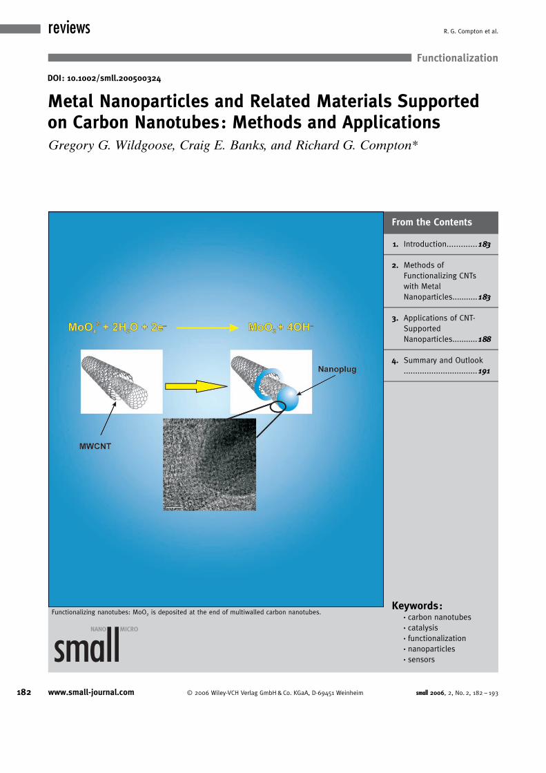
Functionalizing nanotubes: MoO2 is deposited at the end of multiwalled carbon nanotubes.
182 www.small-journal.com ! 2006 Wiley-VCH Verlag GmbH&Co. KGaA, D-69451 Weinheim small 2006, 2, No. 2, 182 – 193
reviews R. G. Compton et al.
Carbon nanotubes are one of the most intensively explored nanostructuredmaterials. In particular, carbon nanotubes are unique and ideal templatesonto which to immobilize nanoparticles allowing the construction ofdesigned nanoarchitectures that are extremely attractive as supports forheterogeneous catalysts, for use in fuel cells, and in related technologies thatexploit the inherent $smallness% and hollow characteristics of the nano-particles. Here we overview the recent developments in this area by exploringthe various techniques in which nanotubes can be functionalized with metalsand other nanoparticles and explore the diverse applications of the resultingmaterials.
1. Introduction
The applications and scope of carbon nanotubes (CNTs)have dramatically increased and continue to expand sincetheir rediscovery in 1991. Oberlin and Endo[1] reported in1976 that carbon fibers had been prepared with various ex-ternal shapes that contained a hollow tube with diametersranging from 20 to more than 500 ) along the fiber axis.They observed stacks of carbon layers, parallel to the fiberaxis, which where arranged in concentric sheets. They alsonoted that very small cementite crystals, typically about100 ) in diameter, were formed at the tip of the centraltube of each fiber.[1] In 1978, Wiles and Abrahamson firstmentioned carbon fibers down to 4 nm in diameter (namely,carbon nanotubes, although the term “nanotubes” originatesfrom the 1990s) found on a graphite electrode.[2] In theirpublication, Wiles and Abrahamson described a thick matof fine fibers and crystallites which they found on graphiteand carbon anodes following low-current arc operation innitrogen at atmospheric pressure. They observed fibersranging in diameter from �4 nm up to 100 nm with lengthsup to 15 micrometers, which also held many small crystallineparticles. Further details of the structure of the carbonfibers were presented at a conference in 1979,[3] which werethen republished elsewhere.[4] From their electron diffrac-tion study Abrahamson et al. reported that the fibers con-sisted of wrapped graphitic basal layers with a hollow core.Also they noted that the basal layer spacing was distortedfrom the normal graphitic spacing, and larger. Carbon nano-tubes were then reported by Iijima in 1991[5] and thenumber of publications each year utilizing carbon nanotubesescalates at a hugely increasing rate.
Carbon nanotubes have intrinsic properties, which in-clude, high surface area, unique physical properties andmorphology, high electrical conductivity, and their inherentsize and hollow geometry can make them extremely attrac-tive as supports for heterogeneous catalysts.[6–10]
A plethora of literature therefore exists on the function-alization of carbon nanotubes with metal particles. In thisReview, we critically overview literature reports of metalnanoparticles supported on carbon nanotubes and selective-ly explore their applications.
2. Methods of Functionalizing CNTs with MetalNanoparticles
There are many ingenious methods of depositing metalnanoparticles onto CNT substrates in the literature, each of-fering varying degrees of control of particle size and distri-bution along the CNT. In this section, we first review exam-ples where electrodeposition techniques have been used togreat advantage, before illustrating some interesting chemi-cal deposition methods where the resulting materials areused in electrochemical applications. Throughout, the sheervolume of material has required us to be highly selective inthe choice of illustrative material presented.
2.1. Electrochemical Methods
Considering the recent interest in the use of CNTs fromboth an electrochemical point of view and as metal nanopar-ticle catalyst supports, it is somewhat surprising to find sofew examples of electrochemically controlled metal nano-particle deposition on CNTs in the literature, and these arelimited to the noble metals Pd,[11–13] Pt,[11,14–17] Au,[11] Ag,[16,18]
and bimetallic Pt–Ru.[19] Nonetheless, electrochemistry is apowerful technique for the deposition of many metals and/or the surface modification of CNTs, being both rapid andfacile, and thus allowing the chemist to easily control thenucleation and growth of metal nanoparticles.[12, 13,16,17] Byvarying the deposition potential, substrate, and depositiontime one can control the size and distribution of metalnanoparticles. In particular, many of the imaginative meth-ods of decorating CNTs with metal nanoparticles involve te-dious and time-consuming treatments that allow impuritiesin the bath solutions to be incorporated either into the
[*] G. G. Wildgoose, Dr. C. E. Banks, Prof. R. G. ComptonPhysical and Theoretical Chemistry LaboratoryUniversity of Oxford, South Parks RoadOxford, OX1 3QZ (UK)Fax: (+44)1865-275-410E-mail: [email protected]
small 2006, 2, No. 2, 182 – 193 ! 2006 Wiley-VCH Verlag GmbH&Co. KGaA, D-69451 Weinheim 183
Functionalized Carbon Nanotubes
nanoparticles or onto the walls of the CNTs themselves,thus impairing the optical or catalytic properties of thenanoparticles.[17] Electrochemically deposited nanoparticles,particularly noble metals such as Pt or Pd, are often of veryhigh purity, are formed rapidly, and have good adhesion tothe CNT substrate.[17, 19]
One particularly elegant advantage of electrochemicaldeposition is illustrated by the recent work of Guo andLi.[13,17] Often for successful deposition of nanoparticlesonto CNT substrates the CNTs have to be first oxidativelytreated to introduce oxygen-containing functionalities suchas quinonyl, carboxyl, or hydroxyl groups to which themetal nanoparticle precursors can bind. This usually in-volves harsh treatments with concentrated mixtures ofstrong oxidizing acids, such as sulfuric and nitric acid, and/or ozonolysis, which may lead to severe damage to theCNTs. In their efforts to develop electrochemical methodsfor the deposition of Pt[17] and Pd[13] nanoparticles ontoCNTs, Guo and Li carried out a much gentler electrochemi-cal pretreatment to oxidize single-walled carbon nanotubes(SWCNTs), thus introducing the required functionality tothe SWCNTs without damaging them. Their simple three-step electrochemical method for depositing Pt or Pd nano-particles is shown schematically in Figure 1, and producesmetal nanoparticles �5 nm in diameter.[13, 17]
He et al. took advantage of the high purity of electro-chemically deposited nanoparticles to decorate CNTs withbimetallic Pt–Ru nanoparticles with diameters of 60–80 nm.[19] Again the multiwalled carbon nanotubes(MWCNTs) underwent an electrochemical oxidation pre-treatment before the deposition took place potentiostatical-ly at �0.25 V from a solution containing various concentra-tion ratios of ruthenium chloride and chloroplatinic acid in
0.5m H2SO4. This facile deposition method then allowed theauthors to investigate the effect of varying amounts of Ruin the Pt–Ru nanoparticles on their electrocatalytic activitytowards methanol oxidation. Ru is known to inhibit the poi-soning of Pt catalysts by adsorbed CO, formed as an inter-mediate in the methanol oxidation process, following a bi-functional mechanistic pathway as shown below.[19]
Pt þ CH3OH ! Pt�COads þ 4Hþ þ 4e� ð1Þ
Ru þ H2O ! Ru�OH þ Hþ þ e� ð2Þ
Ru�OH þ Pt�COads ! Ru þ Pt þ CO2 þ Hþ þ e� ð3Þ
The authors found that the optimal ratio of Pt:Ru was4:3, giving greater catalytic activity and stability than Ptnanoparticles alone, with important potential applications indirect methanol oxidation fuel cells (DMFCs).[19]
Qu et al. made an interesting hybrid thin-film electrodeof carbon nanotubes modified with Pt nanoparticles and[tetrakis(N-methylpyridyl)porphyrinato]cobalt (CoTMPyP).The Pt nanoparticles are formed by first adsorbing [PtCl6]
2�
onto the CoTMPyP-modified CNTs through electrostatic in-teraction with the CoTMPyP, and then reducing the plati-num complex potentiostatically at �0.7 V.[14]
Whilst the easiest method of forming a CNT-modifiedelectrode is to cast the CNTs onto the surface of an elec-trode material such as glassy carbon, several authors havemade use of interesting electrode constructions where theCNTs are grown directly on a substrate, which is electricallyconnected to a potentiostat, and then metal nanoparticlesare electrodeposited onto the CNTs. Dekker and co-work-ers grew CNTs on a SiO2 substrate and connected the CNTsusing Ti wires so that they act as both a 1D template for thedeposition process and as nanowires electrically contactingthe nanoparticles.[11] Metal complexes, such as H[AuCl4],K2[PtCl4], and (NH4)2[PdCl4] were used to deposit Au, Pt,and Pd potentiostatically. The size of the metal nanoparticlewas controlled by the concentration of the metal salt andthe electrochemical deposition parameters, and the coverageof the nanoparticles on the sidewalls of the SWCNTs wascontrolled by the nucleation potential. Day et al. also devel-oped a similar approach for depositing either Ag or Ptnanoparticles onto as-grown CNTs.[16] They used thismethod to study the nucleation and growth processes ofmetal nanoparticles deposited onto CNTs under an electro-chemical regime, and determined that both metal nanoparti-cles and nanowires could be grown on CNTs depending onthe conditions employed. They also found that the densityof nanoparticles on the CNTs was affected by the distancealong the tube from the gold contact electrode used to“wire” the nanotubes to the electrochemical circuit, with ahigher density being formed nearest the gold contact and amuch lower density towards the furthest end of the tube(Figure 2). They speculated that this may be due to the driv-ing potential decreasing with distance along the nanotube.
The distribution and density of nanoparticles along theSWCNT appears to be controlled by many factors, such as
Craig E. Banks recently completed his DPhil in the group of Prof.R. G. Compton and is currently a postdoctoral research associate atthe University of Oxford. His research interests are diverse encom-passing all aspects of electroanalysis, sonoelectrochemistry, andnanotechnology.
Gregory G. Wildgoose was born in Derbyshire (UK) in 1980. He com-pleted his MChem at the University of Oxford in 2003, where he car-ried out his undergraduate research in the group of Prof. R. G. Comp-ton. He has pursued further research in the same group as a DPhilstudent. His research interests in electrochemistry are broad but arecurrently focused on modified carbon electrodes and derivatizedcarbon nanotubes, with particular emphasis on the fundamental as-pects of derivatized carbon electrodes, micro- and nanoscale archi-tectures on electrode surfaces, and their practical applications.
Richard Compton was born in Scunthorpe (UK) in 1955. He is a Pro-fessor of Chemistry at Oxford University, a Fellow of St John’s Col-lege, and Honorary Professor at Sichuan University (China). He isEditor-in-Chief of the journal Electrochemical Communications and re-ceived the Alexandro Volta Medal from the Electrochemical Society in2004. He will deliver the Royal Society of Chemistry Tilden lecturesin 2005-6 and will receive the Breyer Medal from the Royal AustralianChemical Institute in 2006. He has published over 650 papers on di-verse areas of electrochemistry.
184 www.small-journal.com ! 2006 Wiley-VCH Verlag GmbH&Co. KGaA, D-69451 Weinheim small 2006, 2, No. 2, 182 – 193
reviews R. G. Compton et al.

the type of pretreatment the CNTs undergo, whether this ischemical or electrochemical, as well as the method of manu-facture and type of CNT formed, that is, SWCNT versusMWCNT, bamboo-like MWCNTs versus hollow-tube-like
MWCNTs.[20] For example,using an electrochemicaloxidative pretreatment,Guo and Li observed thatPd nanoparticles tend tobe preferentially attachedat the ends, kinks, andconnecting regions ofSWCNTs, an example ofthe “aggregate effect”,where there is likely to bea higher number of carbox-yl moieties and therefore ahigher likelihood of com-plexation.[13] This is inagreement with current sci-entific thought that theends of the CNTs wherethe most number of car-boxyl moieties are likely tobe found are also the re-gions of highest electro-chemical activity beingrather more like edge-plane graphite than thetube walls, which are morelike basal-plane graph-ite.[21–23] In order to demon-strate this effect, we haveshown that, by analogy tographite surfaces where
MoO2 is only deposited along edge-plane steps on the surfa-ces to form nanowires,[24,25] MoO2 is only electrodeposited atthe edge-plane-like ends of MWCNTs as quasi-spherical“nanoplugs” (Figure 2).[26]
In contrast, other authors have reported that metalnanoparticle clusters can be evenly deposited on both theCNT sidewalls and the ends of the tubes, as shown inFigure 3.[11,16,19] Cui et al. electrodeposited Pt nanoparticlesonto a CNT “forest”, or vertical array of aligned CNTsgrown on a Ta plate, and found that when the CNTs weregrown in a dense array the Pt nanoparticles were mainly de-posited on the tube ends, as expected.[15] However thiseffect may not be simply due to the tube ends being the re-gions of highest electroactivity, as when the CNT forest wasgrown more sparsely, the authors found that the sidewalls ofthe CNTs could also be decorated.[15] One possible explana-tion for sidewall decoration is that in some cases the CNTswere chemically pretreated with acids to oxidize them or toremove the metal catalysts used in their manufacture. Asmentioned above, this harsh treatment damages the CNTsidewalls and introduces holes and defects into the tubewalls, which correspond to edge-plane-like sites similar tothose at the ends of the tubes.
An ingenious approach to controlling the dispersion ofnanoparticles on CNTs and depositing nanoparticles evenlyand with a very narrow size distribution comes again fromthe work of Guo and Li.[12] They first modified the CNT sur-face with a monolayer of 4-aminobenzene molecules cova-
Figure 1. A schematic mechanism for the electrochemical deposition of Pt or Pd nanoparticles onto SWCNTs(adapted from Refs. [12,13]).
Figure 2. a) Schematic representation of the electrochemical deposi-tion of MoO2 as nanoplugs at the ends and edge-plane-like defectsites on MWCNTs. Also shown are HRTEM images of a MoO2 nano-plug at the end of a MWCNT showing b) the MoO2 lattice spacingsand c) the graphite sheets at the end of the MWCNT around thenanoplug. Adapted from Ref. [26].
small 2006, 2, No. 2, 182 – 193 ! 2006 Wiley-VCH Verlag GmbH&Co. KGaA, D-69451 Weinheim www.small-journal.com 185
Functionalized Carbon Nanotubes
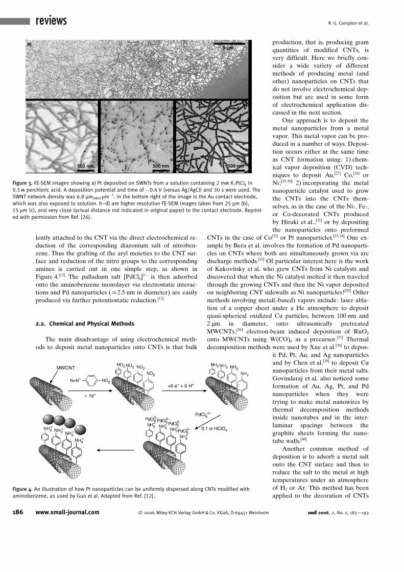
lently attached to the CNT via the direct electrochemical re-duction of the corresponding diazonium salt of nitroben-zene. Thus the grafting of the aryl moieties to the CNT sur-face and reduction of the nitro groups to the correspondingamines is carried out in one simple step, as shown inFigure 4.[12] The palladium salt [PdCl6]
2� is then adsorbedonto the aminobenzene monolayer via electrostatic interac-tions and Pd nanoparticles (�2.5 nm in diameter) are easilyproduced via further potentiostatic reduction.[12]
2.2. Chemical and Physical Methods
The main disadvantage of using electrochemical meth-ods to deposit metal nanoparticles onto CNTs is that bulk
production, that is, producing gramquantities of modified CNTs, isvery difficult. Here we briefly con-sider a wide variety of differentmethods of producing metal (andother) nanoparticles on CNTs thatdo not involve electrochemical dep-osition but are used in some formof electrochemical application dis-cussed in the next section.
One approach is to deposit themetal nanoparticles from a metalvapor. This metal vapor can be pro-duced in a number of ways. Deposi-tion occurs either at the same timeas CNT formation using: 1) chem-ical vapor deposition (CVD) tech-niques to deposit Au,[27] Co,[28] orNi;[29, 30] 2) incorporating the metalnanoparticle catalyst used to growthe CNTs into the CNTs them-selves, as in the case of the Ni-, Fe-,or Co-decorated CNTs producedby Hiraki et al. ,[31] or by depositingthe nanoparticles onto preformed
CNTs in the case of Co[32] or Pt nanoparticles.[33, 34] One ex-ample by Bera et al. involves the formation of Pd nanoparti-cles on CNTs where both are simultaneously grown via arcdischarge methods.[35] Of particular interest here is the workof Kukovitsky et al. who grew CNTs from Ni catalysts anddiscovered that when the Ni catalyst melted it then traveledthrough the growing CNTs and then the Ni vapor depositedon neighboring CNT sidewalls as Ni nanoparticles![29] Othermethods involving metal(-based) vapors include: laser abla-tion of a copper sheet under a He atmosphere to depositquasi-spherical oxidized Cu particles, between 100 nm and2 mm in diameter, onto ultrasonically pretreatedMWCNTs;[36] electron-beam induced deposition of RuO2
onto MWCNTs using W(CO)6 as a precursor.[37] Thermaldecomposition methods were used by Xue et al.[38] to depos-
it Pd, Pt, Au, and Ag nanoparticlesand by Chen et al.[39] to deposit Cunanoparticles from their metal salts.Govindaraj et al. also noticed someformation of Au, Ag, Pt, and Pdnanoparticles when they weretrying to make metal nanowires bythermal decomposition methodsinside nanotubes and in the inter-laminar spacings between thegraphite sheets forming the nano-tube walls.[40]
Another common method ofdeposition is to adsorb a metal saltonto the CNT surface and then toreduce the salt to the metal at hightemperatures under an atmosphereof H2 or Ar. This method has beenapplied to the decoration of CNTs
Figure 3. FE-SEM images showing a) Pt deposited on SWNTs from a solution containing 2 mm K2PtCl6 in0.5m perchloric acid. A deposition potential and time of �0.4 V (versus Ag/AgCl) and 30 s were used. TheSWNT network density was 6.8 mmSWNTmm�2. In the bottom right of the image is the Au contact electrode,which was also exposed to solution. b–d) are higher resolution FE-SEM images taken from 25 mm (b),15 mm (c), and very close (actual distance not indicated in original paper) to the contact electrode. Reprint-ed with permission from Ref. [26].
Figure 4. An illustration of how Pt nanoparticles can be uniformly dispersed along CNTs modified withaminobenzene, as used by Guo et al. Adapted from Ref. [12].
186 www.small-journal.com ! 2006 Wiley-VCH Verlag GmbH&Co. KGaA, D-69451 Weinheim small 2006, 2, No. 2, 182 – 193
reviews R. G. Compton et al.
with Pt,[41–45] Pt–Ru,[46] and Pd.[47] Che et al. used thismethod to deposit both Pt, Ru, and Pt-Ru nanoparticlesonto forests of CNTs.[48, 49] Fukunaga et al. demonstratedthat often, when one uses these methods, some modicum ofpatience is a prerequisite. When they sealed MWCNTs to-gether with either Ti, Nb, or Ta and a small amount of I2,into a quartz ampoule and heated it at 1000 8C for up to215 h, CNTs decorated with TiC, TaC, and NbC nanoparti-cles were formed.[50] A collaboration between the researchgroups of Lin and Wai modified the high-temperature re-duction method by carrying out the decoration of CNTswith Pt, Pd, Rh, and Ru nanoparticles via the hydrogen re-duction of the metal–b-diketone complex precursors usingsupercritical CO2 as a JgreenK solvent.[51–54]
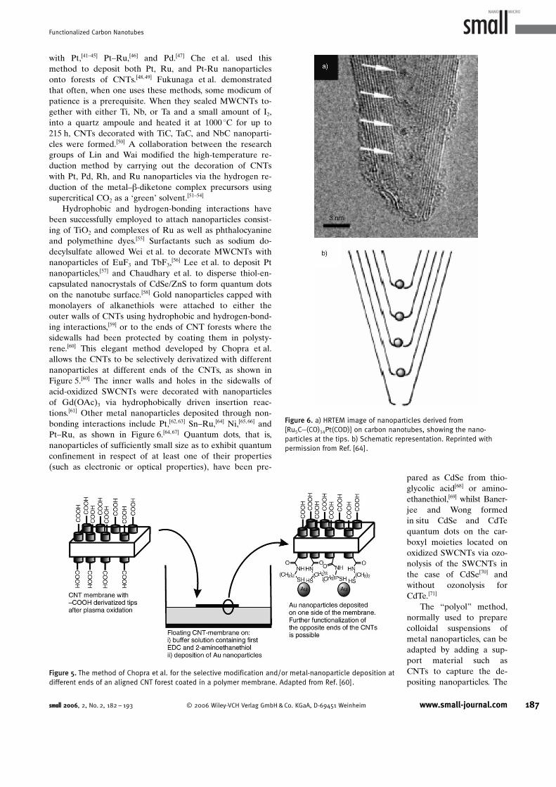
Hydrophobic and hydrogen-bonding interactions havebeen successfully employed to attach nanoparticles consist-ing of TiO2 and complexes of Ru as well as phthalocyanineand polymethine dyes.[55] Surfactants such as sodium do-decylsulfate allowed Wei et al. to decorate MWCNTs withnanoparticles of EuF3 and TbF3,
[56] Lee et al. to deposit Ptnanoparticles,[57] and Chaudhary et al. to disperse thiol-en-capsulated nanocrystals of CdSe/ZnS to form quantum dotson the nanotube surface.[58] Gold nanoparticles capped withmonolayers of alkanethiols were attached to either theouter walls of CNTs using hydrophobic and hydrogen-bond-ing interactions,[59] or to the ends of CNT forests where thesidewalls had been protected by coating them in polysty-rene.[60] This elegant method developed by Chopra et al.allows the CNTs to be selectively derivatized with differentnanoparticles at different ends of the CNTs, as shown inFigure 5.[60] The inner walls and holes in the sidewalls ofacid-oxidized SWCNTs were decorated with nanoparticlesof Gd(OAc)3 via hydrophobically driven insertion reac-tions.[61] Other metal nanoparticles deposited through non-bonding interactions include Pt,[62,63] Sn–Ru,[64] Ni,[65, 66] andPt–Ru, as shown in Figure 6.[64, 67] Quantum dots, that is,nanoparticles of sufficiently small size as to exhibit quantumconfinement in respect of at least one of their properties(such as electronic or optical properties), have been pre-
pared as CdSe from thio-glycolic acid[68] or amino-ethanethiol,[69] whilst Baner-jee and Wong formedin situ CdSe and CdTequantum dots on the car-boxyl moieties located onoxidized SWCNTs via ozo-nolysis of the SWCNTs inthe case of CdSe[70] andwithout ozonolysis forCdTe.[71]
The “polyol” method,normally used to preparecolloidal suspensions ofmetal nanoparticles, can beadapted by adding a sup-port material such asCNTs to capture the de-positing nanoparticles. The
Figure 5. The method of Chopra et al. for the selective modification and/or metal-nanoparticle deposition atdifferent ends of an aligned CNT forest coated in a polymer membrane. Adapted from Ref. [60].
Figure 6. a) HRTEM image of nanoparticles derived from[Ru5C�(CO)14Pt(COD)] on carbon nanotubes, showing the nano-particles at the tips. b) Schematic representation. Reprinted withpermission from Ref. [64].
small 2006, 2, No. 2, 182 – 193 ! 2006 Wiley-VCH Verlag GmbH&Co. KGaA, D-69451 Weinheim www.small-journal.com 187
Functionalized Carbon Nanotubes
method involves refluxing a solution of the metal salt pre-cursor at 393–443 K in a polyol solvent (normally ethyleneglycol) where the polyol homogeneously decomposes to re-lease the reducing agent for metal-ion reduction.[72] Chenet al. used this method under microwave-assisted heating todecorate CNTs with both Pt and Pt–Ru nanoparticles withdiameters of �3 nm with direct applications in fuel-celltechnology.[72, 73] A further adaptation of the polyol methodfound in the literature combines the well-known benefits ofpower of ultrasound (solvent cavitation, localized heating)to produce Pt[74, 75] and nanocrystalline Sn[76] nanoparticleson CNTs with uniform diameters less than 5 nm.
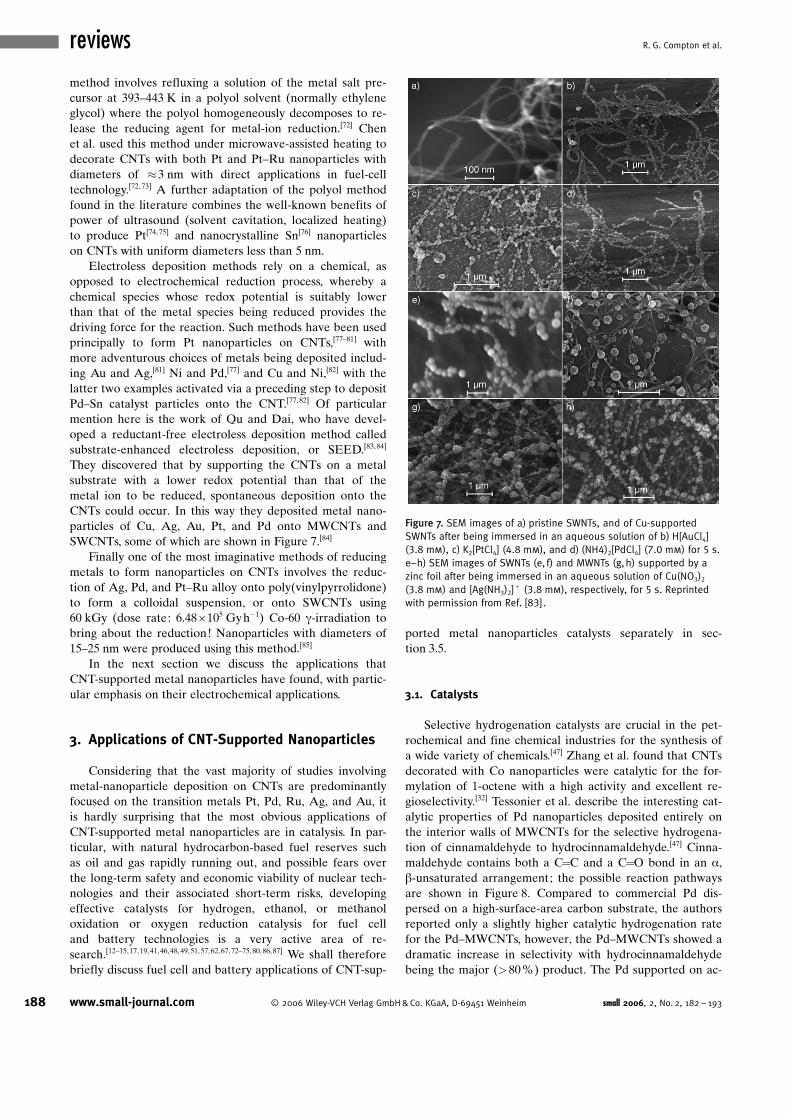
Electroless deposition methods rely on a chemical, asopposed to electrochemical reduction process, whereby achemical species whose redox potential is suitably lowerthan that of the metal species being reduced provides thedriving force for the reaction. Such methods have been usedprincipally to form Pt nanoparticles on CNTs,[77–81] withmore adventurous choices of metals being deposited includ-ing Au and Ag,[81] Ni and Pd,[77] and Cu and Ni,[82] with thelatter two examples activated via a preceding step to depositPd–Sn catalyst particles onto the CNT.[77,82] Of particularmention here is the work of Qu and Dai, who have devel-oped a reductant-free electroless deposition method calledsubstrate-enhanced electroless deposition, or SEED.[83,84]
They discovered that by supporting the CNTs on a metalsubstrate with a lower redox potential than that of themetal ion to be reduced, spontaneous deposition onto theCNTs could occur. In this way they deposited metal nano-particles of Cu, Ag, Au, Pt, and Pd onto MWCNTs andSWCNTs, some of which are shown in Figure 7.[84]
Finally one of the most imaginative methods of reducingmetals to form nanoparticles on CNTs involves the reduc-tion of Ag, Pd, and Pt–Ru alloy onto poly(vinylpyrrolidone)to form a colloidal suspension, or onto SWCNTs using60 kGy (dose rate: 6.48M105 Gyh�1) Co-60 g-irradiation tobring about the reduction! Nanoparticles with diameters of15–25 nm were produced using this method.[85]
In the next section we discuss the applications thatCNT-supported metal nanoparticles have found, with partic-ular emphasis on their electrochemical applications.
3. Applications of CNT-Supported Nanoparticles
Considering that the vast majority of studies involvingmetal-nanoparticle deposition on CNTs are predominantlyfocused on the transition metals Pt, Pd, Ru, Ag, and Au, itis hardly surprising that the most obvious applications ofCNT-supported metal nanoparticles are in catalysis. In par-ticular, with natural hydrocarbon-based fuel reserves suchas oil and gas rapidly running out, and possible fears overthe long-term safety and economic viability of nuclear tech-nologies and their associated short-term risks, developingeffective catalysts for hydrogen, ethanol, or methanoloxidation or oxygen reduction catalysis for fuel celland battery technologies is a very active area of re-search.[12–15,17,19,41,46,48,49,51,57,62,67,72–75,80,86,87] We shall thereforebriefly discuss fuel cell and battery applications of CNT-sup-
ported metal nanoparticles catalysts separately in sec-tion 3.5.
3.1. Catalysts
Selective hydrogenation catalysts are crucial in the pet-rochemical and fine chemical industries for the synthesis ofa wide variety of chemicals.[47] Zhang et al. found that CNTsdecorated with Co nanoparticles were catalytic for the for-mylation of 1-octene with a high activity and excellent re-gioselectivity.[32] Tessonier et al. describe the interesting cat-alytic properties of Pd nanoparticles deposited entirely onthe interior walls of MWCNTs for the selective hydrogena-tion of cinnamaldehyde to hydrocinnamaldehyde.[47] Cinna-maldehyde contains both a C=C and a C=O bond in an a,b-unsaturated arrangement; the possible reaction pathwaysare shown in Figure 8. Compared to commercial Pd dis-persed on a high-surface-area carbon substrate, the authorsreported only a slightly higher catalytic hydrogenation ratefor the Pd–MWCNTs, however, the Pd–MWCNTs showed adramatic increase in selectivity with hydrocinnamaldehydebeing the major (>80%) product. The Pd supported on ac-
Figure 7. SEM images of a) pristine SWNTs, and of Cu-supportedSWNTs after being immersed in an aqueous solution of b) H[AuCl4](3.8 mm), c) K2[PtCl4] (4.8 mm), and d) (NH4)2[PdCl4] (7.0 mm) for 5 s.e–h) SEM images of SWNTs (e, f) and MWNTs (g,h) supported by azinc foil after being immersed in an aqueous solution of Cu(NO3)2(3.8 mm) and [Ag(NH3)2]
+ (3.8 mm), respectively, for 5 s. Reprintedwith permission from Ref. [83].
188 www.small-journal.com ! 2006 Wiley-VCH Verlag GmbH&Co. KGaA, D-69451 Weinheim small 2006, 2, No. 2, 182 – 193
reviews R. G. Compton et al.
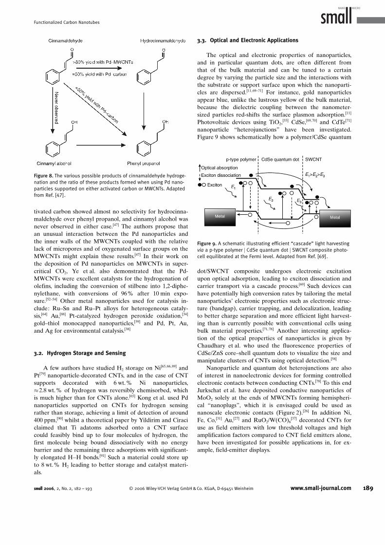
tivated carbon showed almost no selectivity for hydrocinna-maldehyde over phenyl propanol, and cinnamyl alcohol wasnever observed in either case.[47] The authors propose thatan unusual interaction between the Pd nanoparticles andthe inner walls of the MWCNTs coupled with the relativelack of micropores and of oxygenated surface groups on theMWCNTs might explain these results.[47] In their work onthe deposition of Pd nanoparticles on MWCNTs in super-critical CO2, Ye et al. also demonstrated that the Pd-MWCNTs were excellent catalysts for the hydrogenation ofolefins, including the conversion of stilbene into 1,2-diphe-nylethane, with conversions of 96% after 10 min expo-sure.[52–54] Other metal nanoparticles used for catalysis in-clude: Ru–Sn and Ru–Pt alloys for heterogeneous cataly-sis,[64] Au,[88] Pt-catalyzed hydrogen peroxide oxidation,[34]
gold–thiol monocapped nanoparticles,[59] and Pd, Pt, Au,and Ag for environmental catalysis.[38]
3.2. Hydrogen Storage and Sensing
A few authors have studied H2 storage on Ni[65,66,89] andPt[79] nanoparticle-decorated CNTs, and in the case of CNTsupports decorated with 6 wt.% Ni nanoparticles,�2.8 wt.% of hydrogen was reversibly chemisorbed, whichis much higher than for CNTs alone.[65] Kong et al. used Pdnanoparticles supported on CNTs for hydrogen sensingrather than storage, achieving a limit of detection of around400 ppm,[90] whilst a theoretical paper by Yildirim and Ciraciclaimed that Ti adatoms adsorbed onto a CNT surfacecould feasibly bind up to four molecules of hydrogen, thefirst molecule being bound dissociatively with no energybarrier and the remaining three adsorptions with significant-ly elongated H�H bonds.[91] Such a material could store upto 8 wt.% H2 leading to better storage and catalyst materi-als.
3.3. Optical and Electronic Applications
The optical and electronic properties of nanoparticles,and in particular quantum dots, are often different fromthat of the bulk material and can be tuned to a certaindegree by varying the particle size and the interactions withthe substrate or support surface upon which the nanoparti-cles are dispersed.[11,69–71] For instance, gold nanoparticlesappear blue, unlike the lustrous yellow of the bulk material,because the dielectric coupling between the nanometer-sized particles red-shifts the surface plasmon adsorption.[11]
Photovoltaic devices using TiO2,[55] CdSe,[69,70] and CdTe[71]
nanoparticle “heterojunctions” have been investigated.Figure 9 shows schematically how a polymer/CdSe quantum
dot/SWCNT composite undergoes electronic excitationupon optical adsorption, leading to exciton dissociation andcarrier transport via a cascade process.[69] Such devices canhave potentially high conversion rates by tailoring the metalnanoparticlesK electronic properties such as electronic struc-ture (bandgap), carrier trapping, and delocalization, leadingto better charge separation and more efficient light harvest-ing than is currently possible with conventional cells usingbulk material properties.[71, 78] Another interesting applica-tion of the optical properties of nanoparticles is given byChaudhary et al. who used the fluorescence properties ofCdSe/ZnS core–shell quantum dots to visualize the size andmanipulate clusters of CNTs using optical detection.[58]
Nanoparticle and quantum dot heterojunctions are alsoof interest in nanoelectronic devices for forming controlledelectronic contacts between conducting CNTs.[78] To this endJurkschat et al. have deposited conductive nanoparticles ofMoO2 solely at the ends of MWCNTs forming hemispheri-cal “nanoplugs”, which it is envisaged could be used asnanoscale electronic contacts (Figure 2).[26] In addition Ni,Fe, Co,[31] Au,[27] and RuO2/W(CO)6
[37] decorated CNTs foruse as field emitters with low threshold voltages and highamplification factors compared to CNT field emitters alone,have been investigated for possible applications in, for ex-ample, field-emitter displays.
Figure 8. The various possible products of cinnamaldehyde hydroge-nation and the ratio of these products formed when using Pd nano-particles supported on either activated carbon or MWCNTs. Adaptedfrom Ref. [47].
Figure 9. A schematic illustrating efficient “cascade” light harvestingvia a p-type polymer j CdSe quantum dot j SWCNT composite photo-cell equilibrated at the Fermi level. Adapted from Ref. [69].
small 2006, 2, No. 2, 182 – 193 ! 2006 Wiley-VCH Verlag GmbH&Co. KGaA, D-69451 Weinheim www.small-journal.com 189
Functionalized Carbon Nanotubes
3.4. Other Applications
Lu et al. have immobilized palladium nanoparticles onSWCNTs and applied this in the detection of methane. Themethodology showed advantages over conventional catalyticbeads and metal oxide sensors with a tenfold increase insensitivity and reduced power consumption by a factor of100.[92] Both Shi et al.[63] and Qiaocui et al.[44] used CNT-sup-ported Pt nanoparticles to fabricate a cholesterol biosensorinvolving the immobilization of the Pt-modified CNTs andthe cholesterase enzyme in a sol–gel matrix on an electrode.The detection of cholesterol occurred indirectly using thehydrogen peroxide produced by the action of the enzymeand allowed the sensor to have a low detection limit(1.4 mm) over a good linear range (4–100 mm). The Pt–CNTsalso limited the effect of interferents compared to bulk ma-terials or CNTs alone.[63] Also of note is the Pt–CNT-sup-ported catalysis of both hydrogen peroxide and cysteine forthe bioanalytical sensing of both species.[43] Other biologicalapplications and developments in the use of nanoparticles ingeneral, as well as CNT-supported nanoparticles, are re-viewed in great depth by Penn et al.[93] and will thereforenot be discussed further here.
In general, most applications of nanomaterials are forconstructive purposes to try to solve problems of the day,such as finding alternative power sources to hydrocarbon-based fuels using “green” fuel-cell technologies, discussed inthe next section, or solar-powered cells.
3.5. Energy Storage and Related Applications
Dong et al.[95] prepared a hybrid thin film containingplatinum nanoparticles and [tetrakis(N-methylpyridyl)por-phyrinato]cobalt (CoTMPyP) modified MWCNTs support-ed on a glassy carbon electrode (GC/MWCNT/CoTMPyP/Pt) to develop a new electrode material to exploit in fuelcells. The procedure involves physically adsorbing CoTM-PyP onto a MWCNT by simply immersing into an aqueoussolution containing CoTMPyP for 90 min. The electrode isplaced into another aqueous solution containing K2PtCl6,which allows [PtCl6]
2� to be adsorbed onto the surface ofthe modified glassy carbon electrode. Finally the electrodeis placed into an electrolyte solution to electrochemicallyreduce [PtCl6]
2� to form platinum nanoparticles in situ. Thisprocedure produces a single layer of platinum but multilay-ers can be achieved by repeating the above procedure.
The electrochemical reduction of oxygen in aqueous so-lution at this modified electrode showed excellent electroca-talysis, which was verified to be solely due to the presenceof the platinum nanoparticles. The authors established thatthe electrochemical process was occurring through a four-electron process that indicated that the final product waswater. If any of these studies are to be commercially used,such as in the fuel-cell industry, the process should ideallyproduce water as the final product since the formation ofhydrogen peroxide is an unwanted side product that canattack polymeric membranes and also significantly reducethe power efficiency.
CNTs have potential for use as membrane materialswithin fuel cells, batteries, and related technologies. Howev-er the majority of these applications will require alignmentand aggregation to form such a membrane since CNTs com-monly form bundles, which have the disadvantage of de-creasing their surface area available for supporting nanopar-ticles.[96,97]
Ajayan et al.[98] has reported a simple technique foralignment that produces aligned arrays of carbon nanotubes,which involves cutting thin slices (50–200 nm) of a nano-tube–polymer composite. However, the degree of orienta-tion of the nanotubes in the composite was affected by thethickness of the slices, and the aligning effect becomes lesspronounced with increasing slice thickness.
Fisher, Martin, and co-workers[99] have reported tem-plate-synthesized carbon tubules, which can be fabricated asfree-standing nanoporous carbon membranes. This novelconcept is realized via a CVD-based synthesis within thepores of an alumina template membrane, which produces aensemble of uniform, open-ended hollow tubes. They notedthat carbon was deposited in-between the template pores,which serves to hold the nanotube template together whenthe underlying membrane is dissolved in a HF solution, thusaffording an elegant free-standing carbon-tubule membrane.
Fisher and co-workers have filled these nanotube ensem-bles with the electrocatalytic metals of platinum and ruthe-nium and with alloys of platinum and ruthenium via immer-sion in the appropriate metal salt(s) solution, which arethen chemically reduced to the corresponding metal. Inter-estingly, capillary action results in platinum nanoclustersthat are formed exclusively on the inner walls of the CNTsensemble.
These nanoclusters of metals supported on the carbonnanotubes were then attached to a glassy carbon electrodeby using Nafion as an adhesive and were found to electro-catalyze oxidation reduction and methanol oxidation; theseare highly important reactions in fuel-cell technology. Possi-ble applications in heterogeneous catalysis are also conceiv-able.[100]
Further work from this group has shown excellent elec-trocatalysis using nanoparticle-modified nanotubes towardoxygen reduction in aqueous solution observing a large re-duction in the overpotential while noting that both theouter and inner tubules were electrochemically active forthe intercalation of lithium ions, suggesting applications inlithium-ion batteries.[101]
Girishkumar et al. have reported a membrane electrodeassembly for hydrogen fuel cells.[102] The method involveselectrophoretic deposition to form a film of functionalizedCNTs on a carbon-fiber electrode. A schematic representa-tion of the proton-exchange membrane assembly is shownin Figure 10. The benefits of this technique include uniformdeposition of charged particles with control of film mor-phology performed by modulating the applied electric field.The catalyst particles, when suspended in a solvent, becomecharged under the influence of a dc electric field and mi-grate toward the oppositely charged electrode. The film caston the electrode surface is robust, and the amount of depo-sition can be controlled by changing the duration of the ap-
190 www.small-journal.com ! 2006 Wiley-VCH Verlag GmbH&Co. KGaA, D-69451 Weinheim small 2006, 2, No. 2, 182 – 193
reviews R. G. Compton et al.
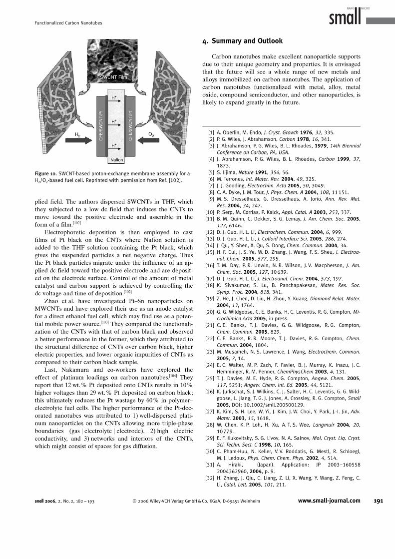
plied field. The authors dispersed SWCNTs in THF, whichthey subjected to a low dc field that induces the CNTs tomove toward the positive electrode and assemble in theform of a film.[102]
Electrophoretic deposition is then employed to castfilms of Pt black on the CNTs where Nafion solution isadded to the THF solution containing the Pt black, whichgives the suspended particles a net negative charge. Thusthe Pt black particles migrate under the influence of an ap-plied dc field toward the positive electrode and are deposit-ed on the electrode surface. Control of the amount of metalcatalyst and carbon support is achieved by controlling thedc voltage and time of deposition.[102]
Zhao et al. have investigated Pt–Sn nanoparticles onMWCNTs and have explored their use as an anode catalystfor a direct ethanol fuel cell, which may find use as a poten-tial mobile power source.[103] They compared the functionali-zation of the CNTs with that of carbon black and observeda better performance in the former, which they attributed tothe structural difference of CNTs over carbon black, higherelectric properties, and lower organic impurities of CNTs ascompared to their carbon black sample.
Last, Nakamura and co-workers have explored theeffect of platinum loadings on carbon nanotubes.[104] Theyreport that 12 wt.% Pt deposited onto CNTs results in 10%higher voltages than 29 wt.% Pt deposited on carbon black;this ultimately reduces the Pt wastage by 60% in polymer–electrolyte fuel cells. The higher performance of the Pt-dec-orated nanotubes was attributed to 1) well-dispersed plati-num nanoparticles on the CNTs allowing more triple-phaseboundaries (gas j electrolyte j electrode), 2) high electricconductivity, and 3) networks and interiors of the CNTs,which might consist of spaces for gas diffusion.
4. Summary and Outlook
Carbon nanotubes make excellent nanoparticle supportsdue to their unique geometry and properties. It is envisagedthat the future will see a whole range of new metals andalloys immobilized on carbon nanotubes. The application ofcarbon nanotubes functionalized with metal, alloy, metaloxide, compound semiconductor, and other nanoparticles, islikely to expand greatly in the future.
[1] A. Oberlin, M. Endo, J. Cryst. Growth 1976, 32, 335.[2] P. G. Wiles, J. Abrahamson, Carbon 1978, 16, 341.[3] J. Abrahamson, P. G. Wiles, B. L. Rhoades, 1979, 14th Biennial
Conference on Carbon, PA, USA.[4] J. Abrahamson, P. G. Wiles, B. L. Rhoades, Carbon 1999, 37,
1873.[5] S. Iijima, Nature 1991, 354, 56.[6] M. Terrones, Int. Mater. Rev. 2004, 49, 325.[7] J. J. Gooding, Electrochim. Acta 2005, 50, 3049.[8] C. A. Dyke, J. M. Tour, J. Phys. Chem. A 2004, 108, 11151.[9] M. S. Dresselhaus, G. Dresselhaus, A. Jorio, Ann. Rev. Mat.
Res. 2004, 34, 247.[10] P. Serp, M. Corrias, P. Kalck, Appl. Catal. A 2003, 253, 337.[11] B. M. Quinn, C. Dekker, S. G. Lemay, J. Am. Chem. Soc. 2005,
127, 6146.[12] D. J. Guo, H. L. Li, Electrochem. Commun. 2004, 6, 999.[13] D. J. Guo, H. L. Li, J. Colloid Interface Sci. 2005, 286, 274.[14] J. Qu, Y. Shen, X. Qu, S. Dong, Chem. Commun. 2004, 34.[15] H. F. Cui, J. S. Ye, W. D. Zhang, J. Wang, F. S. Sheu, J. Electroa-
nal. Chem. 2005, 577, 295.[16] T. M. Day, P. R. Unwin, N. R. Wilson, J. V. Macpherson, J. Am.
Chem. Soc. 2005, 127, 10639.[17] D. J. Guo, H. L. Li, J. Electroanal. Chem. 2004, 573, 197.[18] K. Sivakumar, S. Lu, B. Panchapakesan, Mater. Res. Soc.
Symp. Proc. 2004, 818, 341.[19] Z. He, J. Chen, D. Liu, H. Zhou, Y. Kuang, Diamond Relat. Mater.
2004, 13, 1764.[20] G. G. Wildgoose, C. E. Banks, H. C. Leventis, R. G. Compton, Mi-
crochimica Acta 2005, in press.[21] C. E. Banks, T. J. Davies, G. G. Wildgoose, R. G. Compton,
Chem. Commun. 2005, 829.[22] C. E. Banks, R. R. Moore, T. J. Davies, R. G. Compton, Chem.
Commun. 2004, 1804.[23] M. Musameh, N. S. Lawrence, J. Wang, Electrochem. Commun.
2005, 7, 14.[24] E. C. Walter, M. P. Zach, F. Favier, B. J. Murray, K. Inazu, J. C.
Hemminger, R. M. Penner, ChemPhysChem 2003, 4, 131.[25] T. J. Davies, M. E. Hyde, R. G. Compton, Angew. Chem. 2005,
117, 5251; Angew. Chem. Int. Ed. 2005, 44, 5121.[26] K. Jurkschat, S. J. Wilkins, C. J. Salter, H. C. Leventis, G. G. Wild-
goose, L. Jiang, T. G. J. Jones, A. Crossley, R. G. Compton, Small2005, DOI: 10.1002/smll.200500129.
[27] K. Kim, S. H. Lee, W. Yi, J. Kim, J. W. Choi, Y. Park, J.-I. Jin, Adv.Mater. 2003, 15, 1618.
[28] W. Chen, K. P. Loh, H. Xu, A. T. S. Wee, Langmuir 2004, 20,10779.
[29] E. F. Kukovitsky, S. G. L’vov, N. A. Sainov, Mol. Cryst. Liq. Cryst.Sci. Techn. Sect. C 1998, 10, 165.
[30] C. Pham-Huu, N. Keller, V. V. Roddatis, G. Mestl, R. Schloegl,M. J. Ledoux, Phys. Chem. Chem. Phys. 2002, 4, 514.
[31] A. Hiraki, (Japan). Application: JP 2003–1605582004362960, 2004, p. 9.
[32] H. Zhang, J. Qiu, C. Liang, Z. Li, X. Wang, Y. Wang, Z. Feng, C.Li, Catal. Lett. 2005, 101, 211.
Figure 10. SWCNT-based proton-exchange membrane assembly for aH2/O2-based fuel cell. Reprinted with permission from Ref. [102].
small 2006, 2, No. 2, 182 – 193 ! 2006 Wiley-VCH Verlag GmbH&Co. KGaA, D-69451 Weinheim www.small-journal.com 191
Functionalized Carbon Nanotubes
[33] P. Serp, R. Feurer, Y. Kihn, P. Kalck, J. L. Faria, J. L. Figueiredo, J.Phys. IV (France) 2002, 12, Pr4/29.
[34] Y.-N. Zhu, T.-Z. Peng, J.-P. Li, Gaodeng Xuexiao Huaxue Xuebao2004, 25, 1637.
[35] D. Bera, S. C. Kuiry, M. McCutchen, S. Seal, H. Heinrich, G. C.Slane, J. Appl. Phys. 2004, 96, 5152.
[36] A. Koshio, M. Shiraishi, Y. Kobayashi, M. Ishihara, Y. Koga, S.Bandow, S. Iijima, F. Kokai, Chem. Phys. Lett. 2004, 396, 410.
[37] F. Arai, P. Liu, L. Dong, T. Fukuda, T. Noguchi, K. Tatenuma,Fourth IEEE Conference on Nanotechnology, Munich, Germany,2004, 182.
[38] B. Xue, P. Chen, Q. Hong, J. Lin, K. L. Tan, J. Mater. Chem.2001, 11, 2378.
[39] P. Chen, X. Wu, J. Lin, K. L. Tan, J. Phys. Chem. B 1999, 103,4559.
[40] A. Govindaraj, B. C. Satishkumar, M. Nath, C. N. R. Rao, Chem.Mater. 2000, 12, 202.
[41] H. Huang, W. Zhang, M. Li, Y. Gan, J. Chen, Y. Kuang, J. ColloidInterface Sci. 2005, 284, 593.
[42] T. Kyotani, L.-f. Tsai, A. Tomita, Chem. Commun. 1997, 701.[43] J. Li, Q. Yu, T. Peng, Anal. Sci. 2005, 21, 377.[44] S. Qiaocui, P. Tuzhi, Z. Yunu, C. F. Yang, Electroanalysis 2005,
17, 857.[45] Y.-L. Yao, D. Zhang, X.-H. Xia, Wuji Huaxue Xuebao 2004, 20,
531.[46] M. Carmo, V. A. Paganin, J. M. Rosolen, E. R. Gonzalez, J. Power
Sources 2005, 142, 169.[47] J.-P. Tessonnier, L. Pesant, G. Ehret, M. J. Ledoux, C. Pham-Huu,
Appl. Cat. A 2005, 288, 203.[48] G. Che, B. B. Lakshmi, E. R. Fisher, C. R. Martin, Nature 1998,
393, 346.[49] G. Che, B. B. Lakshmi, C. R. Martin, E. R. Fisher, Langmuir
1999, 15, 750.[50] A. Fukunaga, S. Chu, M. E. McHenry, J. Mater. Sci. Lett. 1999,
18, 431.[51] Y. Lin, X. Cui, C. Yen, C. M. Wai, J. Phys. Chem. B 2005, 109,
14410.[52] X. R. Ye, Y. Lin, C. M. Wai, Chem. Commun. 2003, 9, 642.[53] X.-R. Ye, Y. Lin, C. Wang, M. H. Engelhard, Y. Wang, C. M. Wai, J.
Mater. Chem. 2004, 14, 908.[54] X.-R. Ye, J. B. Talbot, S. Jin, Y. Lin, C. M. Wai, Abstracts of
Papers, 229th ACS National Meeting, San Diego, CA, 2005,IEC.
[55] T. Hanyu, (Konica Minolta Medical & Graphic, Inc., Japan). Ap-plication: JP 2003–327062 2005093307, 2005, p. 22.
[56] X.-w. Wei, J. Xu, X.-j. Song, Y.-h. Ni, Zhongguo Youse JinshuXuebao 2004, 14, 236.
[57] C.-L. Lee, Y.-C. Ju, P.-T. Chou, Y.-C. Huang, L.-C. Kuo, J.-C. Oung,Electrochem. Commun. 2005, 7, 453.
[58] S. Chaudhary, J. H. Kim, K. V. Singh, M. Ozkan, Nano Lett.2004, 4, 2415.
[59] L. Han, W. Wu, F. L. Kirk, J. Luo, M. M. Maye, N. N. Kariuki, Y.Lin, C. Wang, C.-J. Zhong, Langmuir 2004, 20, 6019.
[60] N. Chopra, M. Majumder, B. J. Hinds, Adv. Funct. Mater. 2005,15, 858.
[61] A. Hashimoto, H. Yorimitsu, K. Ajima, K. Suenaga, H. Isobe, J.Miyawaki, M. Yudasaka, S. Iijima, E. Nakamura, Proc. Natl.Acad. Sci. USA 2004, 101, 8527.
[62] H.-l. Tang, M. Pan, S.-c. Mu, R.-z. Yuan, J. Wuhan Univ. Technol.2004, 19, 7.
[63] Q. Shi, T. Peng, J. Cheng, Fenxi Huaxue 2005, 33, 329.[64] S. Hermans, J. Sloan, D. S. Shephard, B. F. G. Johnson, M. L. H.
Green, Chem. Commun. 2002, 276.[65] H.-S. Kim, H. Lee, K.-S. Han, J.-H. Kim, M.-S. Song, M.-S. Park,
J.-Y. Lee, J.-K. Kang, J. Phys. Chem. B 2005, 109, 8983.[66] J.-Y. Lee, H. Lee, H.-S. Kim, Mater. Sci. Forum 2005, 475–479,
2463.
[67] Y.-H. Li, J.-F. Chen, J. Ding, Z.-Q. Mao, C.-L. Xu, D.-H. Wu, WujiCailiao Xuebao 2004, 19, 629.
[68] H.-Y. Yin, Z.-D. Xu, Y.-F. Zheng, Q.-S. Wang, W.-X. Chen, WuliHuaxue Xuebao 2004, 20, 1308.
[69] B. J. Landi, S. L. Castro, H. J. Ruf, C. M. Evans, S. G. Bailey, R. P.Raffaelle, Sol. Energ. Mater. Sol. Cells 2005, 87, 733.
[70] S. Banerjee, S. S. Wong, Chem. Commun. 2004, 1866.[71] S. Banerjee, S. S. Wong, J. Am. Chem. Soc. 2003, 125, 10342.[72] W.-X. Chen, J. Y. Lee, Z. Liu, Mater. Lett. 2004, 58, 3166.[73] W.-X. Chen, G. Han, J.-Y. Lee, Z.-L. Liu, Gaodeng Xuexiao
Huaxue Xuebao 2003, 24, 2285.[74] Y. Xing, J. Phys. Chem. B 2004, 108, 19255.[75] T. Matsumoto, T. Komatsu, H. Nakano, K. Arai, Y. Nagashima,
E. Yoo, T. Yamazaki, M. Kijima, H. Shimizu, Y. Takasawa, J. Na-kamura, Catal. Today 2004, 90, 277.
[76] L. Qiu, V. G. Pol, Y. Wei, A. Gedanken, New J. Chem. 2004, 28,1056.
[77] L.-M. Ang, T. S. A. Hor, G.-Q. Xu, C.-h. Tung, S. Zhao, J. L. S.Wang, Chem. Mater. 1999, 11, 2115.
[78] H. C. Choi, H. Dai, Abstracts of Papers, 225th ACS NationalMeeting, New Orleans, LA, United States, March 23–27, 2003,INOR.
[79] S.-c. Mu, H.-l. Tang, M. Pan, R.-z. Yuan, J. Wuhan Univ. Technol.2003, 18, 33.
[80] B. Rohland, M. Pietrzak, S. Moeller, M.-C. Bunescu, M. Wie-necke, T. Barfels, M.-C. Bunescu, Fuller. Nanotub. Car. N. 2005,13, 511.
[81] B. C. Satishkumar, E. M. Vogl, A. Govindaraj, C. N. R. Rao, J.Phys. D 1996, 29, 3173.
[82] L. M. Ang, T. S. A. Hor, G. Q. Xu, C. H. Tung, S. P. Zhao, J. L. S.Wang, Carbon 2000, 38, 363.
[83] L. Qu, L. Dai, J. Am. Chem. Soc. 2005, 127, 10806.[84] H. C. Choi, M. Shim, S. Bangsaruntip, H. Dai, J. Am. Chem. Soc.
2002, 124, 9058.[85] S.-D. Oh, B.-K. So, S.-H. Choi, A. Gopalan, K.-P. Lee, K. R. Yoon,
I. S. Choi, Mater. Lett. 2005, 59, 1121.[86] B. Rajesh, K. Venkatachalam, S. Karthikeyan, K. R. Thampi,
J. M. Bonard, B. Viswanathan, Preprints of Symposia - Ameri-can Chemical Society, Division of Fuel Chemistry, 2001, 46,452.
[87] X. Zhao, W. Li, L. Jiang, W. Zhou, Q. Xin, B. Yi, G. Sun, Carbon2004, 42, 3263.
[88] W. Lu, X. Ma, N. Lun, S. Wen, Mater. Res. Soc. Symp. Proc.2004, 820, 75.
[89] X. P. Gao, Y. Lan, G. L. Pan, F. Wu, J. Q. Qu, D. Y. Song, P. W.Shen, Electrochem. Solid-State Lett. 2001, 4, A173.
[90] J. Kong, M. G. Chapline, H. Dai, Adv. Mater. 2001, 13, 1384.[91] T. Yildirim, S. Ciraci, Phys. Rev. Lett. 2005, 94, 175501.[92] Y. Lu, J. Li, J. Han, H.-T. Ng, C. Binder, C. Partridge, M. Meyyap-
pan, Chem. Phys. Lett. 2004, 391, 344.[93] S. G. Penn, L. He, M. J. Natan, Curr. Opin. Chem. Biol. 2003, 7,
609.[94] A. L. Ramaswamy, P. Kaste, A. W. Miziolek, B. Homan, S. Trevi-
no, M. A. O’Keefe, ACS Symp. Ser. 2005, 891, 180.[95] J. Qu, Y. Shen, X. Qu, S. Dong, Chem. Commun. 2004, 1, 34.[96] Y. Zhang, T. Ichihashi, E. Landree, F. Nihey, S. Iijima, Science
1999, 285, 1719.[97] W. Z. Li, S. S. Xie, L. X. Qian, B. H. Chang, B. S. Zou, W. Y. Zhou,
R. A. Zhao, G. Wang, Science 1996, 274, 1701.[98] P. M. Ajayan, O. Stephan, C. Colliex, D. Trauth, Science 1994,
265, 1212.[99] G. Che, B. B. Lakshmi, C. R. Martin, E. R. Fisher, R. S. Ruoff,
Chem. Mater. 1998, 10, 260.[100] G. Che, B. B. Lakshmi, C. R. Martin, E. R. Fisher, Langmuir
1999, 15, 750.[101] G. Che, B. B. Lakshmi, E. R. Fisher, C. R. Martin, Nature 1998,
393, 346.
192 www.small-journal.com ! 2006 Wiley-VCH Verlag GmbH&Co. KGaA, D-69451 Weinheim small 2006, 2, No. 2, 182 – 193
reviews R. G. Compton et al.

[102] G. Girishkumar, M. Rettker, R. Underhile, D. Binz, K. Vinodgo-pal, P. McGinn, P. Kamat, Langmuir 2005, 21, 8487.
[103] X. Zhao, W. Li, L. Jiang, W. Zhou, Q. Xin, B. Yi, G. Sun, Carbon2004, 42, 3251.
[104] T. Matsumoto, T. Komatsu, K. Arai, T. Yamazaki, M. Kijima, H.Shimizu, Y. Takasawa, J. Nakamura, Chem. Commun. 2004, 7,840.
Received: September 1, 2005Revised: October 6, 2005
small 2006, 2, No. 2, 182 – 193 ! 2006 Wiley-VCH Verlag GmbH&Co. KGaA, D-69451 Weinheim www.small-journal.com 193
Functionalized Carbon Nanotubes