Embed Size (px)
Citation preview

An ejector refrigeration cyclepowered by an internal combustion engine
Reporter: Chenliang
Professor : Sumin Jin

CONTENT
Part One
Introduction
Part Two
Working principle
Part Three
Performance of an ejector
refrigeration
Part Four
References

Total energy consumed
China is now the world second largest energy producer and
consumer
Annual growth
rateThe average annual growth rate of energy
consumed is up to 5.9%
Comprehensive utilization of energy High energy consumption
per unit of outputIts value is 8.7 times, 4.9
times and 2.5 times that of the Japan , European Union
and United States.
18%
5.9% 33%
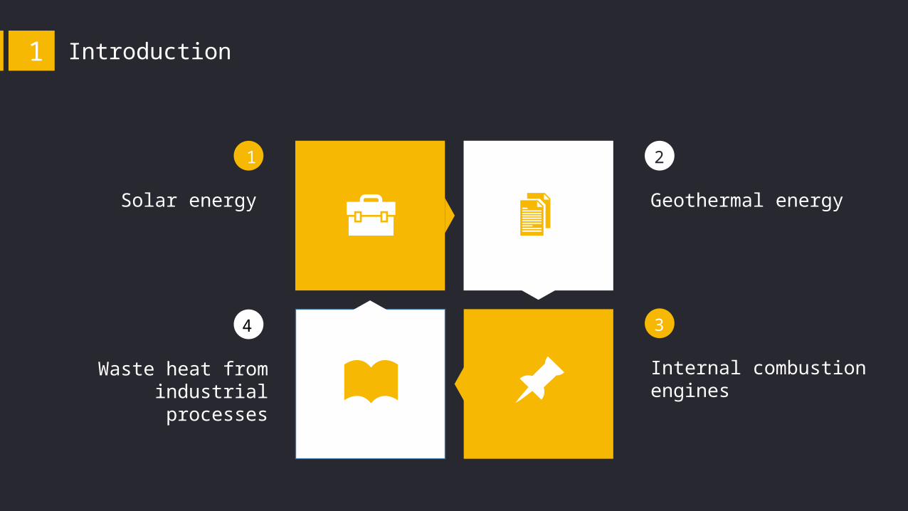
Introduction1
1
Solar energy
2
Geothermal energy
3
Internal combustion engines
4
Waste heat from industrial processes
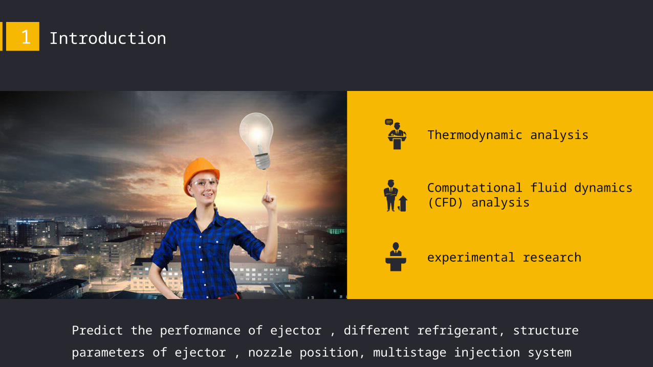
Introduction1
Introduction1
Thermodynamic analysis
Computational fluid dynamics (CFD) analysis
experimental research
Predict the performance of ejector , different refrigerant, structure parameters of
ejector , nozzle position, multistage injection system
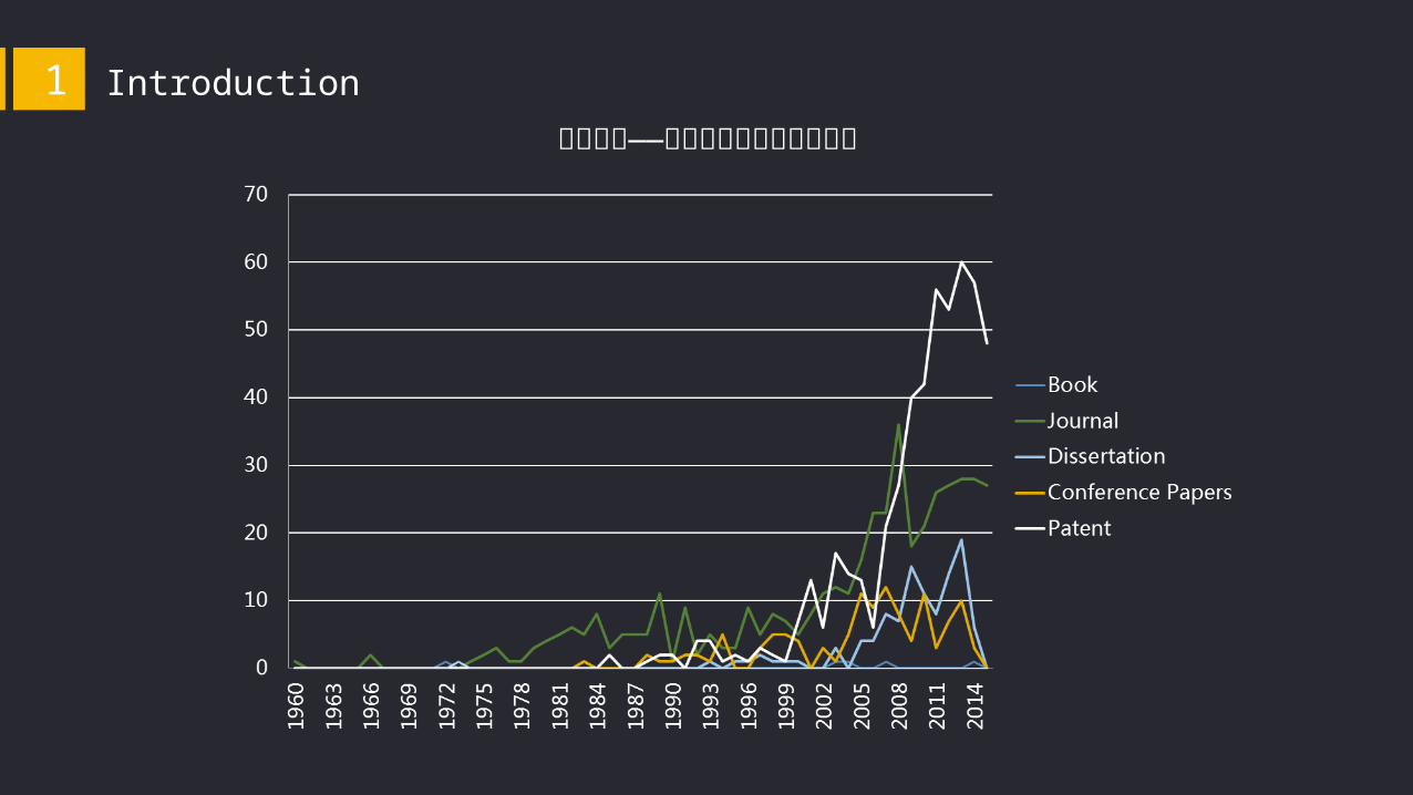
喷射制冷——各类学术发展趋势曲线图
Introduction1
CONTENT
Part One
Introduction
Part Two
Working principle
Part Three
Performance of an ejector
refrigeration
Part Four
References
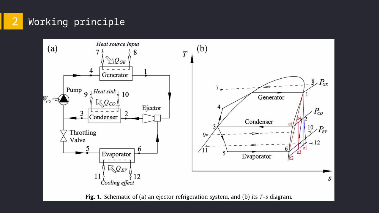
Working principle2

Working principle2

1
2
3
These systems are more reliable because there have almost no moving part.
They have more potential to be environmental friendly.
Especially, water can be used as refrigerant.
They are relatively inefficient.In an ejector refrigeration cycle, the key problem is the ejector design.
Working principle2

CONTENT
Part One
Introduction
Part Two
Working principle
Part Three
Performance of an ejector
refrigeration
Part Four
References

Performance of an ejector refrigeration 3
Refrigerant :R141b
Heat resource: exhaust gases
Inlet of generator:251.95℃, 100KPa,
0.253kg/s
Outlet of generator:98℃, 100KPa, 0.253kg/s
Cooling water:
Tcond,inlet=-5℃, Tcond,outlet=-2℃
Chilled water:
Teva,inlet=-5℃, Teva,outlet=-2℃

Performance of an ejector refrigeration 3
The refrigeration capacity and coefficient of performance increases as the
evaporator temperature increases and increase as the generator temperature
increase.
Performance of an ejector refrigeration 3
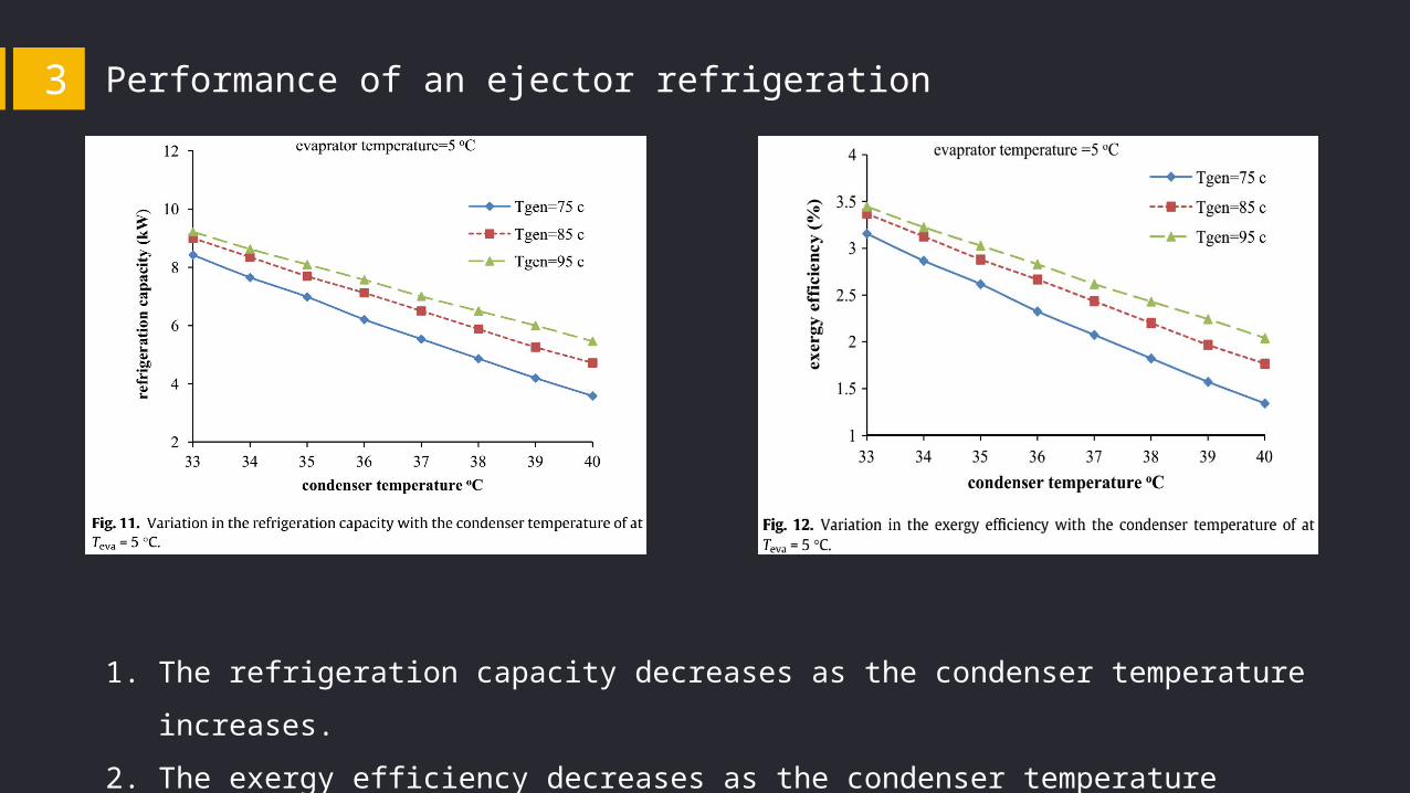
1. The refrigeration capacity decreases as the condenser temperature
increases.
2. The exergy efficiency decreases as the condenser temperature increases.
Performance of an ejector refrigeration 3
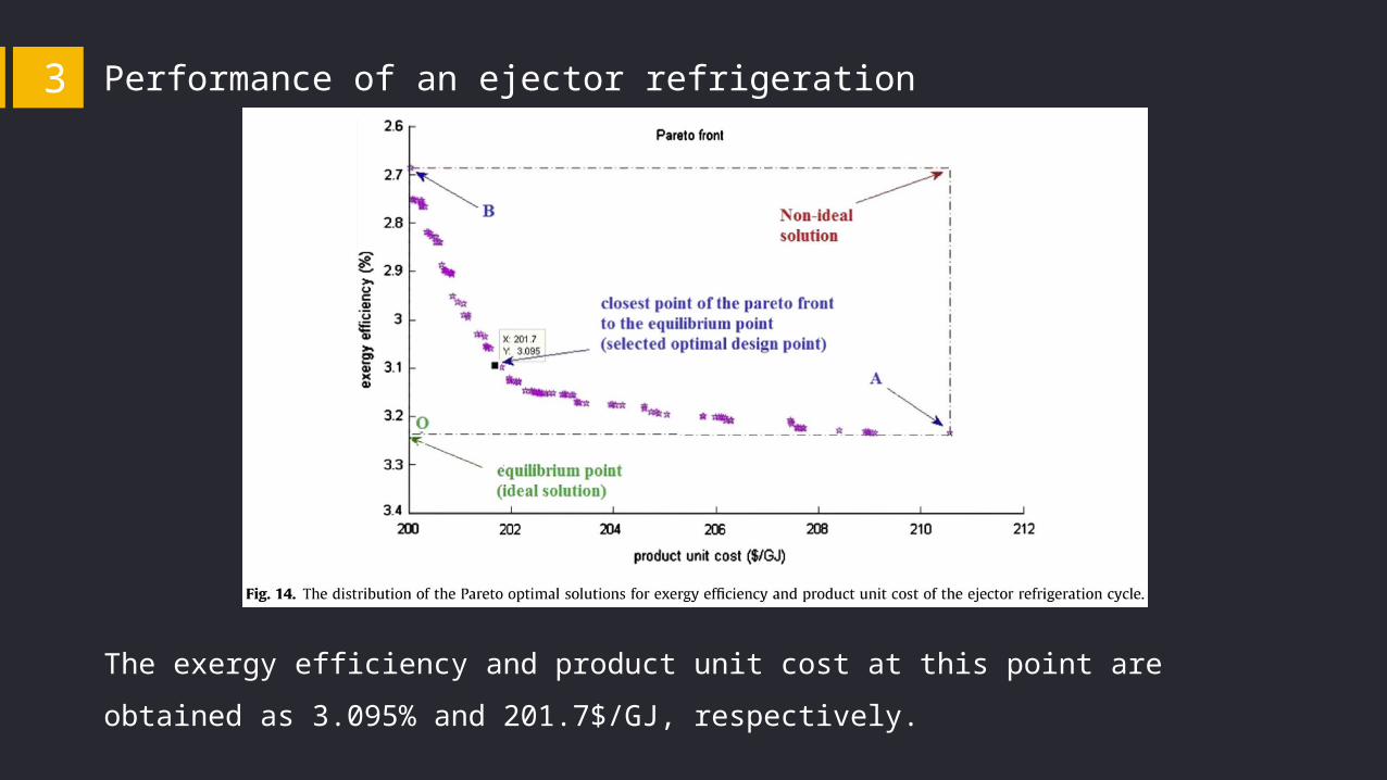
The exergy efficiency and product unit cost at this point are obtained as 3.095%
and 201.7$/GJ, respectively.
Performance of an ejector refrigeration 3
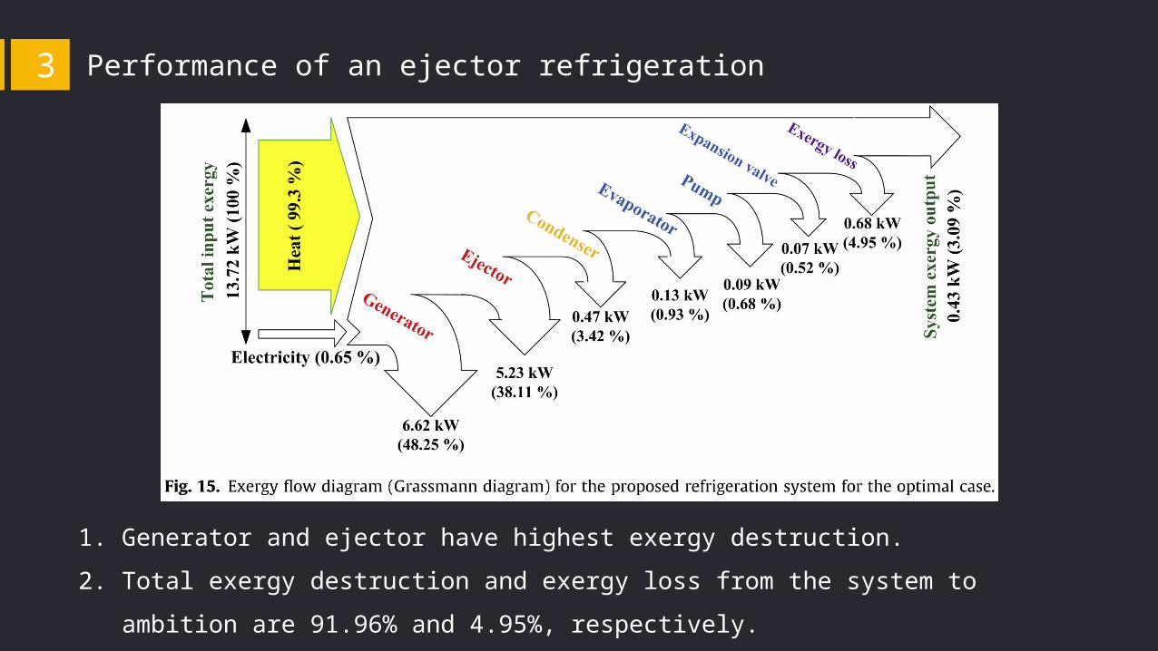
1. Generator and ejector have highest exergy destruction.
2. Total exergy destruction and exergy loss from the system to ambition are
91.96% and 4.95%, respectively.

Performance of an ejector refrigeration 3
Conclusions
1. When the ejector refrigeration system works at a generator, a condenser and
an evaporator temperatures of 94.54, 33.44 and 0.03 ℃, respectively, the
system has an optimal performance.
2. the product unit cost for the present work, obtained under optimized
condition, is 201.7 $/GJ which is comparatively more expensive than the
corresponding value for the absorption refrigeration systems.
3. The product unit cost for the present work, obtained under optimized
condition, is 201.7 $/GJ which is comparatively more expensive than the
corresponding value for the absorption refrigeration systems.

CONTENT
Part One
Introduction
Part Two
Working principle
Part Three
Performance of an ejector
refrigeration
Part Four
References

References4
1. 房煦峰 . 潜热回收型喷射式制冷性能分析及喷射器数值模拟 [D]. 大连海事大学 , 2014.
2. 董景明 . 高效喷射式制冷系统性能的理论与实验研究 [D]. 大连海事大学 ,
2012.
3. Chen J, Havtun H, Palm B. Conventional and advanced exergy
analysis of an ejector refrigeration system[J]. Applied Energy,
2015,144:139-151.
4. Sadeghi M, Mahmoudi S M S, Khoshbakhti Saray R.
Exergoeconomic analysis and multi-objective optimization of an
ejector refrigeration cycle powered by an internal combustion
(HCCI) engine[J]. Energy Conversion and Management,
2015,96:403-417.

Thank you for watching
Reporter: Chenliang
Professor : Sumin Jin