Embed Size (px)
Citation preview

Roadrunner Familiarization
Wylie, TX
Model number (3629/3630)
Rosenbauer
Safety Information
Please read all safety information!!
Safety Introduction
Familiarize yourself with all manuals supplied.
Read and follow all safety precautions
DO NOT MODIFY any equipment without authorization from the factory
Keep ignition sources away from flammable objects
Practice good housekeeping.
Safety Harnesses
For the safety of everyone on your crew. A safety harness MUST BE WORN at ALL
TIMES by any individual on the aerial!
Positioning the Truck for Operation
1. Determine if the aerial will be used as a water tower or for rescue.
2. Make sure to note ALL overhead obstructions.
3. Scan scene to position the truck for best attack.
NOTE: For the best positioning, a corner of a building is highly suggested. This gives the operator
access to two sides of the structure as well as the roof.
REMINDER: The operator should always observe the placement of the fire fighting vehicle to be sure
that there is enough space for the stabilizers to be set and the aerial to be operated without any
obstructions.
Obstructions to be most aware of include, but are not limited to: adjacent buildings, curbs, drop-offs at
road edges, man holes, vehicles, trees, over head electrical wires, ditches and culverts.
When setting up the stabilizers the ground must be firm. It is highly recommended that the operator
uses the outrigger pads provided. Setting up over manholes, underground parking facilities or storm
drains could cause serious damage to the operator and/or serious damage to the truck. The area must be
able to support 75 PSI
Setting Front of Truck to UPHILL Grades
With maximum grades the truck should be positioned with the
cab facing uphill. Aerial should be operated over the rear.
Advantages:1. Can reduce the truck’s grade by extending the rear outrigger
stabilizer jacks.
2. When truck is set up the front tires will be in contact with the
ground.
3. With the outriggers set operator has more ballast for the
operation of the aerial.
Setting Front of Truck to UPHILL Grades
Disadvantages:1. Since only the front tires are on the ground there is less resistance
to prevent truck movement.
2. The rear compartment and aerial access step are more difficult to access.
Setting Front of Truck to DOWNHILL Grades
Advantages:1. Rear compartments are closer to the ground for easier access.
2. Better resistance to keep the truck from sliding by having more tires in contact with the ground.
Disadvantages:1. Can not reduce the trucks grade by extending the front outrigger stabilizer jacks.
FRONT TIRES MUST STAY ON THE GROUND WHEN OPERATING OVER
THE FRONT OF THE TRUCK.
2. It is possible that the truck will teeter if the aerial is operated over the front
stabilizers with the front tires off the ground.
3. Their will be less ballast for aerial operations with the rear tires on the ground.
Setting Front of Truck to DOWNHILL Grades
Safety Around the VehicleEXHAUST FUMES
• Be conscious of exhaust fumes when working around the vehicle.
• Ensure that there is adequate ventilation.
• DO NOT alter emission controls.
COOLING SYSTEM
• Ensure there is adequate clearance between fan and shroud.
• DO NOT alter fan ratio, spacers or position.
• Observe fan clutch operation to ensure fan is disengaging when cooling is not necessary.
AIR INTAKE SYSTEM
• DO NOT alter any intake piping or filter locations.
Safety Around the VehicleUNDERCARRIAGE
• Notify others when working underneath the vehicle.
• Keep away from moving parts.
• Avoid hot areas such as engine, transmission, exhaust and pumps.
• Avoid ports that may eject steam or other hot fluids.
COVERS AND DOORS
• DO NOT sit, stand, climb or hang on open doors.
• Some doors are spring loaded. Use caution when opening doors.
• Use care not to get fingers and hands caught in pinch points such as hinges.
• Do not drive with doors partially closed.
TIRES AND WHEELS
• DO NOT operate vehicle with damaged or improperly inflated tires.
PRECAUTIONS FOR DRIVING SAFETY AND AERIAL OPERATION
Vehicle Safety
ENTERING, EXITING AND CLIMBING
• Keep steps, handles, rails, walking surfaces and shoes free from grease.
• Use extreme caution during inclement weather or when surfaces are wet.
• DO NOT use pump fixtures or lights as stepping surfaces.
• Make deliberate movements when entering, exiting or climbing on the
vehicle. DO NOT rush.
• DO NOT climb in areas without slip resistant surfaces and hand holds.
• Use a three point stance in which three extremities are in contact with the
vehicle, when entering, exiting or climbing on the vehicle.
Vehicle Operational Safety
VEHICLE BACKING• Use a spotter when backing vehicle.• Establish hand or verbal communication prior to backing.
• During periods of low light use spotter with wands and reflective vests.
VEHICLE CONTROL• Ensure proper tire inflation before operating vehicle.• A neutral safety switch prevents vehicle from being started in gear.• Allow starter to cool for one minute if vehicle doesn’t start within 15
seconds.• Familiarize yourself with gauges, switches and on-board accessories prior to
operating vehicle.
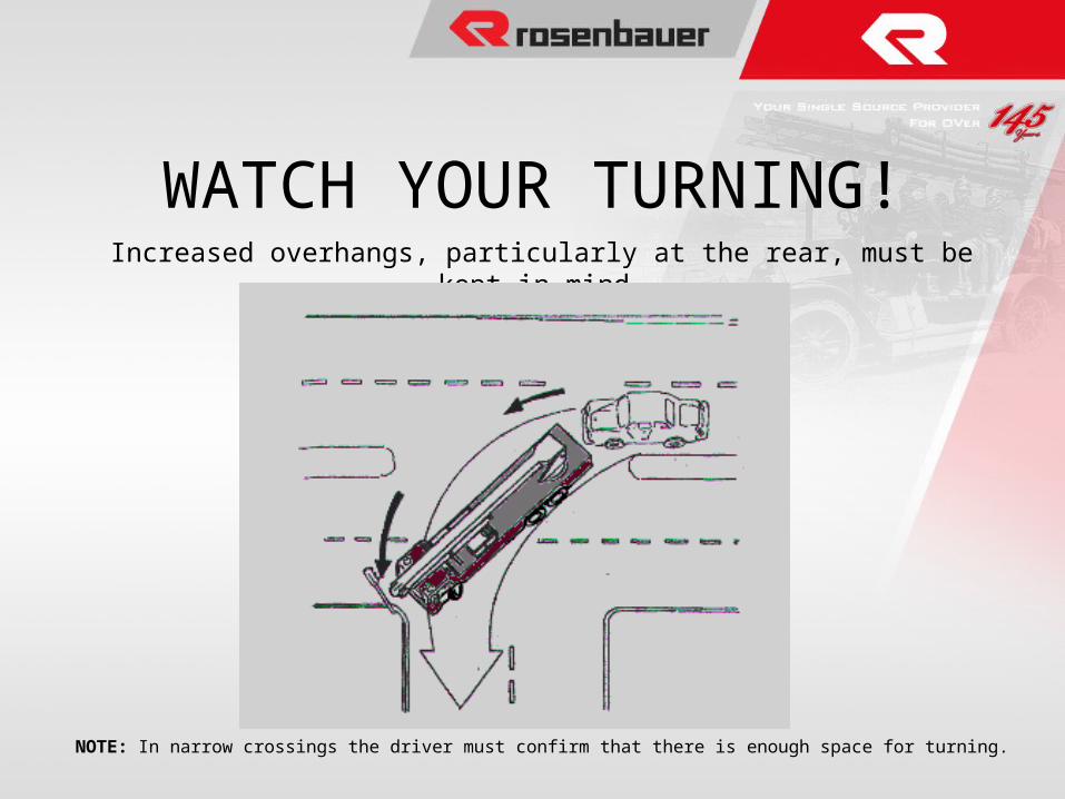
WATCH YOUR TURNING!Increased overhangs, particularly at the rear, must be kept in mind.
NOTE: In narrow crossings the driver must confirm that there is enough space for turning.
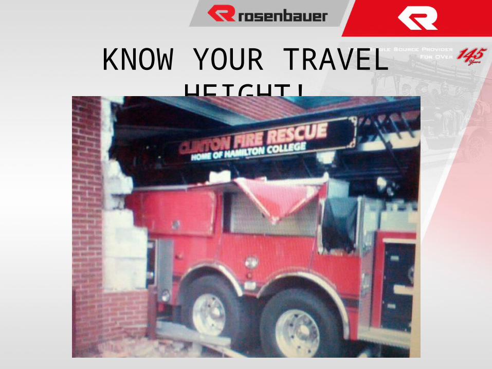
KNOW YOUR TRAVEL HEIGHT!
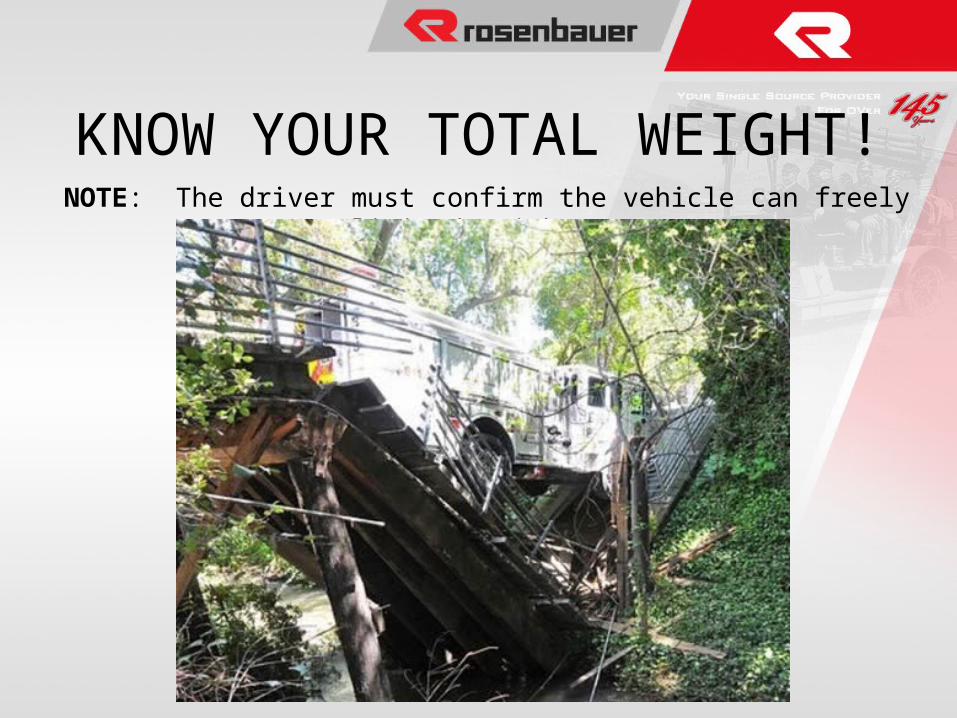
KNOW YOUR TOTAL WEIGHT!
NOTE: The driver must confirm the vehicle can freely pass limited weight areas.
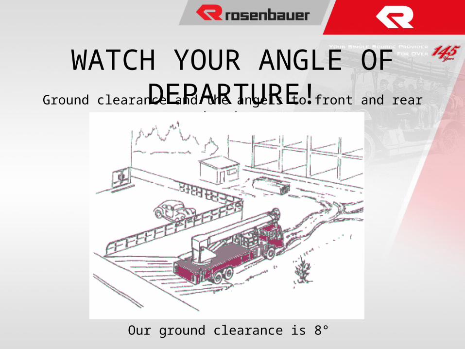
WATCH YOUR ANGLE OF DEPARTURE!Ground clearance and the angels to front and rear structures
Our ground clearance is 8°

REMEMBER HIGH CENTER OF GRAVITY!
HEIGHT OF THE CENTER OF GRAVITY.
NOTE: Speeding with the vehicle when turning a corner is DANGEROUS!
REMEMBER 60% OF YOUR WEIGHT IS ABOVE YOU
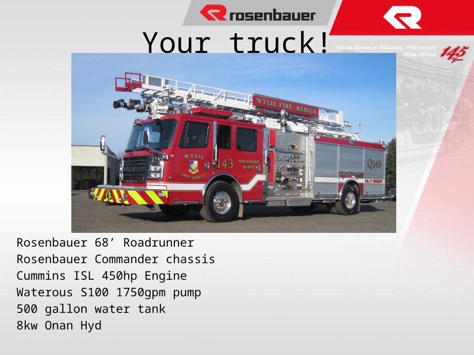
Your truck!
Rosenbauer 68’ Roadrunner
Rosenbauer Commander chassis
Cummins ISL 450hp Engine
Waterous S100 1750gpm pump
500 gallon water tank
8kw Onan Hyd
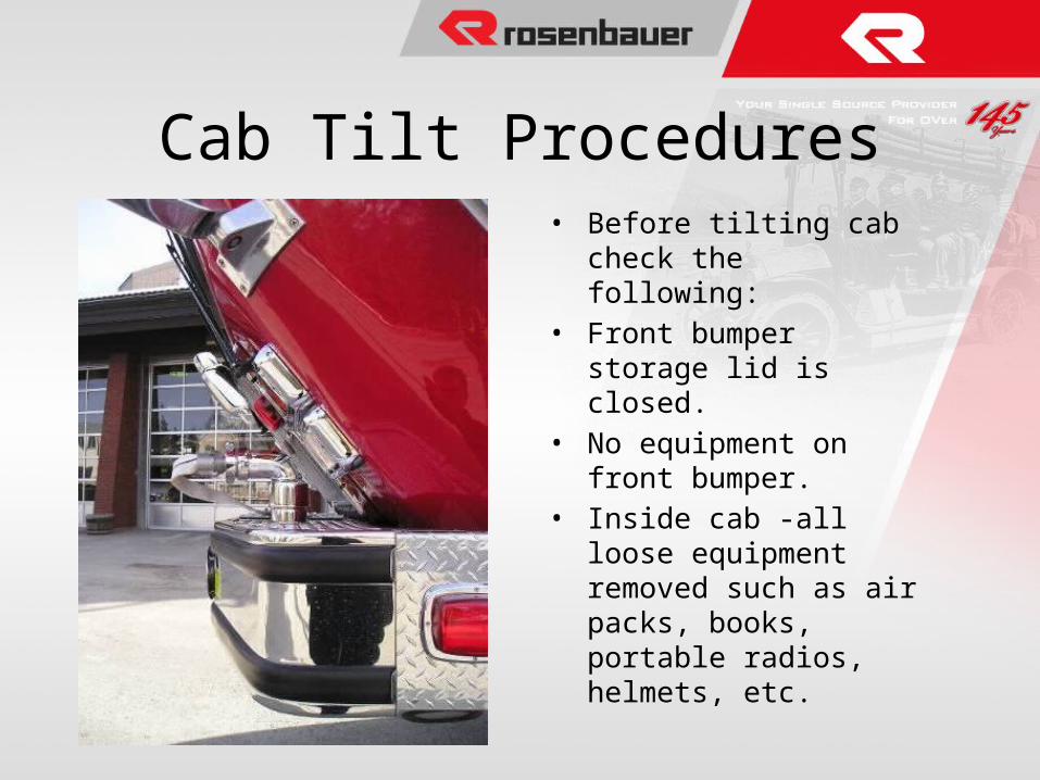
Cab Tilt Procedures• Before tilting cab check the
following:• Front bumper storage lid is
closed.• No equipment on front
bumper.• Inside cab -all loose
equipment removed such as air packs, books, portable radios, helmets, etc.
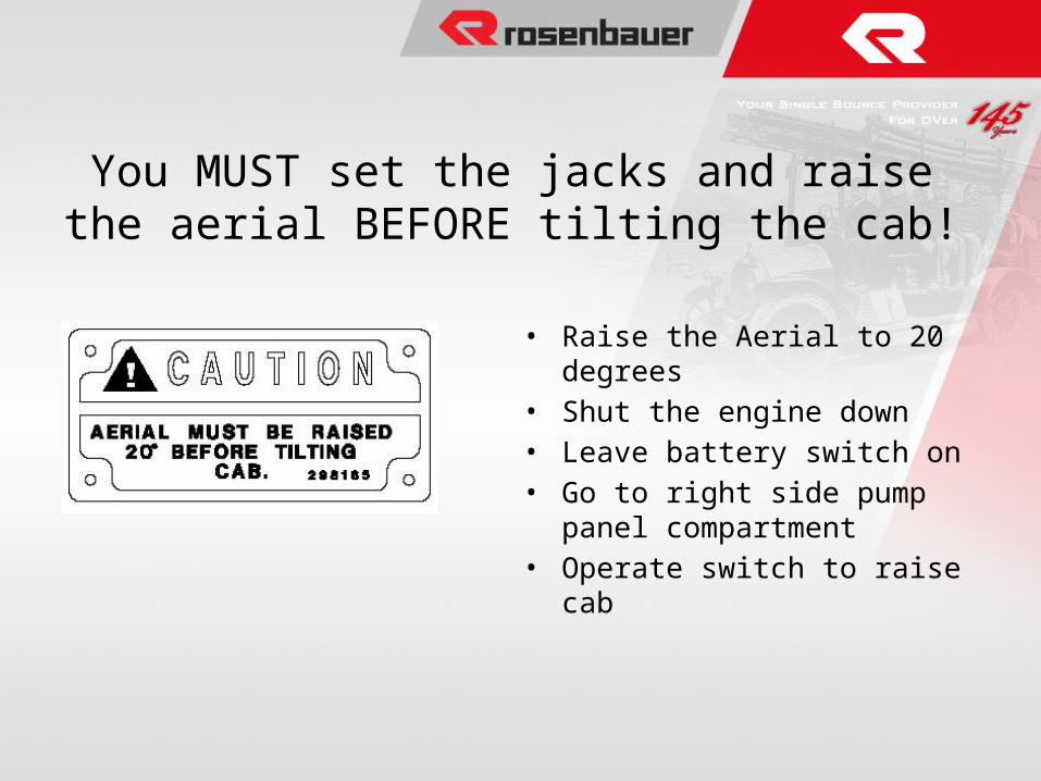
You MUST set the jacks and raise the aerial BEFORE tilting the cab!
• Raise the Aerial to 20 degrees• Shut the engine down• Leave battery switch on• Go to right side pump panel
compartment• Operate switch to raise cab
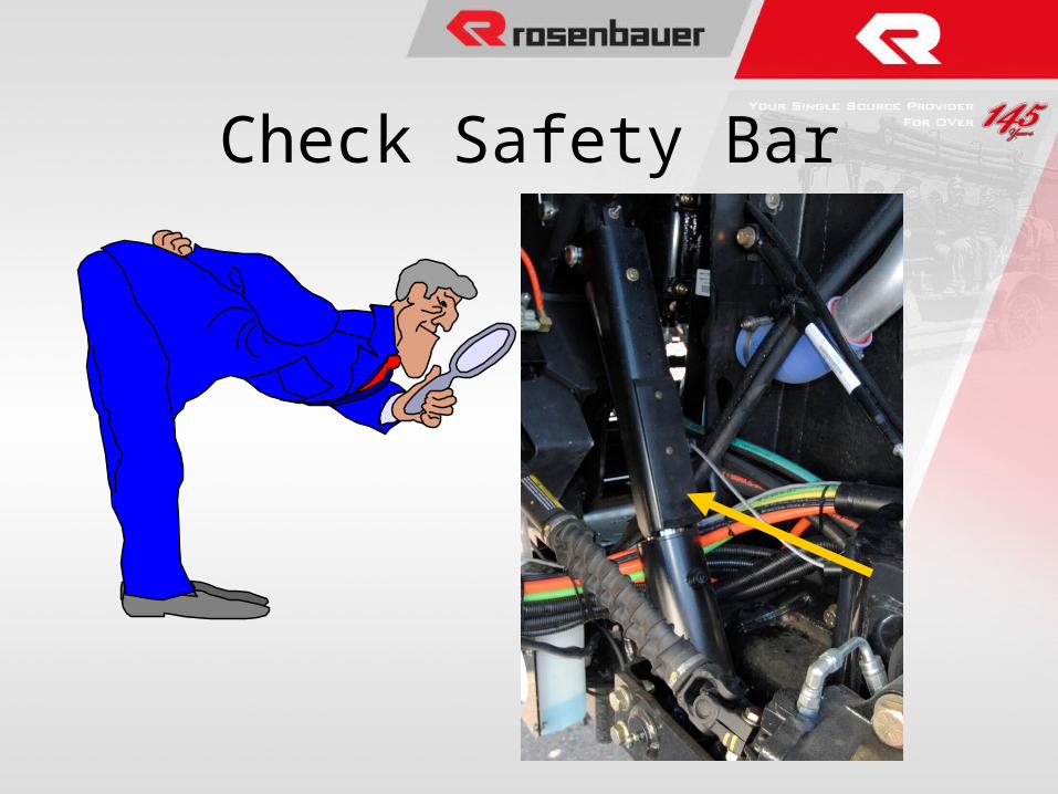
Check Safety Bar
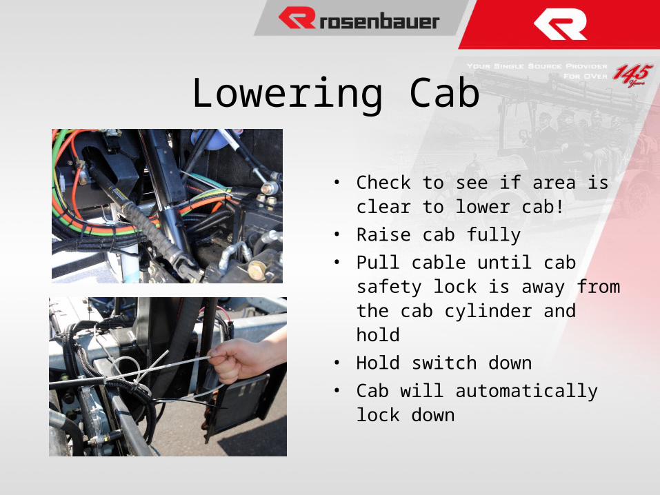
Lowering Cab
• Check to see if area is clear to lower cab!
• Raise cab fully
• Pull cable until cab safety lock is away from the cab cylinder and hold
• Hold switch down
• Cab will automatically lock down
Pump & Plumbing InfoWaterous S100 1750 GPM pump
Stainless Steel plumbing
Discharges
Crosslays
2-1/2” Discharges
LDH Discharges
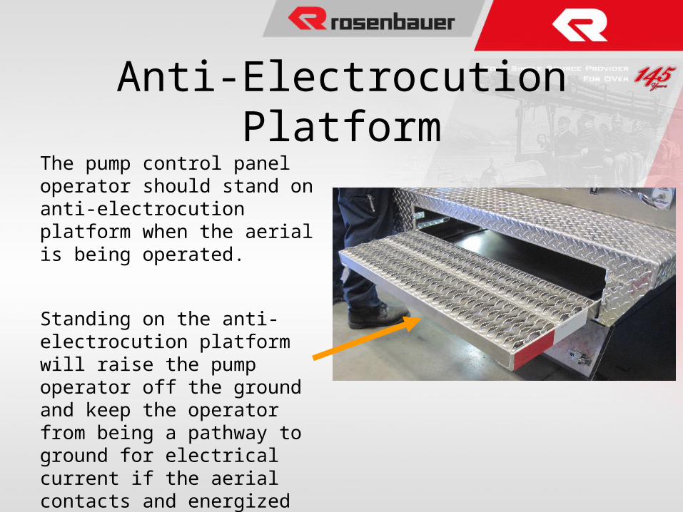
Anti-Electrocution PlatformThe pump control panel operator should stand on anti-electrocution platform when the aerial is being operated.
Standing on the anti-electrocution platform will raise the pump operator off the ground and keep the operator from being a pathway to ground for electrical current if the aerial contacts and energized line.
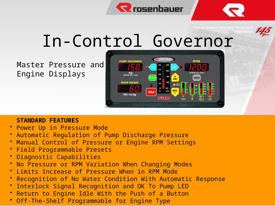
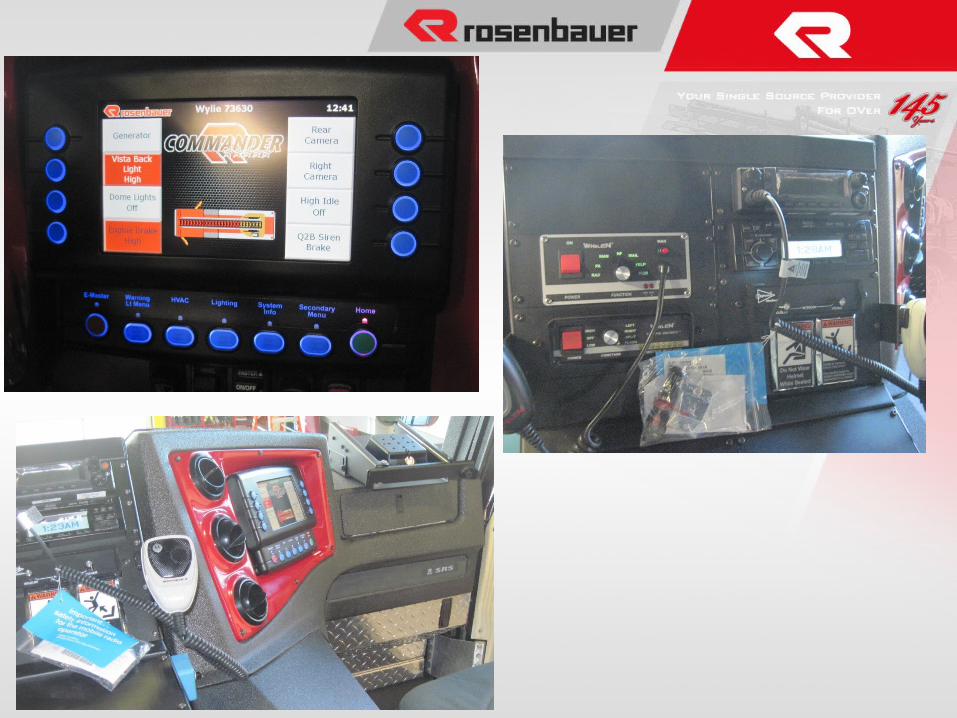
In-Control GovernorMaster Pressure and Engine Displays
STANDARD FEATURES• Power Up in Pressure Mode • Automatic Regulation of Pump Discharge Pressure • Manual Control of Pressure or Engine RPM Settings • Field Programmable Presets • Diagnostic Capabilities • No Pressure or RPM Variation When Changing Modes • Limits Increase of Pressure When in RPM Mode • Recognition of No Water Condition With Automatic Response • Interlock Signal Recognition and OK To Pump LED • Return to Engine Idle With the Push of a Button • Off-The-Shelf Programmable for Engine Type
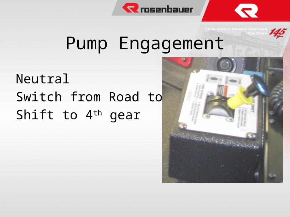
Pump Engagement
Neutral
Switch from Road to Pump
Shift to 4th gear
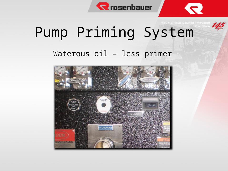
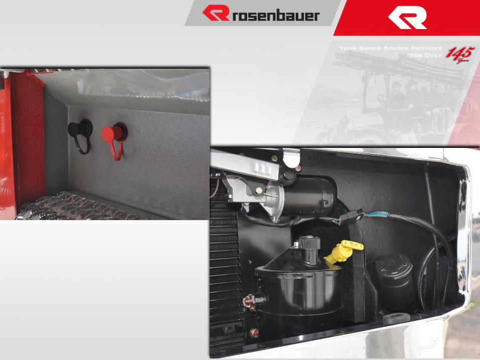
Pump Priming SystemWaterous oil – less primer
33
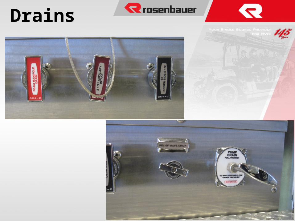
Drains
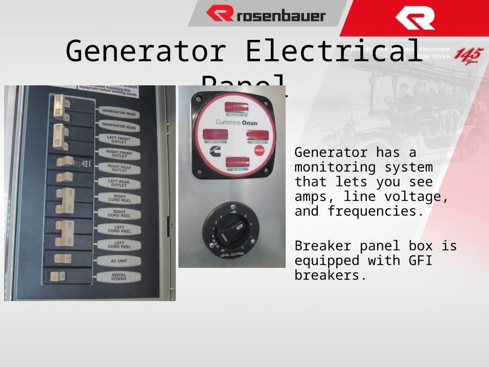
Generator Electrical Panel
Generator has a monitoring system that lets you see amps, line voltage, and frequencies.
Breaker panel box is equipped with GFI breakers.
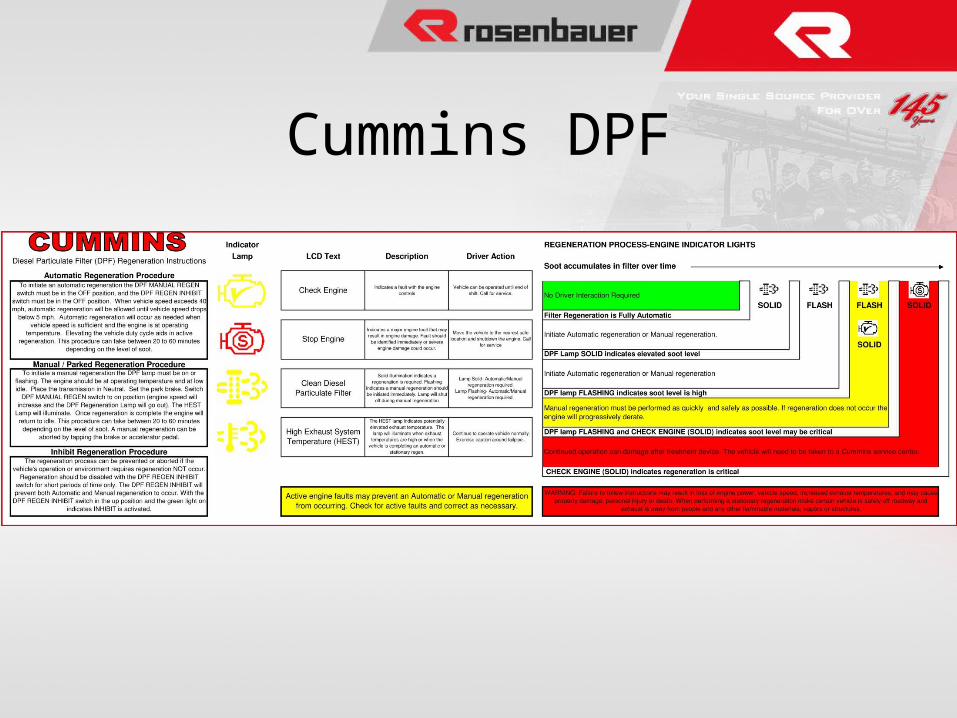
Cummins DPF
Aerial Technical Information
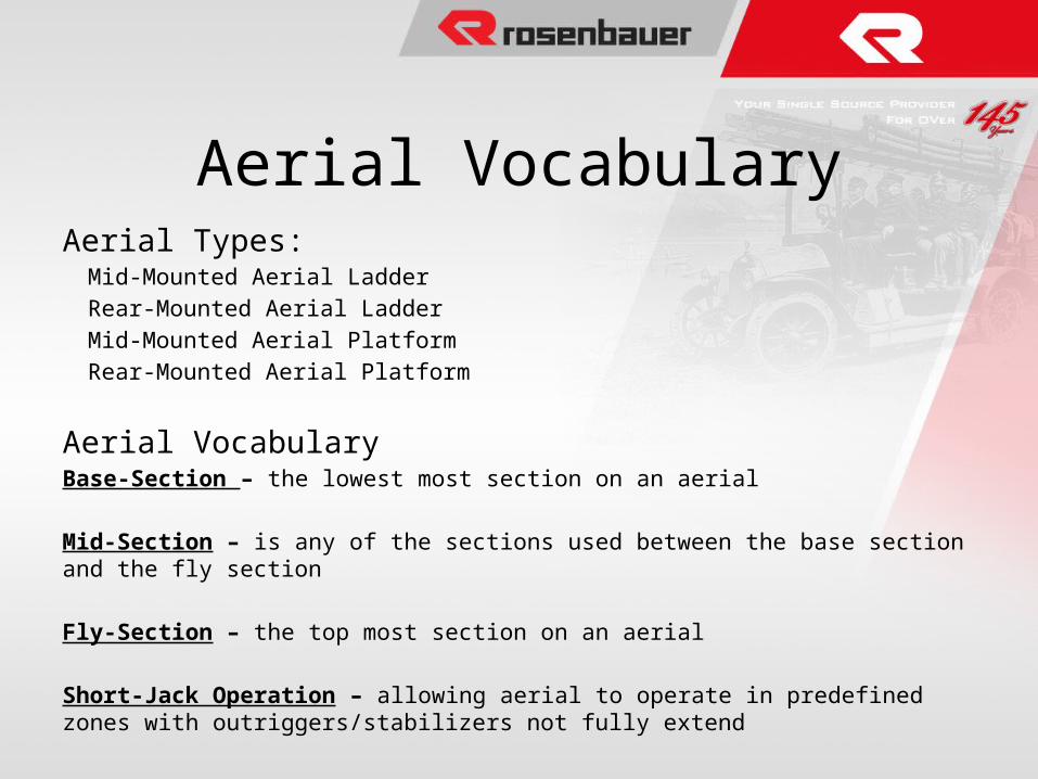
Aerial VocabularyAerial Types:
Mid-Mounted Aerial Ladder
Rear-Mounted Aerial Ladder
Mid-Mounted Aerial Platform
Rear-Mounted Aerial Platform
Aerial VocabularyBase-Section – the lowest most section on an aerial
Mid-Section – is any of the sections used between the base section and the fly section
Fly-Section – the top most section on an aerial
Short-Jack Operation – allowing aerial to operate in predefined zones with outriggers/stabilizers not fully extend
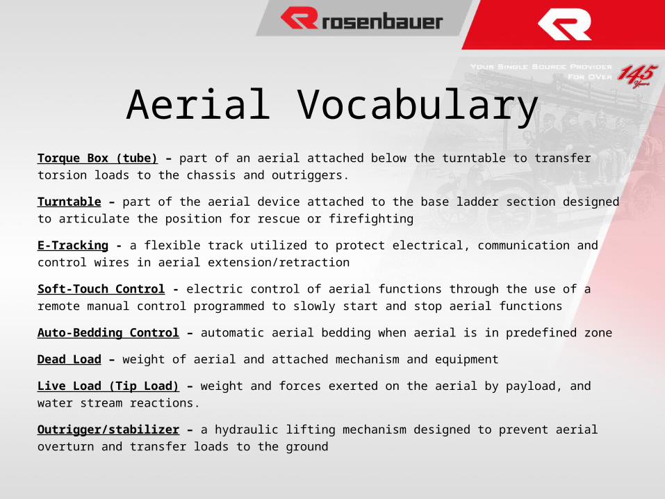
Torque Box (tube) – part of an aerial attached below the turntable to transfer torsion loads to the chassis and
outriggers.
Turntable – part of the aerial device attached to the base ladder section designed to articulate the position for
rescue or firefighting
E-Tracking - a flexible track utilized to protect electrical, communication and control wires in aerial
extension/retraction
Soft-Touch Control - electric control of aerial functions through the use of a remote manual control
programmed to slowly start and stop aerial functions
Auto-Bedding Control – automatic aerial bedding when aerial is in predefined zone
Dead Load – weight of aerial and attached mechanism and equipment
Live Load (Tip Load) – weight and forces exerted on the aerial by payload, and water stream reactions.
Outrigger/stabilizer – a hydraulic lifting mechanism designed to prevent aerial overturn and transfer loads to
the ground
Aerial Vocabulary
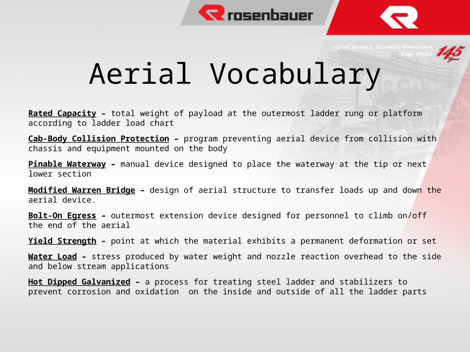
Rated Capacity – total weight of payload at the outermost ladder rung or platform according to ladder load chart
Cab-Body Collision Protection – program preventing aerial device from collision with chassis and equipment mounted on the body
Pinable Waterway – manual device designed to place the waterway at the tip or next lower section
Modified Warren Bridge – design of aerial structure to transfer loads up and down the aerial device.
Bolt-On Egress – outermost extension device designed for personnel to climb on/off the end of the aerial
Yield Strength – point at which the material exhibits a permanent deformation or set
Water Load – stress produced by water weight and nozzle reaction overhead to the side and below stream applications
Hot Dipped Galvanized – a process for treating steel ladder and stabilizers to prevent corrosion and oxidation on the inside and outside of all the ladder parts
Aerial Vocabulary
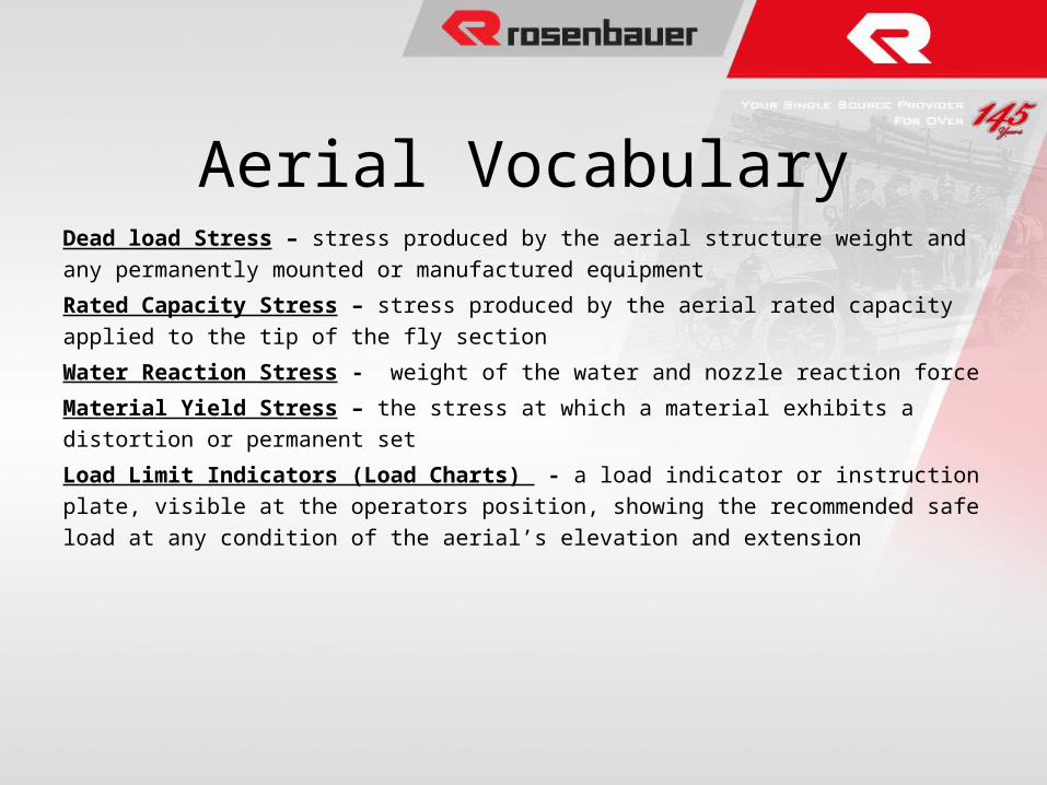
Dead load Stress – stress produced by the aerial structure weight and any permanently mounted or
manufactured equipment
Rated Capacity Stress – stress produced by the aerial rated capacity applied to the tip of the fly section
Water Reaction Stress - weight of the water and nozzle reaction force
Material Yield Stress – the stress at which a material exhibits a distortion or permanent set
Load Limit Indicators (Load Charts) - a load indicator or instruction plate, visible at the operators
position, showing the recommended safe load at any condition of the aerial’s elevation and extension
Aerial Vocabulary
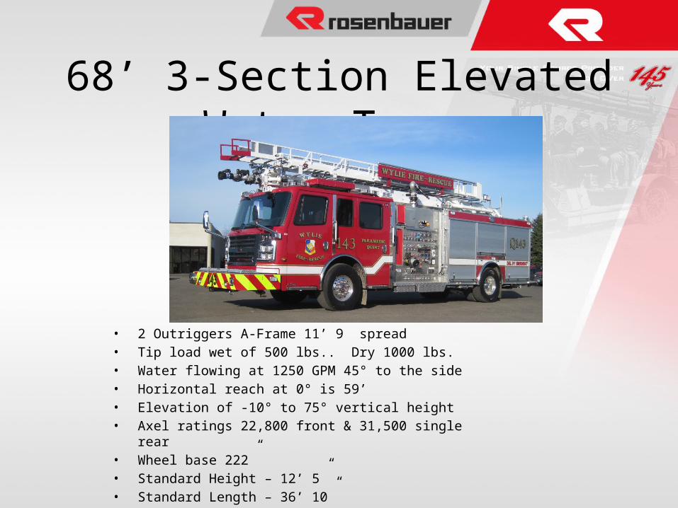
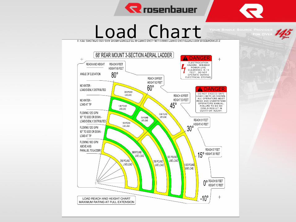
68’ 3-Section Elevated Water Tower
• 2 Outriggers A-Frame 11’ 9” spread• Tip load wet of 500 lbs.. Dry 1000 lbs.• Water flowing at 1250 GPM 45° to the side• Horizontal reach at 0° is 59’• Elevation of -10° to 75° vertical height• Axel ratings 22,800 front & 31,500 single rear• Wheel base 222”• Standard Height – 12’ 5”• Standard Length – 36’ 10”
Load Chart
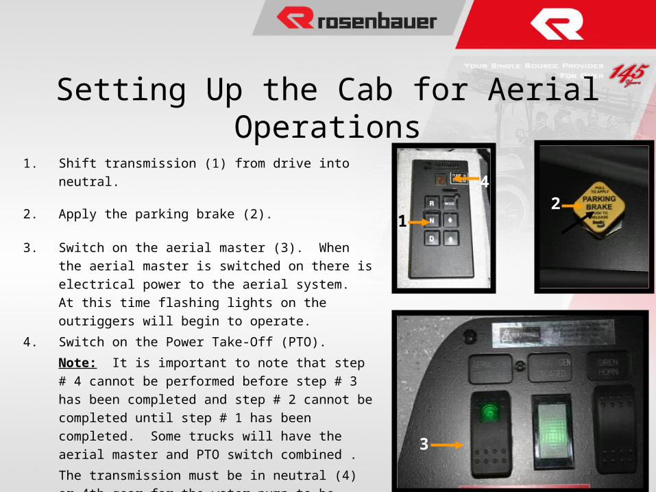
Setting Up the Cab for Aerial Operations
1. Shift transmission (1) from drive into neutral.
2. Apply the parking brake (2).
3. Switch on the aerial master (3). When the aerial master is
switched on there is electrical power to the aerial system. At
this time flashing lights on the outriggers will begin to
operate.
4. Switch on the Power Take-Off (PTO).
Note: It is important to note that step # 4 cannot be
performed before step # 3 has been completed and step # 2
cannot be completed until step # 1 has been completed. Some
trucks will have the aerial master and PTO switch combined .
The transmission must be in neutral (4) or 4th gear for the
water pump to be engaged. The parking brake must be set
before the ladder power will operate. If the water pump is
engaged, the high idle of the aerial will be disengaged.
12
4
3
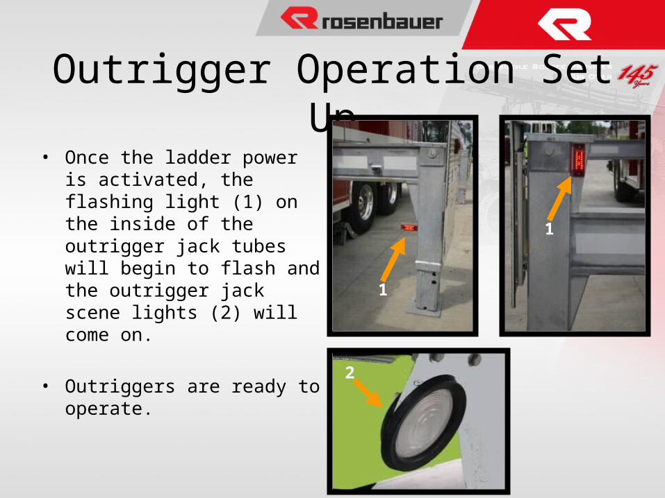
Outrigger Operation Set Up• Once the ladder power is
activated, the flashing light (1) on the inside of the outrigger jack tubes will begin to flash and the outrigger jack scene lights (2) will come on.
• Outriggers are ready to operate.
1
1
2
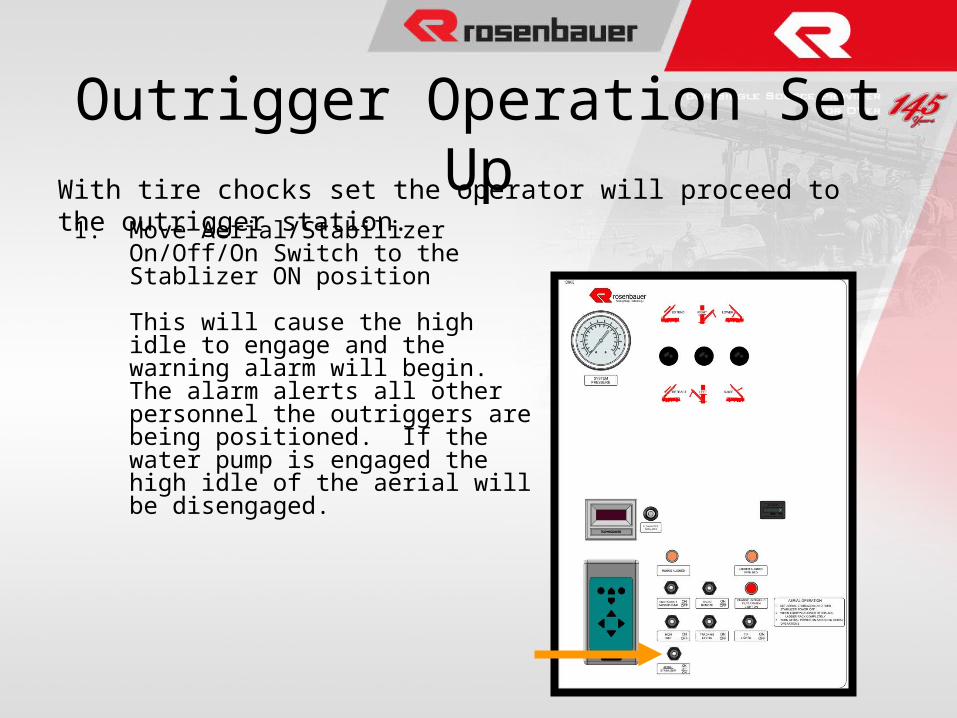
Outrigger Operation Set UpWith tire chocks set the operator will proceed to the outrigger station.
1. Move Aerial/Stabilizer On/Off/On Switch to the Stablizer ON position
This will cause the high idle to engage and the warning alarm will begin. The alarm alerts all other personnel the outriggers are being positioned. If the water pump is engaged the high idle of the aerial will be disengaged.
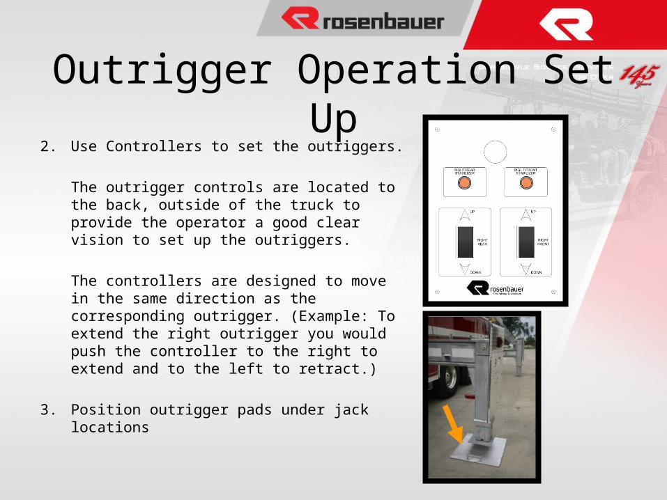
2. Use Controllers to set the outriggers.
The outrigger controls are located to the back, outside of the truck to provide the operator a good clear vision to set up the outriggers.
The controllers are designed to move in the same direction as the corresponding outrigger. (Example: To extend the right outrigger you would push the controller to the right to extend and to the left to retract.)
3. Position outrigger pads under jack locations
Outrigger Operation Set Up
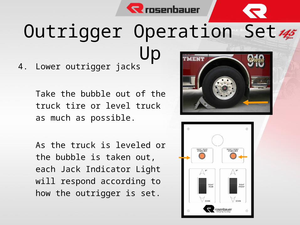
4. Lower outrigger jacks
Take the bubble out of the truck tire or
level truck as much as possible.
As the truck is leveled or the bubble is
taken out, each Jack Indicator Light will
respond according to how the outrigger
is set.
Outrigger Operation Set Up
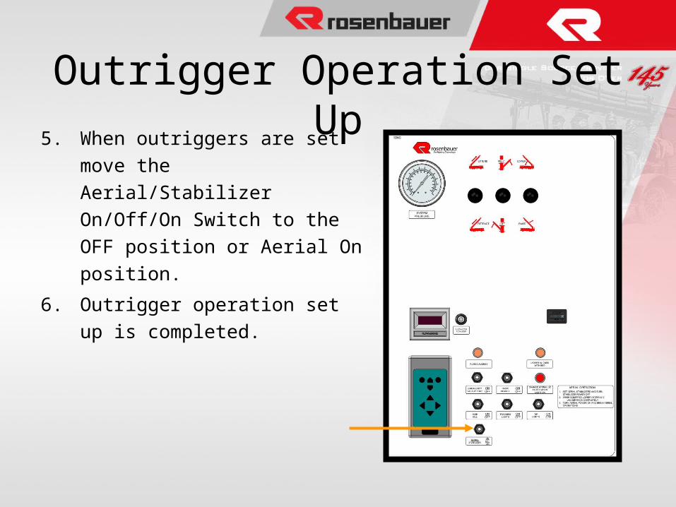
5. When outriggers are set move the
Aerial/Stabilizer On/Off/On Switch
to the OFF position or Aerial On
position.
6. Outrigger operation set up is
completed.
Outrigger Operation Set Up
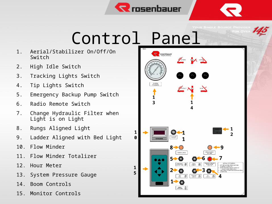
Control Panel1. Aerial/Stabilizer On/Off/On Switch
2. High Idle Switch
3. Tracking Lights Switch
4. Tip Lights Switch
5. Emergency Backup Pump Switch
6. Radio Remote Switch
7. Change Hydraulic Filter when Light is on Light
8. Rungs Aligned Light
9. Ladder Aligned with Bed Light
10. Flow Minder
11. Flow Minder Totalizer
12. Hour Meter
13. System Pressure Gauge
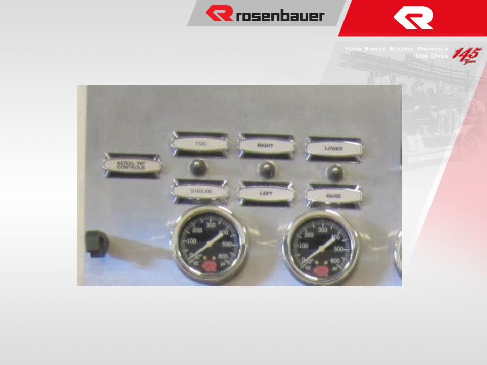
14. Boom Controls
15. Monitor Controls
1
2
5
8
34
6 7
9
15
10
121
1
13 1
4
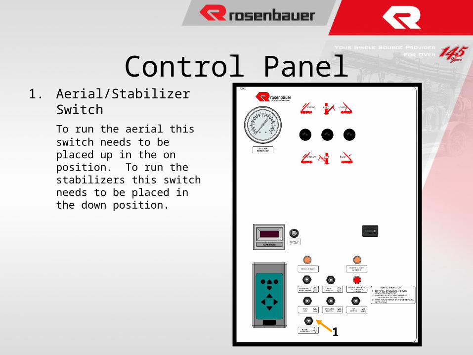
1. Aerial/Stabilizer Switch
To run the aerial this switch needs to be placed up in the on position. To run the stabilizers this switch needs to be placed in the down position.
Control Panel
1
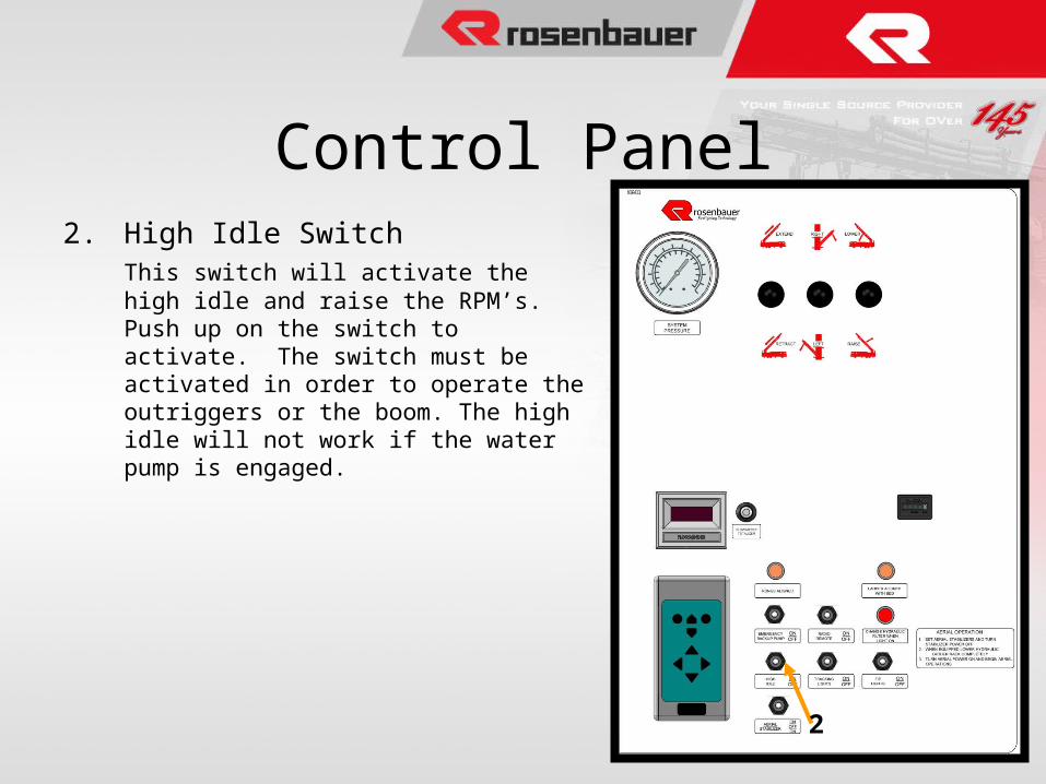
2. High Idle SwitchThis switch will activate the high idle and raise the RPM’s. Push up on the switch to activate. The switch must be activated in order to operate the outriggers or the boom. The high idle will not work if the water pump is engaged.
Control Panel
2
3. Tracking Lights Switch
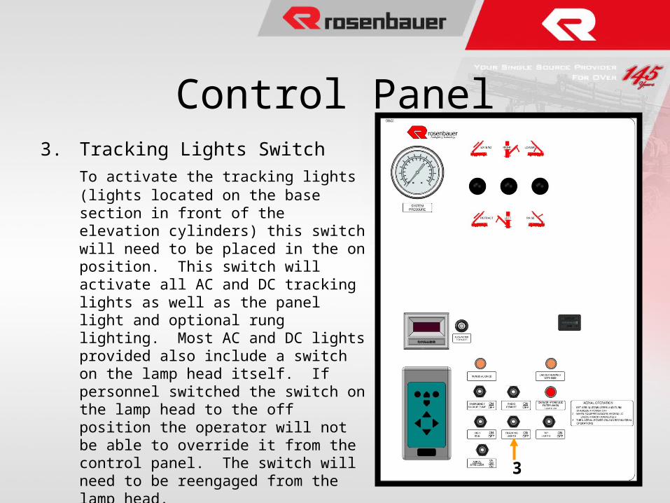
To activate the tracking lights (lights located on the base section in front of the elevation cylinders) this switch will need to be placed in the on position. This switch will activate all AC and DC tracking lights as well as the panel light and optional rung lighting. Most AC and DC lights provided also include a switch on the lamp head itself. If personnel switched the switch on the lamp head to the off position the operator will not be able to override it from the control panel. The switch will need to be reengaged from the lamp head.
Control Panel
3
Control Panel
4
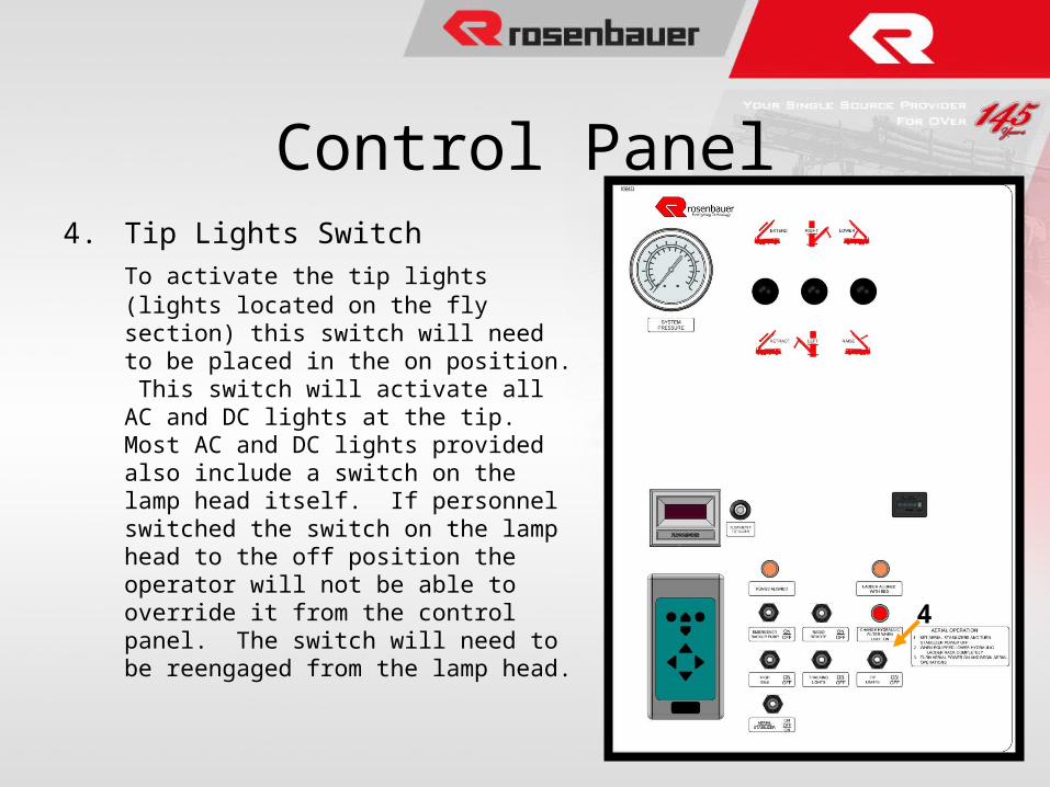
4. Tip Lights Switch
To activate the tip lights (lights located on the fly section) this switch will need to be placed in the on position. This switch will activate all AC and DC lights at the tip. Most AC and DC lights provided also include a switch on the lamp head itself. If personnel switched the switch on the lamp head to the off position the operator will not be able to override it from the control panel. The switch will need to be reengaged from the lamp head.
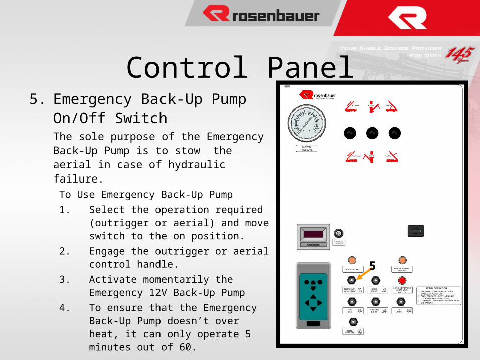
5. Emergency Back-Up Pump On/Off SwitchThe sole purpose of the Emergency Back-Up Pump is to stow the aerial in case of hydraulic failure.
To Use Emergency Back-Up Pump
1. Select the operation required (outrigger or aerial) and move switch to the on position.
2. Engage the outrigger or aerial control handle.
3. Activate momentarily the Emergency 12V Back-Up Pump
4. To ensure that the Emergency Back-Up Pump doesn’t over heat, it can only operate 5 minutes out of 60.
Control Panel
5
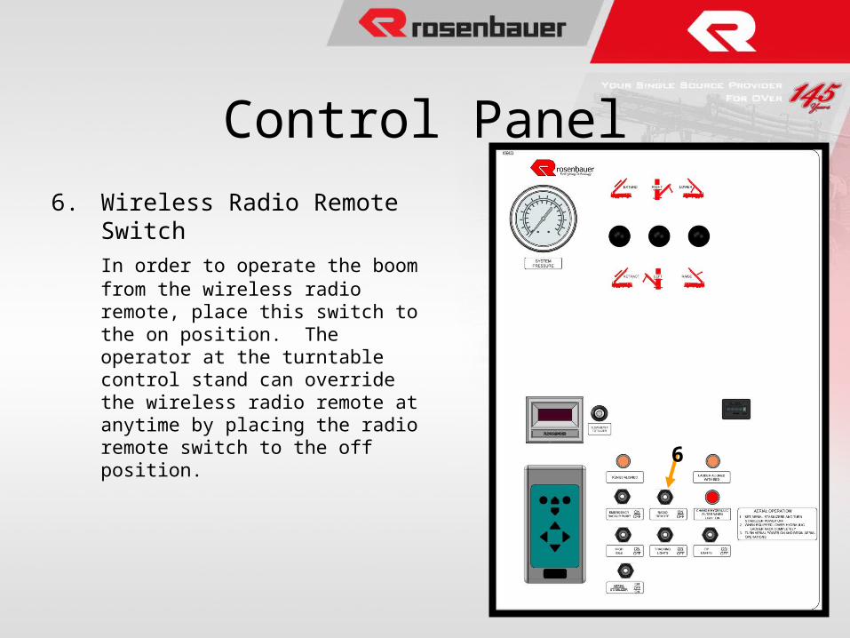
6. Wireless Radio Remote Switch
In order to operate the boom from the wireless radio remote, place this switch to the on position. The operator at the turntable control stand can override the wireless radio remote at anytime by placing the radio remote switch to the off position.
Control Panel
6
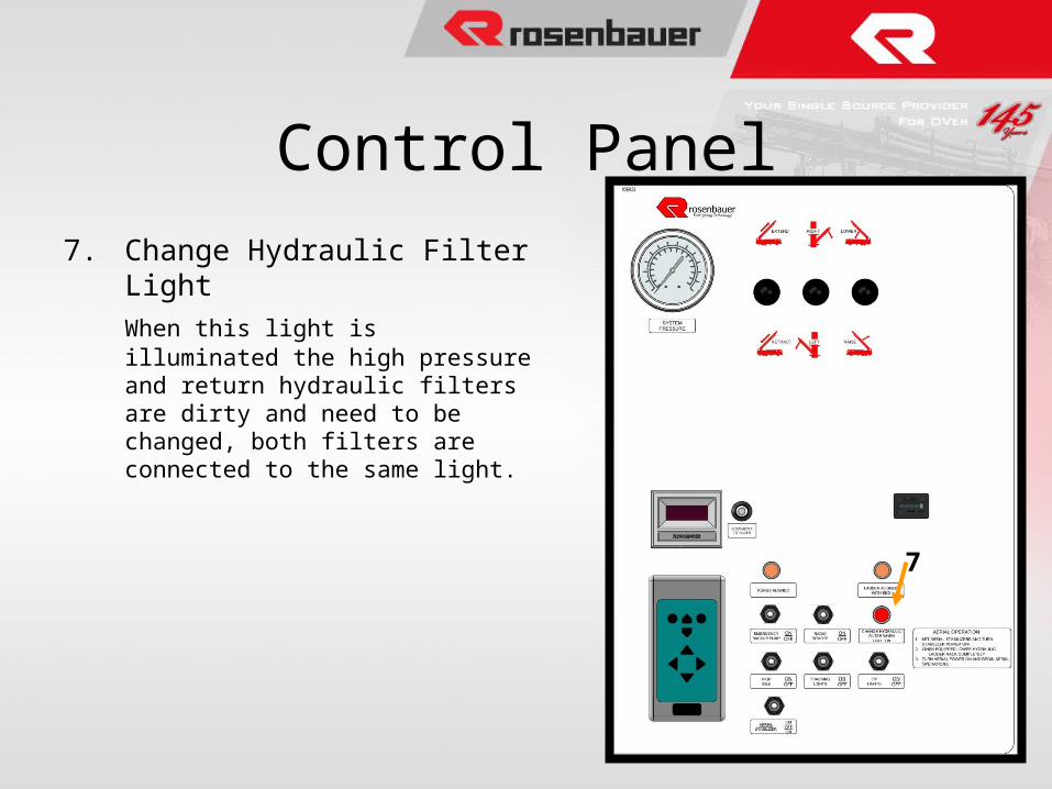
7. Change Hydraulic Filter Light
When this light is illuminated the high pressure and return hydraulic filters are dirty and need to be changed, both filters are connected to the same light.
Control Panel
7
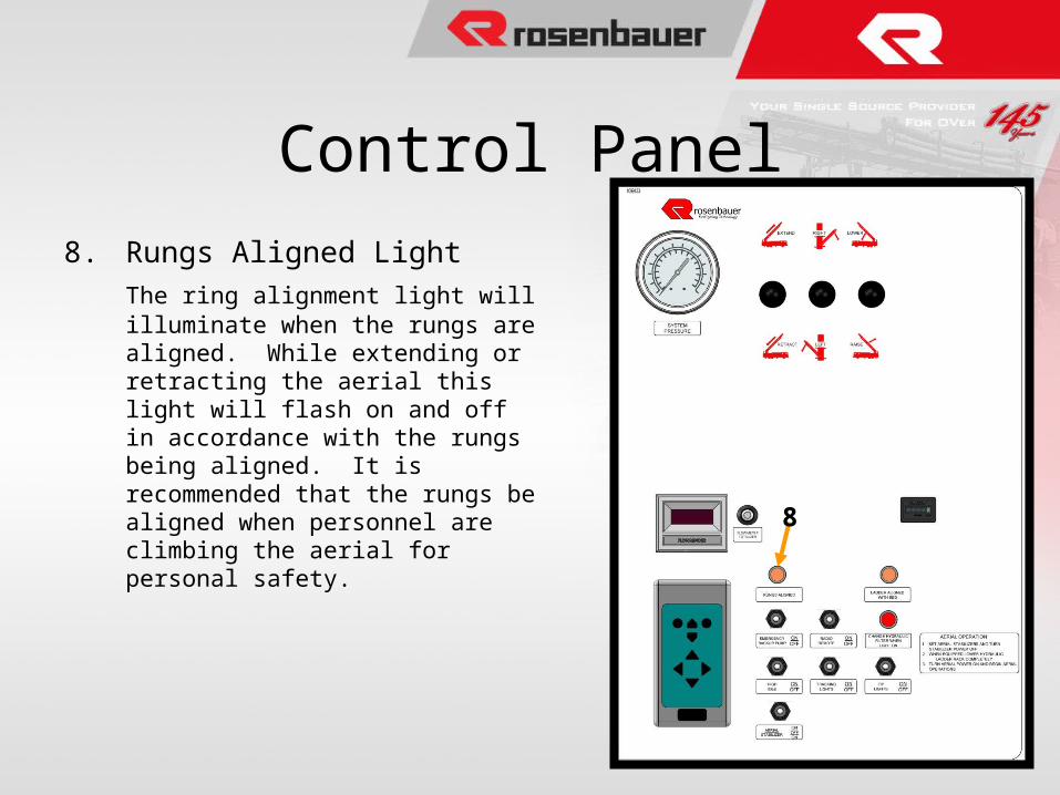
8. Rungs Aligned Light
The ring alignment light will illuminate when the rungs are aligned. While extending or retracting the aerial this light will flash on and off in accordance with the rungs being aligned. It is recommended that the rungs be aligned when personnel are climbing the aerial for personal safety.
Control Panel
8
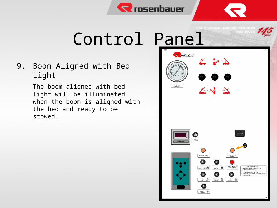
9. Boom Aligned with Bed Light
The boom aligned with bed light will be illuminated when the boom is aligned with the bed and ready to be stowed.
Control Panel
9
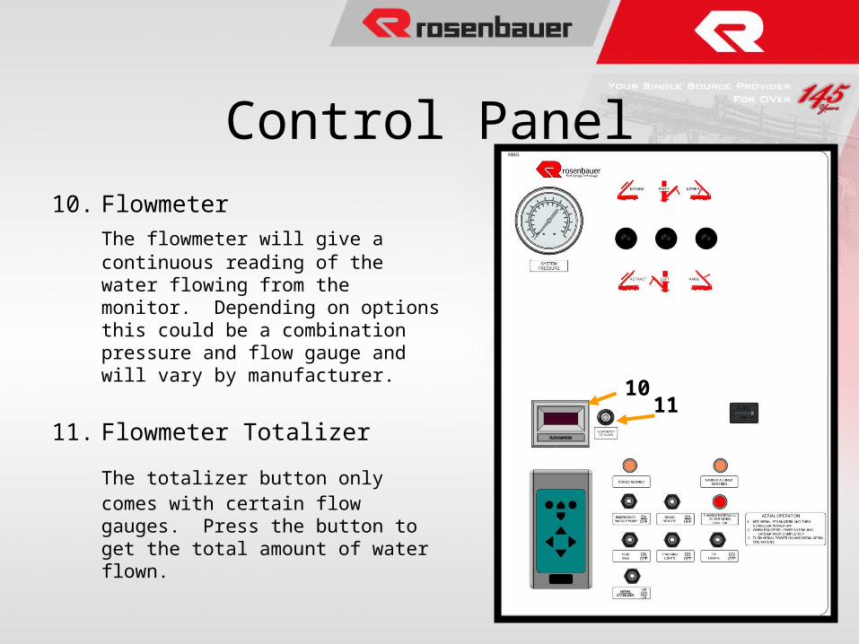
10. Flowmeter
The flowmeter will give a continuous reading of the water flowing from the monitor. Depending on options this could be a combination pressure and flow gauge and will vary by manufacturer.
11. Flowmeter Totalizer
The totalizer button only comes with certain flow gauges. Press the button to get the total amount of water flown.
Control Panel
1011
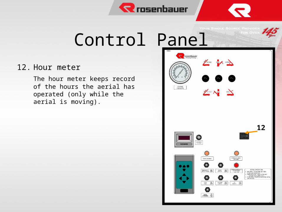
12. Hour meter
The hour meter keeps record of the hours the aerial has operated (only while the aerial is moving).
Control Panel
12
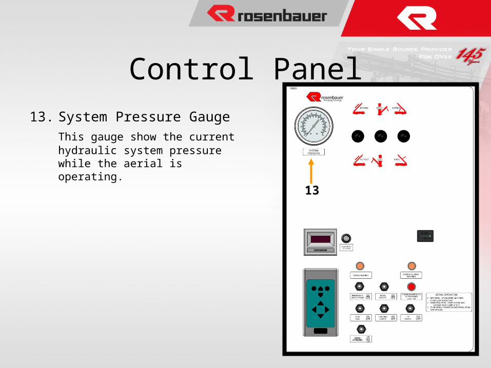
13. System Pressure Gauge
This gauge show the current hydraulic system pressure while the aerial is operating.
Control Panel
13
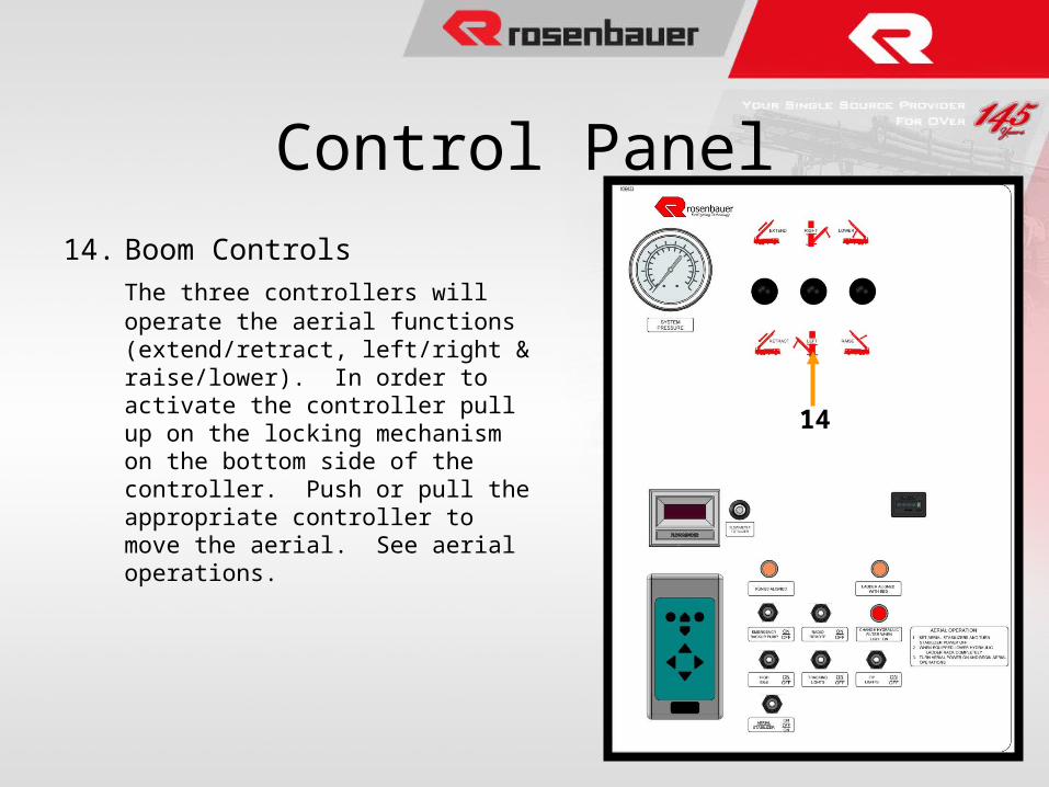
14. Boom Controls
The three controllers will operate the aerial functions (extend/retract, left/right & raise/lower). In order to activate the controller pull up on the locking mechanism on the bottom side of the controller. Push or pull the appropriate controller to move the aerial. See aerial operations.
Control Panel
14
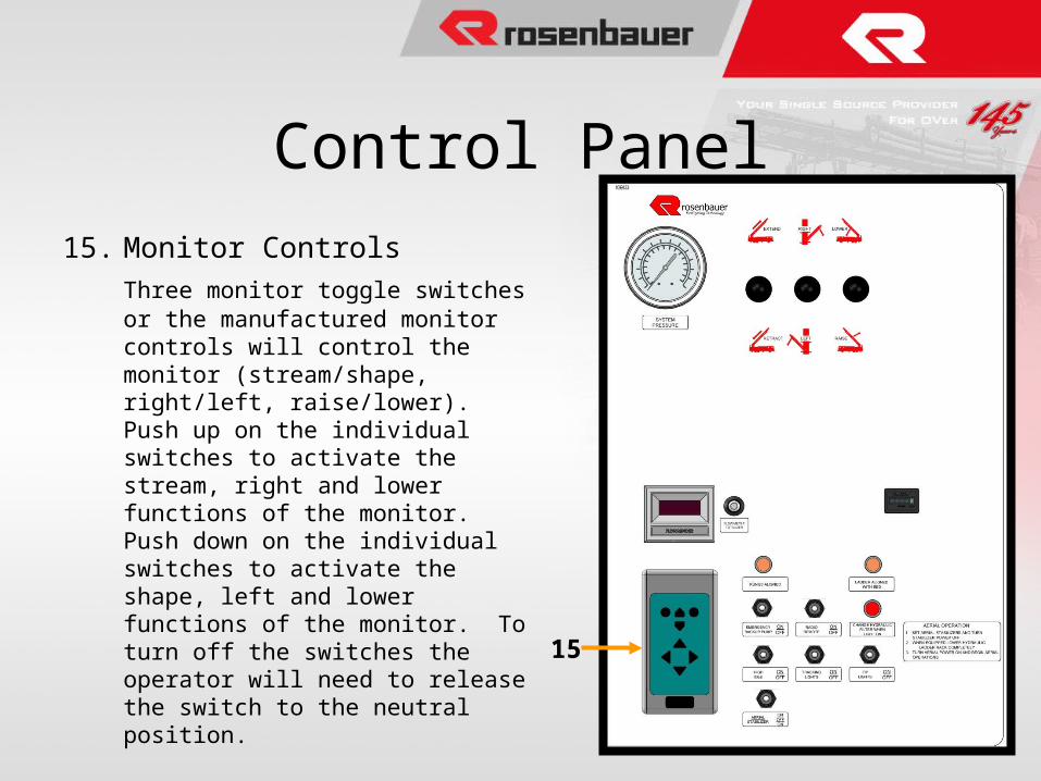
15. Monitor Controls
Three monitor toggle switches or the manufactured monitor controls will control the monitor (stream/shape, right/left, raise/lower). Push up on the individual switches to activate the stream, right and lower functions of the monitor. Push down on the individual switches to activate the shape, left and lower functions of the monitor. To turn off the switches the operator will need to release the switch to the neutral position.
Control Panel
15
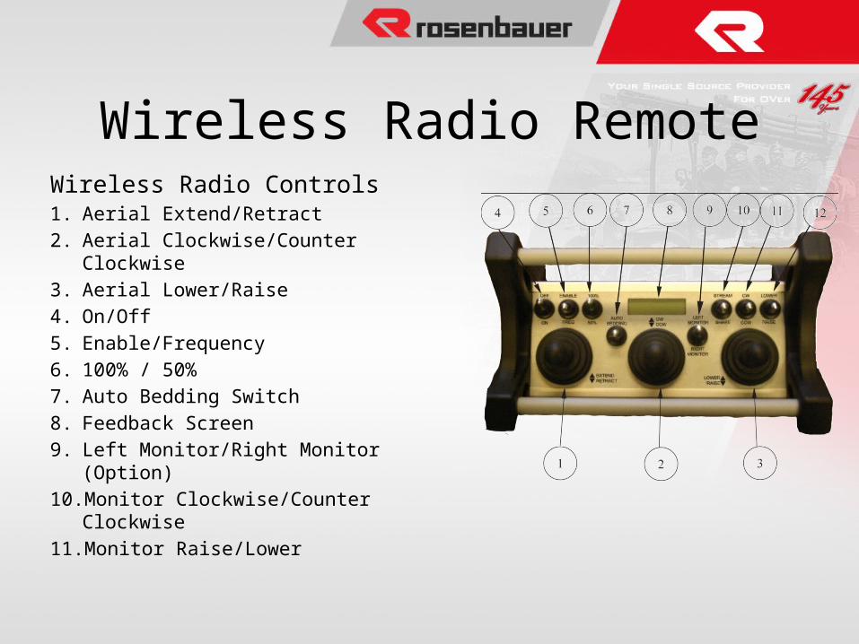
Wireless Radio Controls1. Aerial Extend/Retract
2. Aerial Clockwise/Counter Clockwise
3. Aerial Lower/Raise
4. On/Off
5. Enable/Frequency
6. 100% / 50%
7. Auto Bedding Switch
8. Feedback Screen
9. Left Monitor/Right Monitor (Option)
10. Monitor Clockwise/Counter Clockwise
11. Monitor Raise/Lower
Wireless Radio Remote
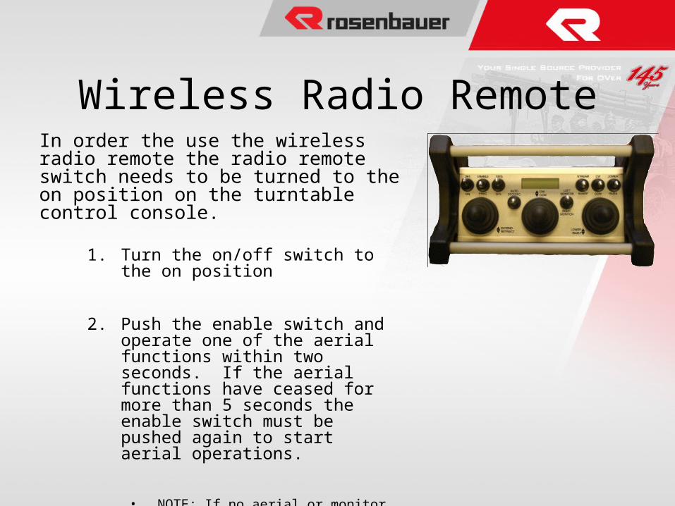
In order the use the wireless radio remote the radio remote switch needs to be turned to the on position on the turntable control console.
1. Turn the on/off switch to the on position
2. Push the enable switch and operate one of the aerial functions within two seconds. If the aerial functions have ceased for more than 5 seconds the enable switch must be pushed again to start aerial operations.
• NOTE: If no aerial or monitor operation occurs, release the enable switch and move it to the frequency side to find a new frequency and then back to enable to operate aerial or monitor function.
Wireless Radio Remote
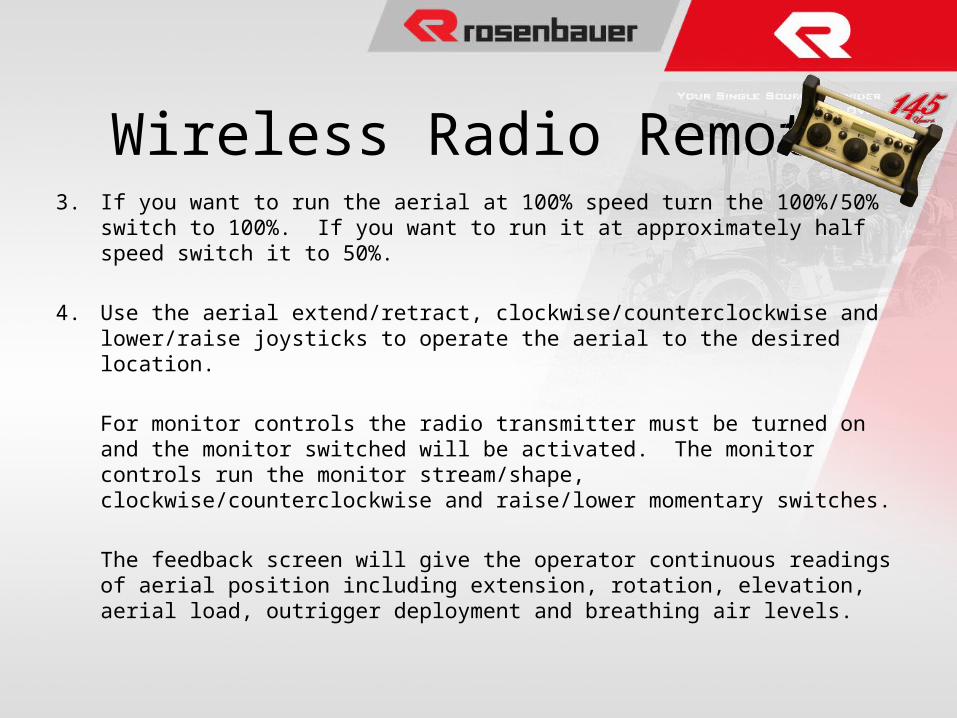
3. If you want to run the aerial at 100% speed turn the 100%/50% switch to 100%. If you want to run it at approximately half speed switch it to 50%.
4. Use the aerial extend/retract, clockwise/counterclockwise and lower/raise joysticks to operate the aerial to the desired location.
For monitor controls the radio transmitter must be turned on and the monitor switched will be activated. The monitor controls run the monitor stream/shape, clockwise/counterclockwise and raise/lower momentary switches.
The feedback screen will give the operator continuous readings of aerial position including extension, rotation, elevation, aerial load, outrigger deployment and breathing air levels.
Wireless Radio Remote
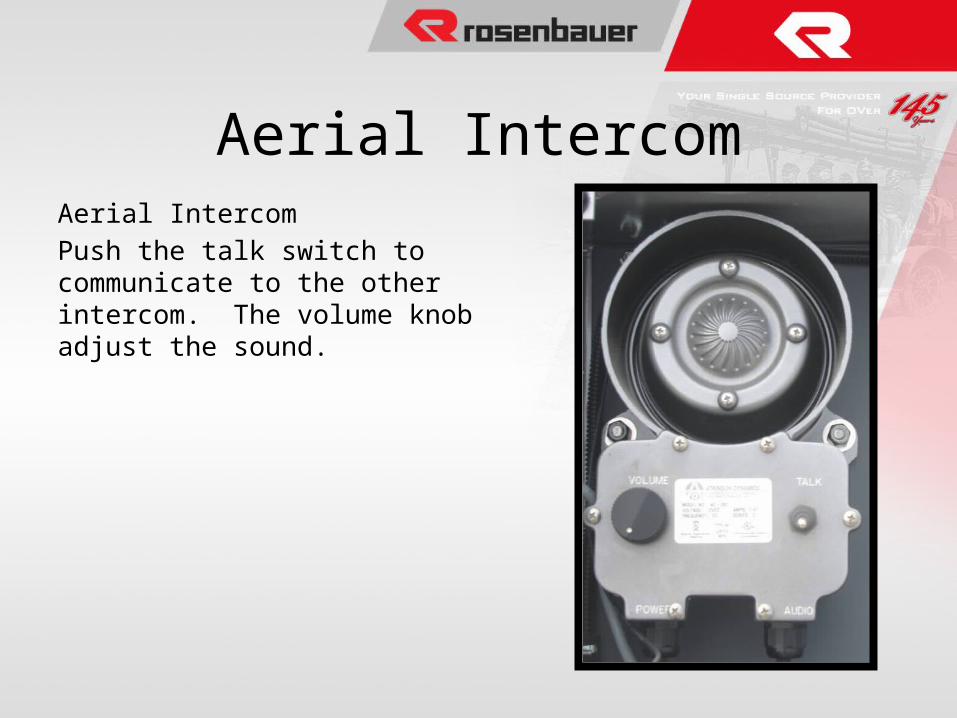
Aerial Intercom
Push the talk switch to communicate to the other intercom. The volume knob adjust the sound.
Aerial Intercom
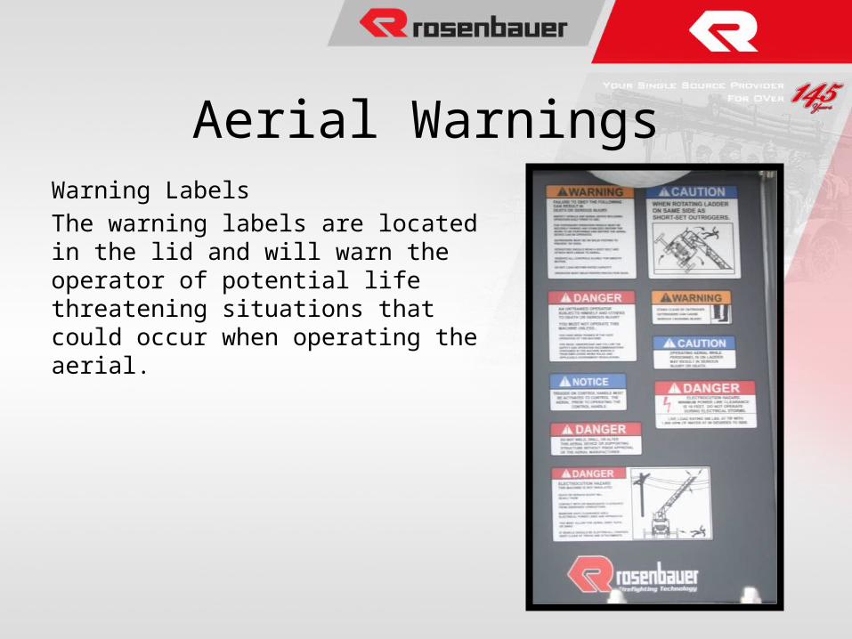
Warning Labels
The warning labels are located in the lid and will warn the operator of potential life threatening situations that could occur when operating the aerial.
Aerial Warnings
• 3 ways to use your aerial to flow water– From main pump through Aerial Devise– From external source to Aerial Devise – From main pump and use waterway inlet as a large
diameter discharge.
Water Flow
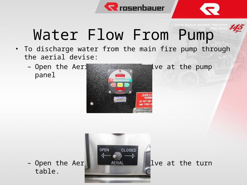
• To discharge water from the main fire pump through the aerial devise:– Open the Aerial Discharge valve at the pump panel
– Open the Aerial butterfly valve at the turn table.
Water Flow From Pump
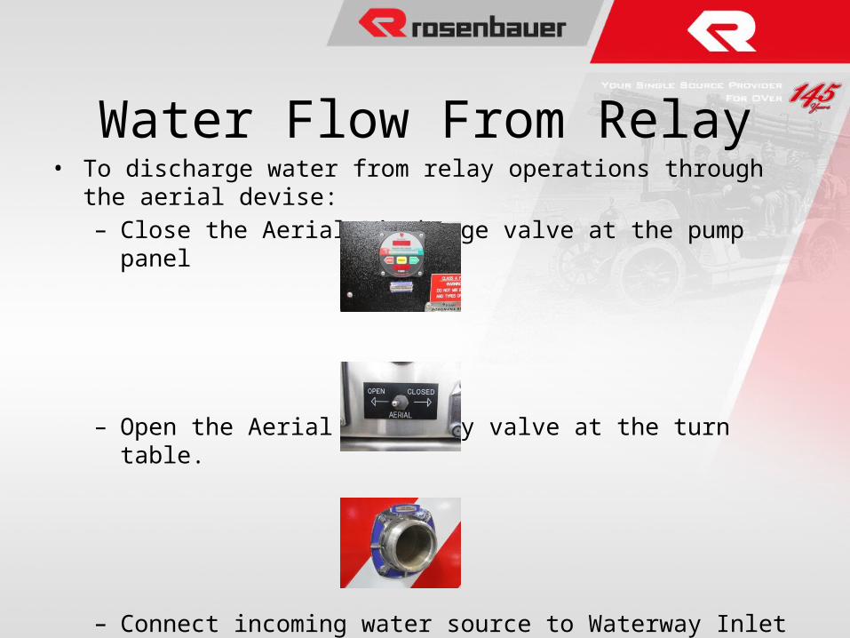
• To discharge water from relay operations through the aerial devise:– Close the Aerial Discharge valve at the pump panel
– Open the Aerial butterfly valve at the turn table.
– Connect incoming water source to Waterway Inlet at rear.
Water Flow From Relay
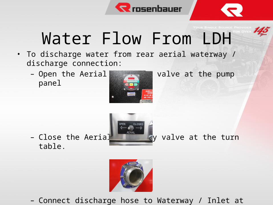
• To discharge water from rear aerial waterway / discharge connection:– Open the Aerial Discharge valve at the pump panel
– Close the Aerial butterfly valve at the turn table.
– Connect discharge hose to Waterway / Inlet at rear.
Water Flow From LDH
Practical operations of aerial to include:
1. Positioning of the truck
2. Outrigger operation, placement and setup
3. Operation of the aerial from the turn table
4. Operation of the aerial from the remote control
5. Moving water
Overview
QUESTIONS?