Embed Size (px)
Citation preview

Tech 3113
Manufacturing Tooling
Nageswara Rao Posinasetti
1. Introduction
December 2, 2015Nageswara Rao Posinasetti 2
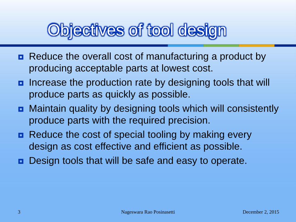
Reduce the overall cost of manufacturing a product by
producing acceptable parts at lowest cost.
Increase the production rate by designing tools that will
produce parts as quickly as possible.
Maintain quality by designing tools which will consistently
produce parts with the required precision.
Reduce the cost of special tooling by making every
design as cost effective and efficient as possible.
Design tools that will be safe and easy to operate.
December 2, 2015Nageswara Rao Posinasetti 3
Objectives of tool design
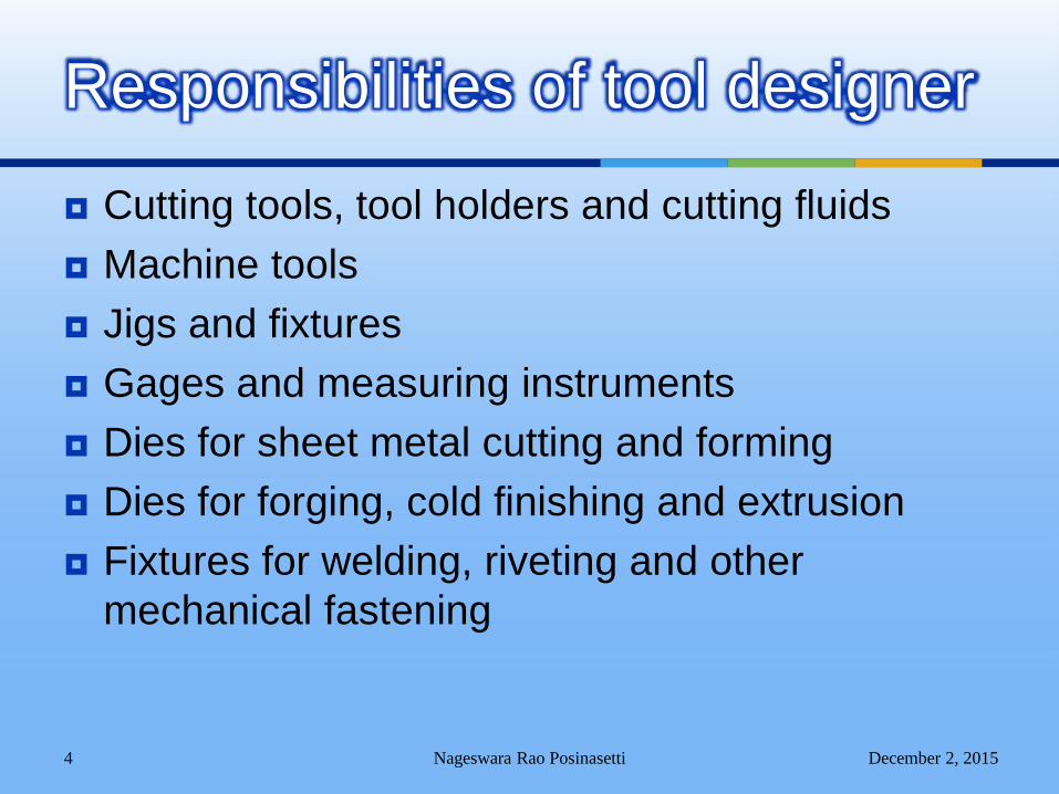
Cutting tools, tool holders and cutting fluids
Machine tools
Jigs and fixtures
Gages and measuring instruments
Dies for sheet metal cutting and forming
Dies for forging, cold finishing and extrusion
Fixtures for welding, riveting and other
mechanical fastening
December 2, 2015Nageswara Rao Posinasetti 4
Responsibilities of tool designer
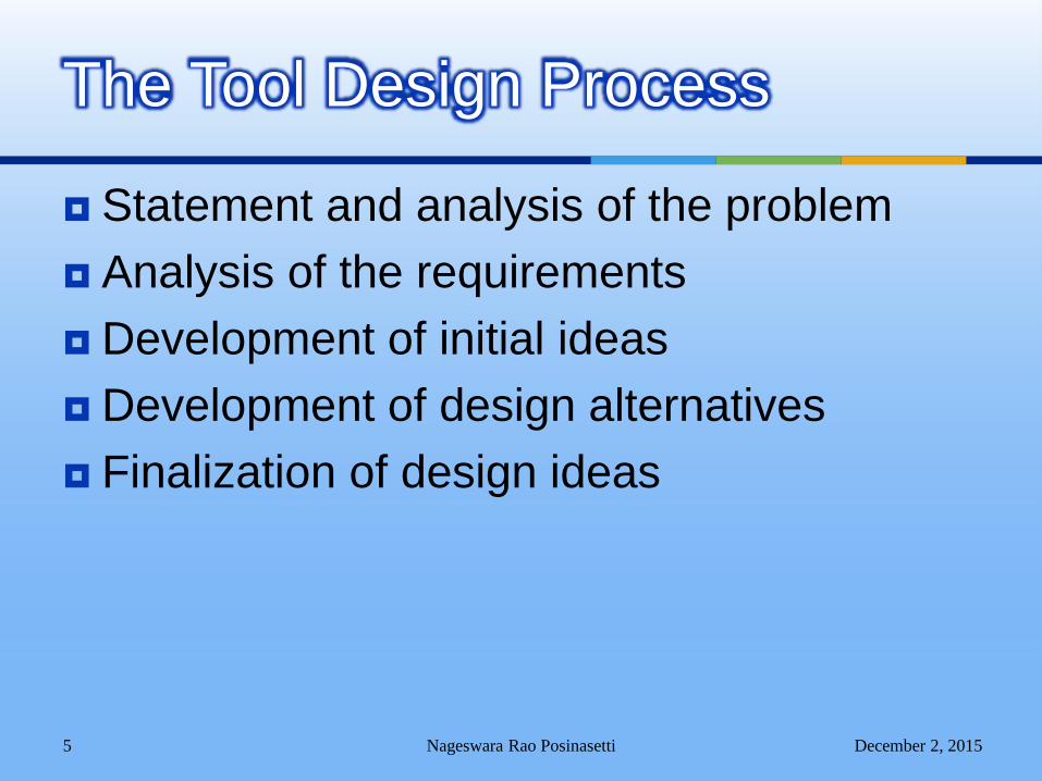
Statement and analysis of the problem
Analysis of the requirements
Development of initial ideas
Development of design alternatives
Finalization of design ideas
December 2, 2015Nageswara Rao Posinasetti 5
The Tool Design Process
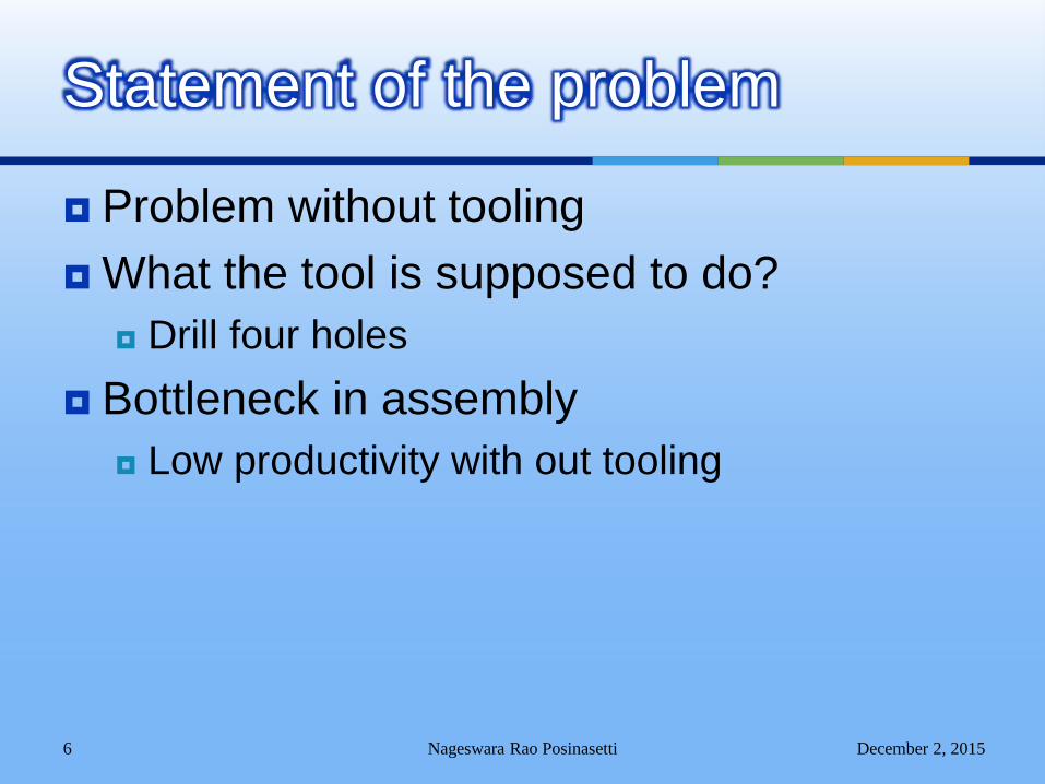
Problem without tooling
What the tool is supposed to do?
Drill four holes
Bottleneck in assembly
Low productivity with out tooling
December 2, 2015Nageswara Rao Posinasetti 6
Statement of the problem
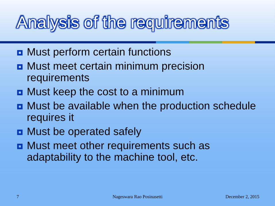
Must perform certain functions
Must meet certain minimum precision requirements
Must keep the cost to a minimum
Must be available when the production schedule requires it
Must be operated safely
Must meet other requirements such as adaptability to the machine tool, etc.
December 2, 2015Nageswara Rao Posinasetti 7
Analysis of the requirements
Estimating cost of tooling
December 2, 2015Nageswara Rao Posinasetti 8
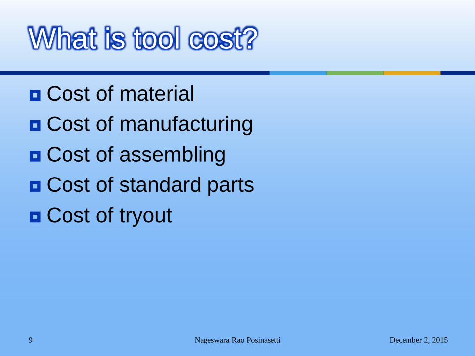
Cost of material
Cost of manufacturing
Cost of assembling
Cost of standard parts
Cost of tryout
December 2, 2015Nageswara Rao Posinasetti 9
What is tool cost?
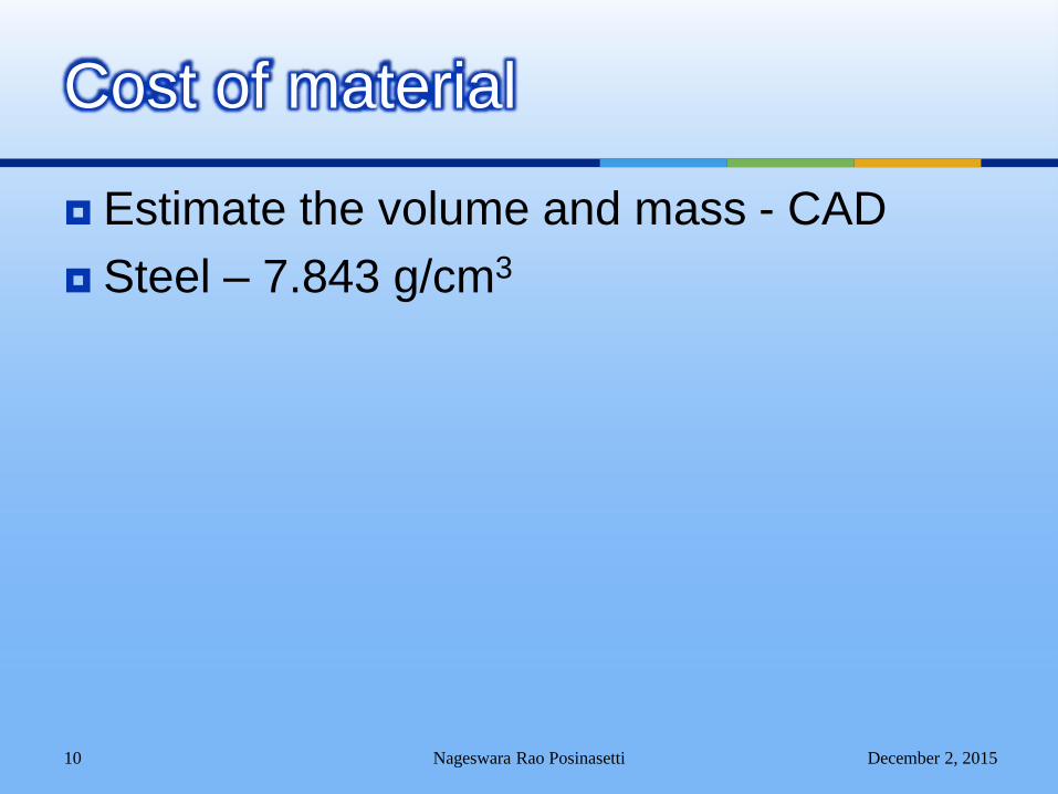
Estimate the volume and mass - CAD
Steel – 7.843 g/cm3
December 2, 2015Nageswara Rao Posinasetti 10
Cost of material

It includes
Cost of machining
Cost of heat treatment
December 2, 2015Nageswara Rao Posinasetti 11
Cost of manufacturing
December 2, 2015Nageswara Rao Posinasetti12
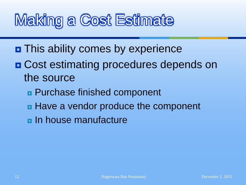
Making a Cost Estimate
This ability comes by experience
Cost estimating procedures depends on
the source
Purchase finished component
Have a vendor produce the component
In house manufacture
December 2, 2015Nageswara Rao Posinasetti13
The Cost of Machined Components
Control factors that determine the cost of
machined components are:
From what material is the component
produced?
Cost of material
Cost of scrap
Ease with which the material can be removed
(machined)
December 2, 2015Nageswara Rao Posinasetti14
The Cost of Machined Components
What type of machine is used to manufacture
the component?
Lathe, horizontal mill, vertical mill, and so on.
Cost of machine tool, tools and fixtures used
What are the major dimensions of the
component?
Size of the machine required
That determines the machine overhead cost
December 2, 2015Nageswara Rao Posinasetti15
The Cost of Machined Components
How many machined surfaces are there,
and how much material is to be removed?
Gives a good estimate of time required for
machining
How many components are made?
Fixturing requirements
Setting times and costs

December 2, 2015Nageswara Rao Posinasetti16
The Cost of Machined Components
What tolerance and surface finishes are
required?
Tighter tolerances are more expensive
What is the labor rate for machinists?
December 2, 2015Nageswara Rao Posinasetti 17
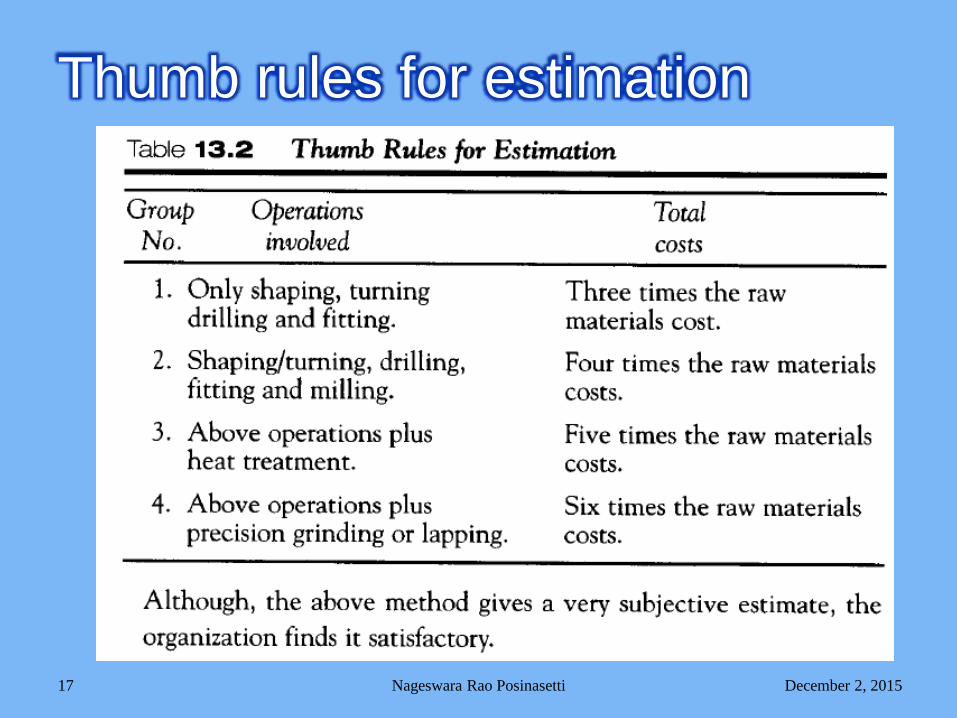
Thumb rules for estimation
This is relatively easier part.
Check with vendor.
December 2, 2015Nageswara Rao Posinasetti 18
Cost of standard parts
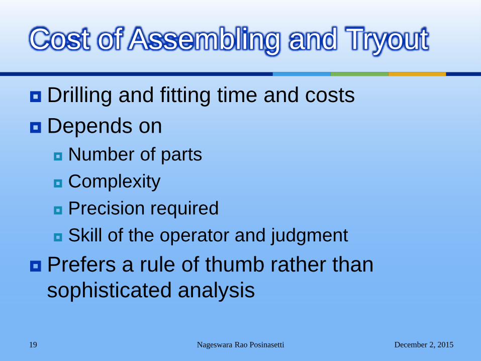
Drilling and fitting time and costs
Depends on
Number of parts
Complexity
Precision required
Skill of the operator and judgment
Prefers a rule of thumb rather than
sophisticated analysis
December 2, 2015Nageswara Rao Posinasetti 19
Cost of Assembling and Tryout
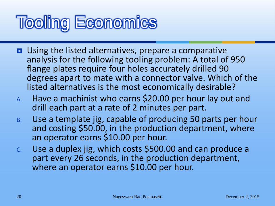
Using the listed alternatives, prepare a comparative analysis for the following tooling problem: A total of 950 flange plates require four holes accurately drilled 90 degrees apart to mate with a connector valve. Which of the listed alternatives is the most economically desirable?
A. Have a machinist who earns $20.00 per hour lay out and drill each part at a rate of 2 minutes per part.
B. Use a template jig, capable of producing 50 parts per hour and costing $50.00, in the production department, where an operator earns $10.00 per hour.
C. Use a duplex jig, which costs $500.00 and can produce a part every 26 seconds, in the production department, where an operator earns $10.00 per hour.
December 2, 2015Nageswara Rao Posinasetti 20
Tooling Economics
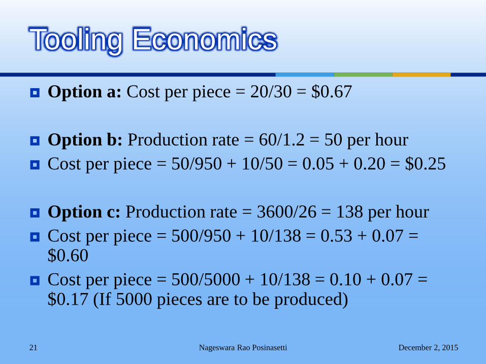
Option a: Cost per piece = 20/30 = $0.67
Option b: Production rate = 60/1.2 = 50 per hour
Cost per piece = 50/950 + 10/50 = 0.05 + 0.20 = $0.25
Option c: Production rate = 3600/26 = 138 per hour
Cost per piece = 500/950 + 10/138 = 0.53 + 0.07 = $0.60
Cost per piece = 500/5000 + 10/138 = 0.10 + 0.07 = $0.17 (If 5000 pieces are to be produced)
December 2, 2015Nageswara Rao Posinasetti 21
Tooling Economics
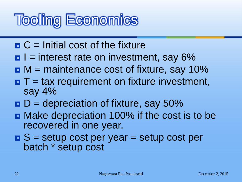
C = Initial cost of the fixture
I = interest rate on investment, say 6%
M = maintenance cost of fixture, say 10%
T = tax requirement on fixture investment, say 4%
D = depreciation of fixture, say 50%
Make depreciation 100% if the cost is to be recovered in one year.
S = setup cost per year = setup cost per batch * setup cost
December 2, 2015Nageswara Rao Posinasetti 22
Tooling Economics
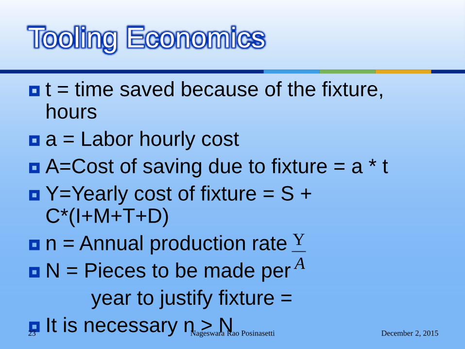
t = time saved because of the fixture, hours
a = Labor hourly cost
A=Cost of saving due to fixture = a * t
Y=Yearly cost of fixture = S + C*(I+M+T+D)
n = Annual production rate
N = Pieces to be made per
year to justify fixture =
It is necessary n > NDecember 2, 2015Nageswara Rao Posinasetti 23
Tooling Economics
A
Y
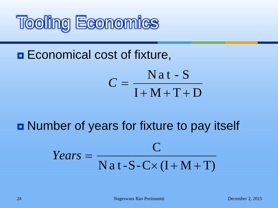
Economical cost of fixture,
Number of years for fixture to pay itself
December 2, 2015Nageswara Rao Posinasetti 24
Tooling Economics
DTMI
S-taN
C
T)M(IC-S-taN
C
Years
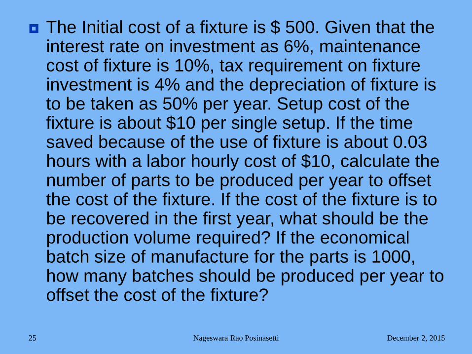
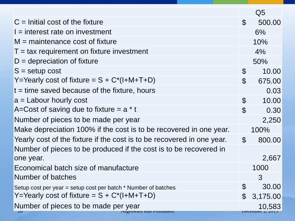
The Initial cost of a fixture is $ 500. Given that the interest rate on investment as 6%, maintenance cost of fixture is 10%, tax requirement on fixture investment is 4% and the depreciation of fixture is to be taken as 50% per year. Setup cost of the fixture is about $10 per single setup. If the time saved because of the use of fixture is about 0.03 hours with a labor hourly cost of $10, calculate the number of parts to be produced per year to offset the cost of the fixture. If the cost of the fixture is to be recovered in the first year, what should be the production volume required? If the economical batch size of manufacture for the parts is 1000, how many batches should be produced per year to offset the cost of the fixture?
December 2, 2015Nageswara Rao Posinasetti 25
December 2, 2015Nageswara Rao Posinasetti 26
Q5
C = Initial cost of the fixture $ 500.00
I = interest rate on investment 6%
M = maintenance cost of fixture 10%
T = tax requirement on fixture investment 4%
D = depreciation of fixture 50%
S = setup cost $ 10.00
Y=Yearly cost of fixture = S + C*(I+M+T+D) $ 675.00
t = time saved because of the fixture, hours 0.03
a = Labour hourly cost $ 10.00
A=Cost of saving due to fixture = a * t $ 0.30
Number of pieces to be made per year 2,250
Make depreciation 100% if the cost is to be recovered in one year. 100%
Yearly cost of the fixture if the cost is to be recovered in one year. $ 800.00
Number of pieces to be produced if the cost is to be recovered in
one year. 2,667
Economical batch size of manufacture 1000
Number of batches 3
Setup cost per year = setup cost per batch * Number of batches $ 30.00
Y=Yearly cost of fixture = S + C*(I+M+T+D) $ 3,175.00
Number of pieces to be made per year 10,583
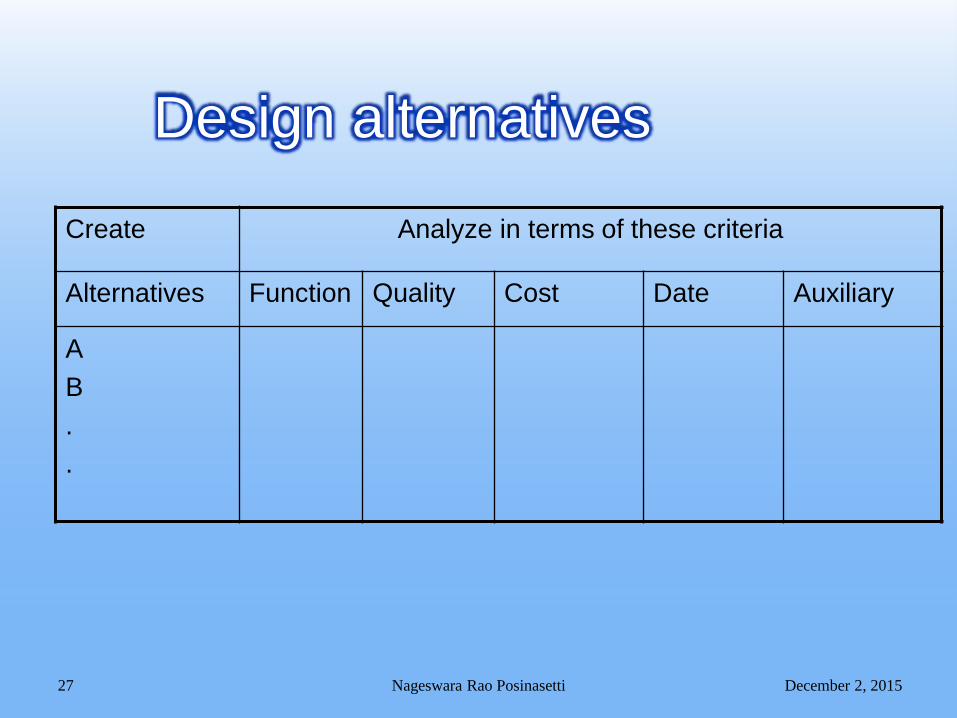
Design alternatives
Create Analyze in terms of these criteria
Alternatives Function Quality Cost Date Auxiliary
A
B
.
.
December 2, 2015Nageswara Rao Posinasetti 27
Temporary tooling
Permanent tooling
December 2, 2015Nageswara Rao Posinasetti 28
Economics of Design
Break-even charts are perhaps most
widely used to determine profits based on
anticipated sales.
They have other uses, however, such as
for selecting equipment or for measuring
the advisability of increased automation.
December 2, 2015Nageswara Rao Posinasetti 29
Break-Even Charts
To determine which of two machines is
most economical, the fixed cost and
variable cost of each machine are plotted
The total cost is composed of the sum of
the fixed and variable costs.
December 2, 2015Nageswara Rao Posinasetti 30
Break-Even Charts
Fixed cost, which relates to the initial investment on the equipment and tools required for the process.
Variable cost on the other hand varies with the actual number of objects made.
The total cost is the sum of both fixed and variable cost.
December 2, 2015Nageswara Rao Posinasetti 31
Break Even Analysis
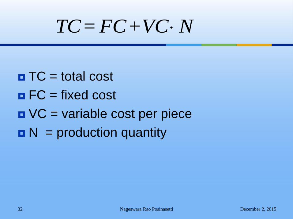
TC = total cost
FC = fixed cost
VC = variable cost per piece
N = production quantity
December 2, 2015Nageswara Rao Posinasetti 32
N VC + FC = TC
December 2, 2015Nageswara Rao Posinasetti 33
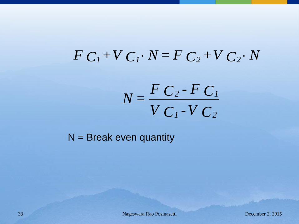
N C V + C F = N C V + C F 2211
C V - C V
C F - C F = N
21
12
N = Break even quantity
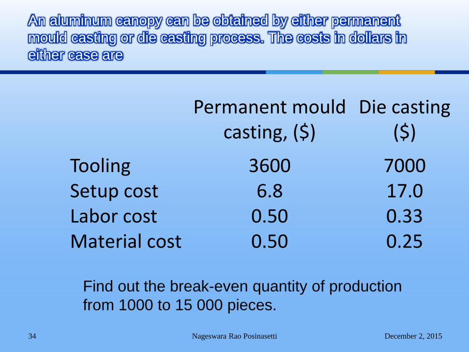
Permanent mould casting, ($)
Die casting($)
Tooling 3600 7000Setup cost 6.8 17.0Labor cost 0.50 0.33Material cost 0.50 0.25
December 2, 2015Nageswara Rao Posinasetti 34
An aluminum canopy can be obtained by either permanent
mould casting or die casting process. The costs in dollars in
either case are
Find out the break-even quantity of production
from 1000 to 15 000 pieces.
December 2, 2015Nageswara Rao Posinasetti 35
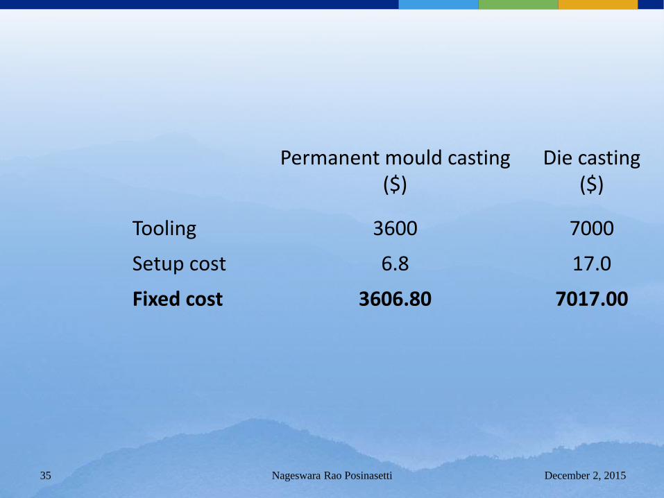
Permanent mould casting($)
Die casting($)
Tooling 3600 7000
Setup cost 6.8 17.0
Fixed cost 3606.80 7017.00
December 2, 2015Nageswara Rao Posinasetti 36
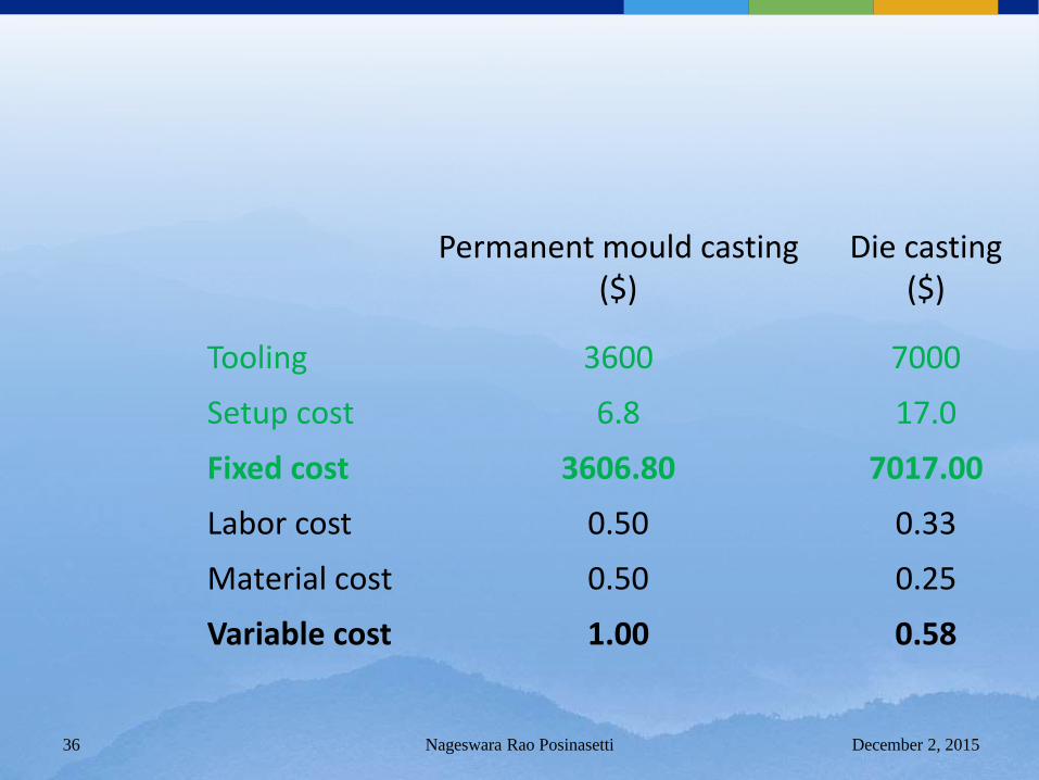
Permanent mould casting($)
Die casting($)
Tooling 3600 7000
Setup cost 6.8 17.0
Fixed cost 3606.80 7017.00
Labor cost 0.50 0.33
Material cost 0.50 0.25
Variable cost 1.00 0.58
December 2, 2015Nageswara Rao Posinasetti 37
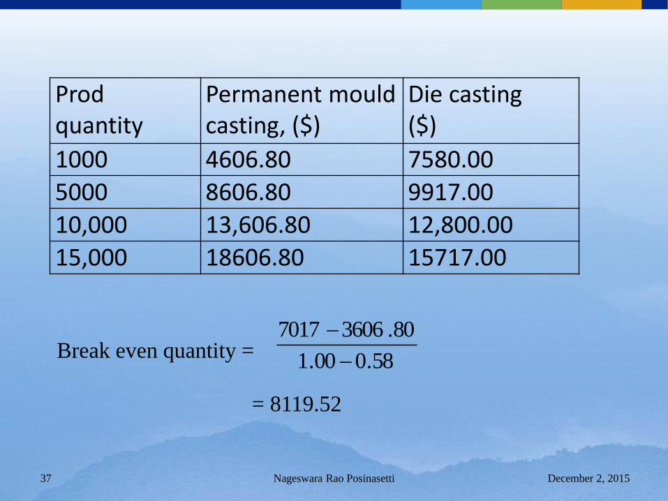
Prod quantity
Permanent mould casting, ($)
Die casting($)
1000 4606.80 7580.00
5000 8606.80 9917.00
10,000 13,606.80 12,800.00
15,000 18606.80 15717.00
Break even quantity =
= 8119.52
58.000.1
80.36067017
Draw and dimension with due consideration for
someone using the drawing to make the item in
the tool room.
Do not crowd views or dimensions.
Analyze each cut to be sure it can be done with
standard tools.
Use only as many views as necessary to show
all required detail.
December 2, 2015Nageswara Rao Posinasetti 38
Tool Drawings
Surface roughness must be specified.
Tolerances and fits peculiar to tools need special consideration. It is not economical as a rule to tolerance both details
of a pair of mating parts as is required on production part detailing.
In cases where a hole and a plug are on different details to be made and mated, the fit tolerance should be put on the male piece and the hole should carry a nominal size.
December 2, 2015Nageswara Rao Posinasetti 39
Tool Drawings
The stock list of any tool drawings should
indicate all sizes required to obtain the
right amount for each detail.
As far as possible, stock sizes known to be
on hand should be used, but in all cases,
available sizes should be specified. A proper,
finished detail is dependent upon starting with
the right material.
December 2, 2015Nageswara Rao Posinasetti 40
Tool Drawings
Use notes to convey ideas that cannot be
communicated by conventional drawing.
Heat treatments and finishes are usually
identified as specification references
rather than being spelled out on each
drawing.
December 2, 2015Nageswara Rao Posinasetti 41
Tool Drawings
Secondary operations such as surface grinding, machining of edges, polishing, heat treating, or similar specifications should be kept to a minimum.
Only employ these operations when they are important to the overall function of the tool; otherwise these operations will only add cost, not quality to the tool.
December 2, 2015Nageswara Rao Posinasetti 42
Tool Drawings
Apply tolerances realistically. Overly tight
tolerances can add a great deal of
additional cost with little or no added value
to the tool.
The function of the detail should determine
the specific tolerance, not a standard title
block tolerance value.
December 2, 2015Nageswara Rao Posinasetti 43
Tool Drawings
Layout the part in an identifying color (red
is suggested).
Layout any cutting tools. Possible
interference or other confining items
should be indicated in another identifying
color (blue suggested). Use of the cutting
tool should not damage the machine or the
fixture.
December 2, 2015Nageswara Rao Posinasetti 44
Tooling Layout
Indicate all locating requirements for the part. There are three locating planes: use three points in one, two points in the second, and only one point in the third plane.
This is called the 3-2-1 locate system. Do not locate on the parting line of castings or forgings. All locators must be accessible for simple cleaning of chips and dirt.
December 2, 2015Nageswara Rao Posinasetti 45
Tooling Layout
Indicate all clamping requirements for the part.
Be careful to avoid marking or deforming finished or delicate surfaces.
Consider the clamping movements of the operator so injury to the hands or unsafe situations are eliminated.
Be sure it is possible to load and unload the part.
December 2, 2015Nageswara Rao Posinasetti 46
Tooling Layout
Layout the details with due considerations
to stock sizes, so as to minimize
machining requirements.
Use full scale in the layout if possible.
Indicate the use of standard fixture parts
(shelf items) whenever possible.
December 2, 2015Nageswara Rao Posinasetti 47
Tooling Layout
Identify each different item or detail of any
design by the use of balloons with leaders
and arrows pointing to the detail in the
view that best shows the outline of the
item. These should not go to a line that is
common to other details.
December 2, 2015Nageswara Rao Posinasetti 48
Tooling Layout
Safety should be designed into the tooling.
Cutting should never be performed against a
clamp, because of vibration and tool chatter.
Instead, parts should be nested against pins in
order to take the cutter load.
Rigidity and fool proofing should always be built
into the tooling.
December 2, 2015Nageswara Rao Posinasetti 49
Safety as Related to Tool Design
Make drill jigs large enough to hold without the danger of spinning.
Small drill jigs should always be clamped in a vise or against a bar or backstop.
Install plexiglass guards around all milling and fIycutting operations where chips endanger workers or work areas.
December 2, 2015Nageswara Rao Posinasetti 50
Safety as Related to Tool Design

Questions?
December 2, 2015Nageswara Rao Posinasetti 51