Embed Size (px)
Citation preview
1
Safety precautions Be sure to read this Instruction Manual and appended documents thoroughly before installing, operating the inverter. Maintenance and service items in this manual are only caution related items. Read QRG (Quick Reference Guide) carefully before starting the
maintenance and service. (QRG can be downloaded from our website.) In the Instruction Manual, safety instructions are classified into two levels, namely WARNING and CAUTION.
: Indicates that incorrect handling may cause hazardous situations, which may result in serious personal injury or death. : Indicates that incorrect handling may cause hazardous situations, which may result in moderate or slight personal injury or
physical damage alone. Note that even a level situation may lead to a serious consequence according to circumstances. Be sure to follow every safety instruction, which contains important safety information. Also focus on and observe the items and instructions described under "Notes" in the text.
1. Installation
2. Wiring
Make sure that the voltage of AC power supply matches the rated voltage of your inverter. Otherwise, you run the risk of injury or fire. - Do not input single-phase power into the 3-phase inverter. Otherwise, you run the risk of fire. - Do not connect AC power supply to any of the output terminals (U, V, and W). Otherwise, you run the risk of injury or fire. - NE-S1 series inverter do not have terminals for braking resistor. Do not connect the resistor. Otherwise there is a risk of fire. - Connect an earth-leakage breaker to the power input circuit. Otherwise, you run the risk of fire. - Use only the power cables, earth-leakage breaker, and magnetic contactors that have the specified capacity (ratings). Otherwise, you run the risk
of fire. - Do not use the magnetic contactor installed on the primary and secondary sides of the inverter to stop its operation. - Tighten each screw to the specified torque. No screws must be left loose. Otherwise, you run the risk of fire. - Before operating slide switch in the inverter, be sure to turn off the power supply. Otherwise, you run the risk of electric shock and injury. - Please make sure that earth or ground screw is tightened properly and completely.
- First, check the screws of output terminal (U, V and W) are properly tighten, and then tighten the screws of input terminal (R, S and T)
Basic Manual of Hitachi NE-S1 series inverter
Thank you for purchasing the Hitachi NE-S1 series inverter. Please read this document and QRG(Quick Reference Guide), and understand perfectly how to handle properly and the safety cautions of the product before operation, for safety and proper usage. Note that this Manual is intended for each product and should be delivered to the end user of the inverter.
NT341BX
Many of the drawings in the Instruction Manual show the inverter with covers and/or parts blocking your view being removed. Do not operate the inverter in the status shown in those drawings. If you have removed the covers and/or parts, be sure to reinstall them in their original positions before starting operation, and follow all instructions in the Instruction Manual when operating the inverter.
- Install the inverter on a non-flammable surface, e.g., metal. Otherwise, you run the risk of fire. - Do not place flammable materials near the installed inverter. Otherwise, you run the risk of fire. - When carrying the inverter, do not hold its top cover. Otherwise, you run the risk of injury and damage by dropping the inverter. - Prevent foreign matter (e.g., cut pieces of wire, sputtering welding materials, iron chips, wire, and dust) from entering the inverter. Otherwise, you
run the risk of fire. - Install the inverter on a structure able to bear the weight specified in the Instruction Manual. Otherwise, you run the risk of injury due to the
inverter falling. - Install the inverter on a vertical wall that is free of vibrations. Otherwise, you run the risk of injury due to the inverter falling. - Do not install and operate the inverter if it is damaged or its parts are missing. Otherwise, you run the risk of injury. - Install the inverter in a well-ventilated indoor site not exposed to direct sunlight. Avoid places where the inverter is exposed to high temperature,
high humidity, condensation, dust, explosive gases, corrosive gases, flammable gases, grinding fluid mist, or salt water. Otherwise, you run the risk of fire.
- The inverter is precision equipment. Do not allow it to fall or be subject to high impacts, step on it, or place a heavy load on it. Doing so may cause the inverter to fail.
- Be sure to ground the inverter. Otherwise, you run the risk of electric shock or fire. - Commit wiring work to a qualified electrician. Otherwise, you run the risk of electric shock or fire. - Before wiring, make sure that the power supply is off. Otherwise, you run the risk of electric shock or fire. - Perform wiring only after installing the inverter. Otherwise, you run the risk of electric shock or injury. - The inverter must be powered OFF before you change any of the slide switch settings. Otherwise, you run the risk of electric shock or injury.
CAUTION
WARNING
CAUTION
WARNING
CAUTION
CAUTION
CAUTION
2
3. Operation
4. Maintenance, inspection, and parts replacement
5. Others
- While power is supplied to the inverter, do not touch any terminal or internal part of the inverter, check signals, or connect or disconnect any wire or connector. Otherwise, you run the risk of electric shock or fire.
- Be sure to close the top cover before turning on the inverter power. Do not open the top while power is being supplied to the inverter or voltage remains inside. Otherwise, you run the risk of electric shock.
- Do not operate switches with wet hands. Otherwise, you run the risk of electric shock. - While power is supplied to the inverter, do not touch the terminal of the inverter, even if it has stopped. Otherwise, you run the risk of injury or fire. - If the retry mode has been selected, the inverter will restart suddenly after a break in the tripping status. Stay away from the machine controlled by
the inverter when the inverter is under such circumstances. (Design the machine so that human safety can be ensured, even when the inverter restarts suddenly.) Otherwise, you run the risk of injury.
- Do not select the retry mode for controlling an elevating or traveling device because output free-running status occurs in retry mode. Otherwise, you run the risk of injury or damage to the machine controlled by the inverter.
- If an operation command has been input to the inverter before a short-term power failure, the inverter may restart operation after the power recovery. If such a restart may put persons in danger, design a control circuit that disables the inverter from restarting after power recovery. Otherwise, you run the risk of injury.
- Prepare the additional emergency stop switch in addition to the stop key of the integrated operator and/or the optional operator. Otherwise,
there is a danger of injury. - If an operation command has been input to the inverter before the inverter enters alarm status, the inverter will restart suddenly when the alarm
status is reset. Before resetting the alarm status, make sure that no operation command has been input. - While power is supplied to the inverter, do not touch any internal part of the inverter or insert a bar in it. Otherwise, you run the risk of
electric shock or fire. - Run/Stop/Reset is integrated in one button, before you press the button. Please make sure that the machine (facility) can be operated.
Otherwise, you run the risk of injury or damage to the machine controlled by the inverter.
- Do not touch the heat sink, which heats up during the inverter operation. Otherwise, you run the risk of burn injury. - The inverter allows you to easily control the speed of motor or machine operations. Before operating the inverter, confirm the capacity and ratings
of the motor or machine controlled by the inverter. Otherwise, you run the risk of injury. - Install an external brake system if needed. Otherwise, you run the risk of injury. - When using the inverter to operate a standard motor at a frequency of over 60 Hz, check the allowable motor speeds with the manufacturers of the
motor and the machine to be driven and obtain their consent before starting inverter operation. Otherwise, you run the risk of damage to the motor and machine.
- During inverter operation, check the motor for the direction of rotation, abnormal sound, and vibrations. Otherwise, you run the risk of damage to the machine driven by the motor.
- Regardless Run command setting (A002/A202), if the key is pressed, the inverter starts running. Therefore, if you selected Run command such as operator or terminal, please handle the key after you made sure that the machine/facility can be operated safely.
- Before inspecting the inverter, be sure to turn off the power supply and wait for 10 minutes or more. Otherwise, you run the risk of electric shock. (Before inspection, confirm that the Charge lamp on the inverter is off.) In case the power indication of the operator does not turn ON after power-up, inverter may be damaged. In that case, the inspection must be done
after waiting two hours or more of the power OFF. Otherwise there is a danger of electric shock and/or injury. - Commit only a designated person to maintenance, inspection, and the replacement of parts. (Be sure to remove wristwatches and metal accessories, e.g., bracelets, before maintenance and inspection work and to use insulated tools for the work.) Otherwise, you run the risk of electric shock and injury.
- Never modify the inverter. Otherwise, you run the risk of electric shock and injury. Do not discard the inverter with household waste. Contact an industrial waste management company in your area who can treat industrial waste without polluting the environment.
- Do not discard the inverter with household waste. Contact an industrial waste management company in your area who can treat industrial waste without polluting the environment.
CAUTION
WARNING
WARNING
WARNING
CAUTION
3
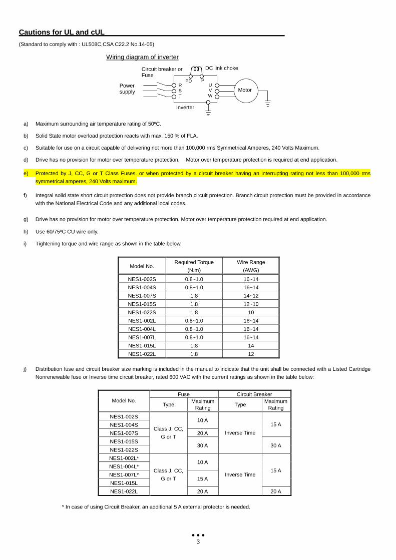
Cautions for UL and cUL (Standard to comply with : UL508C,CSA C22.2 No.14-05)
a) Maximum surrounding air temperature rating of 50ºC.
b) Solid State motor overload protection reacts with max. 150 % of FLA.
c) Suitable for use on a circuit capable of delivering not more than 100,000 rms Symmetrical Amperes, 240 Volts Maximum.
d) Drive has no provision for motor over temperature protection. Motor over temperature protection is required at end application.
e) Protected by J, CC, G or T Class Fuses. or when protected by a circuit breaker having an interrupting rating not less than 100,000 rms
symmetrical amperes, 240 Volts maximum.
f) Integral solid state short circuit protection does not provide branch circuit protection. Branch circuit protection must be provided in accordance
with the National Electrical Code and any additional local codes.
g) Drive has no provision for motor over temperature protection. Motor over temperature protection required at end application.
h) Use 60/75ºC CU wire only.
i) Tightening torque and wire range as shown in the table below.
Model No.
Required Torque
(N.m)
Wire Range
(AWG)
NES1-002S 0.8~1.0 16~14
NES1-004S 0.8~1.0 16~14
NES1-007S 1.8 14~12
NES1-015S 1.8 12~10
NES1-022S 1.8 10
NES1-002L 0.8~1.0 16~14
NES1-004L 0.8~1.0 16~14
NES1-007L 0.8~1.0 16~14
NES1-015L 1.8 14
NES1-022L 1.8 12
j) Distribution fuse and circuit breaker size marking is included in the manual to indicate that the unit shall be connected with a Listed Cartridge
Nonrenewable fuse or Inverse time circuit breaker, rated 600 VAC with the current ratings as shown in the table below:
Fuse Circuit Breaker
Model No. Type
Maximum Rating
Type Maximum
Rating
NES1-002S
NES1-004S 10 A
NES1-007S 20 A
15 A
NES1-015S
NES1-022S
Class J, CC,
G or T
30 A
Inverse Time
30 A
NES1-002L*
NES1-004L* 10 A
NES1-007L*
NES1-015L 15 A
15 A
NES1-022L
Class J, CC,
G or T
20 A
Inverse Time
20 A
* In case of using Circuit Breaker, an additional 5 A external protector is needed.
PD R S T
U V W
P
Inverter
Power supply Motor
DC link choke Circuit breaker or Fuse
Wiring diagram of inverter
4
Supplement of Cautions for UL and cUL Note (* mark) of item j): When a breaker is used in NES1-002L/004L/007L, a breaker of 15A and a protector (breaker) of 5A in series is additionally
required by the NEC(National Electrical code) standard un US.
1.1 Inspection at unpacking
Please check the followings after unpacking.
Please contact Hitachi if there are any problems such as noted below on the product.
(1) Any damage during transportation?
(2) Basic manual (English and Japanese) are packed together with the product?
(3) The product is the one you ordered (check with the specification label)
1.2 Basic Manual (This document)
This Basic manual is for NE-S1 series inverters.
Read this manual carefully for the proper operation of the product. Please keep this manual for future usage.
Please refer to QRG for the further detailed information. QRG can be downloaded from our website.
HP address: http://www.hitachi-ies.co.jp/english/products/inv/nes1/index.htm
When you use any options, please refer to the manual of each option.
1.3 In case of contact
When contacting the store or vendor where you bought the product or Hitachi directly, please provide the following information.
(1) Model name of the inverter
(2) Manufacturing number
(3) When you bought the product
(4) Contents of your inquiry
- Damaged portion and condition, and else
1.4 Warranty Terms
The warranty period under normal installation and handling conditions shall be two (2) years from the date of manufacture, or one (1) year from the
date of installation, whichever occurs first. The warranty shall cover the repair or replacement, at Hitachi's sole discretion, of ONLY the inverter that was
installed.
1. Service in the following cases, even within the warranty period, shall be charged to the purchaser:
a. Malfunction or damage caused by mis-operation or modification or improper repair
b. Malfunction or damage caused by a drop after purchase and transportation
c. Malfunction or damage caused by fire, earthquake, flood, lightening, abnormal input voltage, contamination, or other natural disasters
2. When service is required for the product at your work site, all expenses associated with field repair shall be charged to the purchaser.
3. Always keep this manual handy; please do not lose it. Please contact your Hitachi distributor to purchase replacement or additional manuals.
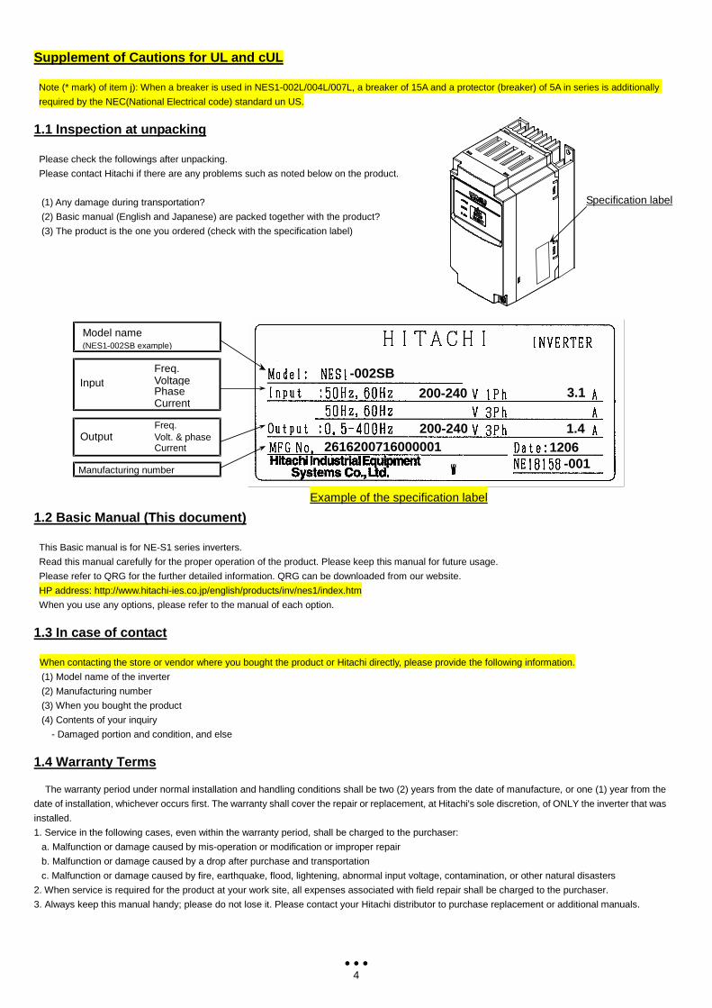
-002SB
200-240
200-240
3.1
1.4 2616200716000001 1206
-001
Example of the specification label
Model name (NES1-002SB example)
Manufacturing number
Freq. Input Voltage
Phase Current
Freq. Output Volt. & phase
Current
Specification label
5
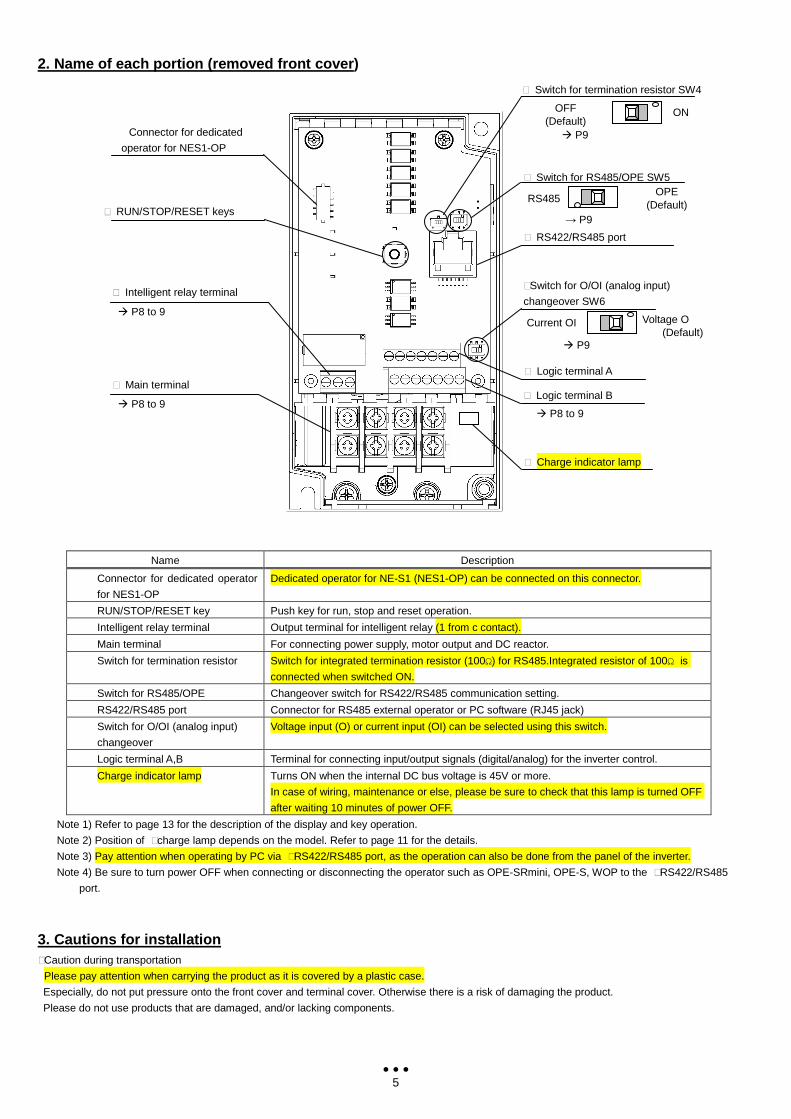
2. Name of each portion (removed front cover )
Name Description
Connector for dedicated operator
for NES1-OP
Dedicated operator for NE-S1 (NES1-OP) can be connected on this connector.
RUN/STOP/RESET key Push key for run, stop and reset operation.
Intelligent relay terminal Output terminal for intelligent relay (1 from c contact).
Main terminal For connecting power supply, motor output and DC reactor.
Switch for termination resistor Switch for integrated termination resistor (100Ω) for RS485.Integrated resistor of 100Ω is
connected when switched ON.
Switch for RS485/OPE Changeover switch for RS422/RS485 communication setting.
RS422/RS485 port Connector for RS485 external operator or PC software (RJ45 jack)
Switch for O/OI (analog input)
changeover
Voltage input (O) or current input (OI) can be selected using this switch.
Logic terminal A,B Terminal for connecting input/output signals (digital/analog) for the inverter control.
Charge indicator lamp Turns ON when the internal DC bus voltage is 45V or more.
In case of wiring, maintenance or else, please be sure to check that this lamp is turned OFF
after waiting 10 minutes of power OFF.
Note 1) Refer to page 13 for the description of the display and key operation.
Note 2) Position of ⑩charge lamp depends on the model. Refer to page 11 for the details.
Note 3) Pay attention when operating by PC via ⑩RS422/RS485 port, as the operation can also be done from the panel of the inverter.
Note 4) Be sure to turn power OFF when connecting or disconnecting the operator such as OPE-SRmini, OPE-S, WOP to the ⑩RS422/RS485
port.
3. Cautions for installation ⑩Caution during transportation
Please pay attention when carrying the product as it is covered by a plastic case.
Especially, do not put pressure onto the front cover and terminal cover. Otherwise there is a risk of damaging the product.
Please do not use products that are damaged, and/or lacking components.
⑩ Switch for RS485/OPE SW5
⑩ Switch for termination resistor SW4
⑩ RS422/RS485 port
⑩ RUN/STOP/RESET keys
⑩ Main terminal ⑩ Logic terminal A
P8 to 9
⑩Switch for O/OI (analog input)
changeover SW6
⑩ Logic terminal B
⑩ Intelligent relay terminal
⑩ Charge indicator lamp
Connector for dedicated
operator for NES1-OP
P8 to 9
OFF (Default)
ON
P9
RS485 OPE
(Default)
→ P9
Voltage O (Default)
Current OI
P9
P8 to 9
6
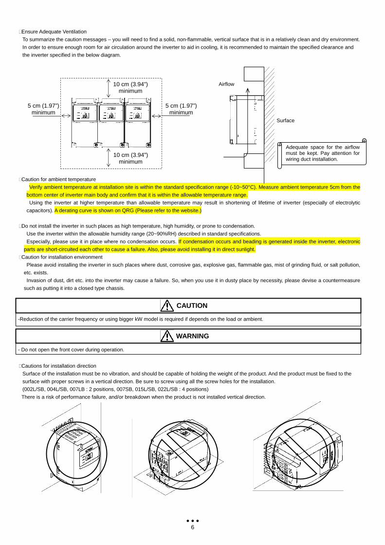
⑩Ensure Adequate Ventilation
To summarize the caution messages – you will need to find a solid, non-flammable, vertical surface that is in a relatively clean and dry environment.
In order to ensure enough room for air circulation around the inverter to aid in cooling, it is recommended to maintain the specified clearance and
the inverter specified in the below diagram.
⑩Caution for ambient temperature
Verify ambient temperature at installation site is within the standard specification range (-10~50°C). Measure ambient temperature 5cm from the
bottom center of inverter main body and confirm that it is within the allowable temperature range.
Using the inverter at higher temperature than allowable temperature may result in shortening of lifetime of inverter (especially of electrolytic
capacitors). A derating curve is shown on QRG (Please refer to the website.)
⑩Do not install the inverter in such places as high temperature, high humidity, or prone to condensation.
Use the inverter within the allowable humidity range (20~90%RH) described in standard specifications.
Especially, please use it in place where no condensation occurs. If condensation occurs and beading is generated inside the inverter, electronic
parts are short-circuited each other to cause a failure. Also, please avoid installing it in direct sunlight.
⑩Caution for installation environment
Please avoid installing the inverter in such places where dust, corrosive gas, explosive gas, flammable gas, mist of grinding fluid, or salt pollution,
etc. exists.
Invasion of dust, dirt etc. into the inverter may cause a failure. So, when you use it in dusty place by necessity, please devise a countermeasure
such as putting it into a closed type chassis.
⑩Cautions for installation direction
Surface of the installation must be no vibration, and should be capable of holding the weight of the product. And the product must be fixed to the
surface with proper screws in a vertical direction. Be sure to screw using all the screw holes for the installation.
(002L/SB, 004L/SB, 007LB : 2 positions, 007SB, 015L/SB, 022L/SB : 4 positions)
There is a risk of performance failure, and/or breakdown when the product is not installed vertical direction.
Adequate space for the airflow must be kept. Pay attention for wiring duct installation.
Surface
Airflow
5 cm (1.97”) minimum
5 cm (1.97”) minimum
10 cm (3.94”) minimum
10 cm (3.94”) minimum
- Do not open the front cover during operation.
WARNING
-Reduction of the carrier frequency or using bigger kW model is required if depends on the load or ambient.
CAUTION
7
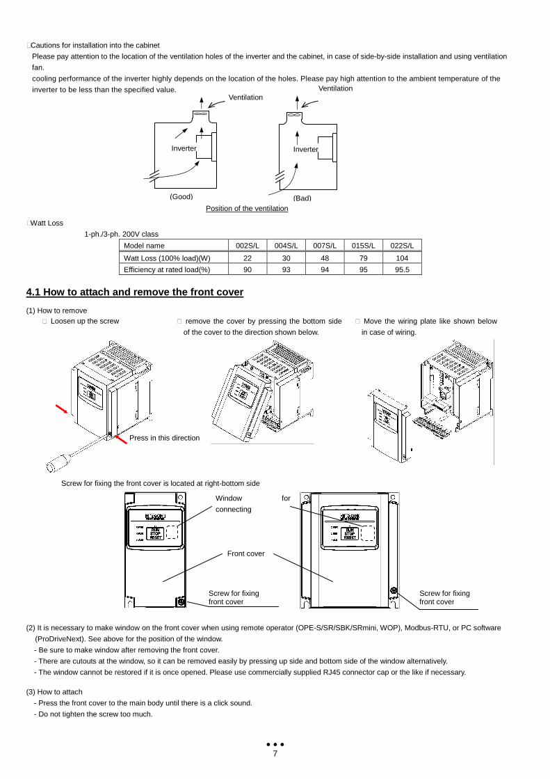
⑩Cautions for installation into the cabinet
Please pay attention to the location of the ventilation holes of the inverter and the cabinet, in case of side-by-side installation and using ventilation
fan.
cooling performance of the inverter highly depends on the location of the holes. Please pay high attention to the ambient temperature of the
inverter to be less than the specified value.
⑩Watt Loss
1-ph./3-ph. 200V class
Model name 002S/L 004S/L 007S/L 015S/L 022S/L
Watt Loss (100% load)(W) 22 30 48 79 104
Efficiency at rated load(%) 90 93 94 95 95.5
4.1 How to attach and remove the front cover (1) How to remove (2) It is necessary to make window on the front cover when using remote operator (OPE-S/SR/SBK/SRmini, WOP), Modbus-RTU, or PC software
(ProDriveNext). See above for the position of the window.
- Be sure to make window after removing the front cover.
- There are cutouts at the window, so it can be removed easily by pressing up side and bottom side of the window alternatively.
- The window cannot be restored if it is once opened. Please use commercially supplied RJ45 connector cap or the like if necessary. (3) How to attach
- Press the front cover to the main body until there is a click sound.
- Do not tighten the screw too much.
⑩ Loosen up the screw ⑩ remove the cover by pressing the bottom side
of the cover to the direction shown below.
⑩ Move the wiring plate like shown below
in case of wiring.
Screw for fixing the front cover is located at right-bottom side
Press in this direction
Ventilation
Position of the ventilation
(Good)
Ventilation
Inverter
(Bad)
Inverter
Screw for fixing front cover
Front cover
Window for
connecting
RS422/RS485
Screw for fixing front cover
8
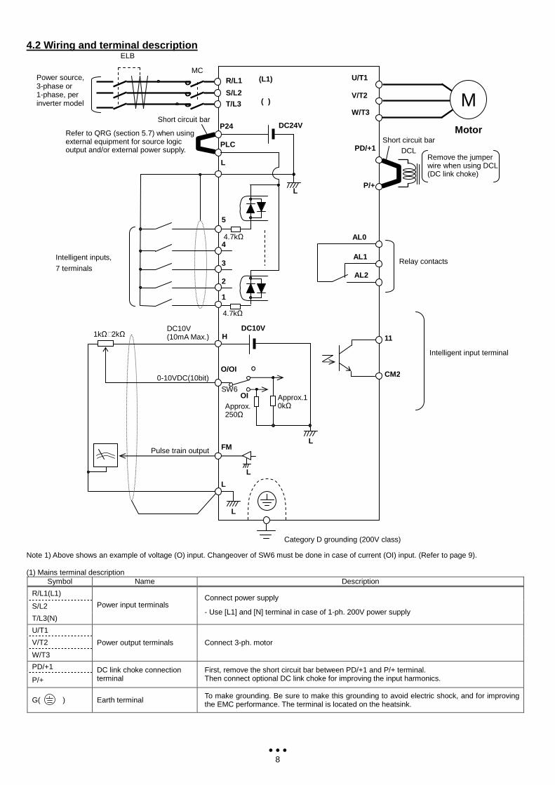
4.2 Wiring and terminal description Note 1) Above shows an example of voltage (O) input. Changeover of SW6 must be done in case of current (OI) input. (Refer to page 9). (1) Mains terminal description
Symbol Name Description
R/L1(L1)
S/L2
T/L3(N)
Power input terminals Connect power supply
- Use [L1] and [N] terminal in case of 1-ph. 200V power supply
U/T1
V/T2
W/T3
Power output terminals Connect 3-ph. motor
PD/+1
P/+ DC link choke connection terminal
First, remove the short circuit bar between PD/+1 and P/+ terminal. Then connect optional DC link choke for improving the input harmonics.
G( ) Earth terminal To make grounding. Be sure to make this grounding to avoid electric shock, and for improving the EMC performance. The terminal is located on the heatsink.
Intelligent inputs,
7 terminals
0-10VDC(10bit)
PLC
P24 DC24V
L
P/+
H
O/OI
Category D grounding (200V class)
DC10V
5
2
1
3
4
Intelligent input terminal
11
CM2
Relay contacts
AL0
AL1
AL2
L
DC10V (10mA Max.)
4.7kΩ
4.7kΩ
L FM
L
Pulse train output
L
L
PD/+1
Refer to QRG (section 5.7) when using external equipment for source logic output and/or external power supply.
Short circuit bar
Short circuit bar
DCL Remove the jumper wire when using DCL (DC link choke)
ELB
1kΩ⑩2kΩ
(L1)
()
Approx. 250Ω
O
OI SW6
Motor
U/T1
V/T2
W/T3 M
Power source, 3-phase or 1-phase, per inverter model
R/L1
S/L2 T/L3
MC
Approx.10kΩ
9
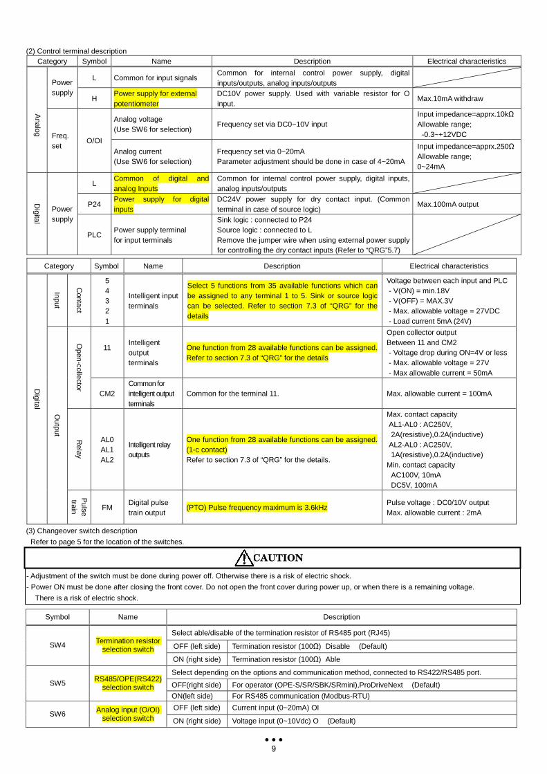
(2) Control terminal description Category Symbol Name Description Electrical characteristics
L Common for input signals Common for internal control power supply, digital inputs/outputs, analog inputs/outputs
Power supply
H Power supply for external potentiometer
DC10V power supply. Used with variable resistor for O input.
Max.10mA withdraw
Analog voltage (Use SW6 for selection)
Frequency set via DC0~10V input Input impedance=apprx.10kΩ Allowable range;
-0.3~+12VDC
Analog Freq.
set O/OI
Analog current (Use SW6 for selection)
Frequency set via 0~20mA Parameter adjustment should be done in case of 4~20mA
Input impedance=apprx.250Ω Allowable range; 0~24mA
L Common of digital and analog Inputs
Common for internal control power supply, digital inputs, analog inputs/outputs
P24 Power supply for digital inputs
DC24V power supply for dry contact input. (Common terminal in case of source logic)
Max.100mA output Digital
Power supply
PLC Power supply terminal for input terminals
Sink logic : connected to P24 Source logic : connected to L Remove the jumper wire when using external power supply for controlling the dry contact inputs (Refer to “QRG”5.7)
Category Symbol Name Description Electrical characteristics
Input
Contact
5 4 3 2 1
Intelligent input terminals
Select 5 functions from 35 available functions which can be assigned to any terminal 1 to 5. Sink or source logic can be selected. Refer to section 7.3 of “QRG” for the details
Voltage between each input and PLC - V(ON) = min.18V - V(OFF) = MAX.3V - Max. allowable voltage = 27VDC - Load current 5mA (24V)
11
Intelligent output terminals
One function from 28 available functions can be assigned. Refer to section 7.3 of “QRG” for the details
Open collector output Between 11 and CM2 - Voltage drop during ON=4V or less - Max. allowable voltage = 27V - Max allowable current = 50mA
Open-collector
CM2 Common for intelligent output terminals
Common for the terminal 11. Max. allowable current = 100mA
Relay
AL0 AL1 AL2
Intelligent relay outputs
One function from 28 available functions can be assigned. (1-c contact) Refer to section 7.3 of “QRG” for the details.
Max. contact capacity AL1-AL0 : AC250V, 2A(resistive),0.2A(inductive)
AL2-AL0 : AC250V, 1A(resistive),0.2A(inductive)
Min. contact capacity AC100V, 10mA DC5V, 100mA
Digital
Output
Pulse
train FM Digital pulse train output
(PTO) Pulse frequency maximum is 3.6kHz Pulse voltage : DC0/10V output Max. allowable current : 2mA
(3) Changeover switch description
Refer to page 5 for the location of the switches.
Symbol Name Description
Select able/disable of the termination resistor of RS485 port (RJ45)
OFF (left side) Termination resistor (100Ω) Disable (Default) SW4 Termination resistor selection switch
ON (right side) Termination resistor (100Ω) Able
Select depending on the options and communication method, connected to RS422/RS485 port.
OFF(right side) For operator (OPE-S/SR/SBK/SRmini),ProDriveNext (Default) SW5 RS485/OPE(RS422) selection switch
ON(left side) For RS485 communication (Modbus-RTU)
OFF (left side) Current input (0~20mA) OI SW6 Analog input (O/OI)
selection switch ON (right side) Voltage input (0~10Vdc) O (Default)
- Adjustment of the switch must be done during power off. Otherwise there is a risk of electric shock.
- Power ON must be done after closing the front cover. Do not open the front cover during power up, or when there is a remaining voltage.
There is a risk of electric shock.
CAUTION
10
4.3 Mains wiring (1) Cautions on wiring
Be sure to confirm that the charge lamp is turned OFF before the wiring work.
Once it is powered up, there will be a remaining voltage at the DC bus capacitor for a certain period regardless the motor operation.
Wiring work must be done 10 minutes after the power off, and after confirming the safety of personnel.
In case the power indication of the operator does not turn ON after power-up, inverter may be damaged. In that case, the inspection must be done
after waiting two hours or more of the power OFF. Otherwise there is a danger of electric shock and/or injury.
⑩Mains input terminals (R/L1,S,T/N)
⑩ Use earth leakage breaker (ELB) for protection between power supply and input terminals (R/L1,S,T/N).
⑩ The ELB is recommended to have bigger capability for the high frequency sensitivity, so to avoid malfunction.
Distance between
inverter and motor
Cutoff current
of ELB
100m or less 30mA
300m or less 100mA
800m or less 200mA
⑩ There is a possibility that the malfunction or failure of the customer’s system when the protection circuit of the inverter is activated. Please use
magnetic contactor to shutoff the inverter power supply.
⑩ Do not turn power ON and OFF by the magnet contactor at the primary side or secondary side of the inverter to start and stop the motor. Use
operation command (FW, RV) from the control input terminal in case of using external signal.
⑩ Do not use the 3-ph input type with single phase input (phase loss). Otherwise there is a risk of inverter failure. Single phase input to the 3 phase
type inverter will result in an undervoltage, overcurrent, or will result in a damage of the inverter. [DC bus capacitor will be charged even under
phase loss and it is dangerous. Refer to “(1) Cautions for wiring” for the wiring.]
⑩ There is a risk of breakdown of the internal converter module, and/or shortening drastically the lifetime of DC bus capacitors due to an increase
of the ripple current. Especially, if high reliability is required on the system, use AC reactor between power supply and inverter. And if severe
weather,such as thunderstorms is expected, use appropriate lightning protection equipment.
- Unbalance at the input voltage (3% or more)
- Impedance of the power supply is 10 times or more, and 500kVA or more
- Rapid change is voltage is expected
(Example) - 2 or more inverters are connected at the same net with short cable.
- Inverter is connected in parallel with the thyristor equipment with short cable.
- Phase advancing capacitor is switching on a same net ⑩ Frequency of the power ON/OFF must be once/3 minutes or longer interval. There is a danger of inverter failure. ⑩ An inverter run by a private power generator may overheat the generator or suffer from a deformed output voltage waveform of the
generator. Generally, the generator capacity should be five times that of the inverter (kVA) in a PWM control system or six times greater in
a PAM control system.
⑩ In the case of important equipment, to shorten the non-operational time of inverter failure, please provide a backup circuit by commercial power
supply or spare inverter.
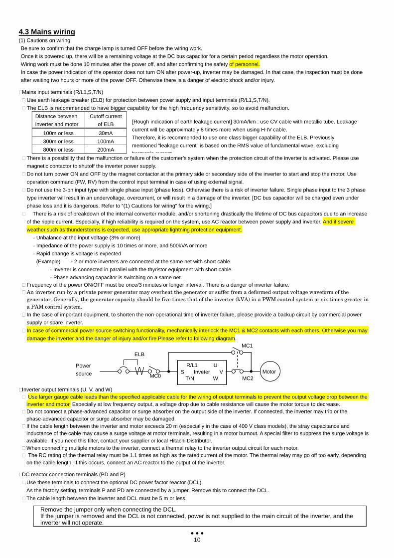
⑩ In case of commercial power source switching functionality, mechanically interlock the MC1 & MC2 contacts with each others. Otherwise you may
damage the inverter and the danger of injury and/or fire.Please refer to following diagram.
⑩Inverter output terminals (U, V, and W) ⑩ Use larger gauge cable leads than the specified applicable cable for the wiring of output terminals to prevent the output voltage drop between the
inverter and motor. Especially at low frequency output, a voltage drop due to cable resistance will cause the motor torque to decrease. ⑩ Do not connect a phase-advanced capacitor or surge absorber on the output side of the inverter. If connected, the inverter may trip or the
phase-advanced capacitor or surge absorber may be damaged. ⑩ If the cable length between the inverter and motor exceeds 20 m (especially in the case of 400 V class models), the stray capacitance and
inductance of the cable may cause a surge voltage at motor terminals, resulting in a motor burnout. A special filter to suppress the surge voltage is available. If you need this filter, contact your supplier or local Hitachi Distributor.
⑩ When connecting multiple motors to the inverter, connect a thermal relay to the inverter output circuit for each motor. ⑩ The RC rating of the thermal relay must be 1.1 times as high as the rated current of the motor. The thermal relay may go off too early, depending
on the cable length. If this occurs, connect an AC reactor to the output of the inverter. ⑩DC reactor connection terminals (PD and P)
⑩ Use these terminals to connect the optional DC power factor reactor (DCL).
As the factory setting, terminals P and PD are connected by a jumper. Remove this to connect the DCL.
⑩ The cable length between the inverter and DCL must be 5 m or less.
Remove the jumper only when connecting the DCL. If the jumper is removed and the DCL is not connected, power is not supplied to the main circuit of the inverter, and the inverter will not operate.
[Rough indication of earth leakage current] 30mA/km : use CV cable with metallic tube. Leakage
current will be approximately 8 times more when using H-IV cable.
Therefore, it is recommended to use one class bigger capability of the ELB. Previously
mentioned “leakage current” is based on the RMS value of fundamental wave, excluding
harmonic current.
Power
source
R/L1 U S Inveter V
T/N W Motor
ELB
MC0
MC1
MC2
11
⑩Inverter ground terminal (G )
⑩ Be sure to ground the inverter and motor to prevent electric shock.
⑩ According to the Electric Apparatus Engineering Regulations, connect 200 V class models to grounding electrodes constructed in compliance with
type-D grounding (conventional type-III grounding with ground resistance of 100Ω or less) or the 400 V class models to grounding electrodes
constructed in compliance with type-C grounding (conventional special type-III grounding with ground resistance of 10Ω or less).
⑩ Use a grounding cable thicker than the specified applicable cable, and make the ground wiring as short as possible.
⑩ When grounding multiple inverters, avoid a multi-drop connection of the grounding route and formation of a ground loop, otherwise the inverter
may malfunction.
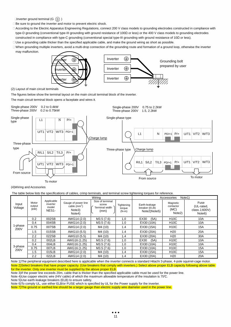
(2) Layout of main circuit terminals
The figures below show the terminal layout on the main circuit terminal block of the inverter.
The main circuit terminal block opens a faceplate and wires it. Single-phase 200V 0.2 to 0.4kW Three-phase 200V 0.2 to 0.75kW
(4)Wiring and Accesories
The table below lists the specifications of cables, crimp terminals, and terminal screw tightening torques for reference. Wiring Accessories Note1)
Input Voltage
Motor output (kW)
Applicable inverter model
NES1-
Gauge of power line cable (mm2)
Note3) Note4)
Size of terminal screw
Terminal width (mm)
Tightening torque (N-m)
Earth-leakage breaker (ELB)
Note2)Note5)
Magnetic contactor
(MC) Note2)
Fuse (UL-rated,
class J,600V) Note6)
0.2 002SB AWG14 (2.0) M3.5 (7.6) 1.0 EX30 (5A) H10C 10A 0.4 004SB AWG14 (2.0) M3.5 (7.6) 1.0 EX30 (10A) H10C 10A
0.75 007SB AWG14 (2.0) M4 (10) 1.4 EX30 (15A) H10C 15A
1.5 015SB AWG10 (5.5) M4 (10) 1.4 EX30 (20A) H20 20A
1-phase 200V
2.2 022SB AWG10 (5.5) M4 (10) 1.4 EX30 (20A) H20 30A 0.2 002LB AWG16 (1.25) M3.5 (7.6) 1.0 EX30 (5A) H10C 10A 0.4 004LB AWG16 (1.25) M3.5 (7.6) 1.0 EX30 (10A) H10C 10A
0.75 007LB AWG16 (1.25) M3.5 (7.6) 1.0 EX30 (10A) H10C 15A 1.5 015LB AWG14 (2.0) M4 (10) 1.4 EX30 (15A) H10C 15A
3-phase 200V
2.2 022LB AWG14 (2.0) M4 (10) 1.4 EX30 (20A) H20 20A
Note 1)The peripheral equipment described here is applicable when the inverter connects a standard Hitachi 3-phase, 4-pole squirrel-cage motor. Note 2)Select breakers that have proper capacity. (Use breakers that comply with inverters.) Select above proper ELB capacity following above table for the inverter. Only one inverter must be supplied by the above proper ELB. Note 3)If the power line exceeds 20m, cable that is thicker than the specified applicable cable must be used for the power line. Note 4)Use copper electric wire (HIV cable) of which the maximum allowable temperature of the insulation is 75°C. Note 5)Use earth-leakage breakers (ELB) to ensure safety. Note 6)To comply UL, use either ELB/or FUSE which is specified by UL for the Power supply for the inverter. Note 7)The ground or earthed line should be a larger gauge than electric supply wire diameter used in the power line.
Three-phase type
Single-phase type
Three-phase
type
From source
To motor
L1 N P/+
PD/+1 W/T3 V/T2 U/T1
R/L1 T/L3 P/+
PD/+1 W/T3 V/T2 U/T1
S/L2
Single-phase type
L1 N PD/+1 P/+ U/T1 W/T3 V/T2
R/L1 T/L3 S/L2 W/T3 V/T2 U/T1 PD/+1
P/+
From source To motor
Single-phase 200V 0.75 to 2.2kW Three-phase 200V 1.5, 2.2kW
Charge lump
Charge lump
Inverter
Inverter
Inverter Grounding bolt prepared by user
Inverter
Inverter
Inverter
12
5.1 Confirmation before power up the inverter Please confirm the followings before operation.
(1) Connection of the power input (R,S,T, L1,N) and motor (U/T1, V/T2, W/T3) is correctly connected. Otherwise there is a risk of inverter failure. (2) There must be no incorrect-connection of the control wiring. Otherwise there is a risk of inverter failure. (3) Earth grounding is properly connected. Otherwise there is a risk of electric shock. (4) There is no ground fault other than earth grounding terminal. Otherwise there is a risk of inverter failure. (5) There must be no short circuit such as wire strands or chips etc., there must be no tools left inside the inverter. Otherwise there is a risk of inverter failure.
(6) There must be no short circuit or ground fault at the output side. Otherwise there is a risk of inverter failure.
(7) Front cover must be closed. Otherwise there is a risk of inverter failure.
5.2 Changing parameters
One of the following is required when changing parameters on NE-S1 series inverters. (1) Dedicated operator (NES1-OP)
The operator (NES1-OP) is used with integration onto the inverter. It is not possible to use the operator external with cable. (2) Digital operator (OPE-SRmini,OPE-S/SR/SBK)
Digital operator can be used with connector cable (ICS-1,3) and connected to the RS422/RS485 port (RJ45) in the inverter. Turn the changeover switch to the operator side (OFF side) in that case (See page 9). Refer to the manual for each operator for the detailed information.
(3) 5-line LCD operator (WOP)
WOP having serial number of “16918938000081” or later (2011/07 production) is applied to NE-S1 series inverter. (English only) WOP can be used with connector cable (ICS-1,3) and connected to the RS422/RS485 port (RJ45) in the inverter. Turn the changeover switch to
the operator side (OFF side) in that case (See page 9). Refer to the manual for WOP for the detailed information. (4) PC programming tool (ProDriveNext)
ProDriveNext Version “1.2.33.000” and later is applied to the NE-S1 series inverter. PC can be used with connector cable (ICS-1,3) and connected to the RS422/RS485 port (RJ45) in the inverter. Turn the selection switch to the operator side (OFF side) in that case (See page 9). Refer to the manual for ProDriveNext for the detailed information.
NOTE: It is necessary to turn power off to store th e changed data.
5.3 Power up the inverter
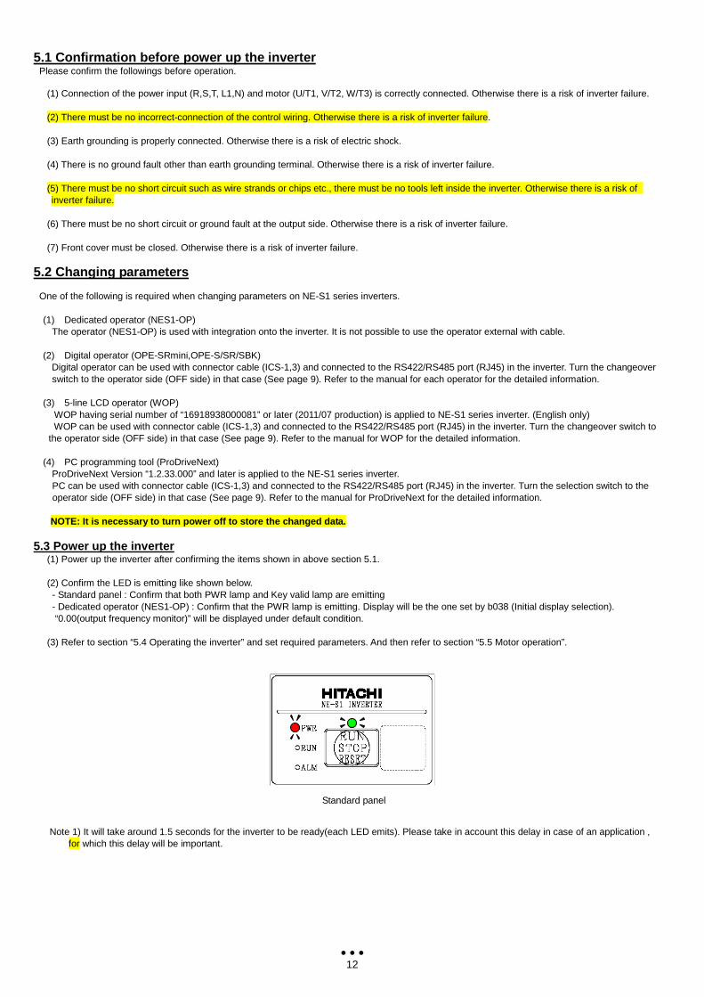
(1) Power up the inverter after confirming the items shown in above section 5.1. (2) Confirm the LED is emitting like shown below. - Standard panel : Confirm that both PWR lamp and Key valid lamp are emitting - Dedicated operator (NES1-OP) : Confirm that the PWR lamp is emitting. Display will be the one set by b038 (Initial display selection). “0.00(output frequency monitor)” will be displayed under default condition.
(3) Refer to section “5.4 Operating the inverter” and set required parameters. And then refer to section “5.5 Motor operation”. Note 1) It will take around 1.5 seconds for the inverter to be ready(each LED emits). Please take in account this delay in case of an application ,
for which this delay will be important.
Standard panel
13
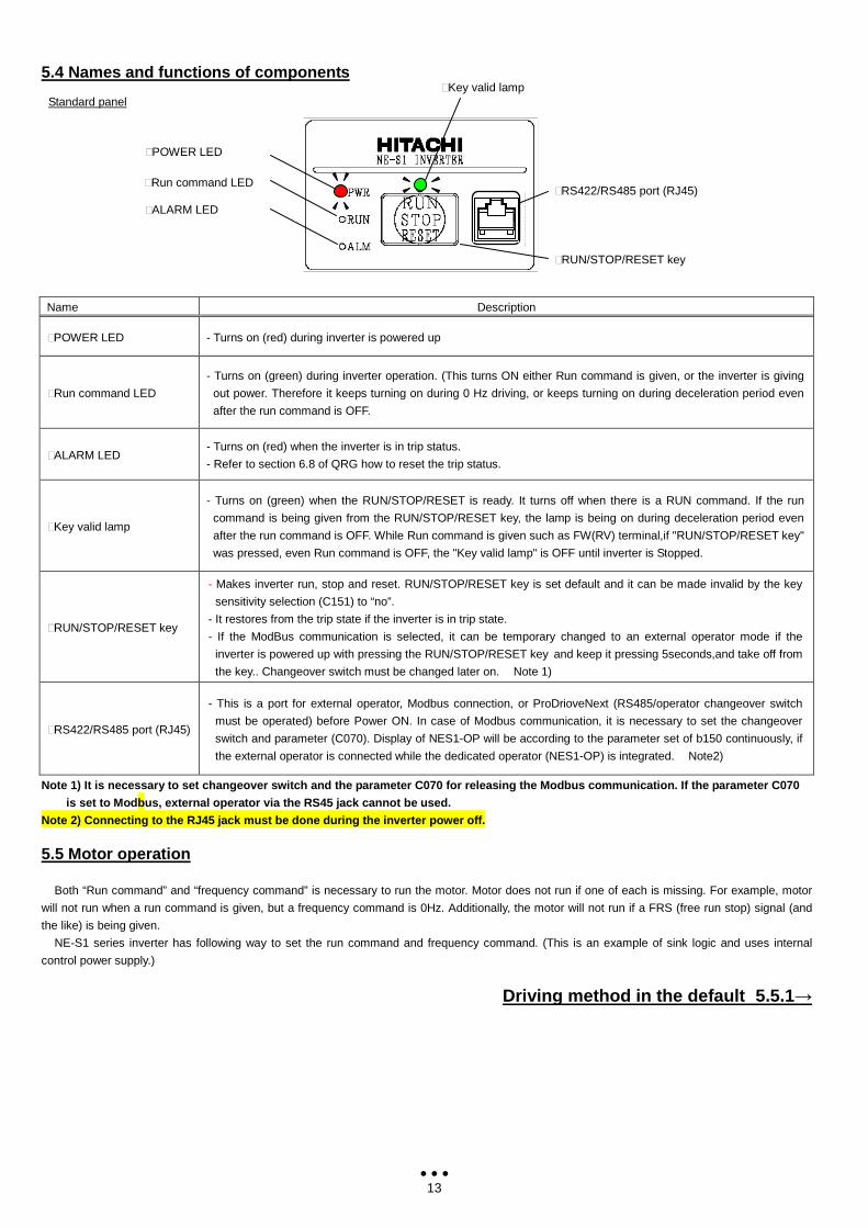
5.4 Names and functions of components Standard panel
Name Description
⑩POWER LED - Turns on (red) during inverter is powered up
⑩Run command LED
- Turns on (green) during inverter operation. (This turns ON either Run command is given, or the inverter is giving
out power. Therefore it keeps turning on during 0 Hz driving, or keeps turning on during deceleration period even
after the run command is OFF.
⑩ALARM LED - Turns on (red) when the inverter is in trip status.
- Refer to section 6.8 of QRG how to reset the trip status.
⑩Key valid lamp
- Turns on (green) when the RUN/STOP/RESET is ready. It turns off when there is a RUN command. If the run
command is being given from the RUN/STOP/RESET key, the lamp is being on during deceleration period even
after the run command is OFF. While Run command is given such as FW(RV) terminal,if "RUN/STOP/RESET key"
was pressed, even Run command is OFF, the "Key valid lamp" is OFF until inverter is Stopped.
⑩RUN/STOP/RESET key
- Makes inverter run, stop and reset. RUN/STOP/RESET key is set default and it can be made invalid by the key
sensitivity selection (C151) to “no”.
- It restores from the trip state if the inverter is in trip state.
- If the ModBus communication is selected, it can be temporary changed to an external operator mode if the
inverter is powered up with pressing the RUN/STOP/RESET key and keep it pressing 5seconds,and take off from
the key.. Changeover switch must be changed later on. Note 1)
⑩RS422/RS485 port (RJ45)
- This is a port for external operator, Modbus connection, or ProDrioveNext (RS485/operator changeover switch
must be operated) before Power ON. In case of Modbus communication, it is necessary to set the changeover
switch and parameter (C070). Display of NES1-OP will be according to the parameter set of b150 continuously, if
the external operator is connected while the dedicated operator (NES1-OP) is integrated. Note2)
Note 1) It is necessary to set changeover switch an d the parameter C070 for releasing the Modbus commu nication. If the parameter C070
is set to Modbus, external operator via the RS45 ja ck cannot be used.
Note 2) Connecting to the RJ45 jack must be done du ring the inverter power off.
5.5 Motor operation
Both “Run command” and “frequency command” is necessary to run the motor. Motor does not run if one of each is missing. For example, motor
will not run when a run command is given, but a frequency command is 0Hz. Additionally, the motor will not run if a FRS (free run stop) signal (and
the like) is being given.
NE-S1 series inverter has following way to set the run command and frequency command. (This is an example of sink logic and uses internal
control power supply.)
Driving method in the default 5.5.1→
⑩POWER LED
⑩ALARM LED
⑩Run command LED ⑩RS422/RS485 port (RJ45)
⑩Key valid lamp
⑩RUN/STOP/RESET key
14
5.5.1 Driving with the standard panel
RUN/STOP/RESET key on the standard operation panel is effective regardless of the setting of the driving order method(A002). Thus, the following
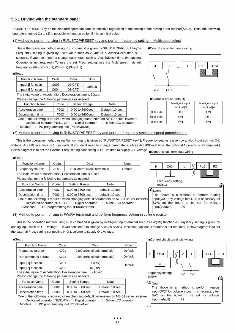
operation method (1) to (3) is possible without an option if it is an initial value. (1)Method to perform driving in RUN/STOP/RESET key and perform frequency setting in Multispeed select
This is the operation method using Run command is given by "RUN/STOP/RESET key" &
Frequency setting is given by Fixed value such as 20/40/60Hz, Accel&Decel time is 10
seconds. If you don't need to change parameters such as Accel&Decel time, the optional
Operator is not required.) To use the set Freq. setting, use the Multi-speed default
frequency setting (1=60Hz),(2=40Hz),(3=20Hz). Setup
Function Name Code Data Note
Input [3] function C003 02(CF1)
Input [4] function C004 03(CF2) Default
The initial value of Acceleration/ Deceleration time is 10sec.
Please change the following parameters as needed.
Function Name Code Setting Range Note
Acceleration time F002 0.00 to 3600sec. Default⑩10 sec.
Deceleration time F003 0.00 to 3600sec. Default⑩10 sec. One of the following is required when changing parameters on NE-S1 series inverters.
Dedicated operator (NES1-OP) ⑩ Digital operator ⑩ 5-line LCD operator ⑩ Modbus ⑩ PC programming tool (ProDriveNext)
(2) Method to perform driving in RUN/STOP/RESET key and perform frequency setting in speed potentiometer
This is the operation method using Run command is given by "RUN/STOP/RESET key" & Frequency setting is given by analog input such as O-L
voltage, Accel&Decel time is 10 seconds. If you don't need to change parameter such as Accel&Decel time, the optional Operator is not required.)
Below diagram is to set the external Freq. setting connecting H-O-L volume to supply O-L voltage. Setup
Function Name Code Data Note
Frequency source A001 01(Control circuit terminals) Default
The initial value of Acceleration/ Deceleration time is 10sec.
Please change the following parameters as needed. Function Name Code Setting Range Note
Acceleration time F002 0.00 to 3600 sec. default⑩10 sec.
Deceleration time F003 0.00 to 3600 sec. default⑩10 sec. One of the following is required when changing default parameters on NE-S1 series inverters.
Dedicated operator (NES1-OP) ⑩ Digital operator ⑩ 5-line LCD operator ⑩ Modbus ⑩ PC programming tool (ProDriveNext)
(3) Method to perform driving in FW/RV teraminal and perform frequency setting in volume resistor
This is the operation method using Run command is given by intelligent input terminal such as FW(RV) function & Frequency setting is given by
analog input such as O-L voltage. If you don't need to change such as Accel&Decel time, optional Operator is not required.) Below diagram is to set
the external Freq. setting connecting H-O-L volume to supply O-L voltage.
Setup Function Name Code Data Note
Frequency source A001 01(Control circuit terminals) Default
Run command source A002 01(Control circuit terminals) Default
Input [1] function C001 00(FW)
Input [2] function C002 01(RV) Default
The initial value of Acceleration/ Deceleration time is 10sec. Please change the following parameters as needed.
Function Name Code Setting Range Note
Acceleration time F002 0.00 to 3600 sec. Default⑩10 sec.
Deceleration time F003 0.00 to 3600 sec. Default⑩10 sec. One of the following is required when changing default parameters on NE-S1 series inverters.
Dedicated operator (NES1-OP) ⑩ Digital operator ⑩ 5-line LCD operator ⑩ Modbus ⑩ PC programming tool (ProDriveNext)
Example of use(default) Intelligent input
terminal [3] Intelligent input
terminal [4]
60Hz order OFF ON
40Hz order ON OFF
20Hz order ON ON
Control circuit terminals wiring
P24 PLC L 3
CF1 CF2
4 …
Note) The above is a method to perform analog input(O/OI) by voltage input. It is necessary for SW6 on the board to be set for voltage input(default). →P9
Control circuit terminals wiring
P24 PLC L 1 2 L O/OI H
FW RV Frequency setting resistor
P24 PLC L O/OI H
Frequency setting resistor
Note) The above is a method to perform analog input(O/OI) by voltage input. It is necessary for SW6 on the board to be set for voltage input(default). →P9
Control circuit terminals wiring
15
6.1 Specifications
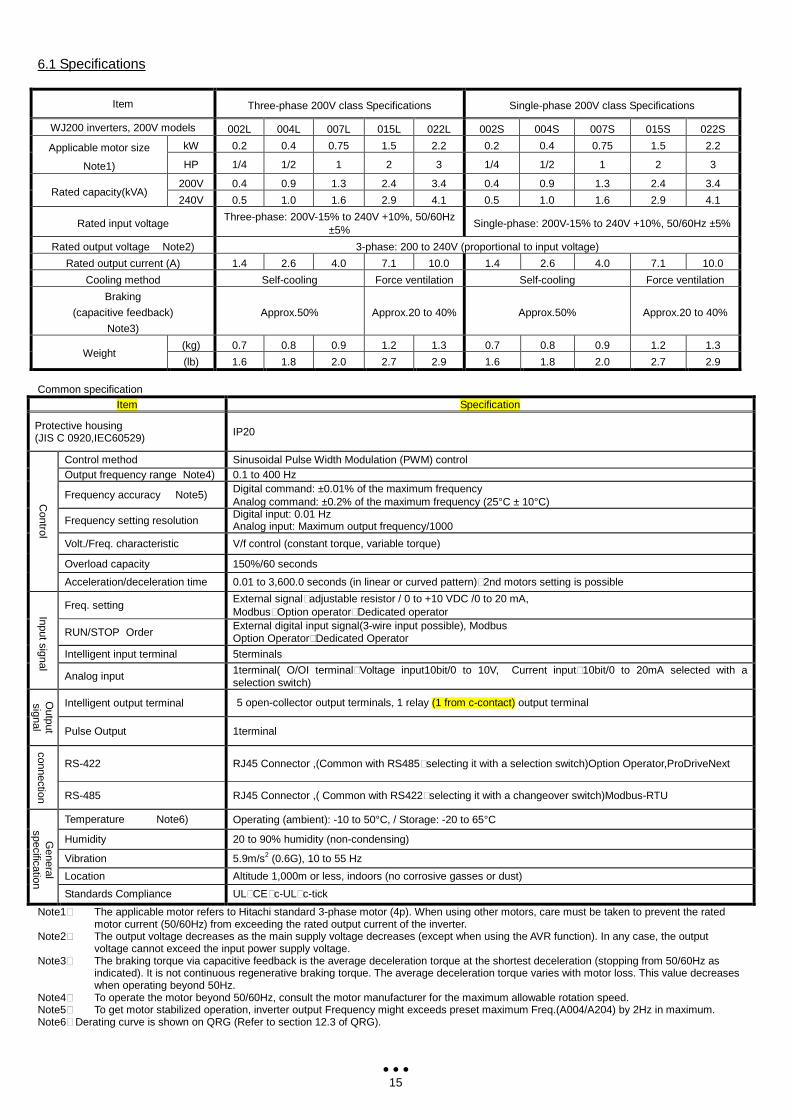
Item Three-phase 200V class Specifications Single-phase 200V class Specifications
WJ200 inverters, 200V models 002L 004L 007L 015L 022L 002S 004S 007S 015S 022S
kW 0.2 0.4 0.75 1.5 2.2 0.2 0.4 0.75 1.5 2.2 Applicable motor size
Note1) HP 1/4 1/2 1 2 3 1/4 1/2 1 2 3
200V 0.4 0.9 1.3 2.4 3.4 0.4 0.9 1.3 2.4 3.4 Rated capacity(kVA)
240V 0.5 1.0 1.6 2.9 4.1 0.5 1.0 1.6 2.9 4.1
Rated input voltage Three-phase: 200V-15% to 240V +10%, 50/60Hz
±5% Single-phase: 200V-15% to 240V +10%, 50/60Hz ±5%
Rated output voltage Note2) 3-phase: 200 to 240V (proportional to input voltage)
Rated output current (A) 1.4 2.6 4.0 7.1 10.0 1.4 2.6 4.0 7.1 10.0
Cooling method Self-cooling Force ventilation Self-cooling Force ventilation
Braking
(capacitive feedback)
Note3)
Approx.50% Approx.20 to 40% Approx.50% Approx.20 to 40%
(kg) 0.7 0.8 0.9 1.2 1.3 0.7 0.8 0.9 1.2 1.3 Weight
(lb) 1.6 1.8 2.0 2.7 2.9 1.6 1.8 2.0 2.7 2.9 Common specification
Item Specification
Protective housing (JIS C 0920,IEC60529)
IP20
Control method Sinusoidal Pulse Width Modulation (PWM) control Output frequency range Note4) 0.1 to 400 Hz
Frequency accuracy Note5) Digital command: ±0.01% of the maximum frequency Analog command: ±0.2% of the maximum frequency (25°C ± 10°C)
Frequency setting resolution Digital input: 0.01 Hz Analog input: Maximum output frequency/1000
Volt./Freq. characteristic V/f control (constant torque, variable torque)
Overload capacity 150%/60 seconds
Control
Acceleration/deceleration time 0.01 to 3,600.0 seconds (in linear or curved pattern)⑩2nd motors setting is possible
Freq. setting External signal⑩adjustable resistor / 0 to +10 VDC /0 to 20 mA, Modbus⑩Option operator⑩Dedicated operator
RUN/STOP Order External digital input signal(3-wire input possible), Modbus Option Operator⑩Dedicated Operator
Intelligent input terminal 5terminals
Input signal
Analog input 1terminal( O/OI terminal⑩Voltage input10bit/0 to 10V, Current input⑩10bit/0 to 20mA selected with a selection switch)
Intelligent output terminal 5 open-collector output terminals, 1 relay (1 from c-contact) output terminal Output
signal Pulse Output 1terminal
RS-422 RJ45 Connector ,(Common with RS485⑩selecting it with a selection switch)Option Operator,ProDriveNext connection RS-485 RJ45 Connector ,( Common with RS422⑩selecting it with a changeover switch)Modbus-RTU
Temperature Note6) Operating (ambient): -10 to 50°C, / Storage: -20 to 65°C
Humidity 20 to 90% humidity (non-condensing)
Vibration 5.9m/s2 (0.6G), 10 to 55 Hz
Location Altitude 1,000m or less, indoors (no corrosive gasses or dust)
General
specification
Standards Compliance UL⑩CE⑩c-UL⑩c-tick
Note1⑩ The applicable motor refers to Hitachi standard 3-phase motor (4p). When using other motors, care must be taken to prevent the rated motor current (50/60Hz) from exceeding the rated output current of the inverter.
Note2⑩ The output voltage decreases as the main supply voltage decreases (except when using the AVR function). In any case, the output voltage cannot exceed the input power supply voltage.
Note3⑩ The braking torque via capacitive feedback is the average deceleration torque at the shortest deceleration (stopping from 50/60Hz as indicated). It is not continuous regenerative braking torque. The average deceleration torque varies with motor loss. This value decreases when operating beyond 50Hz.
Note4⑩ To operate the motor beyond 50/60Hz, consult the motor manufacturer for the maximum allowable rotation speed. Note5⑩ To get motor stabilized operation, inverter output Frequency might exceeds preset maximum Freq.(A004/A204) by 2Hz in maximum. Note6⑩ Derating curve is shown on QRG (Refer to section 12.3 of QRG).
16
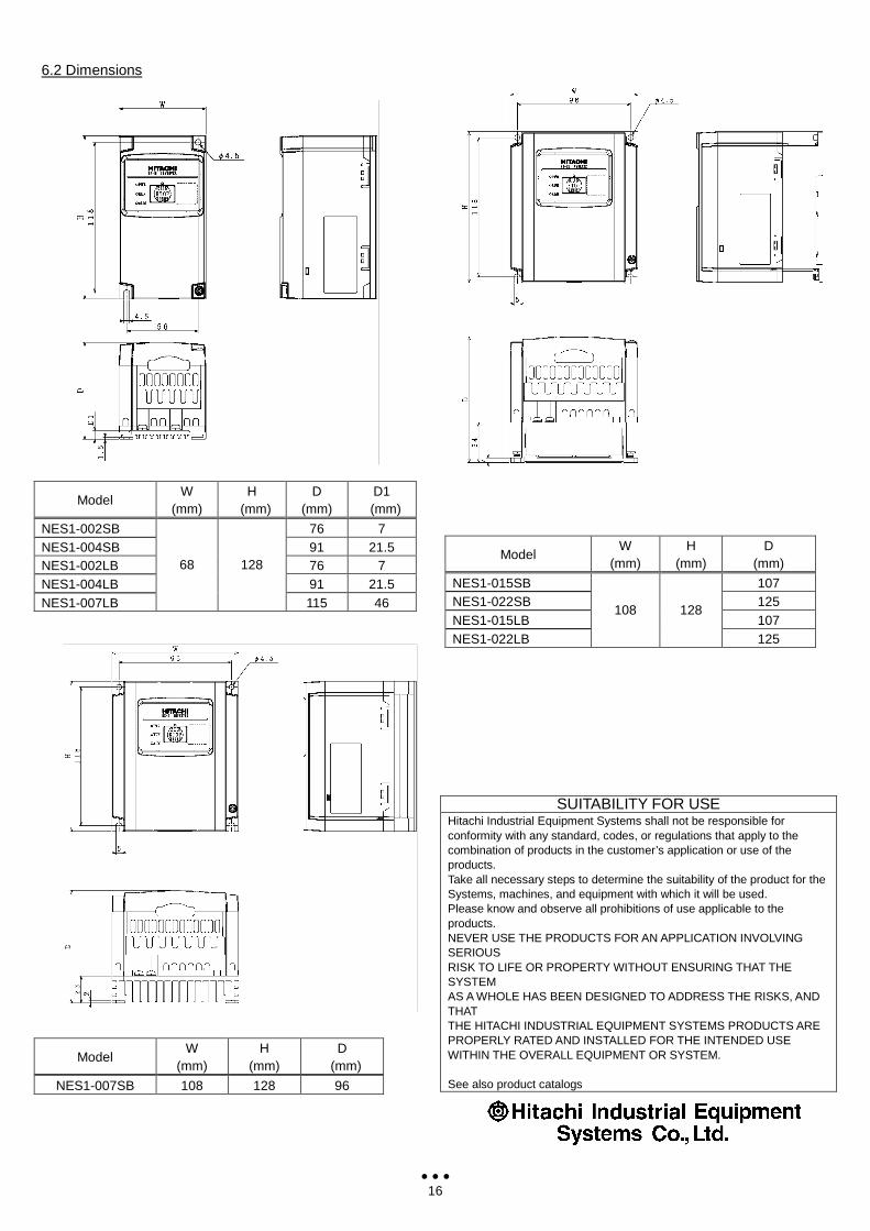
6.2 Dimensions
SUITABILITY FOR USE Hitachi Industrial Equipment Systems shall not be responsible for conformity with any standard, codes, or regulations that apply to the combination of products in the customer’s application or use of the products. Take all necessary steps to determine the suitability of the product for the Systems, machines, and equipment with which it will be used. Please know and observe all prohibitions of use applicable to the products. NEVER USE THE PRODUCTS FOR AN APPLICATION INVOLVING SERIOUS RISK TO LIFE OR PROPERTY WITHOUT ENSURING THAT THE SYSTEM AS A WHOLE HAS BEEN DESIGNED TO ADDRESS THE RISKS, AND THAT THE HITACHI INDUSTRIAL EQUIPMENT SYSTEMS PRODUCTS ARE PROPERLY RATED AND INSTALLED FOR THE INTENDED USE WITHIN THE OVERALL EQUIPMENT OR SYSTEM. See also product catalogs
Model W
(mm) H
(mm) D
(mm) D1
(mm)
NES1-002SB 76 7 NES1-004SB 91 21.5 NES1-002LB 76 7 NES1-004LB 91 21.5 NES1-007LB
68 128
115 46
Model W
(mm) H
(mm) D
(mm)
NES1-007SB 108 128 96
Model W
(mm) H
(mm) D
(mm)
NES1-015SB 107 NES1-022SB 125 NES1-015LB 107 NES1-022LB
108 128
125
17
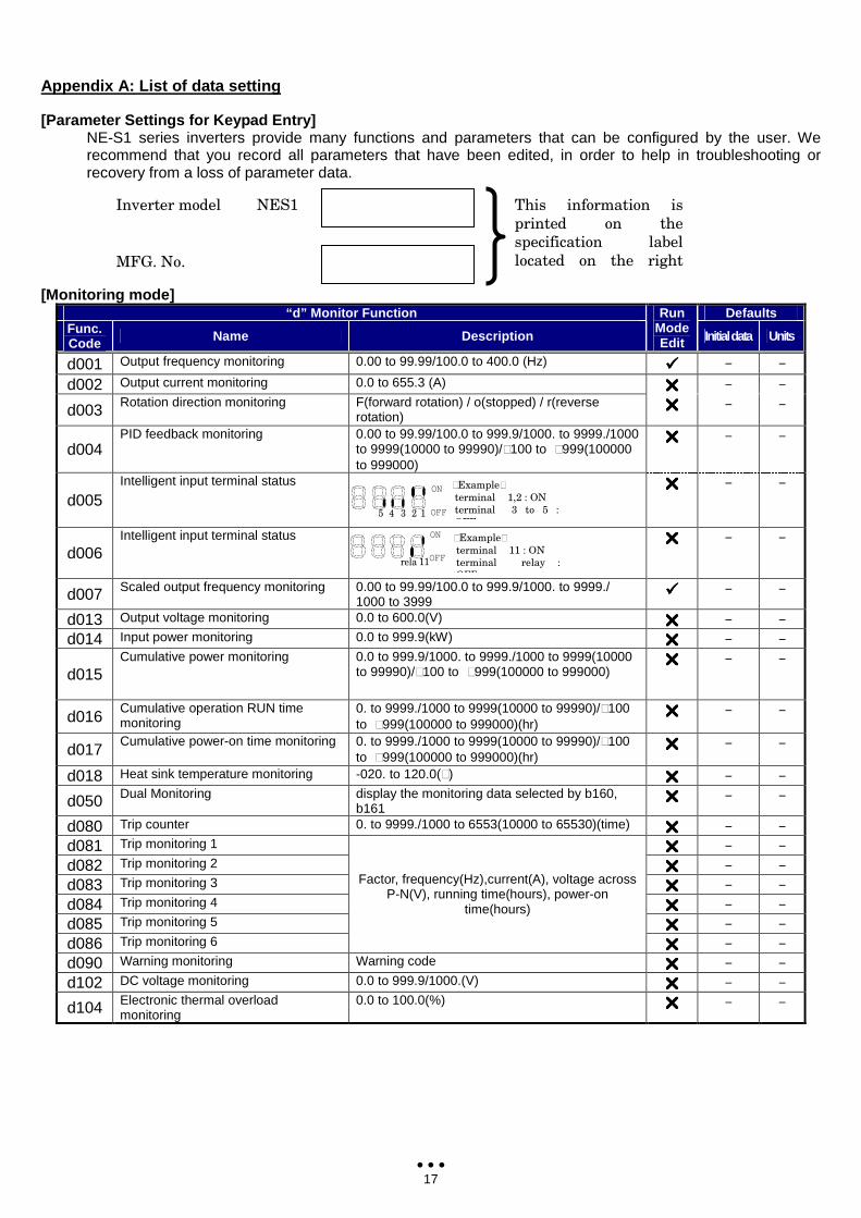
Appendix A: List of data setting
[Parameter Settings for Keypad Entry] NE-S1 series inverters provide many functions and parameters that can be configured by the user. We recommend that you record all parameters that have been edited, in order to help in troubleshooting or recovery from a loss of parameter data.
[Monitoring mode] “d” Monitor Function Defaults
Func. Code Name Description
Run Mode Edit Initial data Units
d001 Output frequency monitoring 0.00 to 99.99/100.0 to 400.0 (Hz) − −
d002 Output current monitoring 0.0 to 655.3 (A) − −
d003 Rotation direction monitoring F(forward rotation) / o(stopped) / r(reverse rotation)
− −
d004 PID feedback monitoring 0.00 to 99.99/100.0 to 999.9/1000. to 9999./1000
to 9999(10000 to 99990)/⑩100 to ⑩999(100000 to 999000)
− −
d005 Intelligent input terminal status − −
d006 Intelligent input terminal status − −
d007 Scaled output frequency monitoring 0.00 to 99.99/100.0 to 999.9/1000. to 9999./ 1000 to 3999
− −
d013 Output voltage monitoring 0.0 to 600.0(V) − −
d014 Input power monitoring 0.0 to 999.9(kW) − −
d015 Cumulative power monitoring 0.0 to 999.9/1000. to 9999./1000 to 9999(10000
to 99990)/⑩100 to ⑩999(100000 to 999000) − −
d016 Cumulative operation RUN time monitoring
0. to 9999./1000 to 9999(10000 to 99990)/⑩100 to ⑩999(100000 to 999000)(hr)
− −
d017 Cumulative power-on time monitoring 0. to 9999./1000 to 9999(10000 to 99990)/⑩100
to ⑩999(100000 to 999000)(hr) − −
d018 Heat sink temperature monitoring -020. to 120.0(⑩) − −
d050 Dual Monitoring display the monitoring data selected by b160, b161
− −
d080 Trip counter 0. to 9999./1000 to 6553(10000 to 65530)(time) − −
d081 Trip monitoring 1 − −
d082 Trip monitoring 2 − −
d083 Trip monitoring 3 − −
d084 Trip monitoring 4 − −
d085 Trip monitoring 5 − −
d086 Trip monitoring 6
Factor, frequency(Hz),current(A), voltage across P-N(V), running time(hours), power-on
time(hours)
− −
d090 Warning monitoring Warning code − −
d102 DC voltage monitoring 0.0 to 999.9/1000.(V) − −
d104 Electronic thermal overload monitoring
0.0 to 100.0(%) − −
Inverter model NES1
MFG. No.
This information is
printed on the
specification label
located on the right
side of the inverter
⑩Example⑩
terminal 1,2 : ON
terminal 3 to 5 :
OFF
ON
OFF 1 2 3 4 5
ON
OFF
⑩Example⑩
terminal 11 : ON
terminal relay :
OFF
11 rela
y
18
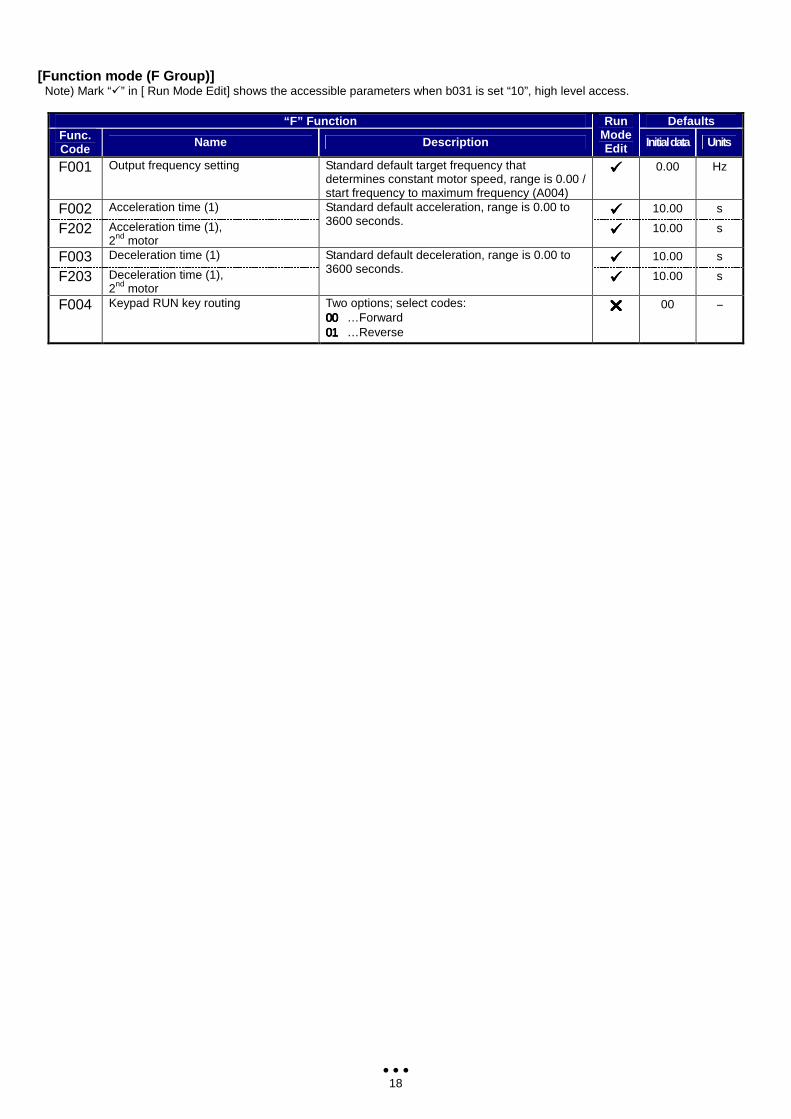
[Function mode (F Group)] Note) Mark “” in [ Run Mode Edit] shows the accessible parameters when b031 is set “10”, high level access.
“F” Function Defaults Func. Code Name Description
Run Mode Edit Initial data Units
F001 Output frequency setting Standard default target frequency that determines constant motor speed, range is 0.00 / start frequency to maximum frequency (A004)
0.00 Hz
F002 Acceleration time (1) 10.00 s
F202 Acceleration time (1), 2nd motor
Standard default acceleration, range is 0.00 to 3600 seconds.
10.00 s
F003 Deceleration time (1) 10.00 s
F203 Deceleration time (1), 2nd motor
Standard default deceleration, range is 0.00 to 3600 seconds.
10.00 s
F004 Keypad RUN key routing Two options; select codes: 00000000 …Forward 01010101 …Reverse
00 −
19
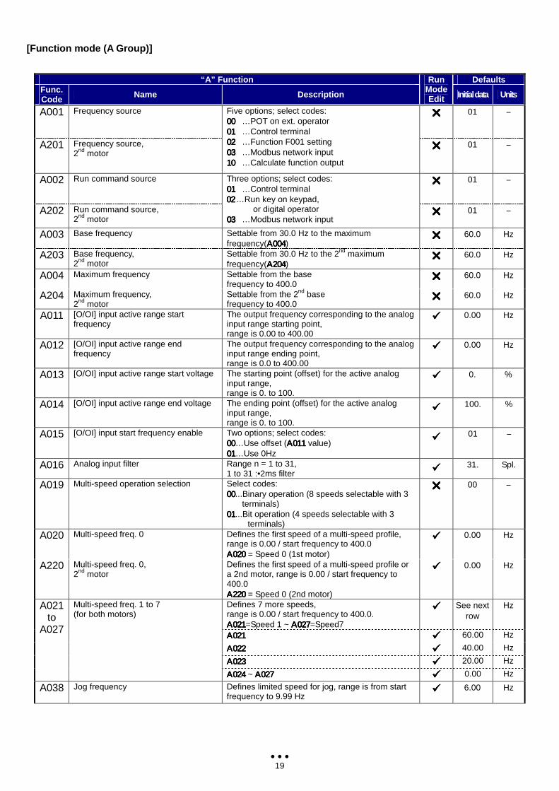
[Function mode (A Group)]
“A” Function Defaults Func. Code Name Description
Run Mode Edit Initial data Units
A001 Frequency source 01 −
A201 Frequency source, 2nd motor
Five options; select codes: 00000000 …POT on ext. operator 01010101 …Control terminal 02020202 …Function F001 setting 03030303 …Modbus network input 10101010 …Calculate function output
01 −
A002 Run command source 01 −
A202 Run command source, 2nd motor
Three options; select codes: 01010101 …Control terminal 02020202 …Run key on keypad,
or digital operator 03030303 …Modbus network input
01 −
A003 Base frequency Settable from 30.0 Hz to the maximum frequency(Α004Α004Α004Α004)
60.0 Hz
A203 Base frequency, 2nd motor
Settable from 30.0 Hz to the 2nd maximum frequency(Α204Α204Α204Α204)
60.0 Hz
A004 Maximum frequency Settable from the base frequency to 400.0
60.0 Hz
A204 Maximum frequency, 2nd motor
Settable from the 2nd base frequency to 400.0
60.0 Hz
A011 [O/OI] input active range start frequency
The output frequency corresponding to the analog input range starting point, range is 0.00 to 400.00
0.00 Hz
A012 [O/OI] input active range end frequency
The output frequency corresponding to the analog input range ending point, range is 0.0 to 400.00
0.00 Hz
A013 [O/OI] input active range start voltage The starting point (offset) for the active analog input range, range is 0. to 100.
0. %
A014 [O/OI] input active range end voltage The ending point (offset) for the active analog input range, range is 0. to 100.
100. %
A015 [O/OI] input start frequency enable Two options; select codes: 00000000…Use offset (Α011Α011Α011Α011 value) 01010101…Use 0Hz
01 −
A016 Analog input filter Range n = 1 to 31, 1 to 31 :•2ms filter 31. Spl.
A019 Multi-speed operation selection Select codes: 00000000...Binary operation (8 speeds selectable with 3
terminals) 01010101...Bit operation (4 speeds selectable with 3
terminals)
00 −
A020 Multi-speed freq. 0 Defines the first speed of a multi-speed profile, range is 0.00 / start frequency to 400.0 Α020Α020Α020Α020 = Speed 0 (1st motor)
0.00 Hz
A220 Multi-speed freq. 0, 2nd motor
Defines the first speed of a multi-speed profile or a 2nd motor, range is 0.00 / start frequency to 400.0 Α220Α220Α220Α220 = Speed 0 (2nd motor)
0.00 Hz
Defines 7 more speeds, range is 0.00 / start frequency to 400.0. Α021Α021Α021Α021=Speed 1 ~ Α027Α027Α027Α027=Speed7
See next row
Hz
Α021Α021Α021Α021 60.00 Hz
Α022Α022Α022Α022 40.00 Hz
Α023Α023Α023Α023 20.00 Hz
A021 to
A027
Multi-speed freq. 1 to 7 (for both motors)
Α024 Α024 Α024 Α024 ~ Α027Α027Α027Α027 0.00 Hz
A038 Jog frequency Defines limited speed for jog, range is from start frequency to 9.99 Hz
6.00 Hz
20
“A” Function Defaults Func. Code Name Description
Run Mode Edit Initial data Units
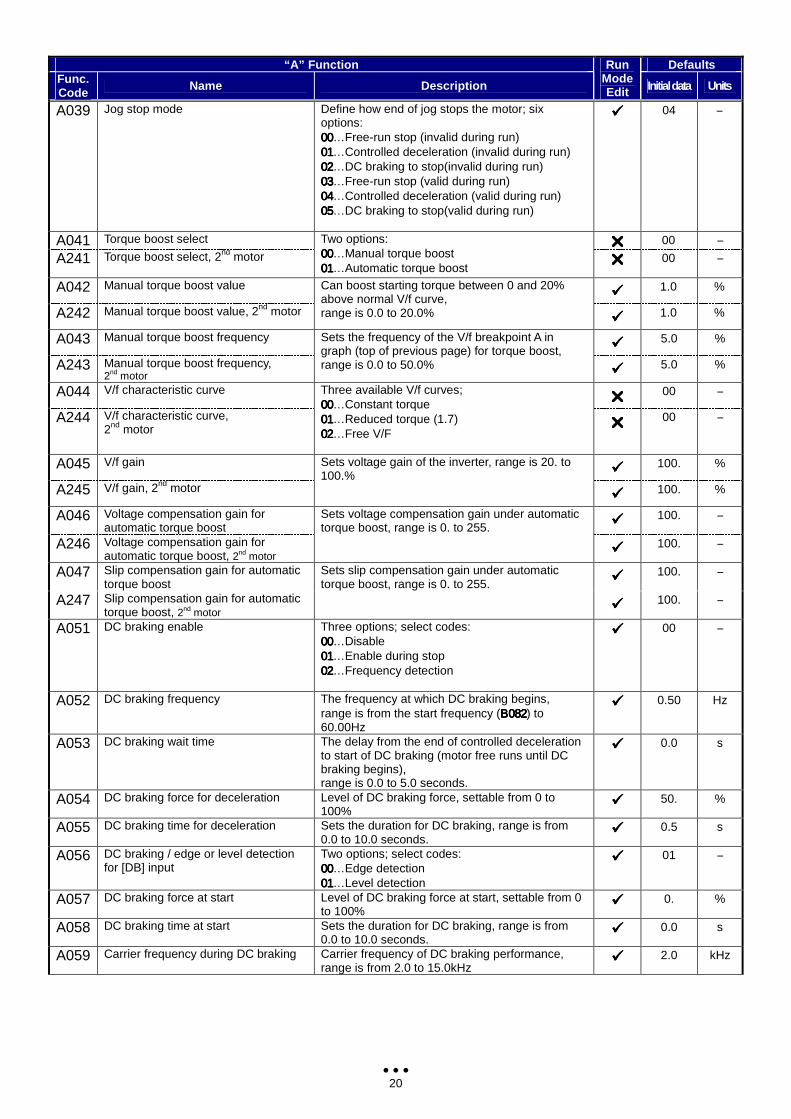
A039 Jog stop mode Define how end of jog stops the motor; six options: 00000000…Free-run stop (invalid during run) 01010101…Controlled deceleration (invalid during run) 02020202…DC braking to stop(invalid during run) 03030303…Free-run stop (valid during run) 04040404…Controlled deceleration (valid during run) 05050505…DC braking to stop(valid during run)
04 −
A041 Torque boost select 00 −
A241 Torque boost select, 2nd motor
Two options: 00000000…Manual torque boost 01010101…Automatic torque boost
00 −
A042 Manual torque boost value 1.0 %
A242 Manual torque boost value, 2nd motor
Can boost starting torque between 0 and 20% above normal V/f curve, range is 0.0 to 20.0% 1.0 %
A043 Manual torque boost frequency 5.0 %
A243 Manual torque boost frequency, 2nd motor
Sets the frequency of the V/f breakpoint A in graph (top of previous page) for torque boost, range is 0.0 to 50.0% 5.0 %
A044 V/f characteristic curve 00 −
A244 V/f characteristic curve, 2nd motor
Three available V/f curves; 00000000…Constant torque 01010101…Reduced torque (1.7) 02020202…Free V/F
00 −
A045 V/f gain 100. %
A245 V/f gain, 2nd motor
Sets voltage gain of the inverter, range is 20. to 100.%
100. %
A046 Voltage compensation gain for automatic torque boost 100. −
A246 Voltage compensation gain for automatic torque boost, 2nd motor
Sets voltage compensation gain under automatic torque boost, range is 0. to 255.
100. −
A047 Slip compensation gain for automatic torque boost 100. −
A247 Slip compensation gain for automatic torque boost, 2nd motor
Sets slip compensation gain under automatic torque boost, range is 0. to 255.
100. −
A051 DC braking enable Three options; select codes: 00000000…Disable 01010101…Enable during stop 02020202…Frequency detection
00 −
A052 DC braking frequency The frequency at which DC braking begins, range is from the start frequency (Β082Β082Β082Β082) to 60.00Hz
0.50 Hz
A053 DC braking wait time The delay from the end of controlled deceleration to start of DC braking (motor free runs until DC braking begins), range is 0.0 to 5.0 seconds.
0.0 s
A054 DC braking force for deceleration Level of DC braking force, settable from 0 to 100%
50. %
A055 DC braking time for deceleration Sets the duration for DC braking, range is from 0.0 to 10.0 seconds.
0.5 s
A056 DC braking / edge or level detection for [DB] input
Two options; select codes: 00000000…Edge detection 01010101…Level detection
01 −
A057 DC braking force at start Level of DC braking force at start, settable from 0 to 100%
0. %
A058 DC braking time at start Sets the duration for DC braking, range is from 0.0 to 10.0 seconds.
0.0 s
A059 Carrier frequency during DC braking Carrier frequency of DC braking performance, range is from 2.0 to 15.0kHz
2.0 kHz
21
“A” Function Defaults Func. Code Name Description
Run Mode Edit Initial data Units
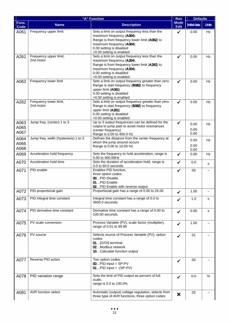
A061 Frequency upper limit Sets a limit on output frequency less than the maximum frequency (Α004Α004Α004Α004). Range is from frequency lower limit (Α062Α062Α062Α062) to maximum frequency (Α004Α004Α004Α004). 0.00 setting is disabled >0.00 setting is enabled
0.00 Hz
A261 Frequency upper limit, 2nd motor
Sets a limit on output frequency less than the maximum frequency (Α204Α204Α204Α204). Range is from frequency lower limit (Α262Α262Α262Α262) to maximum frequency (Α204Α204Α204Α204). 0.00 setting is disabled >0.00 setting is enabled
0.00 Hz
A062 Frequency lower limit Sets a limit on output frequency greater than zero. Range is start frequency (Β082Β082Β082Β082) to frequency upper limit (Α061Α061Α061Α061) 0.00 setting is disabled >0.00 setting is enabled
0.00 Hz
A262 Frequency lower limit, 2nd motor
Sets a limit on output frequency greater than zero. Range is start frequency (Β082Β082Β082Β082) to frequency upper limit (Α261Α261Α261Α261) 0.00 setting is disabled >0.00 setting is enabled
0.00 Hz
A063 A065 A067
Jump freq. (center) 1 to 3 Up to 3 output frequencies can be defined for the output to jump past to avoid motor resonances (center frequency) Range is 0.00 to 400.0 Hz
0.00
0.00 0.00
Hz
A064 A066 A068
Jump freq. width (hysteresis) 1 to 3 Defines the distance from the center frequency at which the jump around occurs Range is 0.00 to 10.00 Hz
0.50
0.50 0.50
Hz
A069 Acceleration hold frequency Sets the frequency to hold acceleration, range is 0.00 to 400.00Hz
0.00 Hz
A070 Acceleration hold time Sets the duration of acceleration hold, range is 0.0 to 60.0 seconds.
0.0 s
A071 PID enable Enables PID function, three option codes: 00000000…PID Disable 01010101…PID Enable 02020202…PID Enable with reverse output
00 −
A072 PID proportional gain Proportional gain has a range of 0.00 to 25.00 1.00 −
A073 PID integral time constant Integral time constant has a range of 0.0 to 3600.0 seconds.
1.0 s
A074 PID derivative time constant Derivative time constant has a range of 0.00 to 100.00 seconds.
0.00 s
A075 PV scale conversion Process Variable (PV), scale factor (multiplier), range of 0.01 to 99.99
1.00 −
A076 PV source Selects source of Process Variable (PV), option codes: 01010101…[O/OI] terminal 02020202…Modbus network 10101010…Calculate function output
01 −
A077 Reverse PID action Two option codes: 00000000…PID input = SP-PV 01010101…PID input = -(SP-PV)
00 −
A078 PID variation range Sets the limit of PID output as percent of full scale, range is 0.0 to 100.0%
0.0 %
A081 AVR function select Automatic (output) voltage regulation, selects from three type of AVR functions, three option codes: 02 −
22
“A” Function Defaults Func. Code Name Description
Run Mode Edit Initial data Units
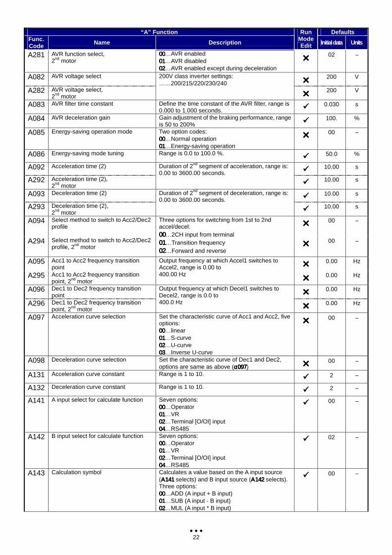
A281 AVR function select, 2nd motor
00000000…AVR enabled 01010101…AVR disabled 02020202…AVR enabled except during deceleration
02 −
A082 AVR voltage select 200 V
A282 AVR voltage select, 2nd motor
200V class inverter settings: ……200/215/220/230/240
200 V
A083 AVR filter time constant Define the time constant of the AVR filter, range is 0.000 to 1.000 seconds. 0.030 s
A084 AVR deceleration gain Gain adjustment of the braking performance, range is 50 to 200% 100. %
A085 Energy-saving operation mode Two option codes: 00000000…Normal operation 01010101…Energy-saving operation
00 −
A086 Energy-saving mode tuning Range is 0.0 to 100.0 %. 50.0 %
A092 Acceleration time (2) 10.00 s
A292 Acceleration time (2), 2nd motor
Duration of 2nd segment of acceleration, range is: 0.00 to 3600.00 seconds.
10.00 s
A093 Deceleration time (2) 10.00 s
A293 Deceleration time (2), 2nd motor
Duration of 2nd segment of deceleration, range is: 0.00 to 3600.00 seconds.
10.00 s
A094 Select method to switch to Acc2/Dec2 profile 00 −
A294 Select method to switch to Acc2/Dec2 profile, 2nd motor
Three options for switching from 1st to 2nd accel/decel: 00000000…2CH input from terminal 01010101…Transition frequency 02020202…Forward and reverse
00 −
A095 Acc1 to Acc2 frequency transition point 0.00 Hz
A295 Acc1 to Acc2 frequency transition point, 2nd motor
Output frequency at which Accel1 switches to Accel2, range is 0.00 to 400.00 Hz
0.00 Hz
A096 Dec1 to Dec2 frequency transition point 0.00 Hz
A296 Dec1 to Dec2 frequency transition point, 2nd motor
Output frequency at which Decel1 switches to Decel2, range is 0.0 to 400.0 Hz
0.00 Hz
A097 Acceleration curve selection Set the characteristic curve of Acc1 and Acc2, five options: 00000000…linear 01010101…S-curve 02020202…U-curve 03030303…Inverse U-curve
00 −
A098 Deceleration curve selection Set the characteristic curve of Dec1 and Dec2, options are same as above (α097α097α097α097) 00 −
A131 Acceleration curve constant Range is 1 to 10. 2 −
A132 Deceleration curve constant Range is 1 to 10. 2 −
A141 A input select for calculate function Seven options: 00000000…Operator 01010101…VR 02020202…Terminal [O/OI] input 04040404…RS485
00 −
A142 B input select for calculate function Seven options: 00000000…Operator 01010101…VR 02020202…Terminal [O/OI] input 04040404…RS485
02 −
A143 Calculation symbol Calculates a value based on the A input source (Α141Α141Α141Α141 selects) and B input source (Α142Α142Α142Α142 selects). Three options: 00000000…ADD (A input + B input) 01010101…SUB (A input - B input) 02020202…MUL (A input * B input)
00 −
23
“A” Function Defaults Func. Code Name Description
Run Mode Edit Initial data Units
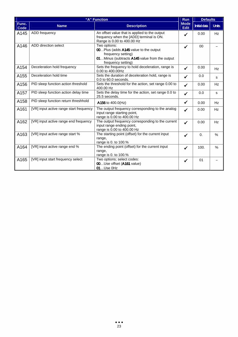
A145 ADD frequency An offset value that is applied to the output frequency when the [ADD] terminal is ON. Range is 0.00 to 400.00 Hz
0.00 Hz
A146 ADD direction select Two options: 00000000…Plus (adds Α145Α145Α145Α145 value to the output
frequency setting) 01010101…Minus (subtracts Α145Α145Α145Α145 value from the output
frequency setting)
00 −
A154 Deceleration hold frequency Sets the frequency to hold deceleration, range is 0.00 to 400.00Hz 0.00 Hz
A155 Deceleration hold time Sets the duration of deceleration hold, range is 0.0 to 60.0 seconds. 0.0 s
A156 PID sleep function action threshold Sets the threshold for the action, set range 0.00 to 400.00 Hz 0.00 Hz
A157 PID sleep function action delay time Sets the delay time for the action, set range 0.0 to 25.5 seconds. 0.0 s
A158 PID sleep function return threshhold Α156Α156Α156Α156 to 400.0(Hz) 0.00 Hz
A161 [VR] input active range start frequency The output frequency corresponding to the analog input range starting point, range is 0.00 to 400.00 Hz
0.00 Hz
A162 [VR] input active range end frequency The output frequency corresponding to the current input range ending point, range is 0.00 to 400.00 Hz
0.00 Hz
A163 [VR] input active range start % The starting point (offset) for the current input range, range is 0. to 100.%
0. %
A164 [VR] input active range end % The ending point (offset) for the current input range, range is 0. to 100.%
100. %
A165 [VR] input start frequency select Two options; select codes: 00000000…Use offset (Α161Α161Α161Α161 value) 01010101…Use 0Hz
01 −
24
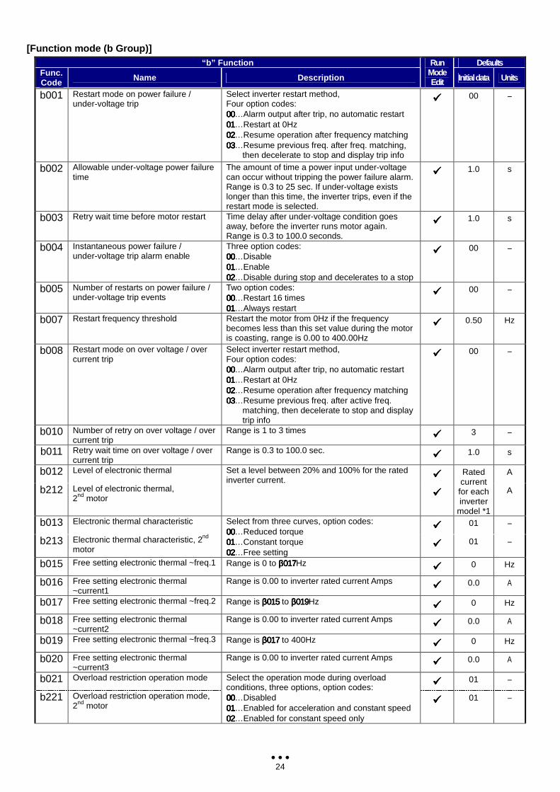
[Function mode (b Group)] “b” Function Defaults
Func. Code Name Description
Run Mode Edit Initial data Units
b001 Restart mode on power failure / under-voltage trip
Select inverter restart method, Four option codes: 00000000…Alarm output after trip, no automatic restart 01010101…Restart at 0Hz 02020202…Resume operation after frequency matching 03030303…Resume previous freq. after freq. matching,
then decelerate to stop and display trip info
00 −
b002 Allowable under-voltage power failure time
The amount of time a power input under-voltage can occur without tripping the power failure alarm. Range is 0.3 to 25 sec. If under-voltage exists longer than this time, the inverter trips, even if the restart mode is selected.
1.0 s
b003 Retry wait time before motor restart Time delay after under-voltage condition goes away, before the inverter runs motor again. Range is 0.3 to 100.0 seconds.
1.0 s
b004 Instantaneous power failure / under-voltage trip alarm enable
Three option codes: 00000000…Disable 01010101…Enable 02020202…Disable during stop and decelerates to a stop
00 −
b005 Number of restarts on power failure / under-voltage trip events
Two option codes: 00000000…Restart 16 times 01010101…Always restart
00 −
b007 Restart frequency threshold Restart the motor from 0Hz if the frequency becomes less than this set value during the motor is coasting, range is 0.00 to 400.00Hz
0.50 Hz
b008 Restart mode on over voltage / over current trip
Select inverter restart method, Four option codes: 00000000…Alarm output after trip, no automatic restart 01010101…Restart at 0Hz 02020202…Resume operation after frequency matching 03030303…Resume previous freq. after active freq.
matching, then decelerate to stop and display trip info
00 −
b010 Number of retry on over voltage / over current trip
Range is 1 to 3 times 3 −
b011 Retry wait time on over voltage / over current trip
Range is 0.3 to 100.0 sec. 1.0 s
b012 Level of electronic thermal A
b212 Level of electronic thermal, 2nd motor
Set a level between 20% and 100% for the rated inverter current.
Rated current for each inverter
model *1
A
b013 Electronic thermal characteristic 01 −
b213 Electronic thermal characteristic, 2nd motor
Select from three curves, option codes: 00000000…Reduced torque 01010101…Constant torque 02020202…Free setting
01 −
b015 Free setting electronic thermal ~freq.1 Range is 0 to β017β017β017β017Hz 0 Hz
b016 Free setting electronic thermal ~current1
Range is 0.00 to inverter rated current Amps 0.0 A
b017 Free setting electronic thermal ~freq.2 Range is β015β015β015β015 to β019β019β019β019Hz 0 Hz
b018 Free setting electronic thermal ~current2
Range is 0.00 to inverter rated current Amps 0.0 A
b019 Free setting electronic thermal ~freq.3 Range is β017β017β017β017 to 400Hz 0 Hz
b020 Free setting electronic thermal ~current3
Range is 0.00 to inverter rated current Amps 0.0 A
b021 Overload restriction operation mode 01 −
b221 Overload restriction operation mode, 2nd motor
Select the operation mode during overload conditions, three options, option codes: 00000000…Disabled 01010101…Enabled for acceleration and constant speed 02020202…Enabled for constant speed only
01 −
25
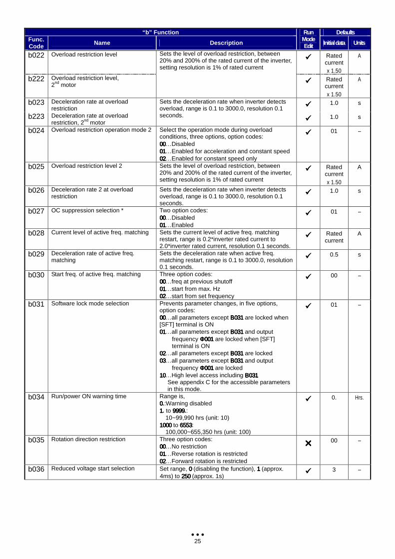
“b” Function Defaults Func. Code Name Description
Run Mode Edit Initial data Units
b022 Overload restriction level Rated
current x 1.50
A
b222 Overload restriction level, 2nd motor
Sets the level of overload restriction, between 20% and 200% of the rated current of the inverter, setting resolution is 1% of rated current
Rated current x 1.50
A
b023 Deceleration rate at overload restriction 1.0 s
b223 Deceleration rate at overload restriction, 2nd motor
Sets the deceleration rate when inverter detects overload, range is 0.1 to 3000.0, resolution 0.1 seconds.
1.0 s
b024 Overload restriction operation mode 2 Select the operation mode during overload conditions, three options, option codes: 00000000…Disabled 01010101…Enabled for acceleration and constant speed 02020202…Enabled for constant speed only
01 −
b025 Overload restriction level 2 Sets the level of overload restriction, between 20% and 200% of the rated current of the inverter, setting resolution is 1% of rated current
Rated current x 1.50
A
b026 Deceleration rate 2 at overload restriction
Sets the deceleration rate when inverter detects overload, range is 0.1 to 3000.0, resolution 0.1 seconds.
1.0 s
b027 OC suppression selection * Two option codes: 00000000…Disabled 01010101…Enabled
01 −
b028 Current level of active freq. matching Sets the current level of active freq. matching restart, range is 0.2*inverter rated current to 2.0*inverter rated current, resolution 0.1 seconds.
Rated current
A
b029 Deceleration rate of active freq. matching
Sets the deceleration rate when active freq. matching restart, range is 0.1 to 3000.0, resolution 0.1 seconds.
0.5 s
b030 Start freq. of active freq. matching Three option codes: 00000000…freq at previous shutoff 01010101…start from max. Hz 02020202…start from set frequency
00 −
b031 Software lock mode selection Prevents parameter changes, in five options, option codes: 00000000…all parameters except Β031Β031Β031Β031 are locked when [SFT] terminal is ON 01010101…all parameters except Β031Β031Β031Β031 and output
frequency Φ001Φ001Φ001Φ001 are locked when [SFT] terminal is ON
02020202…all parameters except Β031Β031Β031Β031 are locked 03030303…all parameters except Β031Β031Β031Β031 and output
frequency Φ001Φ001Φ001Φ001 are locked 10101010…High level access including Β031Β031Β031Β031
See appendix C for the accessible parameters in this mode.
01 −
b034 Run/power ON warning time Range is, 0000.:Warning disabled 1111. to 9999999999999999.:
10~99,990 hrs (unit: 10) 1000100010001000 to 6553655365536553:
100,000~655,350 hrs (unit: 100)
0. Hrs.
b035 Rotation direction restriction Three option codes: 00000000…No restriction 01010101…Reverse rotation is restricted 02020202…Forward rotation is restricted
00 −
b036 Reduced voltage start selection Set range, 0000 (disabling the function), 1111 (approx. 4ms) to 250250250250 (approx. 1s)
3 −
26
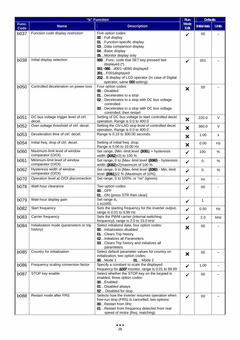
“b” Function Defaults Func. Code Name Description
Run Mode Edit Initial data Units
b037 Function code display restriction Five option codes: 00000000…Full display 01010101…Function-specific display 03030303…Data comparison display 04040404…Basic display 05050505…Monitor display only
00 −
b038 Initial display selection 000000000000…Func. code that SET key pressed last displayed.(*)
001001001001~060060060060…d001~d060 displayed 201201201201…F001displayed 202202202202…B display of LCD operator (In case of Digital
operator, same 000 000 000 000 setting)
001 −
b050 Controlled deceleration on power loss Four option codes: 00000000…Disabled 01010101…Decelerates to a stop 02020202…Decelerates to a stop with DC bus voltage
controlled 03030303…Decelerates to a stop with DC bus voltage
controlled, then restart
00 −
b051 DC bus voltage trigger level of ctrl. decel.
Setting of DC bus voltage to start controlled decel. operation. Range is 0.0 to 400.0 220.0 V
b052 Over-voltage threshold of ctrl. decel. Setting the OV-LAD stop level of controlled decel. operation. Range is 0.0 to 400.0 360.0 V
b053 Deceleration time of ctrl. decel. Range is 0.10 to 300.00 seconds. 1.00 s
b054 Initial freq. drop of ctrl. decel. Setting of initial freq. drop. Range is 0.00 to 10.00 Hz 0.00 Hz
b060 Maximum-limit level of window comparator (O/OI)
Set range, Min.-limit level (β061β061β061β061) + hysteresis width (β062β062β062β062)x2 to 100 %
100. %
b061 Minimum-limit level of window comparator (O/OI)
Set range, 0 to Max.-limit level (β060β060β060β060) - hysteresis width (β062β062β062β062)x2maximum of 100 % 0. %
b062 Hysteresis width of window comparator (O/OI)
Set range, 0 to Max.-limit level (β060β060β060β060) - Min.-limit level (β061β061β061β061)/2 % (Maximum of 10%) 0. %
b070 Operation level at O/OI disconnection Set range, 0 to 100%, or “no” (ignore) no -
b078 Watt-hour clearance Two option codes: 00000000…OFF 01010101…ON (press STR then clear)
00 -
b079 Watt-hour display gain Set range is, 1.to1000. 1.
b082 Start frequency Sets the starting frequency for the inverter output, range is 0.01 to 9.99 Hz 0.50 Hz
b083 Carrier frequency Sets the PWM carrier (internal switching frequency), range is 2.0 to 15.0 kHz 2.0 kHz
b084 Initialization mode (parameters or trip history)
Select initialized data, four option codes: 00000000…Initialization disabled 01010101…Clears Trip history 02020202…Initializes all Parameters 03030303…Clears Trip history and initializes all
parameters
00 −
b085 Country for initialization Select default parameter values for country on initialization, two option codes: 00000000…Mode 1 01010101… Mode 2
00 −
b086 Frequency scaling conversion factor Specify a constant to scale the displayed frequency for ∆007∆007∆007∆007 monitor, range is 0.01 to 99.99
1.00 −
b087 STOP key enable Select whether the STOP key on the keypad is enabled, three option codes: 00000000…Enabled 01010101…Disabled always 02020202… Disabled for stop
00 −
b088 Restart mode after FRS Selects how the inverter resumes operation when free-run stop (FRS) is cancelled, two options: 00000000…Restart from 0Hz 01010101…Restart from frequency detected from real
speed of motor (freq. matching)
00 −
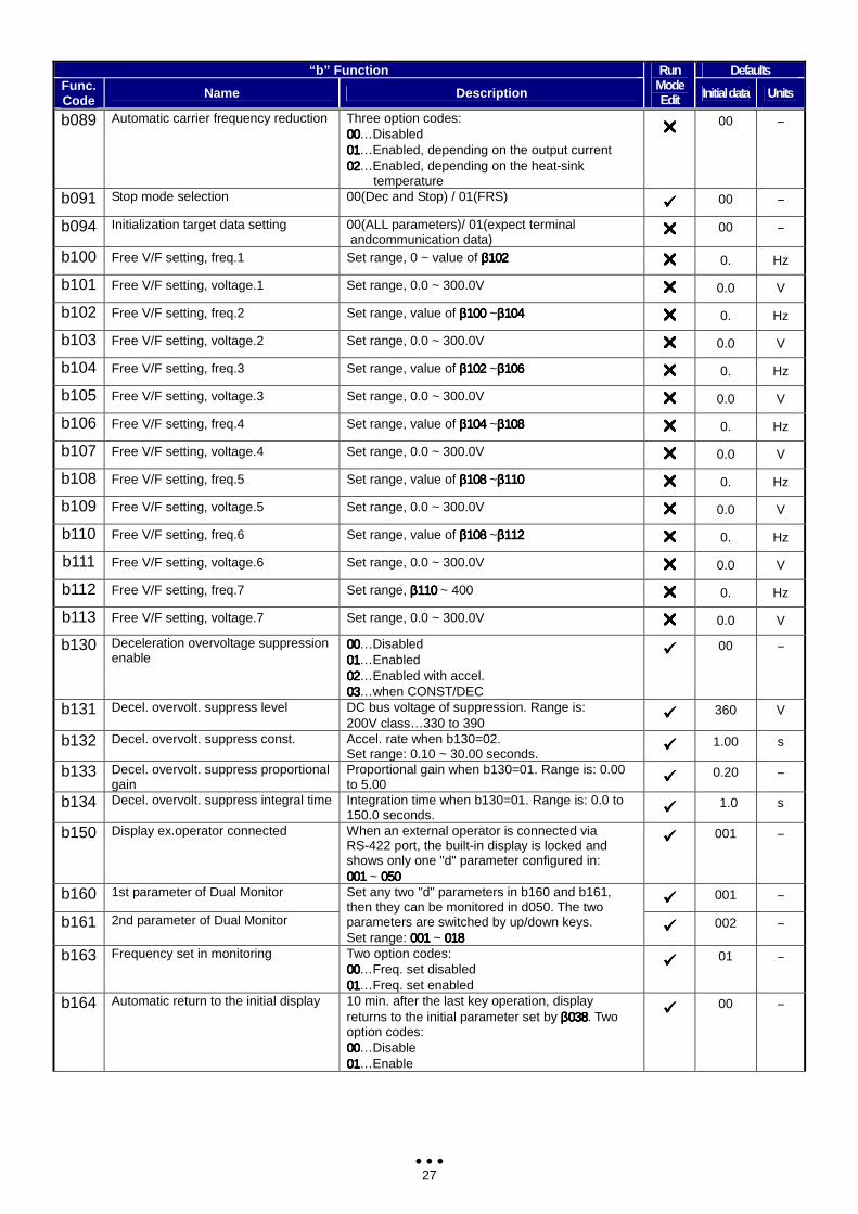
27
“b” Function Defaults Func. Code Name Description
Run Mode Edit Initial data Units
b089 Automatic carrier frequency reduction Three option codes: 00000000…Disabled 01010101…Enabled, depending on the output current 02020202…Enabled, depending on the heat-sink
temperature
00 −
b091 Stop mode selection 00(Dec and Stop) / 01(FRS) 00 −
b094 Initialization target data setting 00(ALL parameters)/ 01(expect terminal andcommunication data)
00 −
b100 Free V/F setting, freq.1 Set range, 0 ~ value of β102β102β102β102 0. Hz
b101 Free V/F setting, voltage.1 Set range, 0.0 ~ 300.0V 0.0 V
b102 Free V/F setting, freq.2 Set range, value of β100β100β100β100 ~β104β104β104β104 0. Hz
b103 Free V/F setting, voltage.2 Set range, 0.0 ~ 300.0V 0.0 V
b104 Free V/F setting, freq.3 Set range, value of β102β102β102β102 ~β106β106β106β106 0. Hz
b105 Free V/F setting, voltage.3 Set range, 0.0 ~ 300.0V 0.0 V
b106 Free V/F setting, freq.4 Set range, value of β104β104β104β104 ~β108β108β108β108 0. Hz
b107 Free V/F setting, voltage.4 Set range, 0.0 ~ 300.0V 0.0 V
b108 Free V/F setting, freq.5 Set range, value of β108β108β108β108 ~β110β110β110β110 0. Hz
b109 Free V/F setting, voltage.5 Set range, 0.0 ~ 300.0V 0.0 V
b110 Free V/F setting, freq.6 Set range, value of β108β108β108β108 ~β112β112β112β112 0. Hz
b111 Free V/F setting, voltage.6 Set range, 0.0 ~ 300.0V 0.0 V
b112 Free V/F setting, freq.7 Set range, β110β110β110β110 ~ 400 0. Hz
b113 Free V/F setting, voltage.7 Set range, 0.0 ~ 300.0V 0.0 V
b130 Deceleration overvoltage suppression enable
00000000…Disabled 01010101…Enabled 02020202…Enabled with accel. 03030303…when CONST/DEC
00 −
b131 Decel. overvolt. suppress level DC bus voltage of suppression. Range is: 200V class…330 to 390
360 V
b132 Decel. overvolt. suppress const. Accel. rate when b130=02. Set range: 0.10 ~ 30.00 seconds. 1.00 s
b133 Decel. overvolt. suppress proportional gain
Proportional gain when b130=01. Range is: 0.00 to 5.00 0.20 −
b134 Decel. overvolt. suppress integral time Integration time when b130=01. Range is: 0.0 to 150.0 seconds. 1.0 s
b150 Display ex.operator connected When an external operator is connected via RS-422 port, the built-in display is locked and shows only one "d" parameter configured in: 001001001001 ~ 050050050050
001 −
b160 1st parameter of Dual Monitor 001 −
b161 2nd parameter of Dual Monitor
Set any two "d" parameters in b160 and b161, then they can be monitored in d050. The two parameters are switched by up/down keys. Set range: 001001001001 ~ 018018018018
002 −
b163 Frequency set in monitoring Two option codes: 00000000…Freq. set disabled 01010101…Freq. set enabled
01 −
b164 Automatic return to the initial display 10 min. after the last key operation, display returns to the initial parameter set by β038β038β038β038. Two option codes: 00000000…Disable 01010101…Enable
00 −
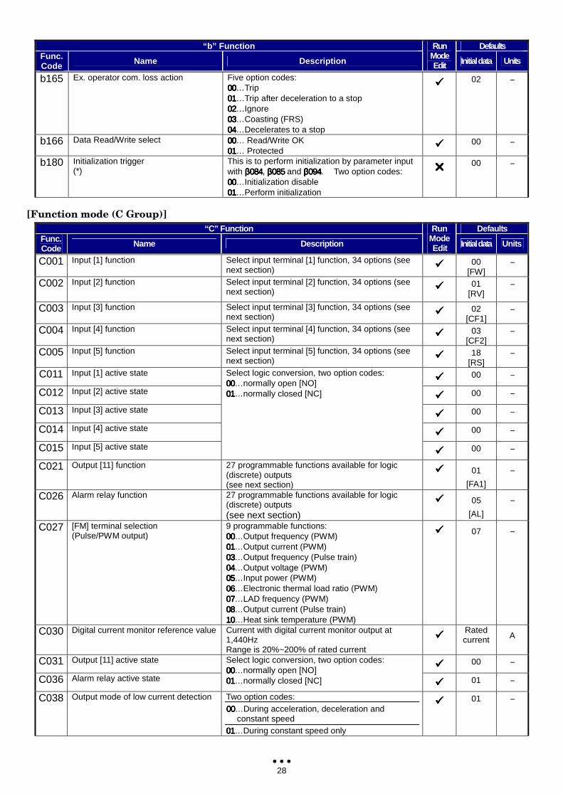
28
“b” Function Defaults Func. Code Name Description
Run Mode Edit Initial data Units
b165 Ex. operator com. loss action Five option codes: 00000000…Trip 01010101…Trip after deceleration to a stop 02020202…Ignore 03030303…Coasting (FRS) 04040404…Decelerates to a stop
02 −
b166 Data Read/Write select 00000000… Read/Write OK 01010101… Protected
00 −
b180 Initialization trigger (*)
This is to perform initialization by parameter input with β084β084β084β084, β085β085β085β085 and β094β094β094β094. Two option codes: 00000000…Initialization disable 01010101…Perform initialization
00 −
[Function mode (C Group)]
“C” Function Defaults Func. Code Name Description
Run Mode Edit Initial data Units
C001 Input [1] function Select input terminal [1] function, 34 options (see next section) 00
[FW] −
C002 Input [2] function Select input terminal [2] function, 34 options (see next section) 01
[RV] −
C003 Input [3] function Select input terminal [3] function, 34 options (see next section) 02
[CF1] −
C004 Input [4] function Select input terminal [4] function, 34 options (see next section) 03
[CF2] −
C005 Input [5] function Select input terminal [5] function, 34 options (see next section) 18
[RS] −
C011 Input [1] active state 00 −
C012 Input [2] active state 00 −
C013 Input [3] active state 00 −
C014 Input [4] active state 00 −
C015 Input [5] active state
Select logic conversion, two option codes: 00000000…normally open [NO] 01010101…normally closed [NC]
00 −
C021 Output [11] function 27 programmable functions available for logic (discrete) outputs (see next section)
01
[FA1]
−
C026 Alarm relay function 27 programmable functions available for logic (discrete) outputs (see next section)
05
[AL]
−
C027 [FM] terminal selection (Pulse/PWM output)
9 programmable functions: 00000000…Output frequency (PWM) 01010101…Output current (PWM) 03030303…Output frequency (Pulse train) 04040404…Output voltage (PWM) 05050505…Input power (PWM) 06060606…Electronic thermal load ratio (PWM) 07070707…LAD frequency (PWM) 08080808…Output current (Pulse train) 10101010…Heat sink temperature (PWM)
07 −
C030 Digital current monitor reference value Current with digital current monitor output at 1,440Hz Range is 20%~200% of rated current
Rated current A
C031 Output [11] active state 00 −
C036 Alarm relay active state
Select logic conversion, two option codes: 00000000…normally open [NO] 00001111…normally closed [NC] 01 −
C038 Output mode of low current detection Two option codes: 00000000…During acceleration, deceleration and
constant speed 01010101…During constant speed only
01 −
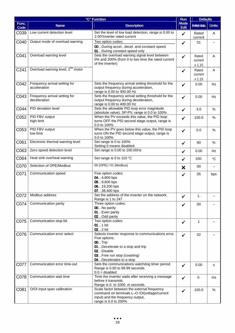
29
“C” Function Defaults Func. Code Name Description
Run Mode Edit Initial data Units
C039 Low current detection level Set the level of low load detection, range is 0.00 to 2.00*inverter rated current Rated
current A
C040 Output mode of overload warning Two option codes: 00000000…During accel., decel. and constant speed 01010101…During constant speed only
01 −
C041 Overload warning level Rated
current x 1.15
A
C241 Overload warning level, 2nd motor
Sets the overload warning signal level between 0% and 200% (from 0 to two time the rated current of the inverter)
Rated current x 1.15
A
C042 Frequency arrival setting for acceleration
Sets the frequency arrival setting threshold for the output frequency during acceleration, range is 0.00 to 400.00 Hz
0.00 Hz
C043 Frequency arrival setting for deceleration
Sets the frequency arrival setting threshold for the output frequency during deceleration, range is 0.00 to 400.00 Hz
0.00 Hz
C044 PID deviation level Sets the allowable PID loop error magnitude (absolute value), SP-PV, range is 0.0 to 100% 3.0 %
C052 PID FBV output high limit
When the PV exceeds this value, the PID loop turns OFF the PID second stage output, range is 0.0 to 100%
100.0 %
C053 PID FBV output low limit
When the PV goes below this value, the PID loop turns ON the PID second stage output, range is 0.0 to 100%
0.0 %
C061 Electronic thermal warning level Set range is 0 to 100% Setting 0 means disabled. 90 %
C063 Zero speed detection level Set range is 0.00 to 100.00Hz 0.00 Hz
C064 Heat sink overheat warning Set range is 0 to 110 °C 100. °C
C070 Selection of OPE/Modbus 00 (OPE) / 01 (Modbus) 00 −
C071 Communication speed Five option codes: 04040404…4,800 bps 05050505…9,600 bps 06060606…19,200 bps 07070707…38,400 bps
05 bps
C072 Modbus address Set the address of the inverter on the network. Range is 1 to 247 1. −
C074 Communication parity Three option codes: 00000000…No parity 01010101…Even parity 02020202…Odd parity
00 −
C075 Communication stop bit Two option codes: 01010101…1 bit 02020202…2 bit
1 −
C076 Communication error select Selects inverter response to communications error. Five options: 00000000…Trip 01010101…Decelerate to a stop and trip 02020202…Disable 03030303…Free run stop (coasting) 04040404…Decelerates to a stop
02 −
C077 Communication error time-out Sets the communications watchdog timer period. Range is 0.00 to 99.99 seconds. 0.0 = disabled
0.00 s
C078 Communication wait time Time the inverter waits after receiving a message before it transmits. Range is 0. to 1000. m seconds.
0. ms
C081 O/OI input span calibration Scale factor between the external frequency command on terminals L–O /OI(voltage/current input) and the frequency output, range is 0.0 to 200%
100.0 %
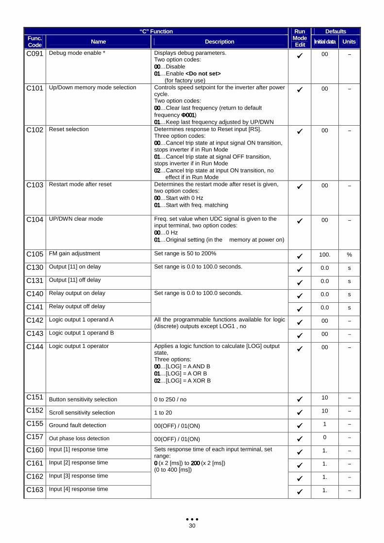
30
“C” Function Defaults Func. Code Name Description
Run Mode Edit Initial data Units
C091 Debug mode enable * Displays debug parameters. Two option codes: 00000000…Disable 01010101…Enable <Do not set> (for factory use)
00 −
C101 Up/Down memory mode selection Controls speed setpoint for the inverter after power cycle. Two option codes: 00000000…Clear last frequency (return to default frequency Φ001Φ001Φ001Φ001) 01010101…Keep last frequency adjusted by UP/DWN
00 −
C102 Reset selection Determines response to Reset input [RS]. Three option codes: 00000000…Cancel trip state at input signal ON transition, stops inverter if in Run Mode 01010101…Cancel trip state at signal OFF transition, stops inverter if in Run Mode 02020202…Cancel trip state at input ON transition, no
effect if in Run Mode
00 −
C103 Restart mode after reset Determines the restart mode after reset is given, two option codes: 00000000…Start with 0 Hz 01010101…Start with freq. matching
00 −
C104 UP/DWN clear mode Freq. set value when UDC signal is given to the input terminal, two option codes: 00000000…0 Hz 01010101…Original setting (in the memory at power on)
00 −
C105 FM gain adjustment Set range is 50 to 200% 100. %
C130 Output [11] on delay 0.0 s
C131 Output [11] off delay
Set range is 0.0 to 100.0 seconds.
0.0 s
C140 Relay output on delay 0.0 s
C141 Relay output off delay
Set range is 0.0 to 100.0 seconds.
0.0 s
C142 Logic output 1 operand A 00 −
C143 Logic output 1 operand B
All the programmable functions available for logic (discrete) outputs except LOG1 , no
00 −
C144 Logic output 1 operator Applies a logic function to calculate [LOG] output state, Three options: 00000000…[LOG] = A AND B 01010101…[LOG] = A OR B 02020202…[LOG] = A XOR B
00 −
C151 Button sensitivity selection 0 to 250 / no 10 −
C152 Scroll sensitivity selection 1 to 20 10 −
C155 Ground fault detection 00(OFF) / 01(ON) 1 −
C157 Out phase loss detection 00(OFF) / 01(ON) 0 −
C160 Input [1] response time 1. −
C161 Input [2] response time 1. −
C162 Input [3] response time 1. −
C163 Input [4] response time
Sets response time of each input terminal, set range: 0 0 0 0 (x 2 [ms]) to 200 200 200 200 (x 2 [ms]) (0 to 400 [ms])
1. −
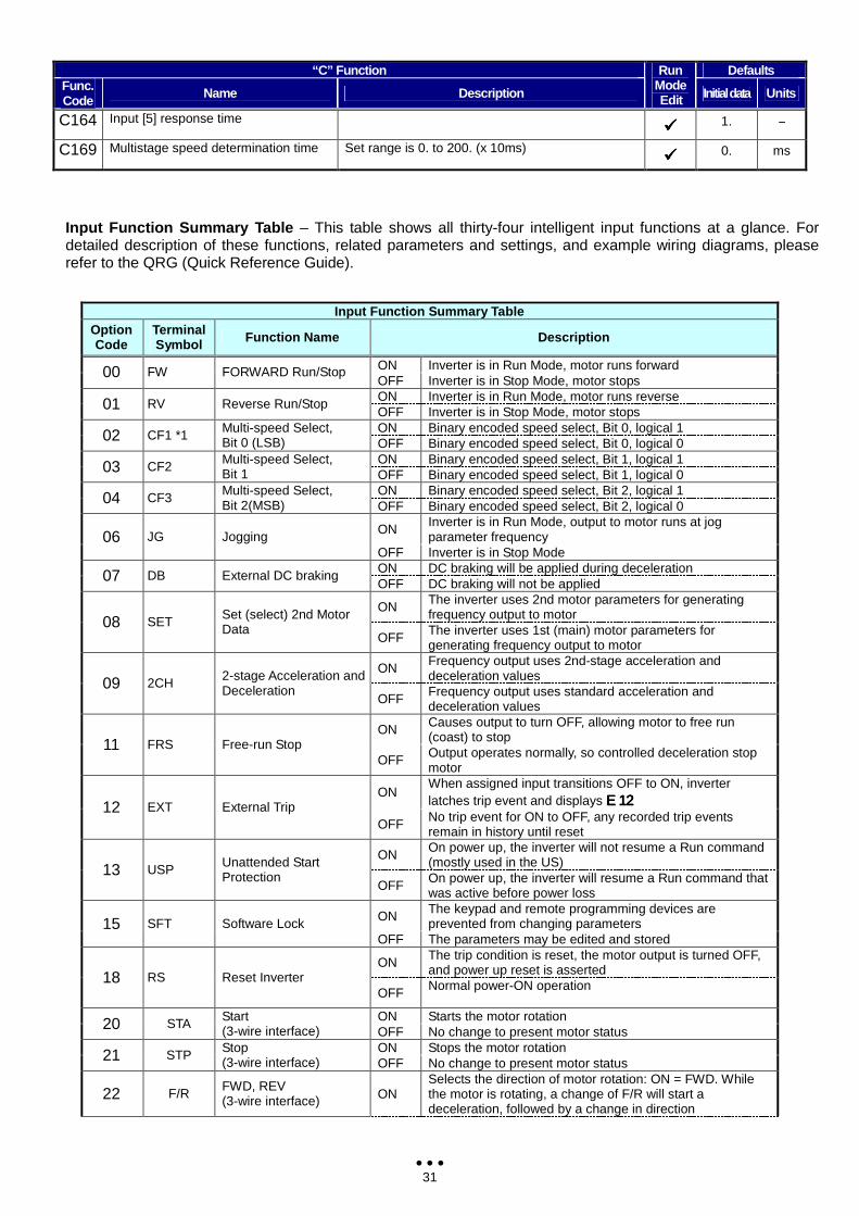
31
“C” Function Defaults Func. Code Name Description
Run Mode Edit Initial data Units
C164 Input [5] response time 1. −
C169 Multistage speed determination time Set range is 0. to 200. (x 10ms) 0. ms
Input Function Summary Table – This table shows all thirty-four intelligent input functions at a glance. For detailed description of these functions, related parameters and settings, and example wiring diagrams, please refer to the QRG (Quick Reference Guide).
Input Function Summary Table
Option Code
Terminal Symbol Function Name Description
ON Inverter is in Run Mode, motor runs forward 00 FW FORWARD Run/Stop OFF Inverter is in Stop Mode, motor stops ON Inverter is in Run Mode, motor runs reverse 01 RV Reverse Run/Stop OFF Inverter is in Stop Mode, motor stops ON Binary encoded speed select, Bit 0, logical 1 02 CF1 *1 Multi-speed Select,
Bit 0 (LSB) OFF Binary encoded speed select, Bit 0, logical 0 ON Binary encoded speed select, Bit 1, logical 1 03 CF2 Multi-speed Select,
Bit 1 OFF Binary encoded speed select, Bit 1, logical 0 ON Binary encoded speed select, Bit 2, logical 1 04 CF3 Multi-speed Select,
Bit 2(MSB) OFF Binary encoded speed select, Bit 2, logical 0
ON Inverter is in Run Mode, output to motor runs at jog parameter frequency 06 JG Jogging
OFF Inverter is in Stop Mode ON DC braking will be applied during deceleration 07 DB External DC braking OFF DC braking will not be applied
ON The inverter uses 2nd motor parameters for generating frequency output to motor 08 SET Set (select) 2nd Motor
Data OFF The inverter uses 1st (main) motor parameters for
generating frequency output to motor
ON Frequency output uses 2nd-stage acceleration and deceleration values 09 2CH 2-stage Acceleration and
Deceleration OFF Frequency output uses standard acceleration and
deceleration values
ON Causes output to turn OFF, allowing motor to free run (coast) to stop 11 FRS Free-run Stop
OFF Output operates normally, so controlled deceleration stop motor
ON When assigned input transitions OFF to ON, inverter latches trip event and displays Ε 12Ε 12Ε 12Ε 12 12 EXT External Trip
OFF No trip event for ON to OFF, any recorded trip events remain in history until reset
ON On power up, the inverter will not resume a Run command (mostly used in the US) 13 USP Unattended Start
Protection OFF On power up, the inverter will resume a Run command that
was active before power loss
ON The keypad and remote programming devices are prevented from changing parameters 15 SFT Software Lock
OFF The parameters may be edited and stored
ON The trip condition is reset, the motor output is turned OFF, and power up reset is asserted 18 RS Reset Inverter
OFF Normal power-ON operation
ON Starts the motor rotation 20 STA Start (3-wire interface) OFF No change to present motor status
ON Stops the motor rotation 21 STP Stop (3-wire interface) OFF No change to present motor status
22 F/R FWD, REV (3-wire interface) ON
Selects the direction of motor rotation: ON = FWD. While the motor is rotating, a change of F/R will start a deceleration, followed by a change in direction
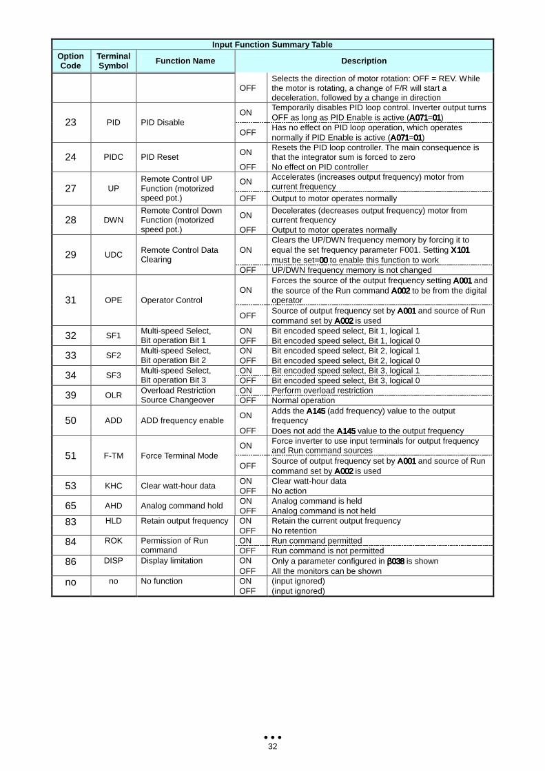
32
Input Function Summary Table Option Code
Terminal Symbol Function Name Description
OFF
Selects the direction of motor rotation: OFF = REV. While the motor is rotating, a change of F/R will start a deceleration, followed by a change in direction
ON Temporarily disables PID loop control. Inverter output turns OFF as long as PID Enable is active (Α071Α071Α071Α071=01010101) 23 PID PID Disable
OFF Has no effect on PID loop operation, which operates normally if PID Enable is active (Α071Α071Α071Α071=01010101)
ON Resets the PID loop controller. The main consequence is that the integrator sum is forced to zero 24 PIDC PID Reset
OFF No effect on PID controller
ON Accelerates (increases output frequency) motor from current frequency 27 UP
Remote Control UP Function (motorized speed pot.) OFF Output to motor operates normally
ON Decelerates (decreases output frequency) motor from current frequency 28 DWN
Remote Control Down Function (motorized speed pot.) OFF Output to motor operates normally
ON Clears the UP/DWN frequency memory by forcing it to equal the set frequency parameter F001. Setting Χ101Χ101Χ101Χ101 must be set=00000000 to enable this function to work 29 UDC Remote Control Data
Clearing OFF UP/DWN frequency memory is not changed
ON Forces the source of the output frequency setting Α001Α001Α001Α001 and the source of the Run command Α002Α002Α002Α002 to be from the digital operator 31 OPE Operator Control
OFF Source of output frequency set by Α001Α001Α001Α001 and source of Run command set by Α002Α002Α002Α002 is used
ON Bit encoded speed select, Bit 1, logical 1 32 SF1 Multi-speed Select, Bit operation Bit 1 OFF Bit encoded speed select, Bit 1, logical 0
ON Bit encoded speed select, Bit 2, logical 1 33 SF2 Multi-speed Select, Bit operation Bit 2 OFF Bit encoded speed select, Bit 2, logical 0
ON Bit encoded speed select, Bit 3, logical 1 34 SF3 Multi-speed Select, Bit operation Bit 3 OFF Bit encoded speed select, Bit 3, logical 0
ON Perform overload restriction 39 OLR Overload Restriction Source Changeover OFF Normal operation
ON Adds the Α145Α145Α145Α145 (add frequency) value to the output frequency 50 ADD ADD frequency enable
OFF Does not add the Α145Α145Α145Α145 value to the output frequency
ON Force inverter to use input terminals for output frequency and Run command sources
51 F-TM Force Terminal Mode OFF
Source of output frequency set by Α001Α001Α001Α001 and source of Run command set by Α002Α002Α002Α002 is used
ON Clear watt-hour data 53 KHC Clear watt-hour data OFF No action ON Analog command is held 65 AHD Analog command hold OFF Analog command is not held ON Retain the current output frequency 83 HLD Retain output frequency OFF No retention ON Run command permitted 84 ROK Permission of Run
command OFF Run command is not permitted ON Only a parameter configured in β038β038β038β038 is shown 86 DISP Display limitation OFF All the monitors can be shown ON (input ignored) no no No function OFF (input ignored)
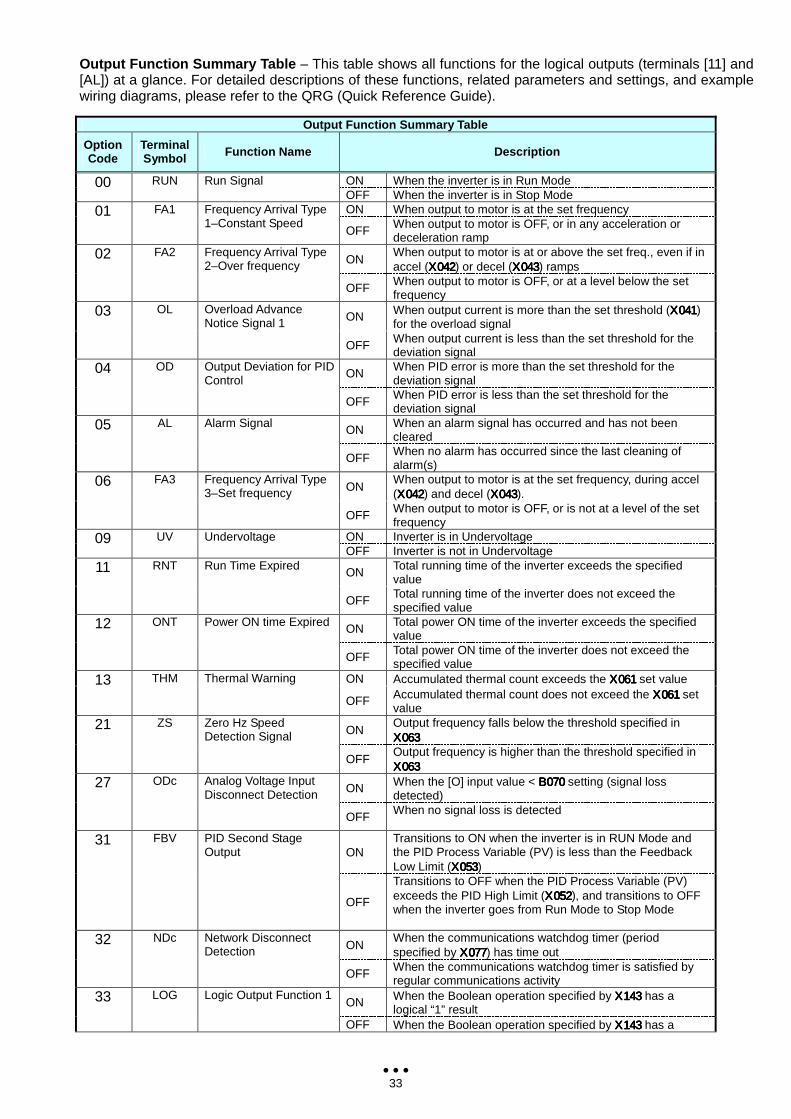
33
Output Function Summary Table – This table shows all functions for the logical outputs (terminals [11] and [AL]) at a glance. For detailed descriptions of these functions, related parameters and settings, and example wiring diagrams, please refer to the QRG (Quick Reference Guide).
Output Function Summary Table
Option Code
Terminal Symbol Function Name Description
ON When the inverter is in Run Mode 00 RUN Run Signal OFF When the inverter is in Stop Mode ON When output to motor is at the set frequency 01 FA1 Frequency Arrival Type
1–Constant Speed OFF When output to motor is OFF, or in any acceleration or
deceleration ramp
ON When output to motor is at or above the set freq., even if in accel (Χ042Χ042Χ042Χ042) or decel (Χ043Χ043Χ043Χ043) ramps
02 FA2 Frequency Arrival Type 2–Over frequency
OFF When output to motor is OFF, or at a level below the set frequency
ON When output current is more than the set threshold (Χ041Χ041Χ041Χ041) for the overload signal
03 OL Overload Advance Notice Signal 1
OFF When output current is less than the set threshold for the deviation signal
ON When PID error is more than the set threshold for the deviation signal
04 OD Output Deviation for PID Control
OFF When PID error is less than the set threshold for the deviation signal
ON When an alarm signal has occurred and has not been cleared
05 AL Alarm Signal
OFF When no alarm has occurred since the last cleaning of alarm(s)
ON When output to motor is at the set frequency, during accel (Χ042Χ042Χ042Χ042) and decel (Χ043Χ043Χ043Χ043).
06 FA3 Frequency Arrival Type 3–Set frequency
OFF When output to motor is OFF, or is not at a level of the set frequency
ON Inverter is in Undervoltage 09 UV Undervoltage OFF Inverter is not in Undervoltage
ON Total running time of the inverter exceeds the specified value
11 RNT Run Time Expired
OFF Total running time of the inverter does not exceed the specified value
ON Total power ON time of the inverter exceeds the specified value
12 ONT Power ON time Expired
OFF Total power ON time of the inverter does not exceed the specified value
ON Accumulated thermal count exceeds the Χ061Χ061Χ061Χ061 set value 13 THM Thermal Warning
OFF Accumulated thermal count does not exceed the Χ061Χ061Χ061Χ061 set value
ON Output frequency falls below the threshold specified in Χ063Χ063Χ063Χ063
21 ZS Zero Hz Speed Detection Signal
OFF Output frequency is higher than the threshold specified in Χ063Χ063Χ063Χ063
ON When the [O] input value < Β070Β070Β070Β070 setting (signal loss detected)
27 ODc Analog Voltage Input Disconnect Detection
OFF When no signal loss is detected
ON Transitions to ON when the inverter is in RUN Mode and the PID Process Variable (PV) is less than the Feedback Low Limit (Χ053Χ053Χ053Χ053)
31 FBV PID Second Stage Output
OFF
Transitions to OFF when the PID Process Variable (PV) exceeds the PID High Limit (Χ052Χ052Χ052Χ052), and transitions to OFF when the inverter goes from Run Mode to Stop Mode
ON When the communications watchdog timer (period specified by Χ077Χ077Χ077Χ077) has time out
32 NDc Network Disconnect Detection
OFF When the communications watchdog timer is satisfied by regular communications activity
ON When the Boolean operation specified by Χ143Χ143Χ143Χ143 has a logical “1” result
33 LOG Logic Output Function 1
OFF When the Boolean operation specified by Χ143Χ143Χ143Χ143 has a
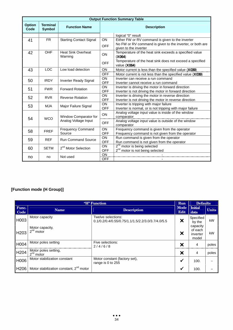
34
Output Function Summary Table
Option Code
Terminal Symbol Function Name Description
logical “0” result ON Either FW or RV command is given to the inverter 41 FR Starting Contact Signal
OFF No FW or RV command is given to the inverter, or both are given to the inverter
ON Temperature of the heat sink exceeds a specified value (Χ064Χ064Χ064Χ064)
42 OHF Heat Sink Overheat Warning
OFF Temperature of the heat sink does not exceed a specified value (Χ064Χ064Χ064Χ064)
ON Motor current is less than the specified value (Χ039Χ039Χ039Χ039) 43 LOC Low load detection OFF Motor current is not less than the specified value (Χ039Χ039Χ039Χ039) ON Inverter can receive a run command 50 IRDY Inverter Ready Signal OFF Inverter cannot receive a run command ON Inverter is driving the motor in forward direction 51 FWR Forward Rotation OFF Inverter is not driving the motor in forward direction ON Inverter is driving the motor in reverse direction 52 RVR Reverse Rotation OFF Inverter is not driving the motor in reverse direction ON Inverter is tripping with major failure 53 MJA Major Failure Signal OFF Inverter is normal, or is not tripping with major failure
ON Analog voltage input value is inside of the window comparator 54 WCO Window Comparator for
Analog Voltage Input OFF Analog voltage input value is outside of the window
comparator ON Frequency command is given from the operator 58 FREF Frequency Command
Source OFF Frequency command is not given from the operator ON Run command is given from the operator 59 REF Run Command Source OFF Run command is not given from the operator ON 2nd motor is being selected 60 SETM 2nd Motor Selection OFF 2nd motor is not being selected ON - no no Not used OFF -
[Function mode (H Group)]
“H” Function Defaults
Func.
Code Name Description
Run
Mode
Edit
Initial
data Units
H003 Motor capacity
kW
H203
Motor capacity, 2nd motor
Twelve selections: 0.1/0.2/0.4/0.55/0.75/1.1/1.5/2.2/3.0/3.7/4.0/5.5
Specified by the
capacity of each inverter model
kW
H004 Motor poles setting
4 poles
H204 Motor poles setting, 2nd motor
Five selections: 2 / 4 / 6 / 8
4 poles
H006 Motor stabilization constant
100. −
H206 Motor stabilization constant, 2nd motor
Motor constant (factory set), range is 0 to 255
100. −
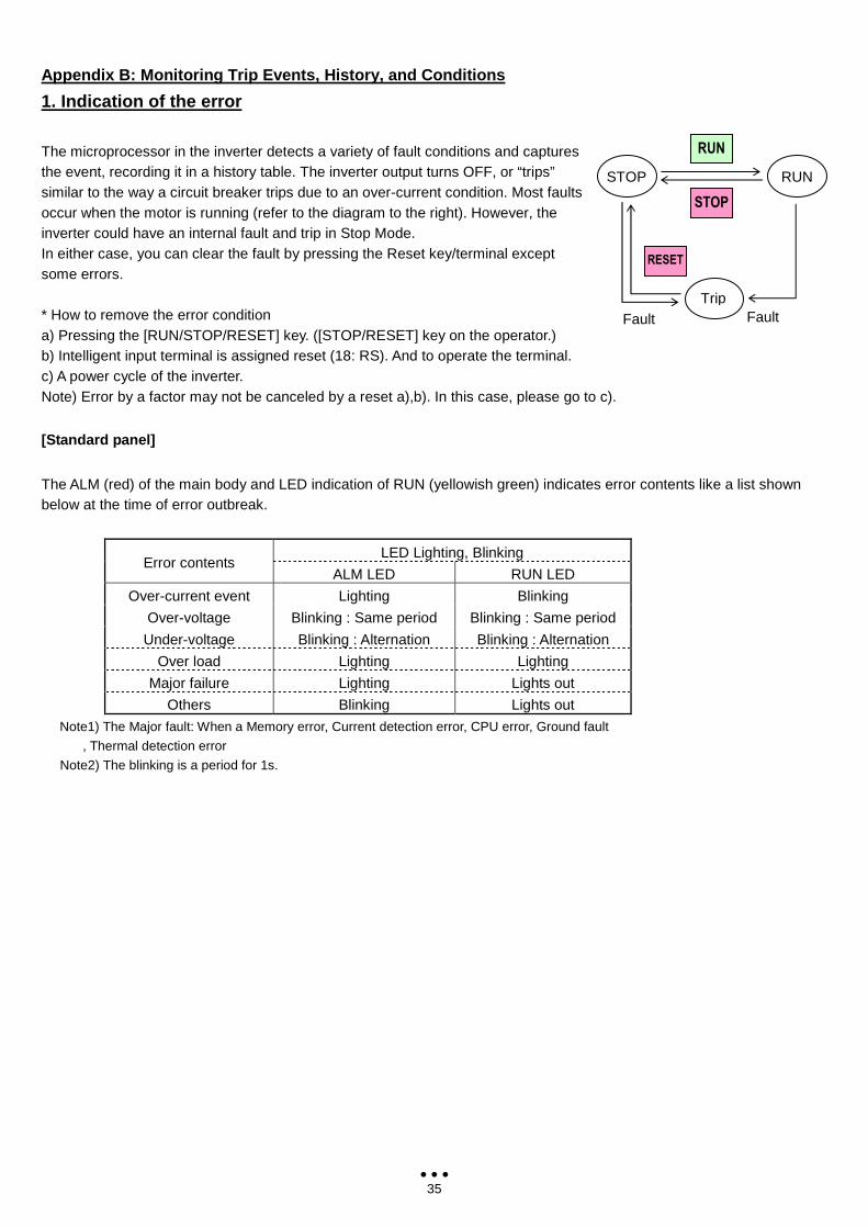
35
Appendix B: Monitoring Trip Events, History, and Co nditions
1. Indication of the error
The microprocessor in the inverter detects a variety of fault conditions and captures the event, recording it in a history table. The inverter output turns OFF, or “trips” similar to the way a circuit breaker trips due to an over-current condition. Most faults occur when the motor is running (refer to the diagram to the right). However, the inverter could have an internal fault and trip in Stop Mode. In either case, you can clear the fault by pressing the Reset key/terminal except some errors. * How to remove the error condition a) Pressing the [RUN/STOP/RESET] key. ([STOP/RESET] key on the operator.) b) Intelligent input terminal is assigned reset (18: RS). And to operate the terminal. c) A power cycle of the inverter. Note) Error by a factor may not be canceled by a reset a),b). In this case, please go to c).
[Standard panel]
The ALM (red) of the main body and LED indication of RUN (yellowish green) indicates error contents like a list shown below at the time of error outbreak.
LED Lighting, Blinking Error contents
ALM LED RUN LED
Over-current event Lighting Blinking
Over-voltage Blinking : Same period Blinking : Same period
Under-voltage Blinking : Alternation Blinking : Alternation
Over load Lighting Lighting
Major failure Lighting Lights out
Others Blinking Lights out
Note1) The Major fault: When a Memory error, Current detection error, CPU error, Ground fault
, Thermal detection error
Note2) The blinking is a period for 1s.
RUN
STOP
RESET
RUN
Trip Fault Fault
STOP
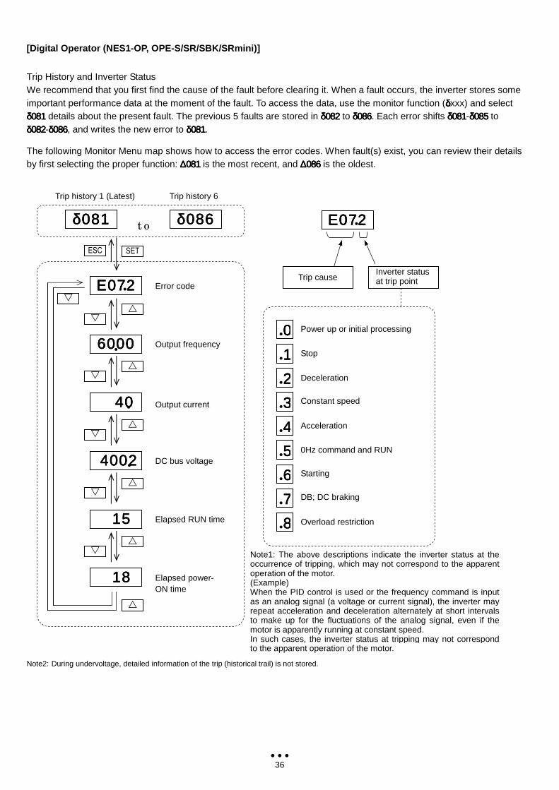
36
[Digital Operator (NES1-OP, OPE-S/SR/SBK/SRmini)]
Trip History and Inverter Status We recommend that you first find the cause of the fault before clearing it. When a fault occurs, the inverter stores some important performance data at the moment of the fault. To access the data, use the monitor function (δδδδxxx) and select δ081δ081δ081δ081 details about the present fault. The previous 5 faults are stored in δ082δ082δ082δ082 to δ086δ086δ086δ086. Each error shifts δ081δ081δ081δ081-δ085δ085δ085δ085 to δ082δ082δ082δ082-δ086δ086δ086δ086, and writes the new error to δ081δ081δ081δ081.
The following Monitor Menu map shows how to access the error codes. When fault(s) exist, you can review their details by first selecting the proper function: ∆081∆081∆081∆081 is the most recent, and ∆086∆086∆086∆086 is the oldest.
Note2: During undervoltage, detailed information of the trip (historical trail) is not stored.
Note1: The above descriptions indicate the inverter status at the occurrence of tripping, which may not correspond to the apparent operation of the motor. (Example) When the PID control is used or the frequency command is input as an analog signal (a voltage or current signal), the inverter may repeat acceleration and deceleration alternately at short intervals to make up for the fluctuations of the analog signal, even if the motor is apparently running at constant speed. In such cases, the inverter status at tripping may not correspond to the apparent operation of the motor.
Trip cause Inverter status at trip point
.0000
.1111
.2222
.3333
.4444
.5555
.6666
.7777
.8888
ΕΕΕΕ 0 720 720 720 72 .
Power up or initial processing
Stop
Deceleration
Constant speed
Acceleration
0Hz command and RUN
Starting
DB; DC braking
Overload restriction
4 0 4 0 4 0 4 0
Ε 0 72Ε 0 72Ε 0 72Ε 0 72
δ0 8 1δ0 8 1δ0 8 1δ0 8 1
SET ESC
Trip history 1 (Latest)
Error code
t o
Trip history 6
δ0 8 6δ0 8 6δ0 8 6δ0 8 6
.
.
6 00 06 00 06 00 06 00 0 .
4 00 2 4 00 2 4 00 2 4 00 2
1 5 1 5 1 5 1 5
1 8 1 8 1 8 1 8
.
Output frequency
Output current
DC bus voltage
Elapsed RUN time
Elapsed power- ON time
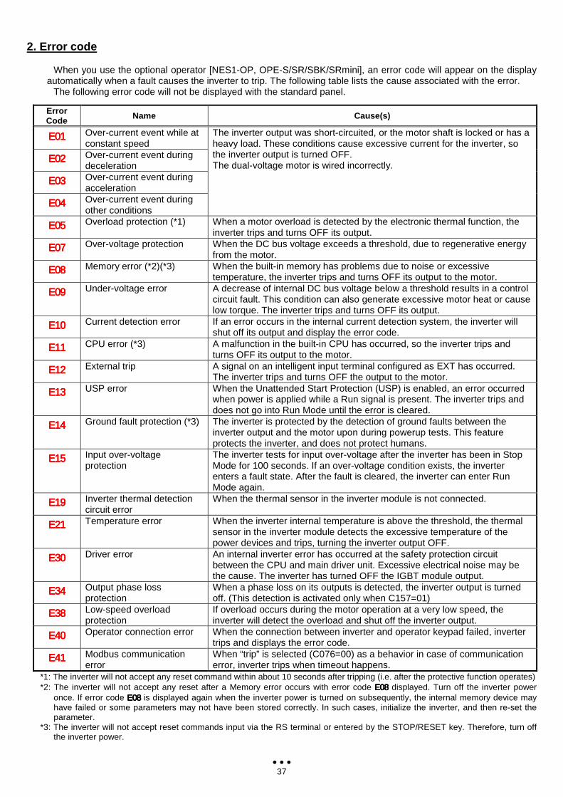
37
2. Error code
When you use the optional operator [NES1-OP, OPE-S/SR/SBK/SRmini], an error code will appear on the display automatically when a fault causes the inverter to trip. The following table lists the cause associated with the error.
The following error code will not be displayed with the standard panel.
Error Code Name Cause(s)
Ε01Ε01Ε01Ε01 Over-current event while at constant speed
Ε02Ε02Ε02Ε02 Over-current event during deceleration
Ε03Ε03Ε03Ε03 Over-current event during acceleration
Ε04Ε04Ε04Ε04 Over-current event during other conditions
The inverter output was short-circuited, or the motor shaft is locked or has a heavy load. These conditions cause excessive current for the inverter, so the inverter output is turned OFF. The dual-voltage motor is wired incorrectly.
Ε05Ε05Ε05Ε05 Overload protection (*1) When a motor overload is detected by the electronic thermal function, the inverter trips and turns OFF its output.
Ε07Ε07Ε07Ε07 Over-voltage protection When the DC bus voltage exceeds a threshold, due to regenerative energy from the motor.
Ε08Ε08Ε08Ε08 Memory error (*2)(*3) When the built-in memory has problems due to noise or excessive temperature, the inverter trips and turns OFF its output to the motor.
Ε09Ε09Ε09Ε09 Under-voltage error A decrease of internal DC bus voltage below a threshold results in a control circuit fault. This condition can also generate excessive motor heat or cause low torque. The inverter trips and turns OFF its output.
Ε10Ε10Ε10Ε10 Current detection error If an error occurs in the internal current detection system, the inverter will shut off its output and display the error code.
Ε11Ε11Ε11Ε11 CPU error (*3) A malfunction in the built-in CPU has occurred, so the inverter trips and turns OFF its output to the motor.
Ε12Ε12Ε12Ε12 External trip A signal on an intelligent input terminal configured as EXT has occurred. The inverter trips and turns OFF the output to the motor.
Ε13Ε13Ε13Ε13 USP error When the Unattended Start Protection (USP) is enabled, an error occurred when power is applied while a Run signal is present. The inverter trips and does not go into Run Mode until the error is cleared.
Ε14Ε14Ε14Ε14 Ground fault protection (*3) The inverter is protected by the detection of ground faults between the inverter output and the motor upon during powerup tests. This feature protects the inverter, and does not protect humans.
Ε15Ε15Ε15Ε15 Input over-voltage protection
The inverter tests for input over-voltage after the inverter has been in Stop Mode for 100 seconds. If an over-voltage condition exists, the inverter enters a fault state. After the fault is cleared, the inverter can enter Run Mode again.
Ε19Ε19Ε19Ε19 Inverter thermal detection circuit error
When the thermal sensor in the inverter module is not connected.
Ε21Ε21Ε21Ε21 Temperature error When the inverter internal temperature is above the threshold, the thermal sensor in the inverter module detects the excessive temperature of the power devices and trips, turning the inverter output OFF.
Ε30Ε30Ε30Ε30 Driver error An internal inverter error has occurred at the safety protection circuit between the CPU and main driver unit. Excessive electrical noise may be the cause. The inverter has turned OFF the IGBT module output.
Ε34Ε34Ε34Ε34 Output phase loss protection
When a phase loss on its outputs is detected, the inverter output is turned off. (This detection is activated only when C157=01)
Ε38Ε38Ε38Ε38 Low-speed overload protection
If overload occurs during the motor operation at a very low speed, the inverter will detect the overload and shut off the inverter output.
Ε40Ε40Ε40Ε40 Operator connection error When the connection between inverter and operator keypad failed, inverter trips and displays the error code.
Ε41Ε41Ε41Ε41 Modbus communication error
When “trip” is selected (C076=00) as a behavior in case of communication error, inverter trips when timeout happens.
*1: The inverter will not accept any reset command within about 10 seconds after tripping (i.e. after the protective function operates) *2: The inverter will not accept any reset after a Memory error occurs with error code Ε08Ε08Ε08Ε08 displayed. Turn off the inverter power
once. If error code Ε08Ε08Ε08Ε08 is displayed again when the inverter power is turned on subsequently, the internal memory device may have failed or some parameters may not have been stored correctly. In such cases, initialize the inverter, and then re-set the parameter.
*3: The inverter will not accept reset commands input via the RS terminal or entered by the STOP/RESET key. Therefore, turn off the inverter power.
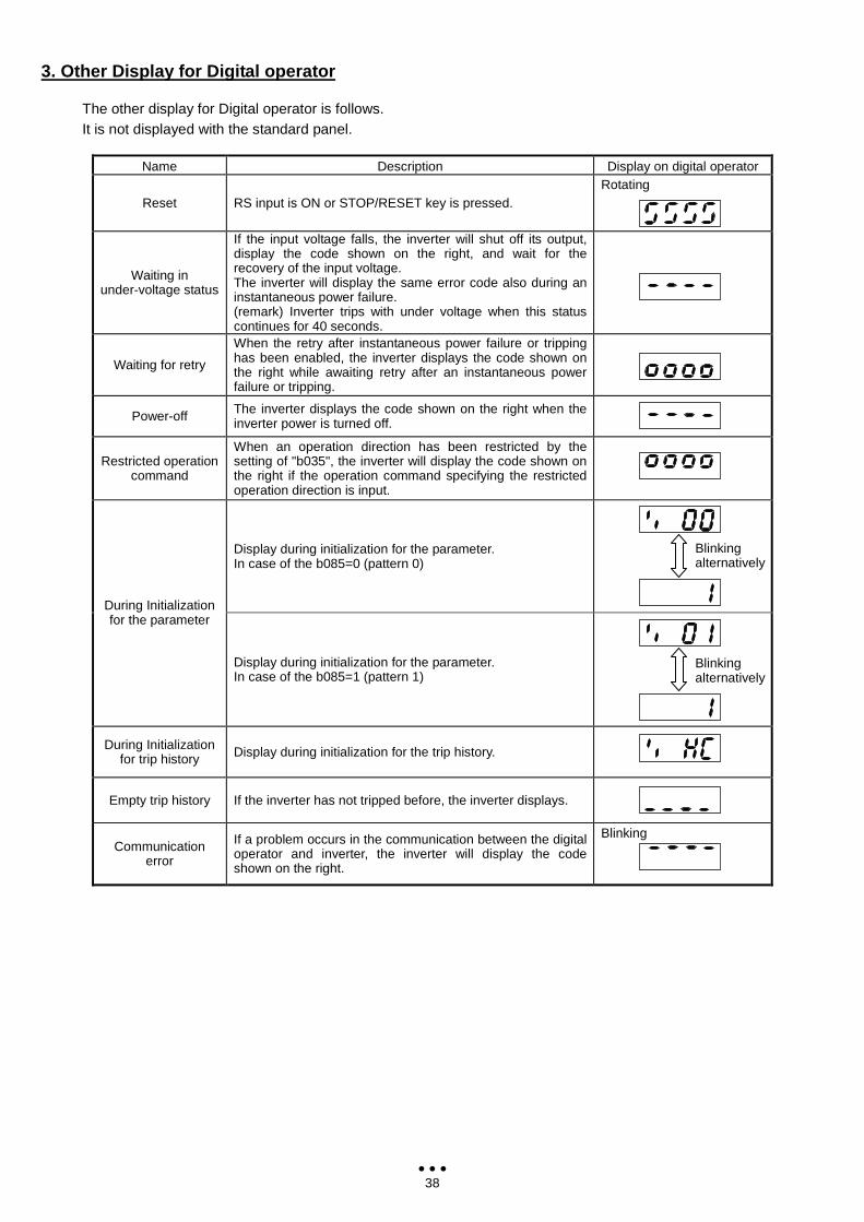
38
3. Other Display for Digital operator
The other display for Digital operator is follows. It is not displayed with the standard panel.
Name Description Display on digital operator
Reset RS input is ON or STOP/RESET key is pressed. Rotating
Waiting in under-voltage status
If the input voltage falls, the inverter will shut off its output, display the code shown on the right, and wait for the recovery of the input voltage. The inverter will display the same error code also during an instantaneous power failure. (remark) Inverter trips with under voltage when this status continues for 40 seconds.
Waiting for retry
When the retry after instantaneous power failure or tripping has been enabled, the inverter displays the code shown on the right while awaiting retry after an instantaneous power failure or tripping.
Power-off The inverter displays the code shown on the right when the inverter power is turned off.
Restricted operation command
When an operation direction has been restricted by the setting of "b035", the inverter will display the code shown on the right if the operation command specifying the restricted operation direction is input.
Display during initialization for the parameter. In case of the b085=0 (pattern 0)
During Initialization for the parameter
Display during initialization for the parameter. In case of the b085=1 (pattern 1)
During Initialization for trip history Display during initialization for the trip history.
Empty trip history If the inverter has not tripped before, the inverter displays.
Communication error
If a problem occurs in the communication between the digital operator and inverter, the inverter will display the code shown on the right.
Blinking
Blinking alternatively
Blinking alternatively

![HITACHI CAPITAL CORPORATION HITACHI … the purposes of Directive 2004/39/EC ... HITACHI CAPITAL CORPORATION HITACHI CAPITAL (UK) PLC HITACHI CAPITAL AMERICA CORP. [[] []](https://img.pdfslide.us/doc/110x75/5ad063b27f8b9a1d328e3da3/hitachi-capital-corporation-hitachi-the-purposes-of-directive-200439ec-.jpg)