Embed Size (px)
Citation preview

Certified Ethical Hacker
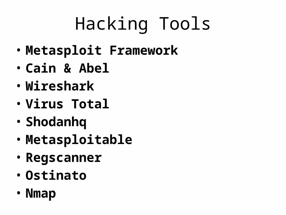
Hacking Tools• Metasploit Framework• Cain & Abel• Wireshark• Virus Total• Shodanhq• Metasploitable• Regscanner• Ostinato• Nmap
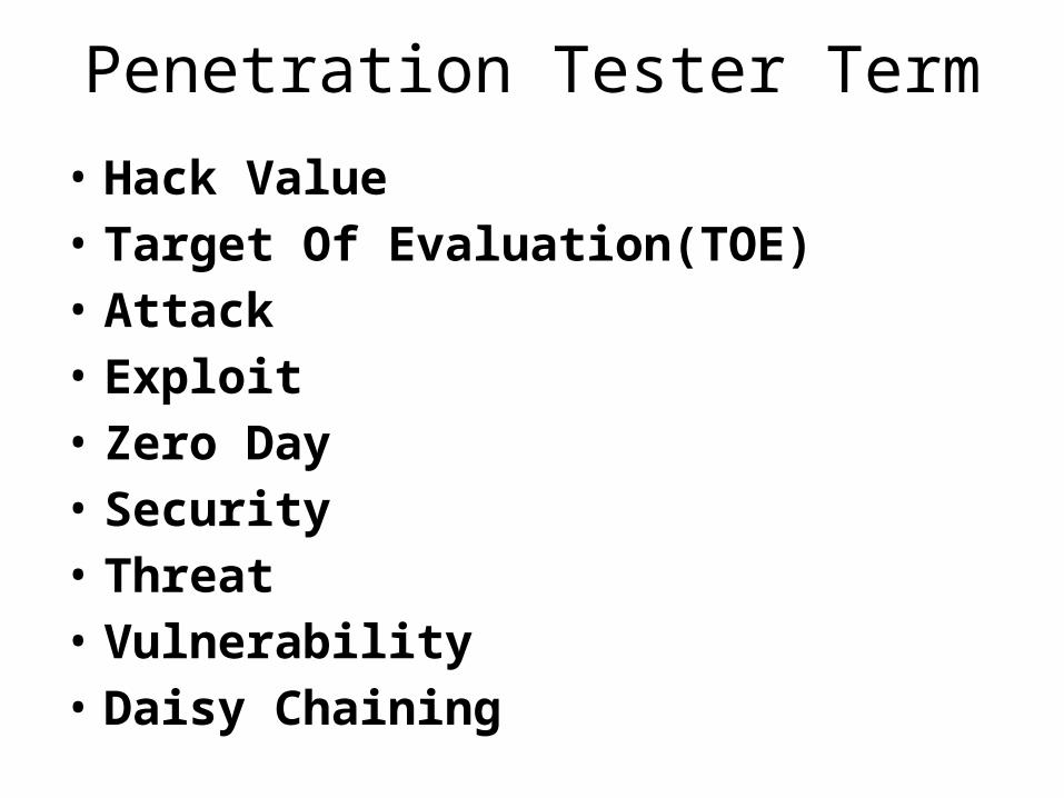
Penetration Tester Term
• Hack Value• Target Of Evaluation(TOE)• Attack• Exploit• Zero Day• Security• Threat • Vulnerability• Daisy Chaining

Types Of Pen Test
Type Knowledge
Black Box None
Grey Box Limited
White Box Full
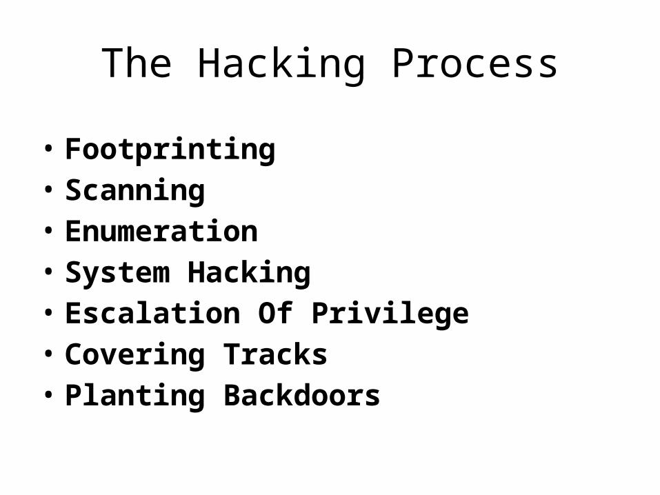
The Hacking Process
• Footprinting• Scanning• Enumeration• System Hacking• Escalation Of Privilege• Covering Tracks• Planting Backdoors
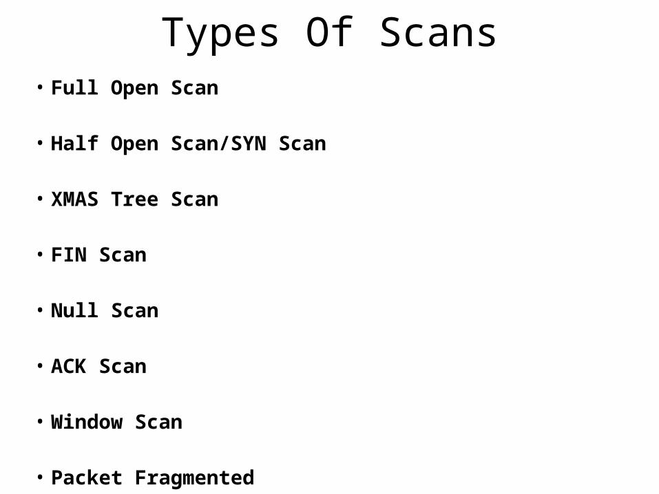
Types Of Scans• Full Open Scan
• Half Open Scan/SYN Scan
• XMAS Tree Scan
• FIN Scan
• Null Scan
• ACK Scan
• Window Scan
• Packet Fragmented
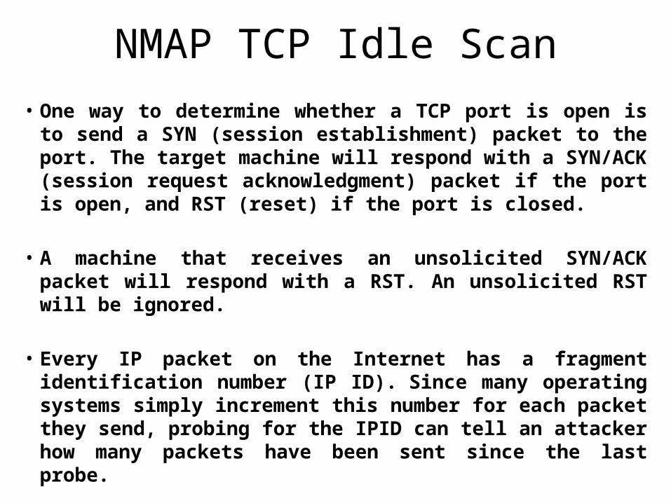
NMAP TCP Idle Scan• One way to determine whether a TCP port is open is to
send a SYN (session establishment) packet to the port. The target machine will respond with a SYN/ACK (session request acknowledgment) packet if the port is open, and RST (reset) if the port is closed.
• A machine that receives an unsolicited SYN/ACK packet will respond with a RST. An unsolicited RST will be ignored.
• Every IP packet on the Internet has a fragment identification number (IP ID). Since many operating systems simply increment this number for each packet they send, probing for the IPID can tell an attacker how many packets have been sent since the last probe.
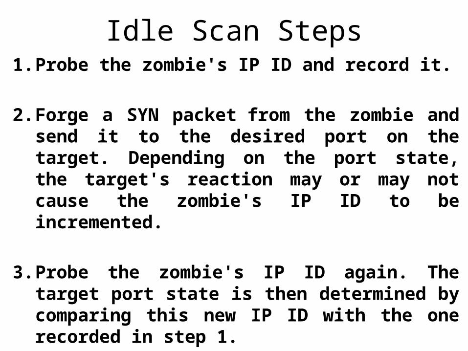
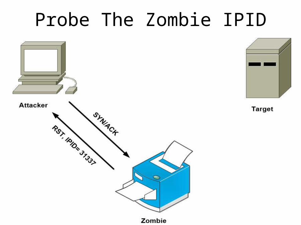
Idle Scan Steps1. Probe the zombie's IP ID and record it.
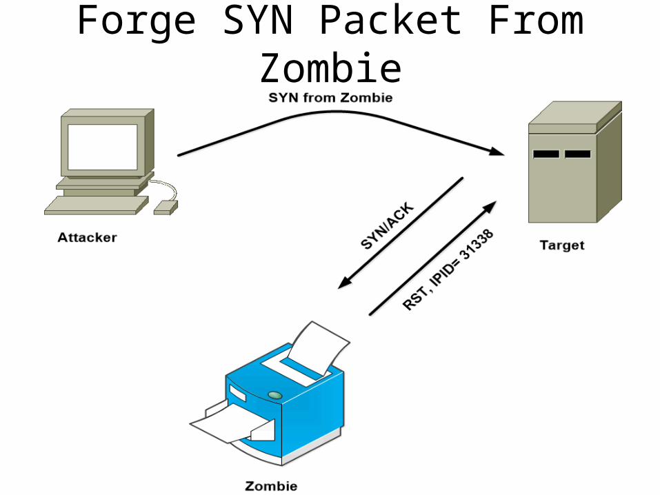
2. Forge a SYN packet from the zombie and send it to the desired port on the target. Depending on the port state, the target's reaction may or may not cause the zombie's IP ID to be incremented.
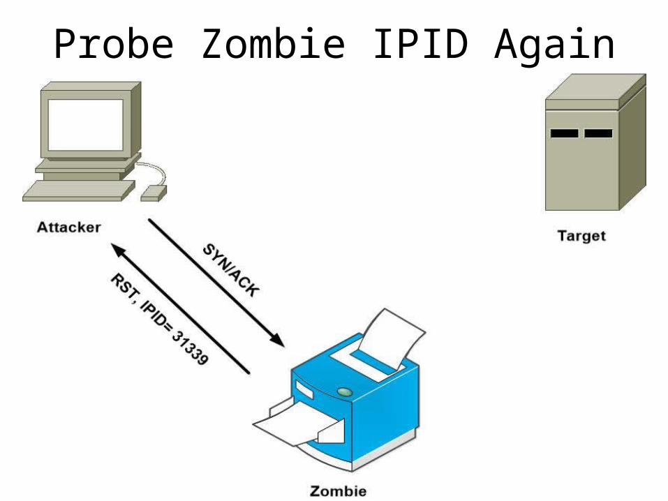
3. Probe the zombie's IP ID again. The target port state is then determined by comparing this new IP ID with the one recorded in step 1.
Probe The Zombie IPID
Forge SYN Packet From Zombie
Probe Zombie IPID Again
Good Zombie Host• It needs to assign IP ID packets incrementally
on a global (rather than per-host it communicates with) basis.
• It should be idle (hence the scan name), as extraneous traffic will bump up its IP ID sequence, confusing the scan logic.
• The lower the latency between the attacker and the zombie, and between the zombie and the target, the faster the scan will proceed.
Executing Idle Scan
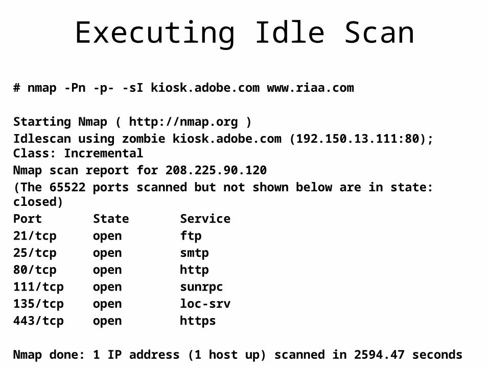
# nmap -Pn -p- -sI kiosk.adobe.com www.riaa.com
Starting Nmap ( http://nmap.org )Idlescan using zombie kiosk.adobe.com (192.150.13.111:80); Class: IncrementalNmap scan report for 208.225.90.120(The 65522 ports scanned but not shown below are in state: closed)Port State Service21/tcp open ftp25/tcp open smtp80/tcp open http111/tcp open sunrpc135/tcp open loc-srv443/tcp open https
Nmap done: 1 IP address (1 host up) scanned in 2594.47 seconds
Idle Scan Algorithm• Nmap can scan groups of up to 100 ports in parallel.
• If Nmap probes a group then finds that the zombie IP ID has increased <N> times, there must be <N> open ports among that group.
• Nmap then finds the open ports with a binary search. It splits the group into two and separately sends probes to each. If a subgroup shows zero open ports, that group's ports are all marked closed|filtered.
• If a subgroup shows one or more open ports, it is divided again and the process continues until those ports are identified.
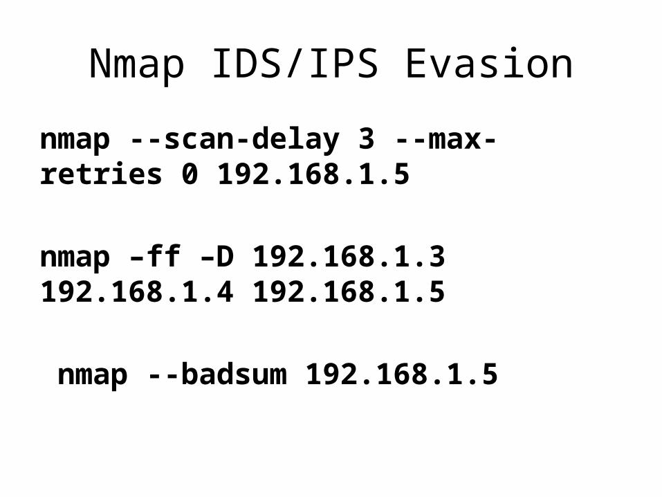
Nmap IDS/IPS Evasion
nmap --scan-delay 3 --max-retries 0 192.168.1.5
nmap –ff –D 192.168.1.3 192.168.1.4 192.168.1.5
nmap --badsum 192.168.1.5
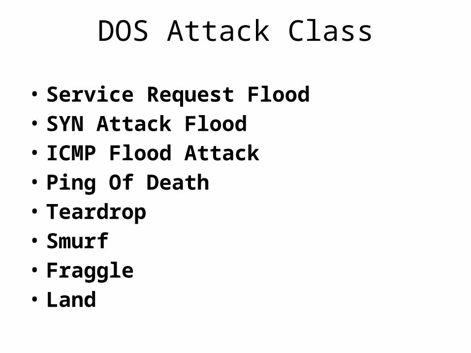
DOS Attack Class
• Service Request Flood• SYN Attack Flood• ICMP Flood Attack• Ping Of Death• Teardrop• Smurf• Fraggle• Land
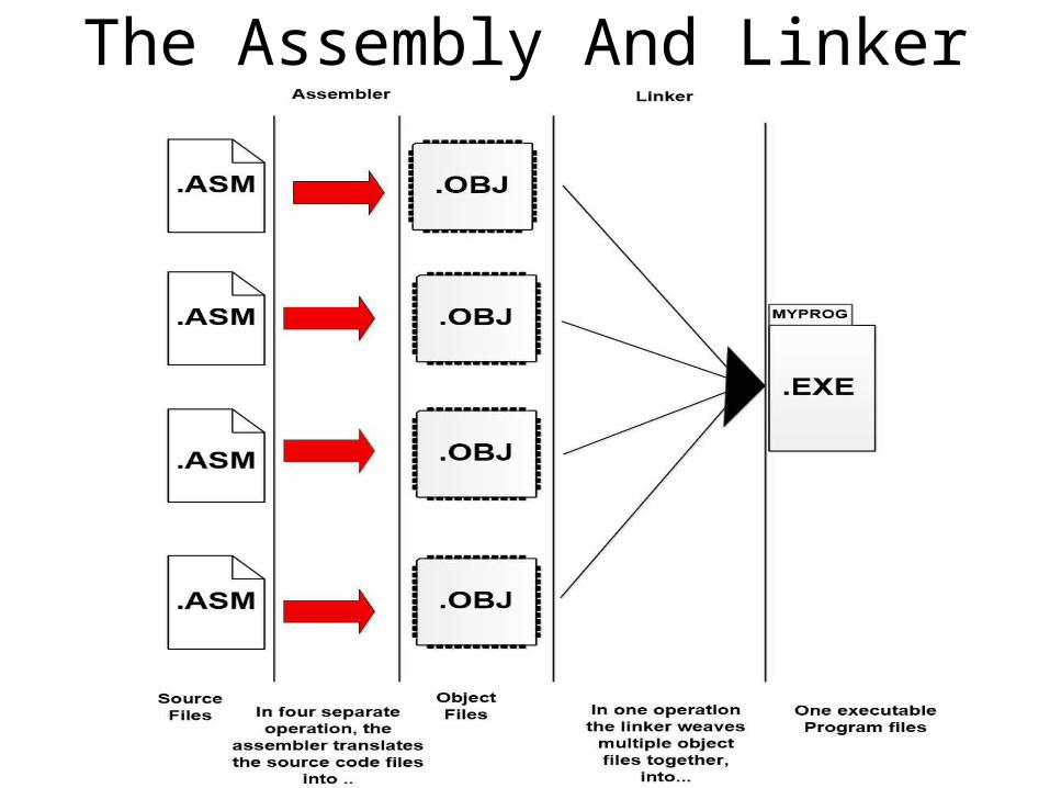
The Assembly And Linker
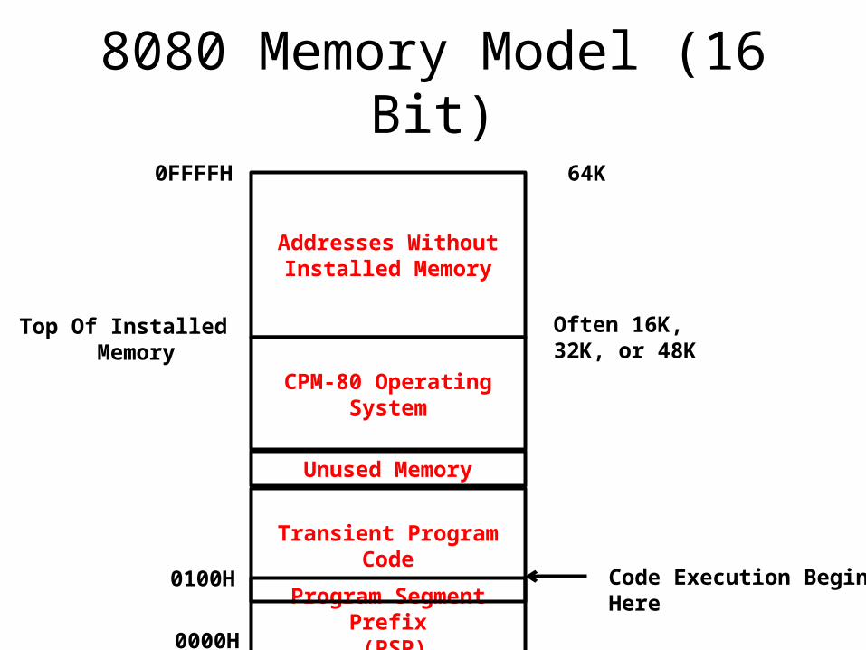
8080 Memory Model (16 Bit)
Program Segment Prefix (PSP)
Transient Program Code
Unused Memory
CPM-80 OperatingSystem
Addresses Without Installed Memory
0000H
0100H Code Execution BeginHere
Top Of Installed Memory
Often 16K, 32K, or 48K
64K0FFFFH
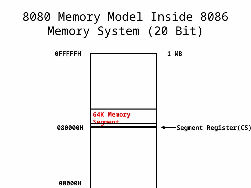
8080 Memory Model Inside 8086 Memory System (20 Bit)
64K Memory Segment
00000H
080000H
0FFFFFH
Segment Register(CS)
1 MB
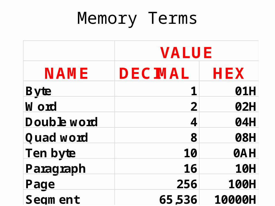
Memory Terms
NAME DECIMAL HEXByte 1 01HWord 2 02HDouble word 4 04HQuad word 8 08HTen byte 10 0AHParagraph 16 10HPage 256 100HSegment 65,536 10000H
VALUE
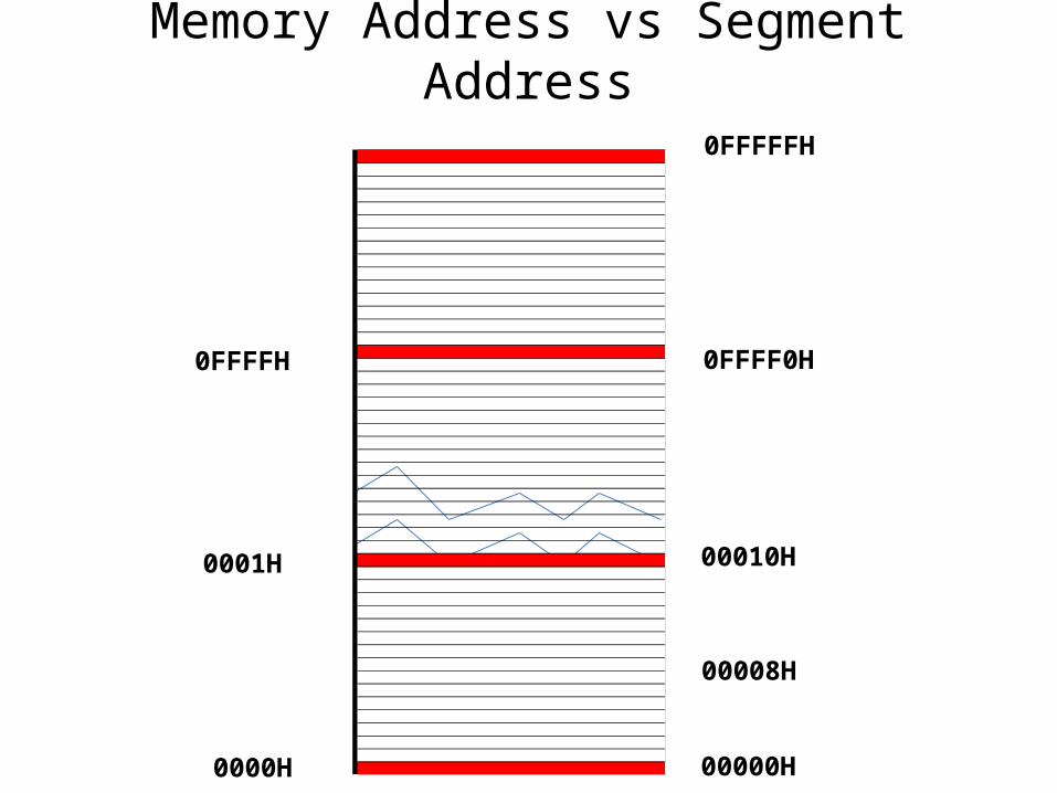
Memory Address vs Segment Address
0000H
0001H
0FFFFH 0FFFF0H
00010H
00008H
0FFFFFH
00000H
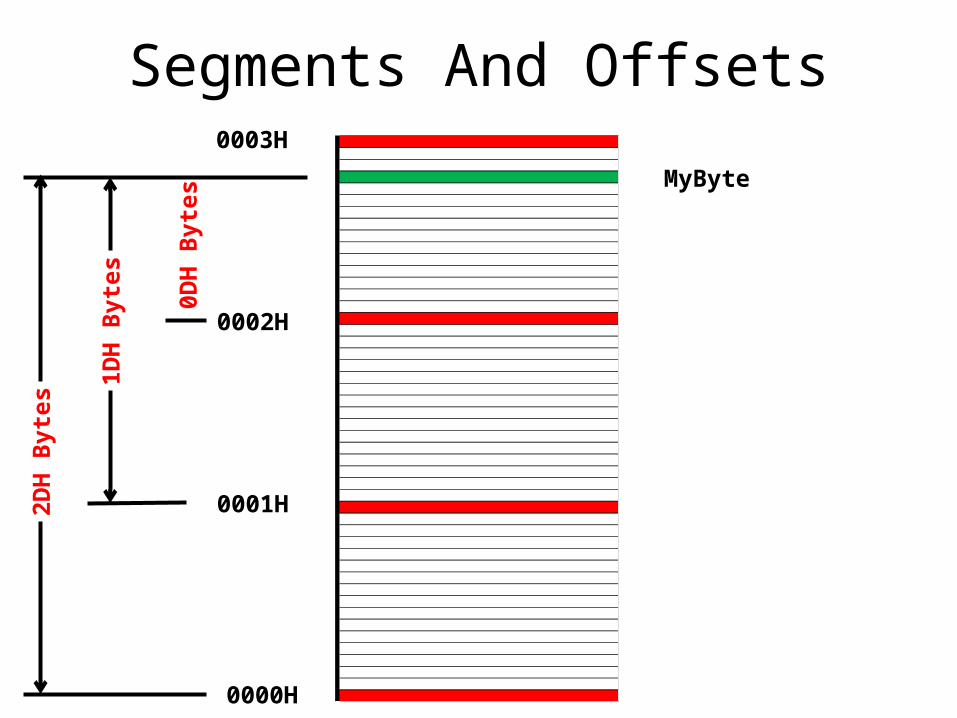
Segments And Offsets
0000H
0001H
0002H
0003H
MyByte0D
H B
ytes
1DH
Byt
es
2DH
Byt
es
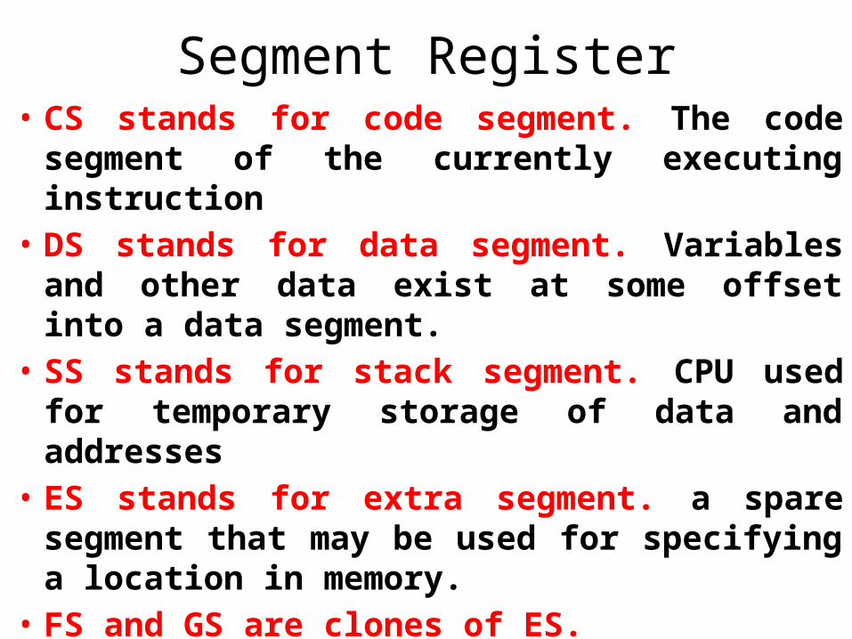
Segment Register• CS stands for code segment. The code
segment of the currently executing instruction
• DS stands for data segment. Variables and other data exist at some offset into a data segment.
• SS stands for stack segment. CPU used for temporary storage of data and addresses
• ES stands for extra segment. a spare segment that may be used for specifying a location in memory.
• FS and GS are clones of ES.
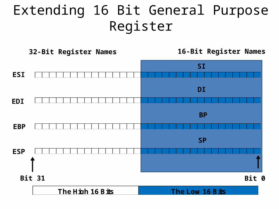
Extending 16 Bit General Purpose Register
ESISI
EBP
ESP
16-Bit Register Names32-Bit Register Names
EDI
DI
BP
SP
The High 16 Bits The Low 16 Bits
Bit 31 Bit 0
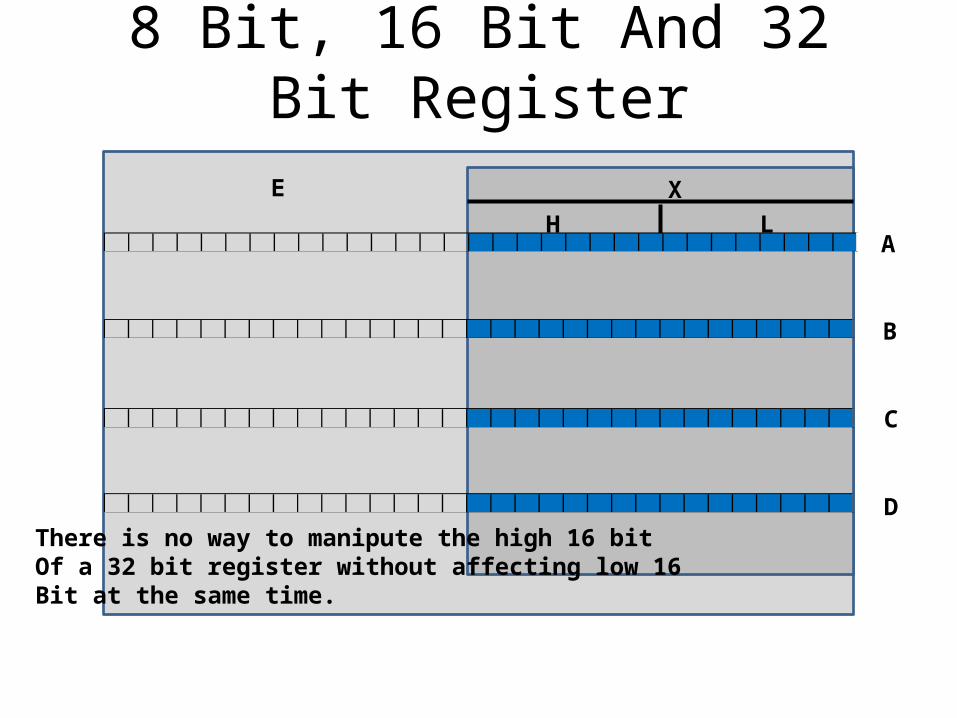
8 Bit, 16 Bit And 32 Bit Register
E X
H LA
B
C
DThere is no way to manipute the high 16 bitOf a 32 bit register without affecting low 16Bit at the same time.
Instruction Pointer• It contains the offset address of the next machine
instruction to be executed in the current code segment.
• Each time an instruction is executed, IP is incremented by some number of bytes.
• The number of bytes is the size of the instruction just executed.
• Instructions come in different sizes, ranging typically from 1 to 6 bytes.
• Together, CS and IP contain the full address of the next machine instruction to be executed.
Flags Register
• Most of the bits in the flags register are single-bit registers called flags.
• Flags has a name, such as CF, DF, OF, and so on, and each has a very specific meaning within the CPU.
• Since a single bit may contain one of only two values, 1 or 0, a test in assembly language is truly a two-way affair
Three Major Assembly Programming Models
• Real Mode Flat Models.
• Real Mode Segmented Models.
• Protected Mode Flat Models
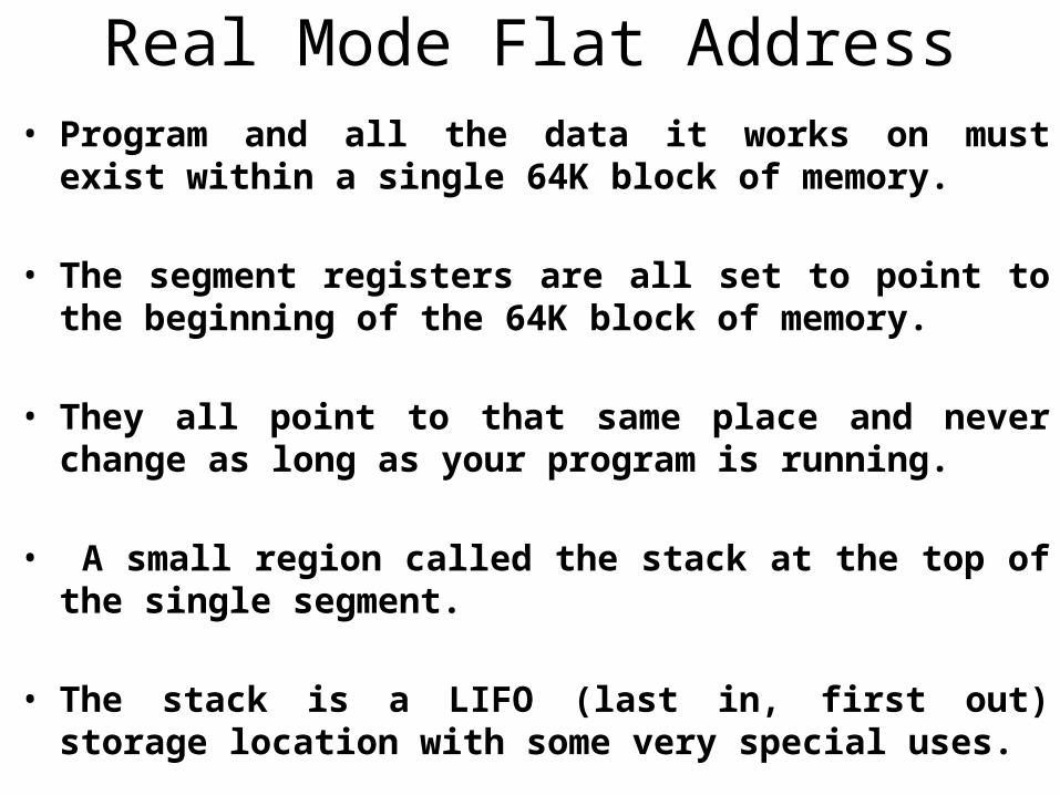
Real Mode Flat Address• Program and all the data it works on must exist within a
single 64K block of memory.
• The segment registers are all set to point to the beginning of the 64K block of memory.
• They all point to that same place and never change as long as your program is running.
• A small region called the stack at the top of the single segment.
• The stack is a LIFO (last in, first out) storage location with some very special uses.
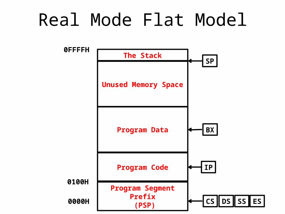
Real Mode Flat Model
Program Segment Prefix (PSP)
Program Code
Program Data
Unused Memory Space
The Stack
0000H
0100H
0FFFFH
CS
IP
SS ESDS
BX
SP
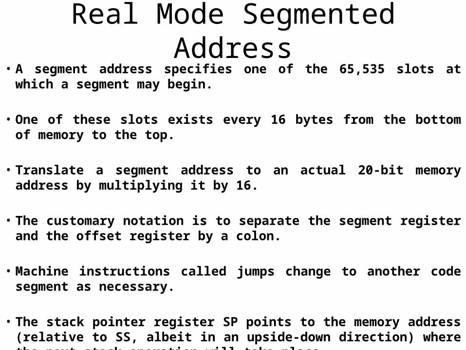
Real Mode Segmented Address• A segment address specifies one of the 65,535 slots at which a
segment may begin.
• One of these slots exists every 16 bytes from the bottom of memory to the top.
• Translate a segment address to an actual 20-bit memory address by multiplying it by 16.
• The customary notation is to separate the segment register and the offset register by a colon.
• Machine instructions called jumps change to another code segment as necessary.
• The stack pointer register SP points to the memory address (relative to SS, albeit in an upside-down direction) where the next stack operation will take place.
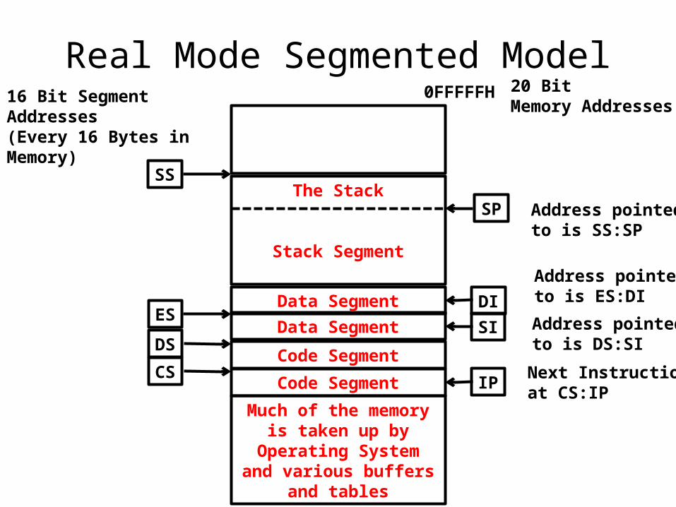
Real Mode Segmented Model
Much of the memory is taken up by Operating
System and various buffers and tables
Code Segment
Data Segment
The Stack
Stack Segment
Code Segment
Data Segment
CSIP
SS
ES
DS
SP
SI
DI
16 Bit Segment Addresses(Every 16 Bytes in Memory)
20 Bit Memory Addresses
0FFFFFH
Address pointed to is SS:SP
Address pointed to is ES:DI
Address pointed to is DS:SI
Next Instruction isat CS:IP
Protected Mode Flat Address• Console applications use protected mode flat model
and are fairly straightforward compared to writing Windows applications.
• The segment registers are now to be considered part of the operating system and most cases can neither read nor change them directly.
• Rules to view certain parts of memory space is depend on OS.
• What difficulty exists in programming for protected mode flat model lies in understanding the operating system, its requirements, and its restrictions.
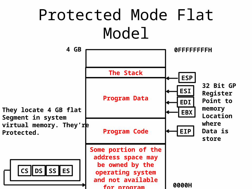
Protected Mode Flat Model
Some portion of the address space may be
owned by the operating system and not available
for program
Program Code
Program Data
The Stack
CS SS ESDS
0000H
EIP
EDI
EBX
ESI
ESP32 Bit GP RegisterPoint to memoryLocation whereData is store
They locate 4 GB flat Segment in system virtual memory. They’reProtected.
0FFFFFFFFH4 GB
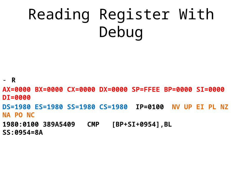
Reading Register With Debug
- R
AX=0000 BX=0000 CX=0000 DX=0000 SP=FFEE BP=0000 SI=0000 DI=0000
DS=1980 ES=1980 SS=1980 CS=1980 IP=0100 NV UP EI PL NZ NA PO NC
1980:0100 389A5409 CMP [BP+SI+0954],BL SS:0954=8A
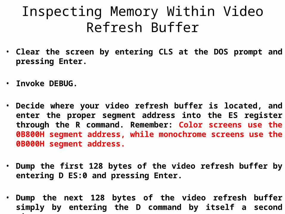
Inspecting Memory Within Video Refresh Buffer
• Clear the screen by entering CLS at the DOS prompt and pressing Enter.
• Invoke DEBUG.
• Decide where your video refresh buffer is located, and enter the proper segment address into the ES register through the R command. Remember: Color screens use the 0B800H segment address, while monochrome screens use the 0B000H segment address.
• Dump the first 128 bytes of the video refresh buffer by entering D ES:0 and pressing Enter.
• Dump the next 128 bytes of the video refresh buffer simply by entering the D command by itself a second time.
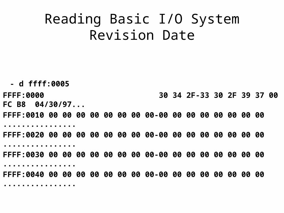
Reading Basic I/O System Revision Date
- d ffff:0005
FFFF:0000 30 34 2F-33 30 2F 39 37 00 FC B8 04/30/97...
FFFF:0010 00 00 00 00 00 00 00 00-00 00 00 00 00 00 00 00 ................
FFFF:0020 00 00 00 00 00 00 00 00-00 00 00 00 00 00 00 00 ................
FFFF:0030 00 00 00 00 00 00 00 00-00 00 00 00 00 00 00 00 ................
FFFF:0040 00 00 00 00 00 00 00 00-00 00 00 00 00 00 00 00 ................

Common Debug Command
• A command (for Assemble)
DEBUG responds by displaying the current value of CS:IP and then waits for you to enter an assembly language instruction.
• G command (for Go)
Executes programs in memory starting at CS:IP
• T command(for Trace)
Trace executes the single instruction at CS:IP.
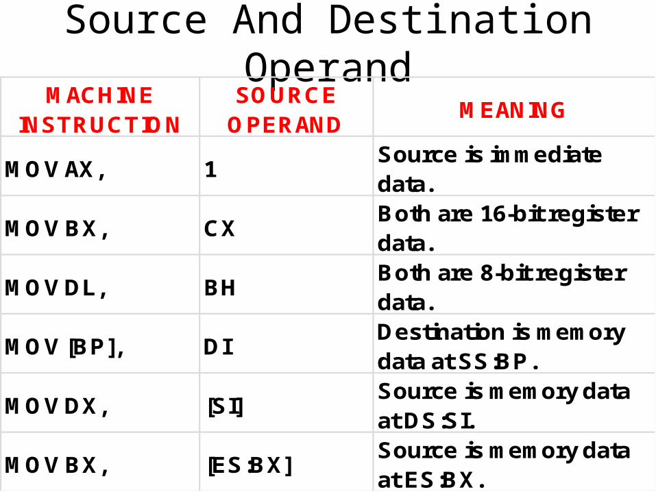
Source And Destination OperandMACHINE
INSTRUCTIONSOURCE
OPERANDMEANING
MOV AX, 1Source is immediate data.
MOV BX, CX Both are 16-bit register data.
MOV DL, BHBoth are 8-bit register data.
MOV [BP], DIDestination is memory data at SS:BP.
MOV DX, [SI]Source is memory data at DS:SI.
MOV BX, [ES:BX]Source is memory data at ES:BX.
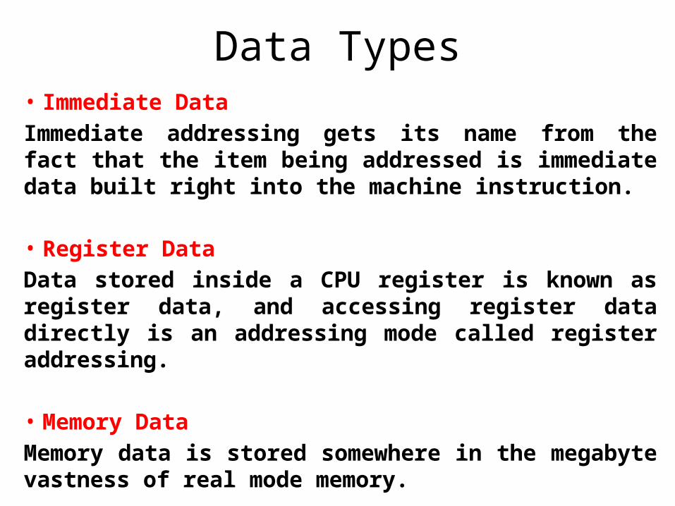
Data Types• Immediate Data
Immediate addressing gets its name from the fact that the item being addressed is immediate data built right into the machine instruction.
• Register Data
Data stored inside a CPU register is known as register data, and accessing register data directly is an addressing mode called register addressing.
• Memory Data
Memory data is stored somewhere in the megabyte vastness of real mode memory.
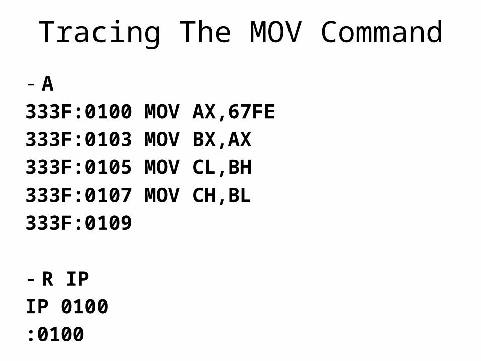
Tracing The MOV Command
- A
333F:0100 MOV AX,67FE
333F:0103 MOV BX,AX
333F:0105 MOV CL,BH
333F:0107 MOV CH,BL
333F:0109
- R IP
IP 0100
:0100
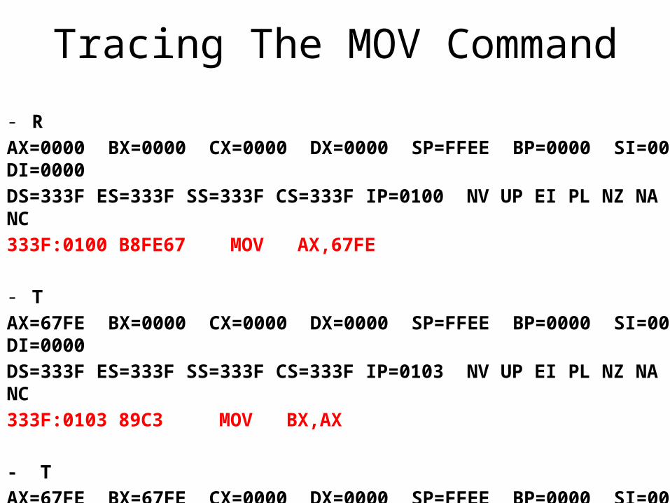
Tracing The MOV Command
- R
AX=0000 BX=0000 CX=0000 DX=0000 SP=FFEE BP=0000 SI=0000 DI=0000
DS=333F ES=333F SS=333F CS=333F IP=0100 NV UP EI PL NZ NA PO NC
333F:0100 B8FE67 MOV AX,67FE
- T
AX=67FE BX=0000 CX=0000 DX=0000 SP=FFEE BP=0000 SI=0000 DI=0000
DS=333F ES=333F SS=333F CS=333F IP=0103 NV UP EI PL NZ NA PO NC
333F:0103 89C3 MOV BX,AX
- T
AX=67FE BX=67FE CX=0000 DX=0000 SP=FFEE BP=0000 SI=0000 DI=0000
DS=333F ES=333F SS=333F CS=333F IP=0105 NV UP EI PL NZ NA PO NC
333F:0105 88F9 MOV CL,BH
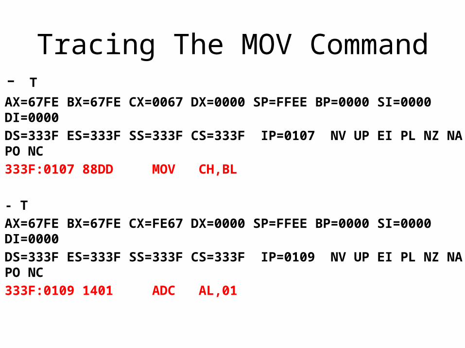
Tracing The MOV Command- TAX=67FE BX=67FE CX=0067 DX=0000 SP=FFEE BP=0000 SI=0000 DI=0000
DS=333F ES=333F SS=333F CS=333F IP=0107 NV UP EI PL NZ NA PO NC
333F:0107 88DD MOV CH,BL
- T
AX=67FE BX=67FE CX=FE67 DX=0000 SP=FFEE BP=0000 SI=0000 DI=0000
DS=333F ES=333F SS=333F CS=333F IP=0109 NV UP EI PL NZ NA PO NC
333F:0109 1401 ADC AL,01
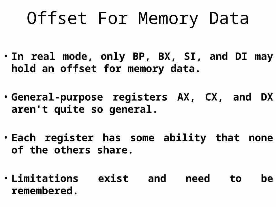
Offset For Memory Data
• In real mode, only BP, BX, SI, and DI may hold an offset for memory data.
• General-purpose registers AX, CX, and DX aren't quite so general.
• Each register has some ability that none of the others share.
• Limitations exist and need to be remembered.
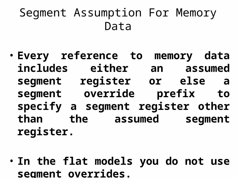
Segment Assumption For Memory Data
• Every reference to memory data includes either an assumed segment register or else a segment override prefix to specify a segment register other than the assumed segment register.
• In the flat models you do not use segment overrides.
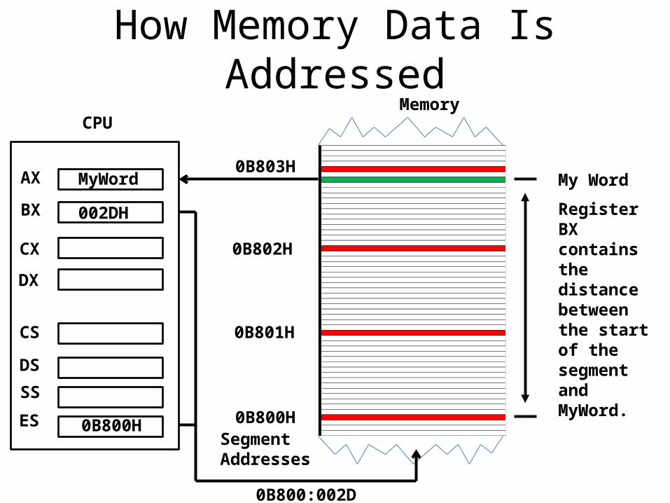
How Memory Data Is Addressed
Segment Addresses
0B800H
0B801H
0B802H
0B803HMy Word
Register BX contains the distance between the start of the segment and MyWord.
002DH
MyWord
0B800H
0B800:002D
AX
SS
ES
DS
CS
BX
CX
DX
CPUMemory
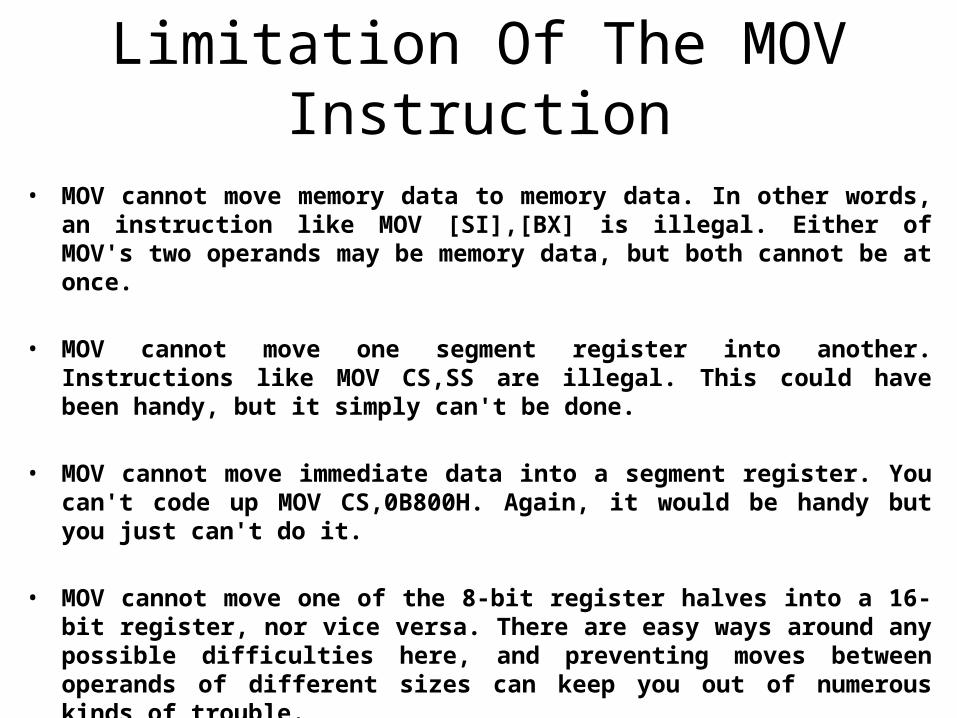
Limitation Of The MOV Instruction
• MOV cannot move memory data to memory data. In other words, an instruction like MOV [SI],[BX] is illegal. Either of MOV's two operands may be memory data, but both cannot be at once.
• MOV cannot move one segment register into another. Instructions like MOV CS,SS are illegal. This could have been handy, but it simply can't be done.
• MOV cannot move immediate data into a segment register. You can't code up MOV CS,0B800H. Again, it would be handy but you just can't do it.
• MOV cannot move one of the 8-bit register halves into a 16-bit register, nor vice versa. There are easy ways around any possible difficulties here, and preventing moves between operands of different sizes can keep you out of numerous kinds of trouble.
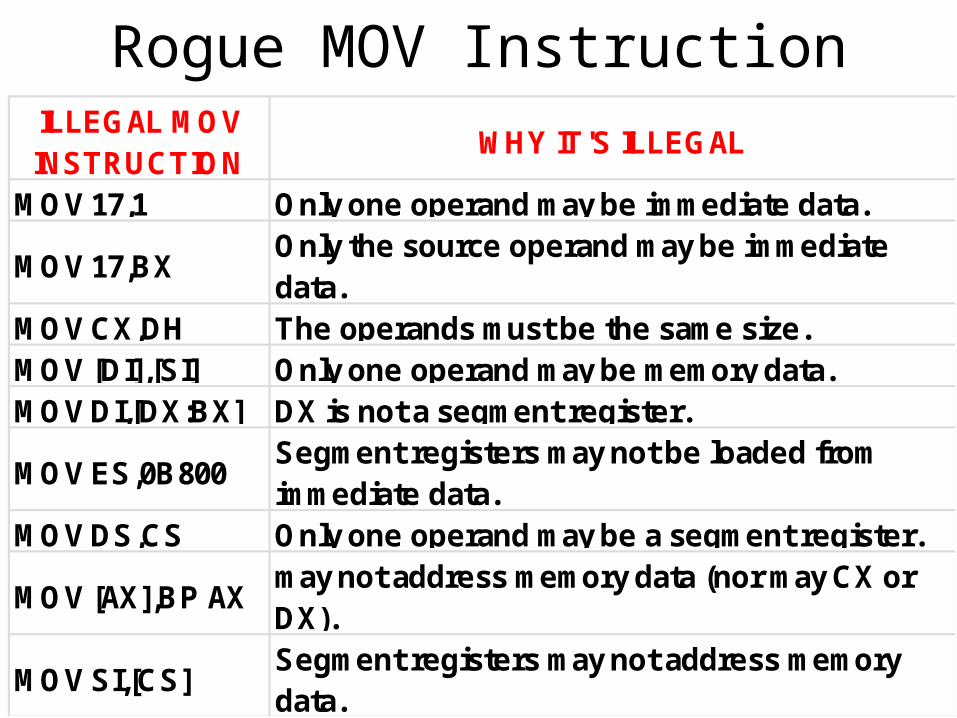
Rogue MOV InstructionILLEGAL MOV INSTRUCTION
WHY IT'S ILLEGAL
MOV 17,1 Only one operand may be immediate data.
MOV 17,BXOnly the source operand may be immediate data.
MOV CX,DH The operands must be the same size.MOV [DI],[SI] Only one operand may be memory data.MOV DI,[DX:BX] DX is not a segment register.
MOV ES,0B800Segment registers may not be loaded from immediate data.
MOV DS,CS Only one operand may be a segment register.
MOV [AX],BP AX may not address memory data (nor may CX or DX).
MOV SI,[CS] Segment registers may not address memory data.
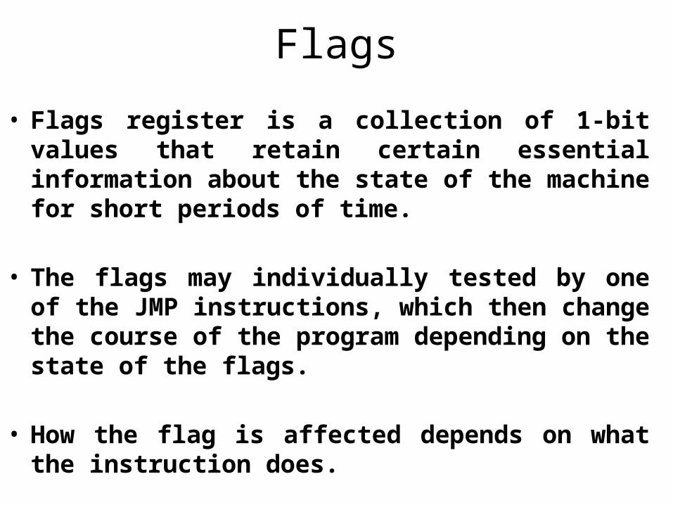
Flags
• Flags register is a collection of 1-bit values that retain certain essential information about the state of the machine for short periods of time.
• The flags may individually tested by one of the JMP instructions, which then change the course of the program depending on the state of the flags.
• How the flag is affected depends on what the instruction does.
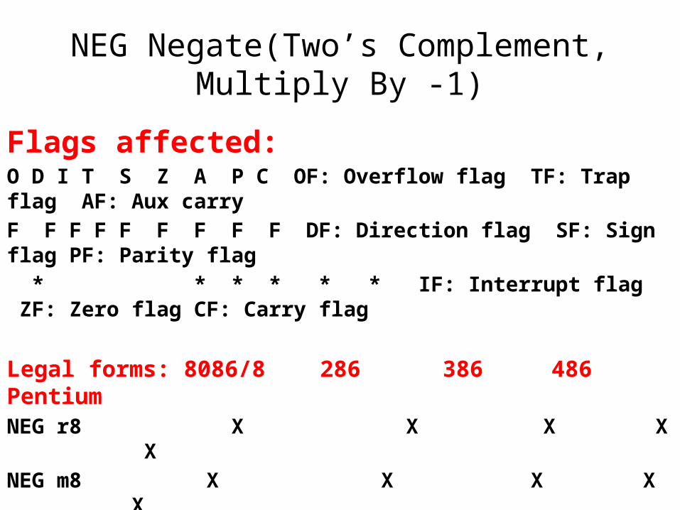
NEG Negate(Two’s Complement, Multiply By -1)
Flags affected:O D I T S Z A P C OF: Overflow flag TF: Trap flag AF: Aux carry
F F F F F F F F F DF: Direction flag SF: Sign flag PF: Parity flag
* * * * * * IF: Interrupt flag ZF: Zero flag CF: Carry flag
Legal forms: 8086/8 286 386 486 PentiumNEG r8 X X X X X
NEG m8 X X X X X
NEG r16 X X X X X
NEG m16 X X X X X
NEG r32 X X X
NEG m32 X X X
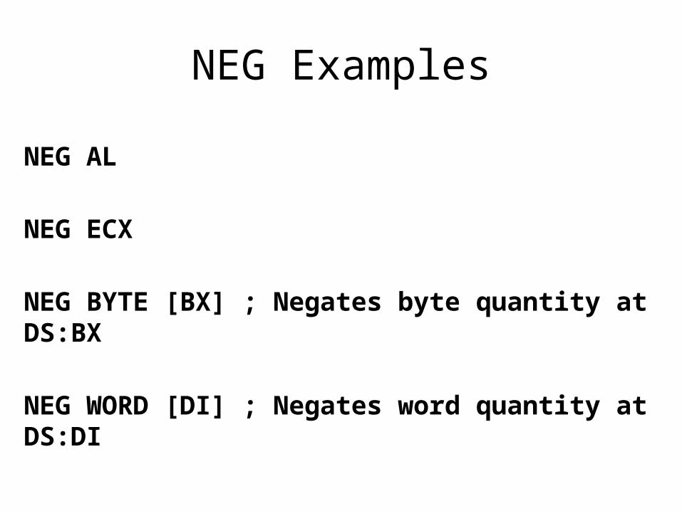
NEG Examples
NEG AL
NEG ECX
NEG BYTE [BX] ; Negates byte quantity at DS:BX
NEG WORD [DI] ; Negates word quantity at DS:DI
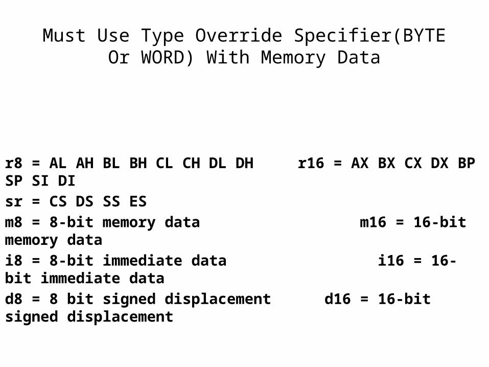
Must Use Type Override Specifier(BYTE Or WORD) With Memory Data
r8 = AL AH BL BH CL CH DL DH r16 = AX BX CX DX BP SP SI DI
sr = CS DS SS ES
m8 = 8-bit memory data m16 = 16-bit memory data
i8 = 8-bit immediate data i16 = 16-bit immediate data
d8 = 8 bit signed displacement d16 = 16-bit signed displacement
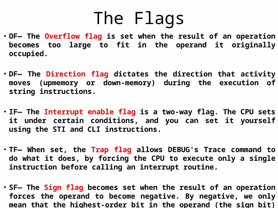
The Flags• OF— The Overflow flag is set when the result of an operation becomes
too large to fit in the operand it originally occupied.
• DF— The Direction flag dictates the direction that activity moves (upmemory or down-memory) during the execution of string instructions.
• IF— The Interrupt enable flag is a two-way flag. The CPU sets it under certain conditions, and you can set it yourself using the STI and CLI instructions.
• TF— When set, the Trap flag allows DEBUG's Trace command to do what it does, by forcing the CPU to execute only a single instruction before calling an interrupt routine.
• SF— The Sign flag becomes set when the result of an operation forces the operand to become negative. By negative, we only mean that the highest-order bit in the operand (the sign bit) becomes 1 during a signed arithmetic operation.
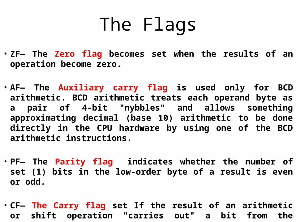
The Flags• ZF— The Zero flag becomes set when the results of an
operation become zero.
• AF— The Auxiliary carry flag is used only for BCD arithmetic. BCD arithmetic treats each operand byte as a pair of 4-bit "nybbles" and allows something approximating decimal (base 10) arithmetic to be done directly in the CPU hardware by using one of the BCD arithmetic instructions.
• PF— The Parity flag indicates whether the number of set (1) bits in the low-order byte of a result is even or odd.
• CF— The Carry flag set If the result of an arithmetic or shift operation "carries out" a bit from the operand.
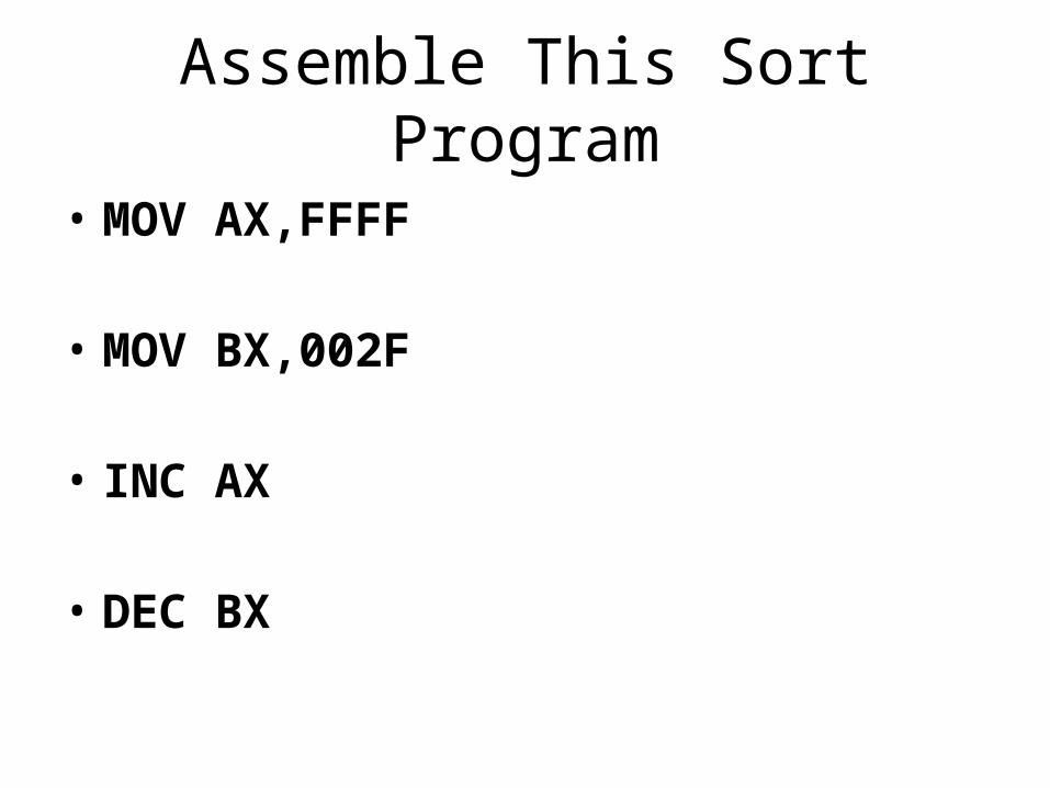
Assemble This Sort Program
• MOV AX,FFFF
• MOV BX,002F
• INC AX
• DEC BX
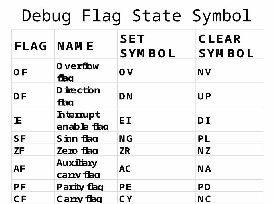
Debug Flag State Symbol
FLAG NAME SET SYMBOL
CLEAR SYMBOL
OFOverflow flag
OV NV
DFDirection flag
DN UP
IE Interrupt enable flag
EI DI
SF Sign flag NG PLZF Zero flag ZR NZ
AF Auxiliary carry flag
AC NA
PF Parity flag PE POCF Carry flag CY NC
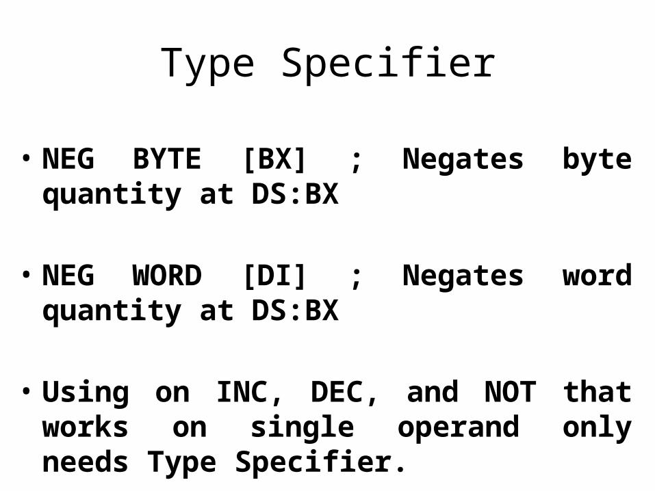
Type Specifier
• NEG BYTE [BX] ; Negates byte quantity at DS:BX
• NEG WORD [DI] ; Negates word quantity at DS:BX
• Using on INC, DEC, and NOT that works on single operand only needs Type Specifier.
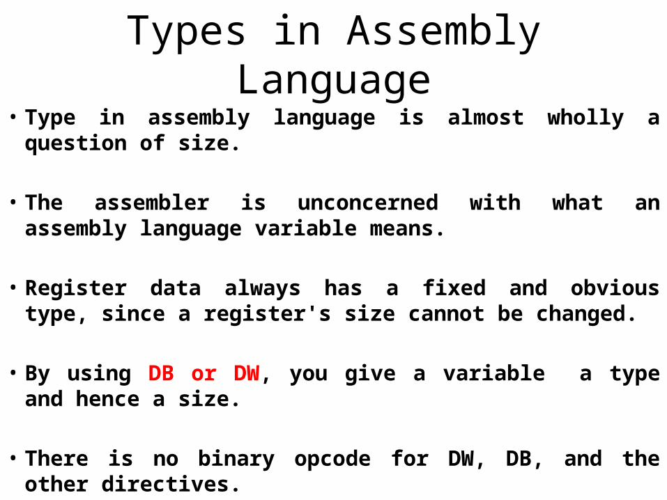
Types in Assembly Language• Type in assembly language is almost wholly a question of
size.
• The assembler is unconcerned with what an assembly language variable means.
• Register data always has a fixed and obvious type, since a register's size cannot be changed.
• By using DB or DW, you give a variable a type and hence a size.
• There is no binary opcode for DW, DB, and the other directives.
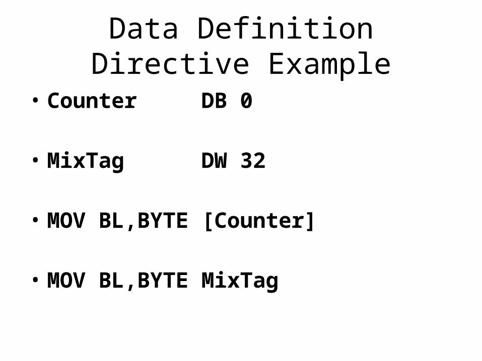
Data Definition Directive Example
• Counter DB 0
• MixTag DW 32
• MOV BL,BYTE [Counter]
• MOV BL,BYTE MixTag
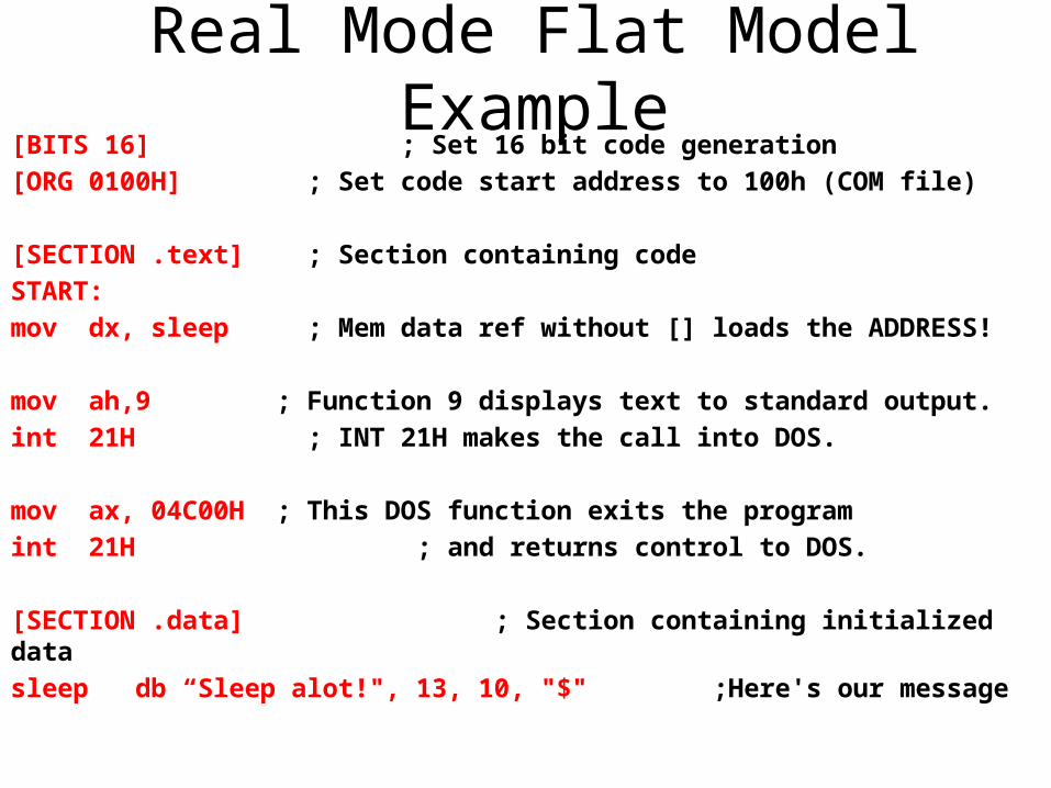
Real Mode Flat Model Example[BITS 16] ; Set 16 bit code generation [ORG 0100H] ; Set code start address to 100h (COM file)
[SECTION .text] ; Section containing code START:mov dx, sleep ; Mem data ref without [] loads the ADDRESS!
mov ah,9 ; Function 9 displays text to standard output. int 21H ; INT 21H makes the call into DOS.
mov ax, 04C00H ; This DOS function exits the program int 21H ; and returns control to DOS.
[SECTION .data] ; Section containing initialized datasleep db “Sleep alot!", 13, 10, "$" ;Here's our message
Valid Labels
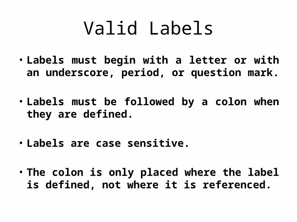
• Labels must begin with a letter or with an underscore, period, or question mark.
• Labels must be followed by a colon when they are defined.
• Labels are case sensitive.
• The colon is only placed where the label is defined, not where it is referenced.
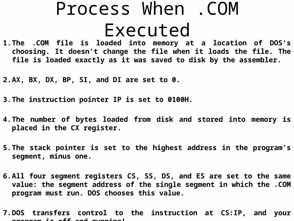
Process When .COM Executed1. The .COM file is loaded into memory at a location of DOS's choosing. It
doesn't change the file when it loads the file. The file is loaded exactly as it was saved to disk by the assembler.
2. AX, BX, DX, BP, SI, and DI are set to 0.
3. The instruction pointer IP is set to 0100H.
4. The number of bytes loaded from disk and stored into memory is placed in the CX register.
5. The stack pointer is set to the highest address in the program's segment, minus one.
6. All four segment registers CS, SS, DS, and ES are set to the same value: the segment address of the single segment in which the .COM program must run. DOS chooses this value.
7. DOS transfers control to the instruction at CS:IP, and your program is off and running!
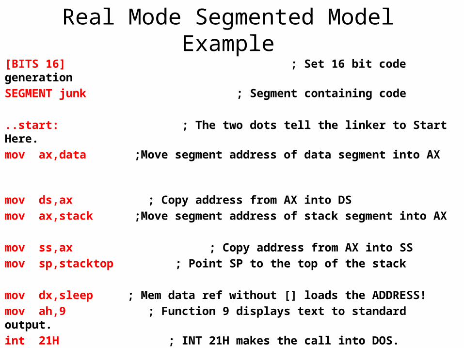
Real Mode Segmented Model Example[BITS 16] ; Set 16 bit code generation
SEGMENT junk ; Segment containing code
..start: ; The two dots tell the linker to Start Here.
mov ax,data ;Move segment address of data segment into AX
mov ds,ax ; Copy address from AX into DS
mov ax,stack ;Move segment address of stack segment into AX
mov ss,ax ; Copy address from AX into SS
mov sp,stacktop ; Point SP to the top of the stack
mov dx,sleep ; Mem data ref without [] loads the ADDRESS!
mov ah,9 ; Function 9 displays text to standard output.
int 21H ; INT 21H makes the call into DOS.
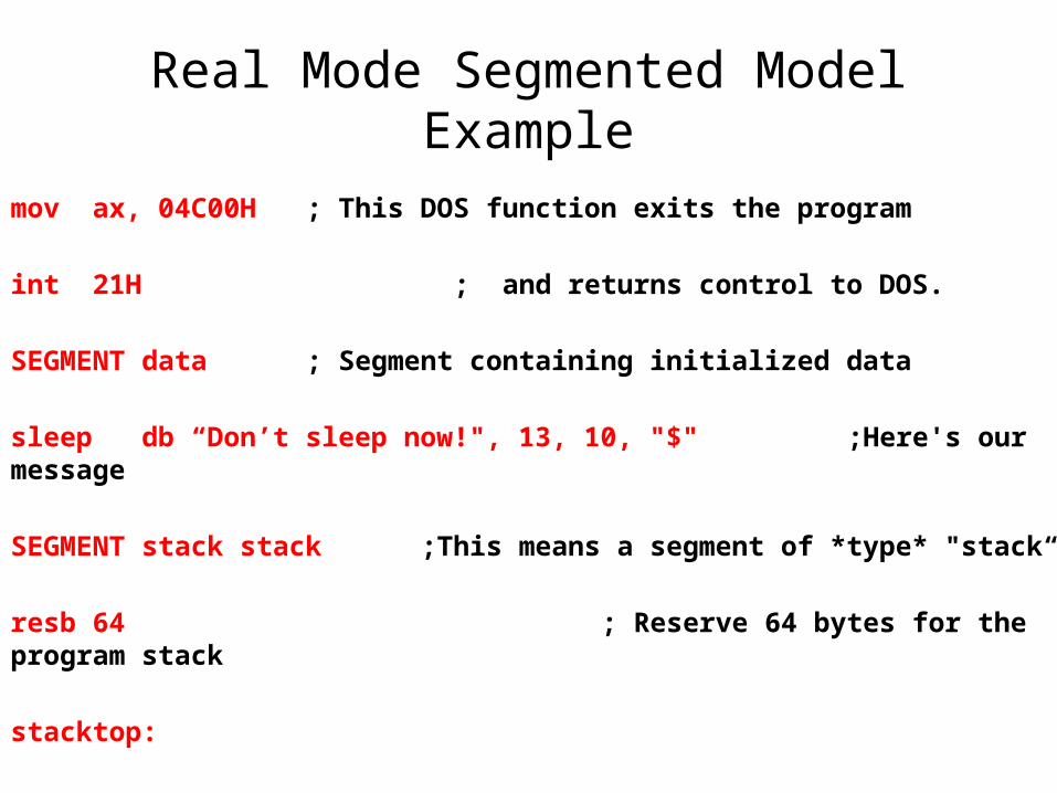
Real Mode Segmented Model Example
mov ax, 04C00H ; This DOS function exits the program
int 21H ; and returns control to DOS.
SEGMENT data ; Segment containing initialized data
sleep db “Don’t sleep now!", 13, 10, "$" ;Here's our message
SEGMENT stack stack ;This means a segment of *type* "stack“
resb 64 ; Reserve 64 bytes for the program stack
stacktop:
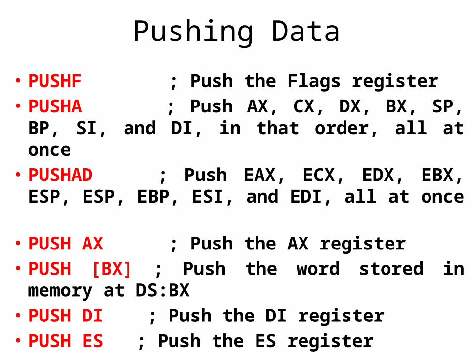
Pushing Data
• PUSHF ; Push the Flags register • PUSHA ; Push AX, CX, DX, BX, SP, BP,
SI, and DI, in that order, all at once • PUSHAD ; Push EAX, ECX, EDX, EBX,
ESP, ESP, EBP, ESI, and EDI, all at once • PUSH AX ; Push the AX register • PUSH [BX] ; Push the word stored in
memory at DS:BX • PUSH DI ; Push the DI register • PUSH ES ; Push the ES register
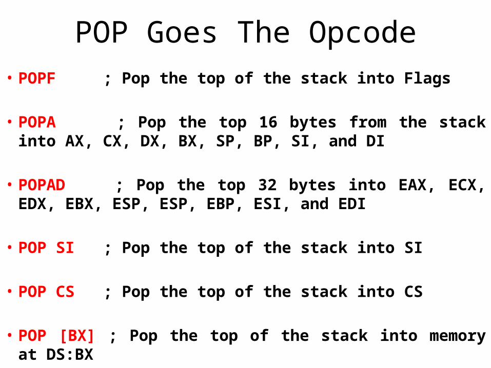
POP Goes The Opcode• POPF ; Pop the top of the stack into Flags
• POPA ; Pop the top 16 bytes from the stack into AX, CX, DX, BX, SP, BP, SI, and DI
• POPAD ; Pop the top 32 bytes into EAX, ECX, EDX, EBX, ESP, ESP, EBP, ESI, and EDI
• POP SI ; Pop the top of the stack into SI
• POP CS ; Pop the top of the stack into CS
• POP [BX] ; Pop the top of the stack into memory at DS:BX
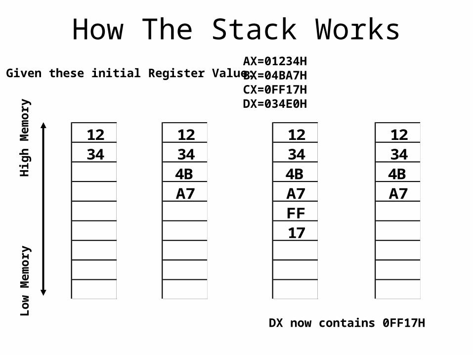
How The Stack Works
1234
12344BA7
12344BA7FF17
12344BA7
Given these initial Register Value: AX=01234HBX=04BA7HCX=0FF17HDX=034E0H
Lo
w M
emo
ryH
igh
Mem
ory
DX now contains 0FF17H
Storage For The Short Term• Unless the stack is empty, SP points to real data,
not empty space.
• Stack crashes are serious business, at least in part because there is only one stack in action at a time in real mode.
• The stack should be considered a place to stash things for the short term.
• One excellent use of the stack allows the all-too-few registers to do multiple duty
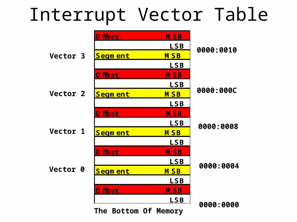
Interrupt Vector TableOffset MSB LSBSegment MSB LSBOffset MSB LSBSegment MSB LSBOffset MSB LSBSegment MSB LSBOffset MSB LSBSegment MSB LSBOffset MSB LSB
Vector 0
Vector 1
Vector 2
Vector 3
0000:0004
0000:0000
0000:0008
0000:000C
0000:0010
The Bottom Of Memory
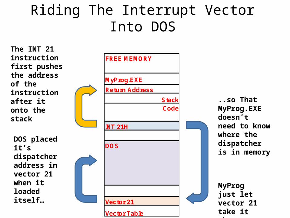
Riding The Interrupt Vector Into DOS
FREE MEMORY
MyProg.EXE
Return Address
StackCode
INT 21H
DOS
Vector 21
Vector Table
Dispatcher
..so That MyProg.EXE doesn’t need to know where thedispatcher is in memory
MyProg just let vector 21 take it there
DOS placed it’s dispatcher address in vector 21 when it loaded itself…
The INT 21 instruction first pushes the address of the instruction after it onto the stack
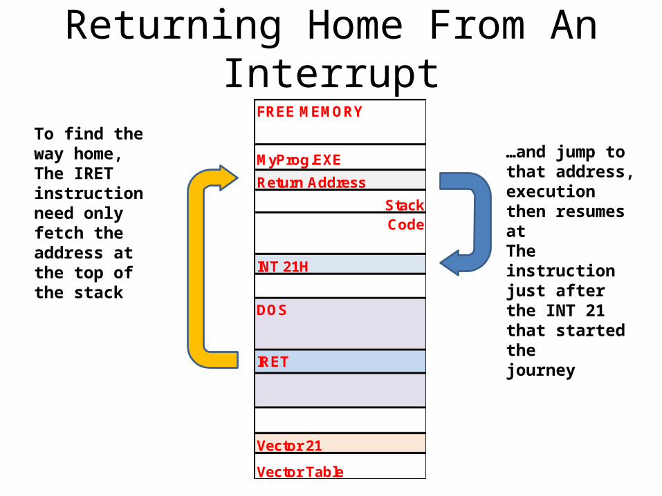
Returning Home From An InterruptFREE MEMORY
MyProg.EXE
Return Address
StackCode
INT 21H
DOS
IRET
Vector 21
Vector Table
Dispatcher
To find the way home,The IRET instruction need only fetch the address at the top of the stack
…and jump to that address, execution then resumes atThe instruction just after the INT 21 that started thejourney
Software Interrupts Vs Hardware Interrupts
• Software interrupt triggering event is part of the software. That is, an INT instruction.
• Hardware interrupt, the triggering event is an electrical signal applied to the CPU chip itself without any INT instruction taking a hand in the process.
• If the interrupt signal came from a serial port board, the CPU would then allow the serial port board to transfer a character byte from itself into the CPU.
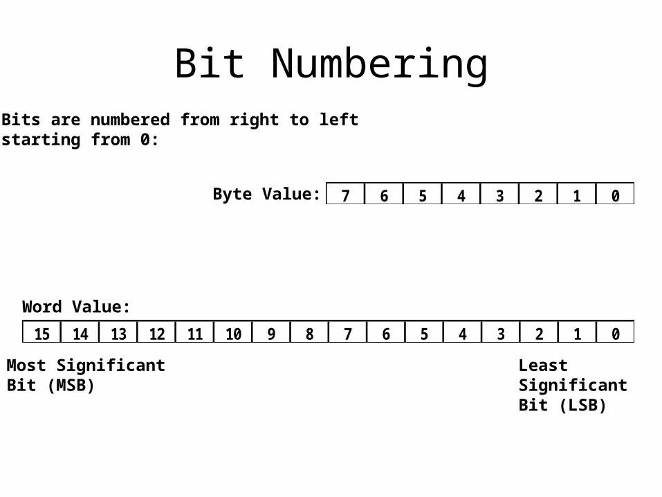
Bit Numbering
7 6 5 4 3 2 1 0
15 14 13 12 11 10 9 8 7 6 5 4 3 2 1 0
Bits are numbered from right to leftstarting from 0:
Byte Value:
Word Value:
Most Significant Bit (MSB)
Least Significant Bit (LSB)
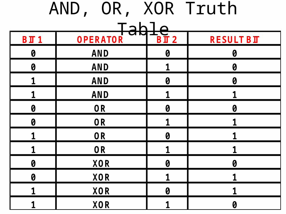
AND, OR, XOR Truth TableBIT 1 OPERATOR BIT 2 RESULT BIT
0 AND 0 0
0 AND 1 0
1 AND 0 0
1 AND 1 1
0 OR 0 0
0 OR 1 1
1 OR 0 1
1 OR 1 1
0 XOR 0 0
0 XOR 1 1
1 XOR 0 1
1 XOR 1 0
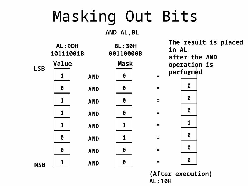
Masking Out Bits
1
0
1
1
1
0
0
1
0
0
0
0
1
1
0
0
AND
AND
AND
AND
AND
AND
AND
AND
0
0
0
0
1
0
0
0
=
=
=
=
=
=
=
=
AND AL,BL
BL:30H00110000B
Value Mask
AL:9DH10111001B
The result is placed in AL after the AND operation is performed
LSB
MSB
(After execution) AL:10H00010000B
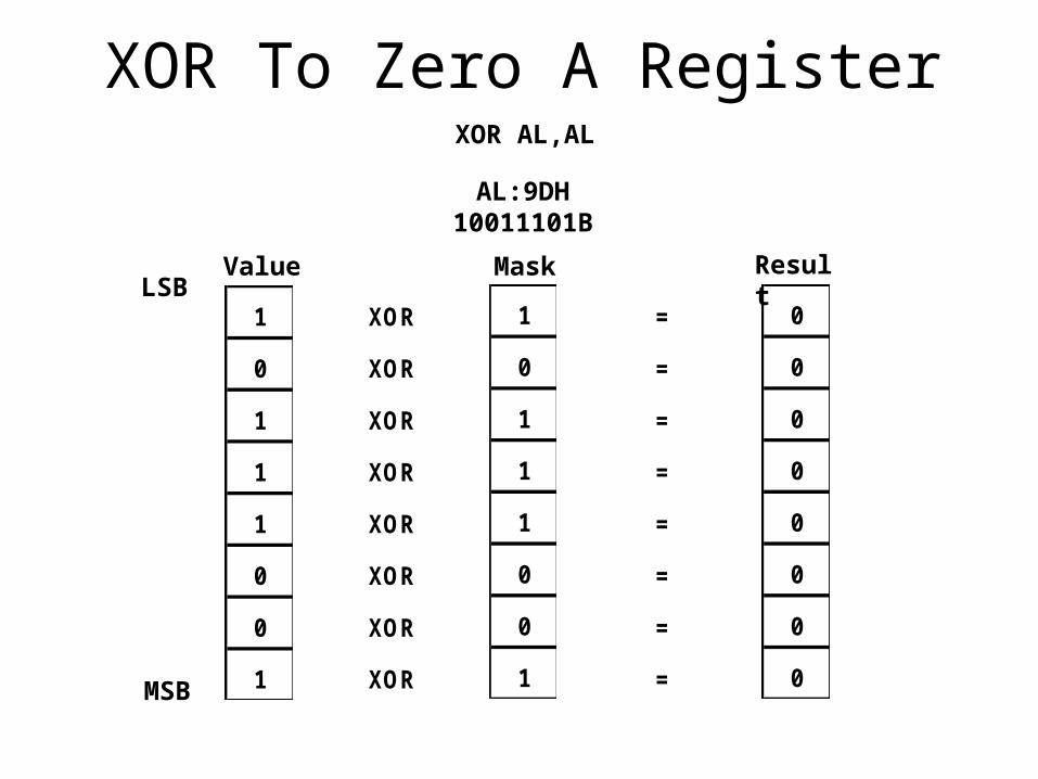
XOR To Zero A Register
1
0
1
1
1
0
0
1
XOR
XOR
XOR
XOR
XOR
XOR
XOR
XOR
0
0
0
0
0
0
0
0
=
=
=
=
=
=
=
=
Value MaskLSB
MSB
Result
1
0
1
1
1
0
0
1
XOR AL,AL
AL:9DH10011101B
Shifting Bits And Segment Register
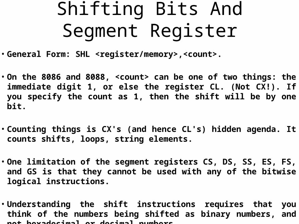
• General Form: SHL <register/memory>,<count>.
• On the 8086 and 8088, <count> can be one of two things: the immediate digit 1, or else the register CL. (Not CX!). If you specify the count as 1, then the shift will be by one bit.
• Counting things is CX's (and hence CL's) hidden agenda. It counts shifts, loops, string elements.
• One limitation of the segment registers CS, DS, SS, ES, FS, and GS is that they cannot be used with any of the bitwise logical instructions.
• Understanding the shift instructions requires that you think of the numbers being shifted as binary numbers, and not hexadecimal or decimal numbers.
Converting Numbers To Displayable Strings
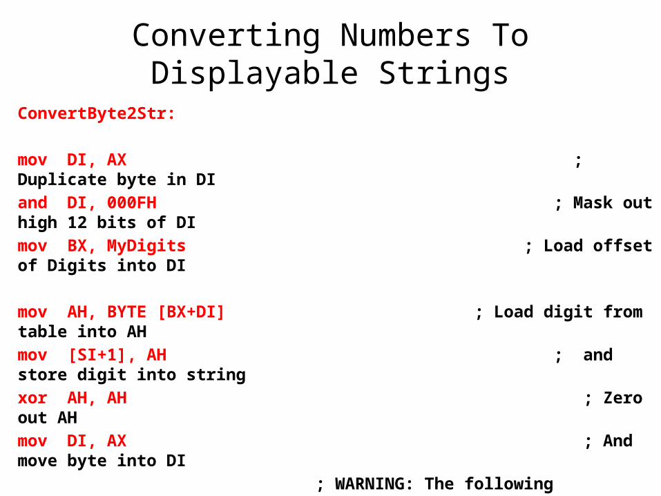
ConvertByte2Str:
mov DI, AX ; Duplicate byte in DI
and DI, 000FH ; Mask out high 12 bits of DI
mov BX, MyDigits ; Load offset of Digits into DI
mov AH, BYTE [BX+DI] ; Load digit from table into AH
mov [SI+1], AH ; and store digit into string
xor AH, AH ; Zero out AH
mov DI, AX ; And move byte into DI
; WARNING: The following instruction requires 286 or better!
shr DI, 4 ; Shift high nybble of byte to low
mov AH, BYTE [BX+DI] ; Load digit from table into AH
mov [SI], AH ; and store digit into string
ret ; We're done-go home!
MyDigits Lookup Table
0123456789ABCDEF
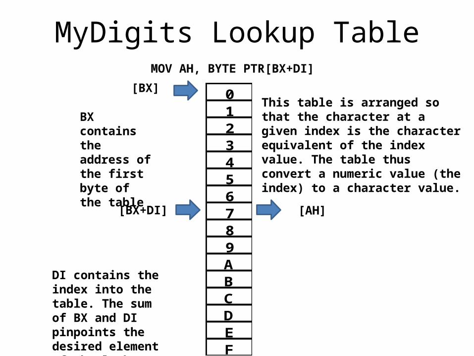
This table is arranged so that the character at a given index is the character equivalent of the index value. The table thus convert a numeric value (the index) to a character value.
MOV AH, BYTE PTR[BX+DI]
BX contains the address of the first byte of the table
DI contains the index into the table. The sum of BX and DI pinpoints the desired element of the lookup table
[BX]
[BX+DI] [AH]
Base Indexed And Indirect Displacement Addressing
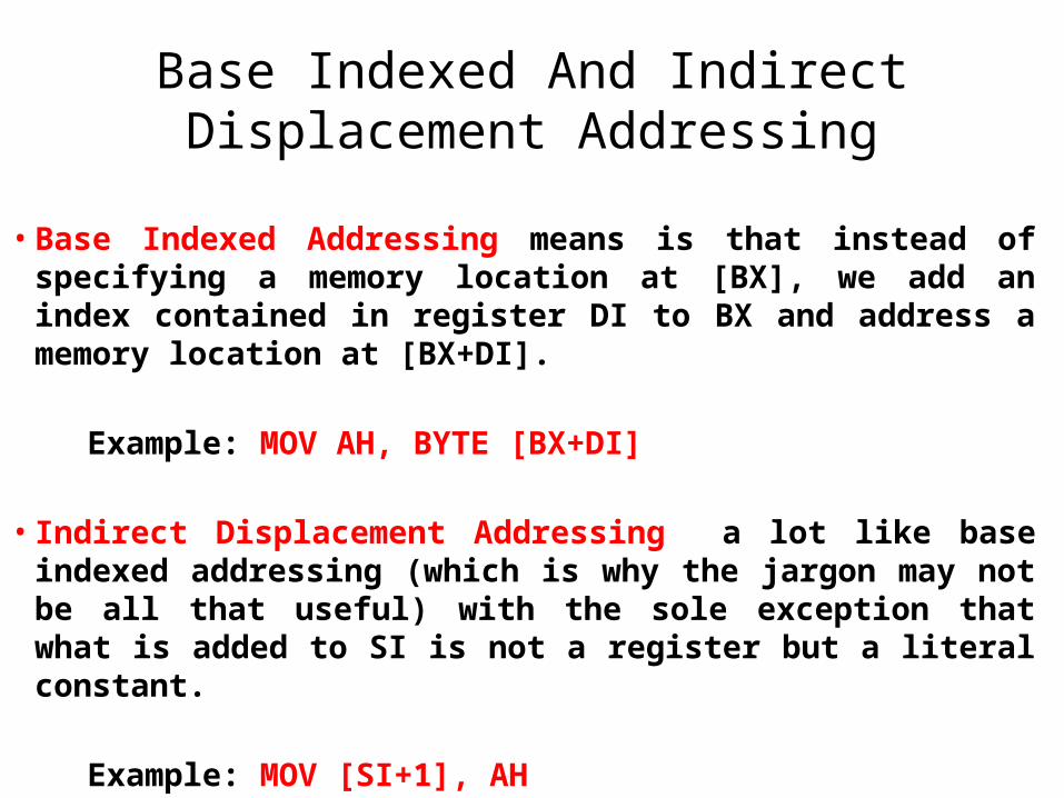
• Base Indexed Addressing means is that instead of specifying a memory location at [BX], we add an index contained in register DI to BX and address a memory location at [BX+DI].
Example: MOV AH, BYTE [BX+DI]
• Indirect Displacement Addressing a lot like base indexed addressing (which is why the jargon may not be all that useful) with the sole exception that what is added to SI is not a register but a literal constant.
Example: MOV [SI+1], AH
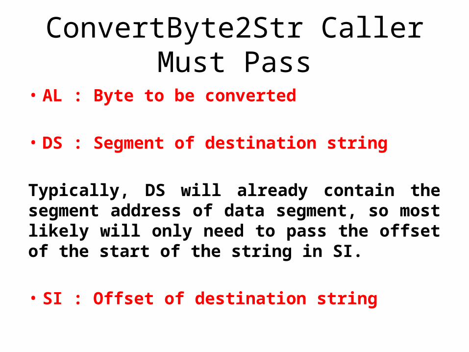
ConvertByte2Str Caller Must Pass
• AL : Byte to be converted
• DS : Segment of destination string
Typically, DS will already contain the segment address of data segment, so most likely will only need to pass the offset of the start of the string in SI.
• SI : Offset of destination string
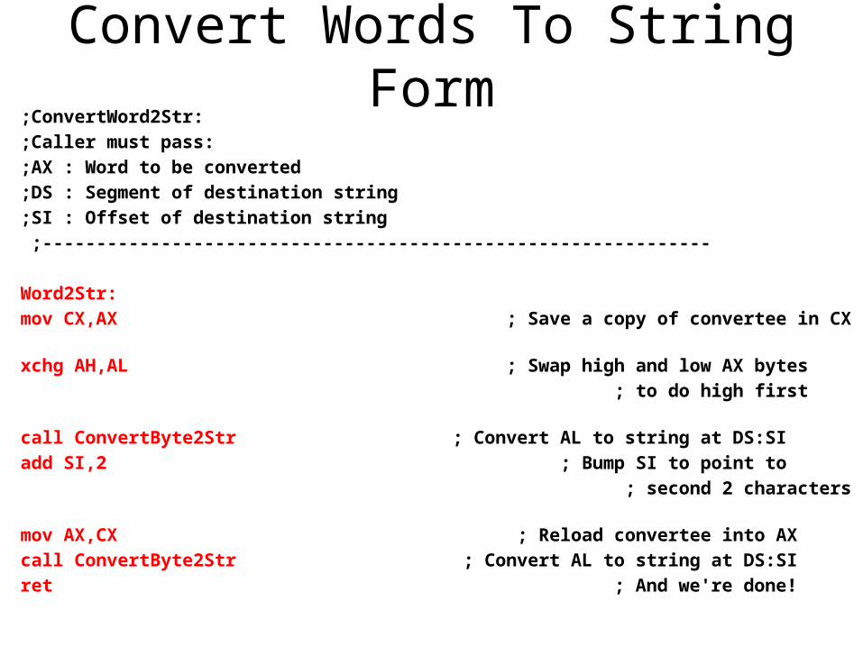
Convert Words To String Form;ConvertWord2Str:
;Caller must pass:
;AX : Word to be converted
;DS : Segment of destination string
;SI : Offset of destination string
;--------------------------------------------------------------
Word2Str:
mov CX,AX ; Save a copy of convertee in CX
xchg AH,AL ; Swap high and low AX bytes
; to do high first
call ConvertByte2Str ; Convert AL to string at DS:SI
add SI,2 ; Bump SI to point to
; second 2 characters
mov AX,CX ; Reload convertee into AX
call ConvertByte2Str ; Convert AL to string at DS:SI
ret ; And we're done!
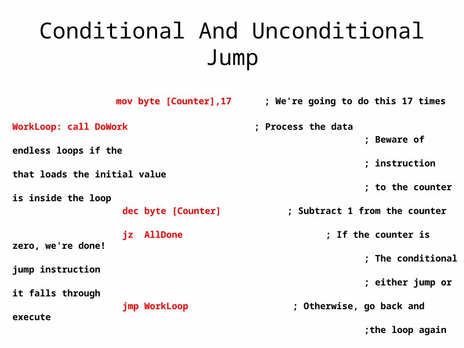
Conditional And Unconditional Jump
mov byte [Counter],17 ; We're going to do this 17 times
WorkLoop: call DoWork ; Process the data
; Beware of endless loops if the
; instruction that loads the initial value
; to the counter is inside the loop
dec byte [Counter] ; Subtract 1 from the counter
jz AllDone ; If the counter is zero, we're done!
; The conditional jump instruction
; either jump or it falls through
jmp WorkLoop ; Otherwise, go back and execute
;the loop again
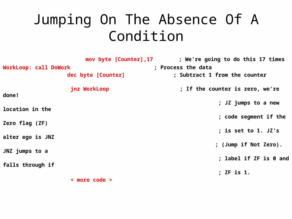
Jumping On The Absence Of A Condition
mov byte [Counter],17 ; We're going to do this 17 times
WorkLoop: call DoWork ; Process the data
dec byte [Counter] ; Subtract 1 from the counter
jnz WorkLoop ; If the counter is zero, we're done!
; JZ jumps to a new location in the
; code segment if the Zero flag (ZF)
; is set to 1. JZ's alter ego is JNZ
; (Jump if Not Zero). JNZ jumps to a
; label if ZF is 0 and falls through if
; ZF is 1.
< more code >
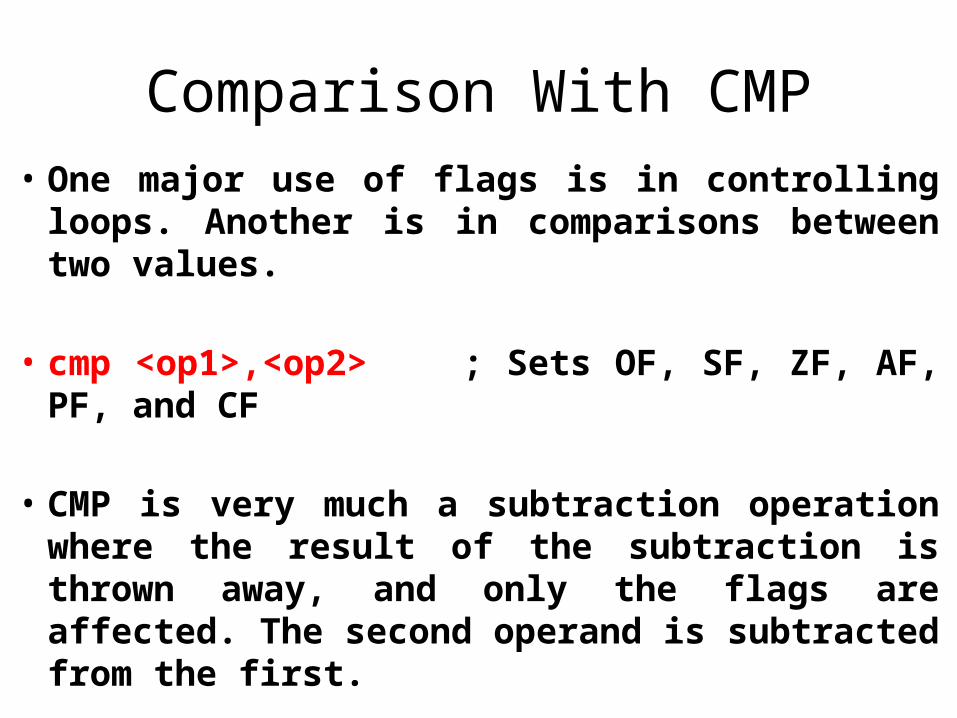
Comparison With CMP• One major use of flags is in controlling loops.
Another is in comparisons between two values.
• cmp <op1>,<op2> ; Sets OF, SF, ZF, AF, PF, and CF
• CMP is very much a subtraction operation where the result of the subtraction is thrown away, and only the flags are affected. The second operand is subtracted from the first.
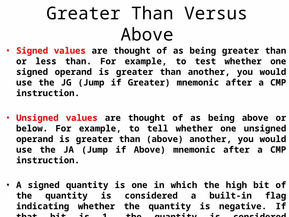
Greater Than Versus Above• Signed values are thought of as being greater than or less than.
For example, to test whether one signed operand is greater than another, you would use the JG (Jump if Greater) mnemonic after a CMP instruction.
• Unsigned values are thought of as being above or below. For example, to tell whether one unsigned operand is greater than (above) another, you would use the JA (Jump if Above) mnemonic after a CMP instruction.
• A signed quantity is one in which the high bit of the quantity is considered a built-in flag indicating whether the quantity is negative. If that bit is 1, the quantity is considered negative. If that bit is 0, the quantity is considered positive.
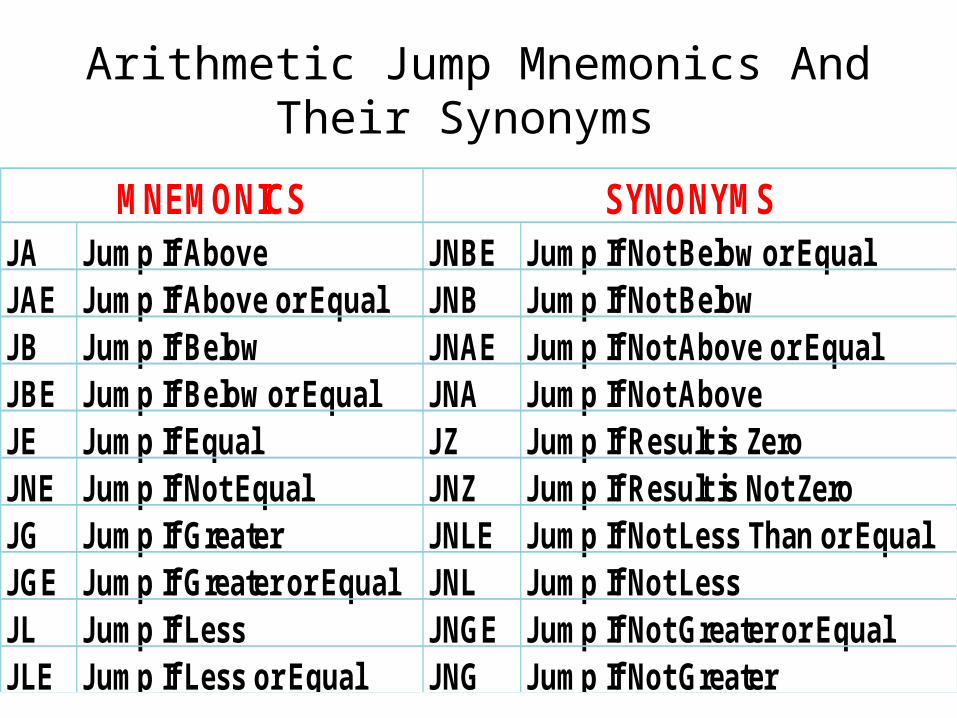
Arithmetic Jump Mnemonics And Their Synonyms
JA Jump If Above JNBE Jump If Not Below or EqualJAE Jump If Above or Equal JNB Jump If Not BelowJB Jump If Below JNAE Jump If Not Above or EqualJBE Jump If Below or Equal JNA Jump If Not AboveJE Jump If Equal JZ Jump If Result is ZeroJNE Jump If Not Equal JNZ Jump If Result is Not ZeroJG Jump If Greater JNLE Jump If Not Less Than or EqualJGE Jump If Greater or Equal JNL Jump If Not LessJL Jump If Less JNGE Jump If Not Greater or EqualJLE Jump If Less or Equal JNG Jump If Not Greater
MNEMONICS SYNONYMS
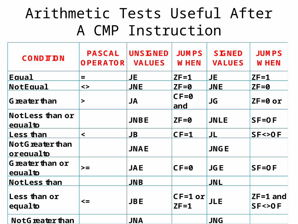
Arithmetic Tests Useful After A CMP Instruction
CONDITIONPASCAL
OPERATORUNSIGNED
VALUESJUMPS WHEN
SIGNED VALUES
JUMPS WHEN
Equal = JE ZF=1 JE ZF=1Not Equal <> JNE ZF=0 JNE ZF=0
Greater than > JA CF=0 and
JG ZF=0 or
Not Less than or equal to
JNBE ZF=0 JNLE SF=OF
Less than < JB CF=1 JL SF<>OFNot Greater than or equal to
JNAE JNGE
Greater than or equal to
>= JAE CF=0 JGE SF=OF
Not Less than JNB JNL
Less than or equal to
<= JBECF=1 or ZF=1
JLE ZF=1 and SF<>OF
Not Greater than JNA JNG
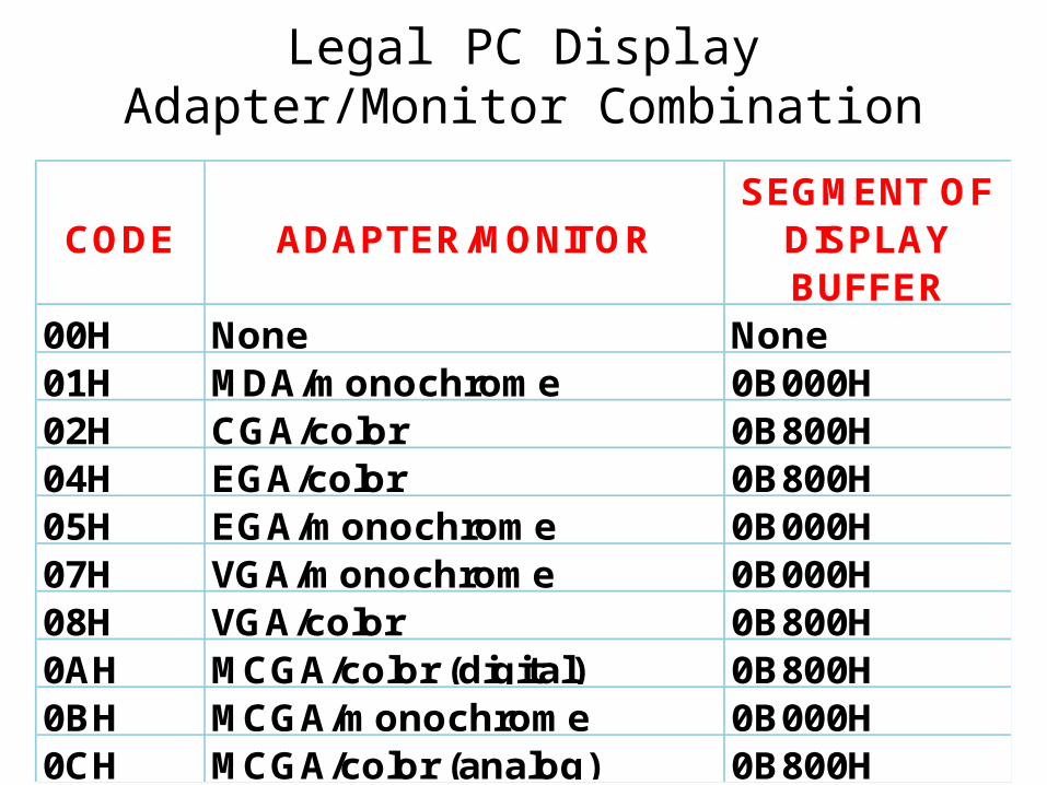
Legal PC Display Adapter/Monitor Combination
CODE ADAPTER/MONITORSEGMENT OF
DISPLAY BUFFER
00H None None01H MDA/monochrome 0B000H02H CGA/color 0B800H04H EGA/color 0B800H05H EGA/monochrome 0B000H07H VGA/monochrome 0B000H08H VGA/color 0B800H0AH MCGA/color (digital) 0B800H0BH MCGA/monochrome 0B000H0CH MCGA/color (analog) 0B800H
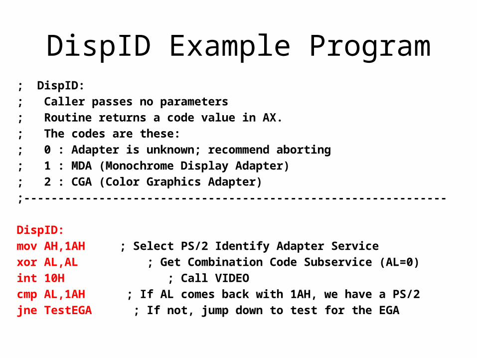
DispID Example Program; DispID:
; Caller passes no parameters
; Routine returns a code value in AX.
; The codes are these:
; 0 : Adapter is unknown; recommend aborting
; 1 : MDA (Monochrome Display Adapter)
; 2 : CGA (Color Graphics Adapter)
;--------------------------------------------------------------
DispID:
mov AH,1AH ; Select PS/2 Identify Adapter Service
xor AL,AL ; Get Combination Code Subservice (AL=0)
int 10H ; Call VIDEO
cmp AL,1AH ; If AL comes back with 1AH, we have a PS/2
jne TestEGA ; If not, jump down to test for the EGA
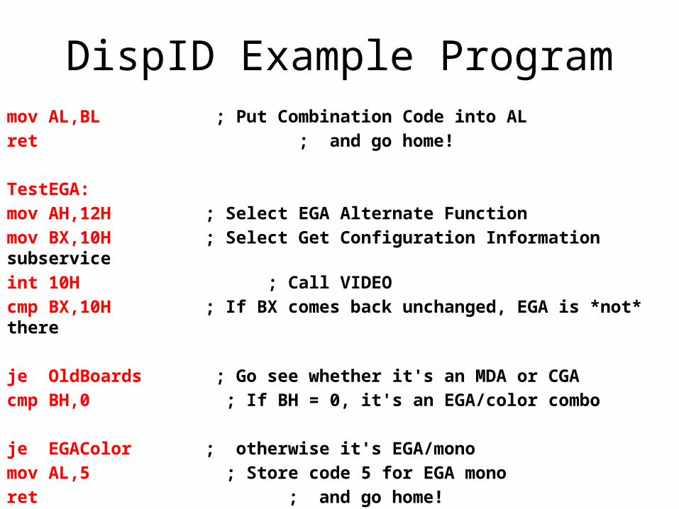
DispID Example Programmov AL,BL ; Put Combination Code into AL
ret ; and go home!
TestEGA:
mov AH,12H ; Select EGA Alternate Function
mov BX,10H ; Select Get Configuration Information subservice
int 10H ; Call VIDEO
cmp BX,10H ; If BX comes back unchanged, EGA is *not* there
je OldBoards ; Go see whether it's an MDA or CGA
cmp BH,0 ; If BH = 0, it's an EGA/color combo
je EGAColor ; otherwise it's EGA/mono
mov AL,5 ; Store code 5 for EGA mono
ret ; and go home!
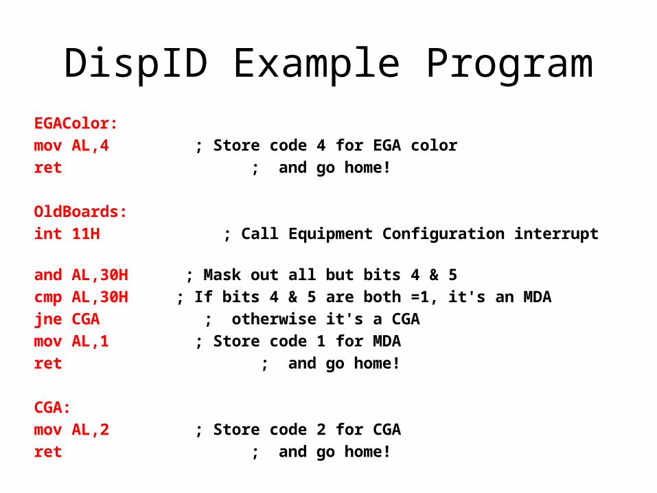
DispID Example ProgramEGAColor:
mov AL,4 ; Store code 4 for EGA color
ret ; and go home!
OldBoards:
int 11H ; Call Equipment Configuration interrupt
and AL,30H ; Mask out all but bits 4 & 5
cmp AL,30H ; If bits 4 & 5 are both =1, it's an MDA
jne CGA ; otherwise it's a CGA
mov AL,1 ; Store code 1 for MDA
ret ; and go home!
CGA:
mov AL,2 ; Store code 2 for CGA
ret ; and go home!
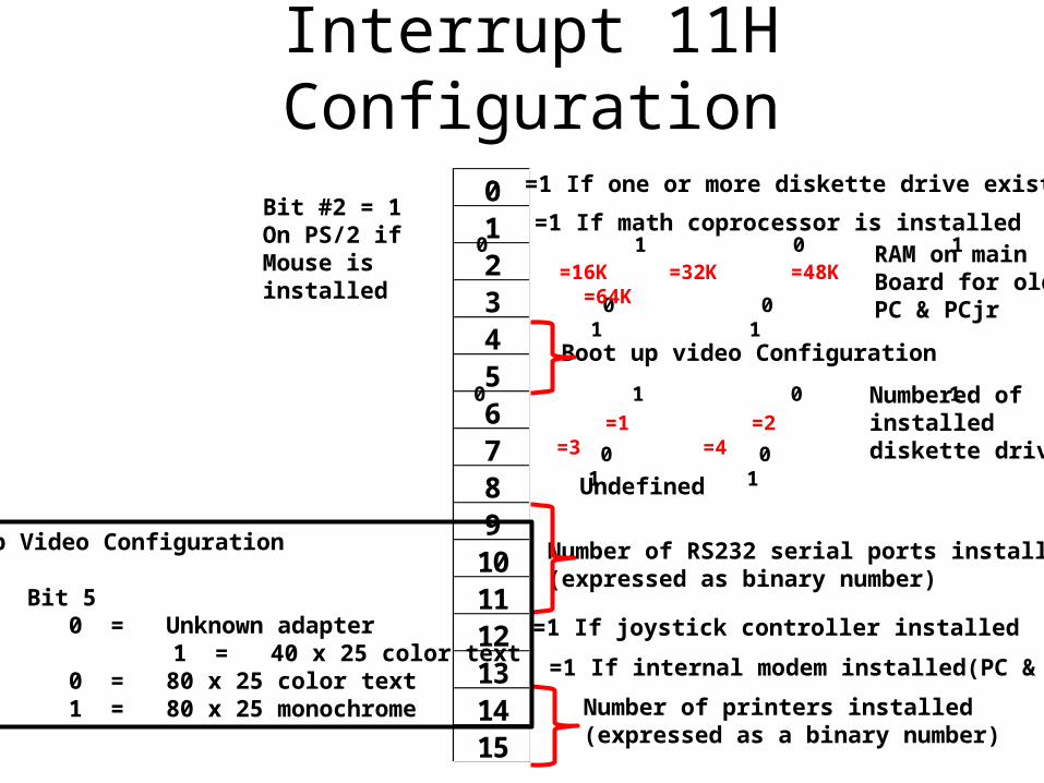
Interrupt 11H Configuration
0123456789101112131415
=1 If one or more diskette drive exist
=1 If math coprocessor is installed0 1 0 1
0 0 1 1
RAM on mainBoard for oldPC & PCjr
=16K =32K =48K =64K
Boot up video Configuration
0 1 0 1
0 0 1 1
=1 =2 =3 =4Numbered of installed diskette drive
Undefined
Number of RS232 serial ports installed(expressed as binary number)
=1 If joystick controller installed
=1 If internal modem installed(PC & XT)
Number of printers installed(expressed as a binary number)
Bit #2 = 1On PS/2 if Mouse isinstalled
Bootup Video Configuration
Bit 4 Bit 5 0 0 = Unknown adapter 0 1 = 40 x 25 color text 1 0 = 80 x 25 color text 1 1 = 80 x 25 monochrome
The Phantom Of The Opcodes
• TEST performs an AND logical operation between two operands, and then sets the flags as AND would, without altering the destination operation, as AND would.
• Key to understanding TEST is thinking of TEST as a sort of Phantom of the Opcode, where the Opcode is AND. TEST pretends it is AND, but doesn't follow through with the results of the operation. It simply sets the flags as though an AND operation had occurred.
• CMP is another Phantom of the Opcode and bears the same relation to SUB as TEST bears to AND.
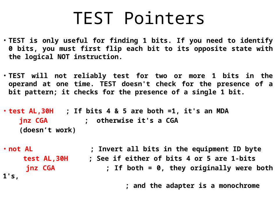
TEST Pointers• TEST is only useful for finding 1 bits. If you need to identify 0 bits,
you must first flip each bit to its opposite state with the logical NOT instruction.
• TEST will not reliably test for two or more 1 bits in the operand at one time. TEST doesn't check for the presence of a bit pattern; it checks for the presence of a single 1 bit.
• test AL,30H ; If bits 4 & 5 are both =1, it's an MDA
jnz CGA ; otherwise it's a CGA
(doesn’t work)
• not AL ; Invert all bits in the equipment ID byte
test AL,30H ; See if either of bits 4 or 5 are 1-bits
jnz CGA ; If both = 0, they originally were both 1's,
; and the adapter is a monochrome
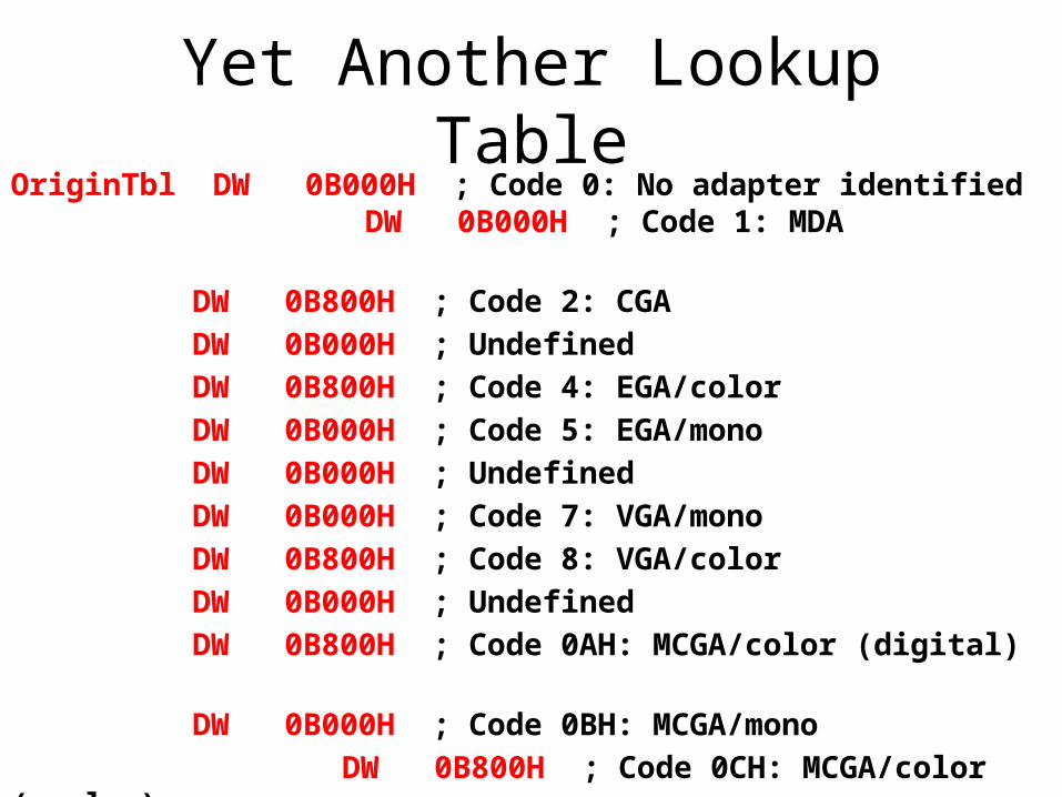
Yet Another Lookup TableOriginTbl DW 0B000H ; Code 0: No adapter identified DW 0B000H ; Code 1: MDA
DW 0B800H ; Code 2: CGA
DW 0B000H ; Undefined
DW 0B800H ; Code 4: EGA/color
DW 0B000H ; Code 5: EGA/mono
DW 0B000H ; Undefined
DW 0B000H ; Code 7: VGA/mono
DW 0B800H ; Code 8: VGA/color
DW 0B000H ; Undefined
DW 0B800H ; Code 0AH: MCGA/color (digital)
DW 0B000H ; Code 0BH: MCGA/mono
DW 0B800H ; Code 0CH: MCGA/color (analog)
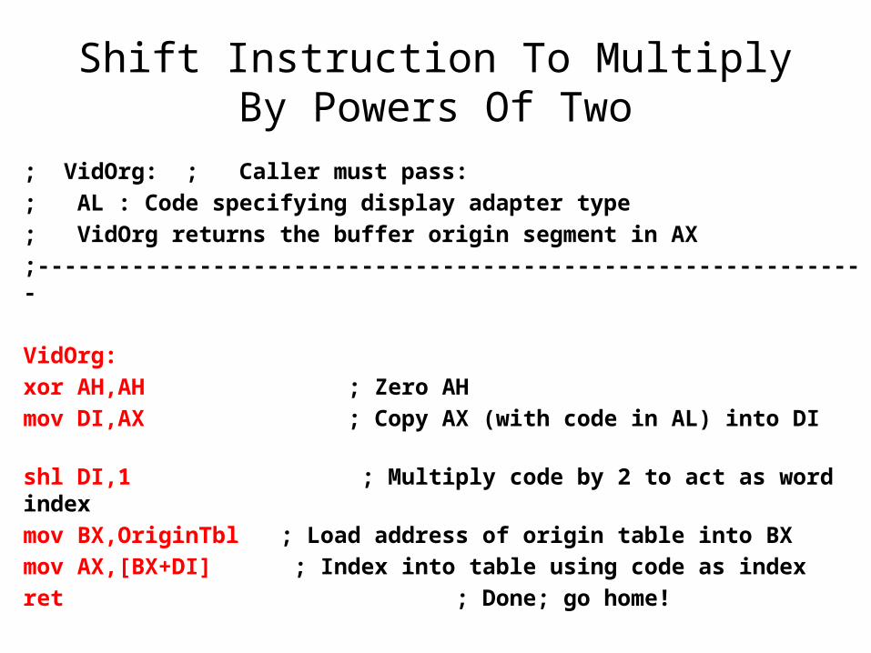
Shift Instruction To Multiply By Powers Of Two
; VidOrg: ; Caller must pass:
; AL : Code specifying display adapter type
; VidOrg returns the buffer origin segment in AX
;--------------------------------------------------------------
VidOrg:
xor AH,AH ; Zero AH
mov DI,AX ; Copy AX (with code in AL) into DI
shl DI,1 ; Multiply code by 2 to act as word index
mov BX,OriginTbl ; Load address of origin table into BX
mov AX,[BX+DI] ; Index into table using code as index
ret ; Done; go home!
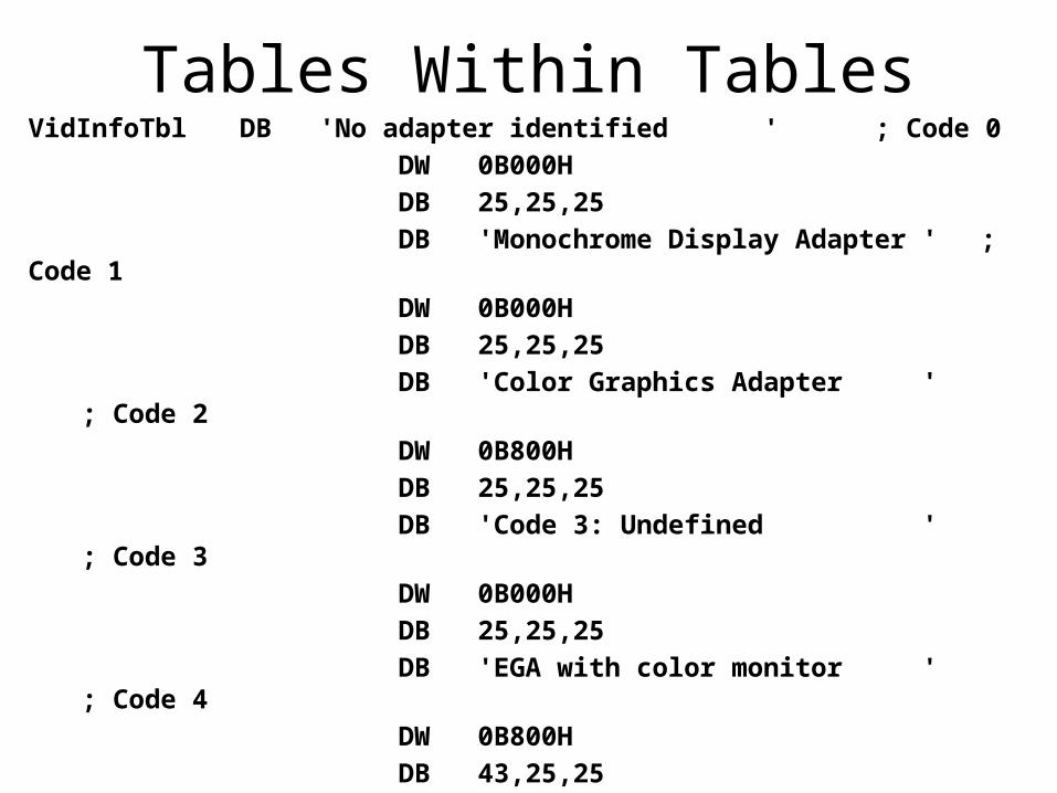
Tables Within TablesVidInfoTbl DB 'No adapter identified ' ; Code 0
DW 0B000H
DB 25,25,25
DB 'Monochrome Display Adapter ' ; Code 1
DW 0B000H
DB 25,25,25
DB 'Color Graphics Adapter ' ; Code 2
DW 0B800H
DB 25,25,25
DB 'Code 3: Undefined ' ; Code 3
DW 0B000H
DB 25,25,25
DB 'EGA with color monitor ' ; Code 4
DW 0B800H
DB 43,25,25
DB 'EGA with mono monitor ' ; Code 5
DW 0B000H
DB 43,25,25
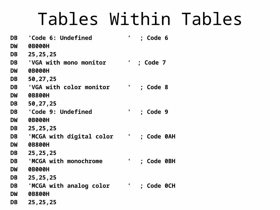
Tables Within TablesDB 'Code 6: Undefined ' ; Code 6
DW 0B000H
DB 25,25,25
DB 'VGA with mono monitor ‘ ; Code 7
DW 0B000H
DB 50,27,25
DB 'VGA with color monitor ' ; Code 8
DW 0B800H
DB 50,27,25
DB 'Code 9: Undefined ' ; Code 9
DW 0B000H
DB 25,25,25
DB 'MCGA with digital color ' ; Code 0AH
DW 0B800H
DB 25,25,25
DB 'MCGA with monochrome ' ; Code 0BH
DW 0B000H
DB 25,25,25
DB 'MCGA with analog color ' ; Code 0CH
DW 0B800H
DB 25,25,25
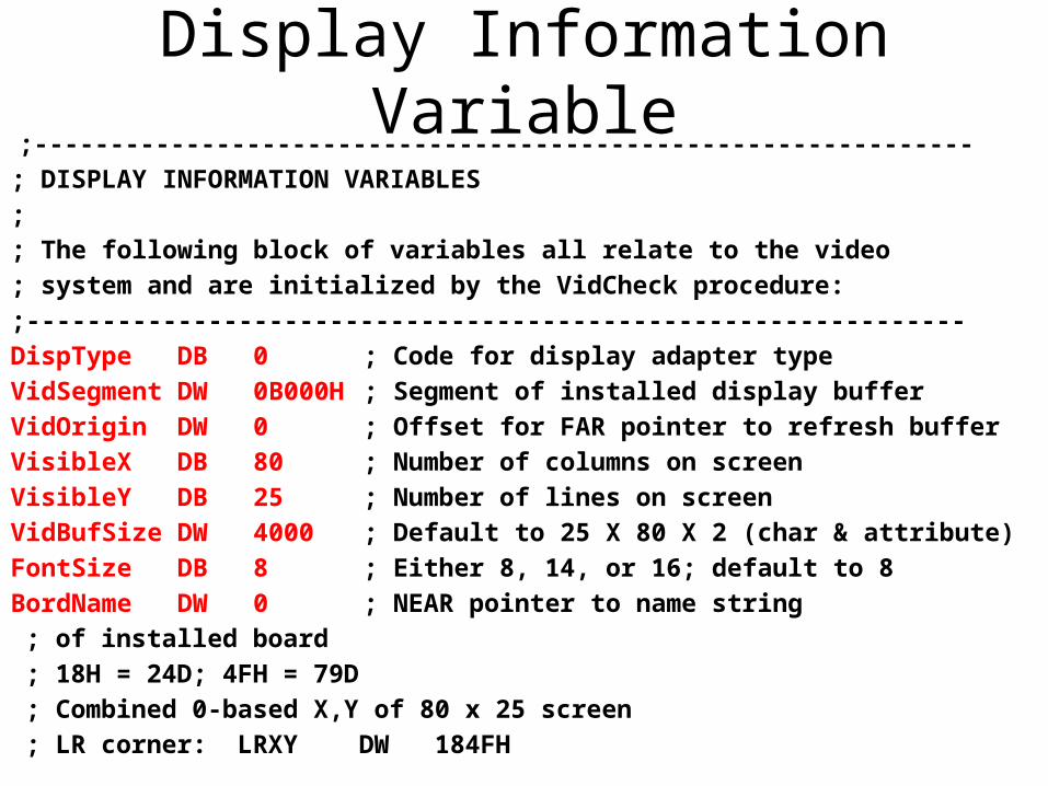
Display Information Variable ;--------------------------------------------------------------
; DISPLAY INFORMATION VARIABLES
;
; The following block of variables all relate to the video
; system and are initialized by the VidCheck procedure:
;--------------------------------------------------------------
DispType DB 0 ; Code for display adapter type
VidSegment DW 0B000H ; Segment of installed display buffer
VidOrigin DW 0 ; Offset for FAR pointer to refresh buffer
VisibleX DB 80 ; Number of columns on screen
VisibleY DB 25 ; Number of lines on screen
VidBufSize DW 4000 ; Default to 25 X 80 X 2 (char & attribute)
FontSize DB 8 ; Either 8, 14, or 16; default to 8
BordName DW 0 ; NEAR pointer to name string
; of installed board
; 18H = 24D; 4FH = 79D
; Combined 0-based X,Y of 80 x 25 screen
; LR corner: LRXY DW 184FH
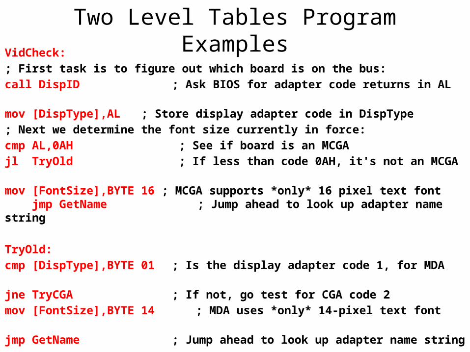
Two Level Tables Program ExamplesVidCheck:
; First task is to figure out which board is on the bus:
call DispID ; Ask BIOS for adapter code returns in AL
mov [DispType],AL ; Store display adapter code in DispType
; Next we determine the font size currently in force:
cmp AL,0AH ; See if board is an MCGA
jl TryOld ; If less than code 0AH, it's not an MCGA
mov [FontSize],BYTE 16 ; MCGA supports *only* 16 pixel text font jmp GetName ; Jump ahead to look up adapter name string
TryOld:
cmp [DispType],BYTE 01 ; Is the display adapter code 1, for MDA
jne TryCGA ; If not, go test for CGA code 2
mov [FontSize],BYTE 14 ; MDA uses *only* 14-pixel text font
jmp GetName ; Jump ahead to look up adapter name string
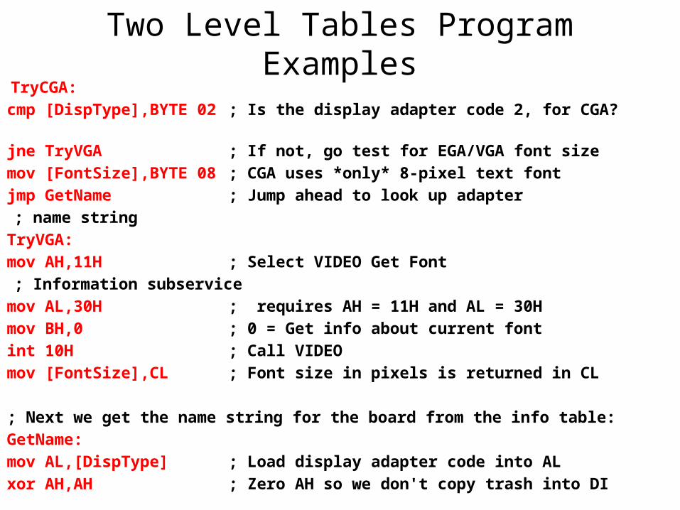
Two Level Tables Program Examples TryCGA:
cmp [DispType],BYTE 02 ; Is the display adapter code 2, for CGA?
jne TryVGA ; If not, go test for EGA/VGA font size
mov [FontSize],BYTE 08 ; CGA uses *only* 8-pixel text font
jmp GetName ; Jump ahead to look up adapter
; name string
TryVGA:
mov AH,11H ; Select VIDEO Get Font
; Information subservice
mov AL,30H ; requires AH = 11H and AL = 30H
mov BH,0 ; 0 = Get info about current font
int 10H ; Call VIDEO
mov [FontSize],CL ; Font size in pixels is returned in CL
; Next we get the name string for the board from the info table:
GetName:
mov AL,[DispType] ; Load display adapter code into AL
xor AH,AH ; Zero AH so we don't copy trash into DI
mov DI,AX ; Copy AX (with code in AL) into DI
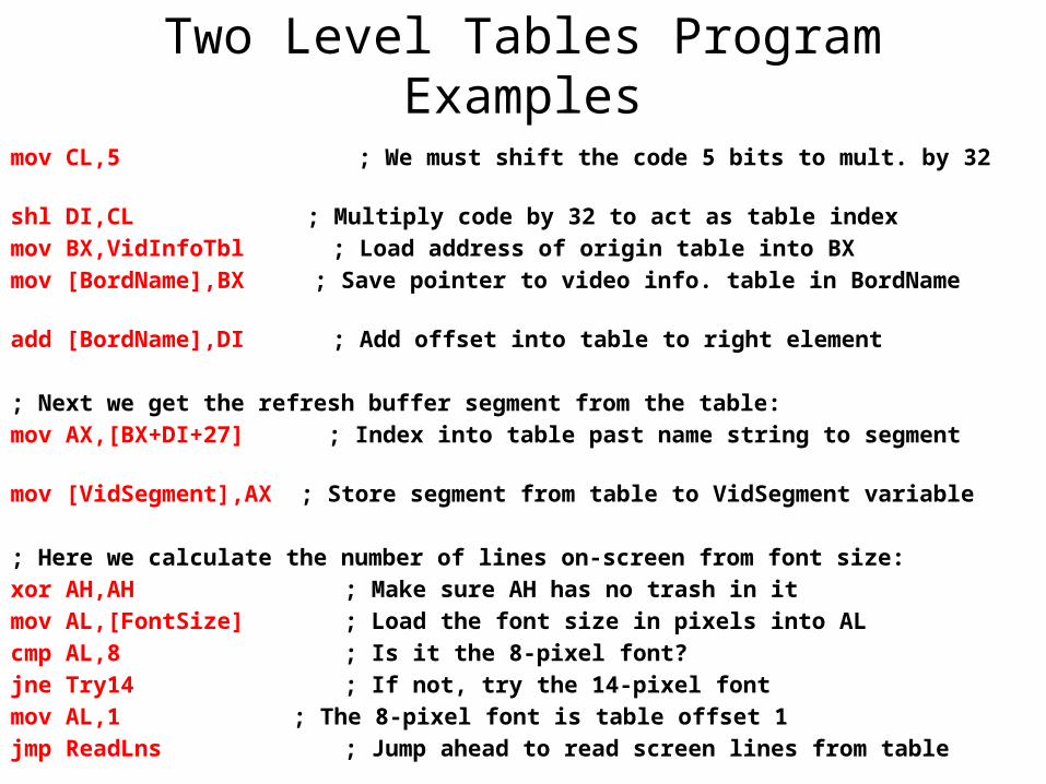
Two Level Tables Program Examplesmov CL,5 ; We must shift the code 5 bits to mult. by 32
shl DI,CL ; Multiply code by 32 to act as table index
mov BX,VidInfoTbl ; Load address of origin table into BX
mov [BordName],BX ; Save pointer to video info. table in BordName
add [BordName],DI ; Add offset into table to right element
; Next we get the refresh buffer segment from the table:
mov AX,[BX+DI+27] ; Index into table past name string to segment
mov [VidSegment],AX ; Store segment from table to VidSegment variable
; Here we calculate the number of lines on-screen from font size:
xor AH,AH ; Make sure AH has no trash in it
mov AL,[FontSize] ; Load the font size in pixels into AL
cmp AL,8 ; Is it the 8-pixel font?
jne Try14 ; If not, try the 14-pixel font
mov AL,1 ; The 8-pixel font is table offset 1
jmp ReadLns ; Jump ahead to read screen lines from table
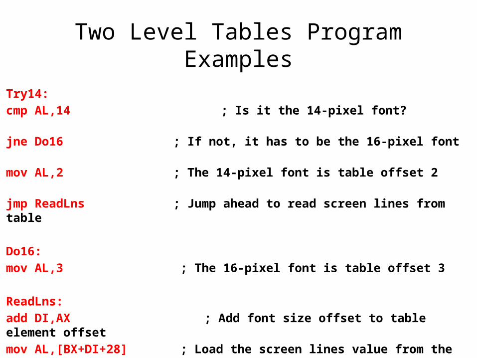
Two Level Tables Program Examples
Try14:
cmp AL,14 ; Is it the 14-pixel font?
jne Do16 ; If not, it has to be the 16-pixel font
mov AL,2 ; The 14-pixel font is table offset 2
jmp ReadLns ; Jump ahead to read screen lines from table
Do16:
mov AL,3 ; The 16-pixel font is table offset 3
ReadLns:
add DI,AX ; Add font size offset to table element offset
mov AL,[BX+DI+28] ; Load the screen lines value from the table
mov [VisibleY],AL ; and store it in the VisibleY variable
mov AH,[VisibleX] ; Load the screen columns value to AH
xchg AH,AL ; Exchange AH & AL for 0-basing
Two Level Tables Program Examples
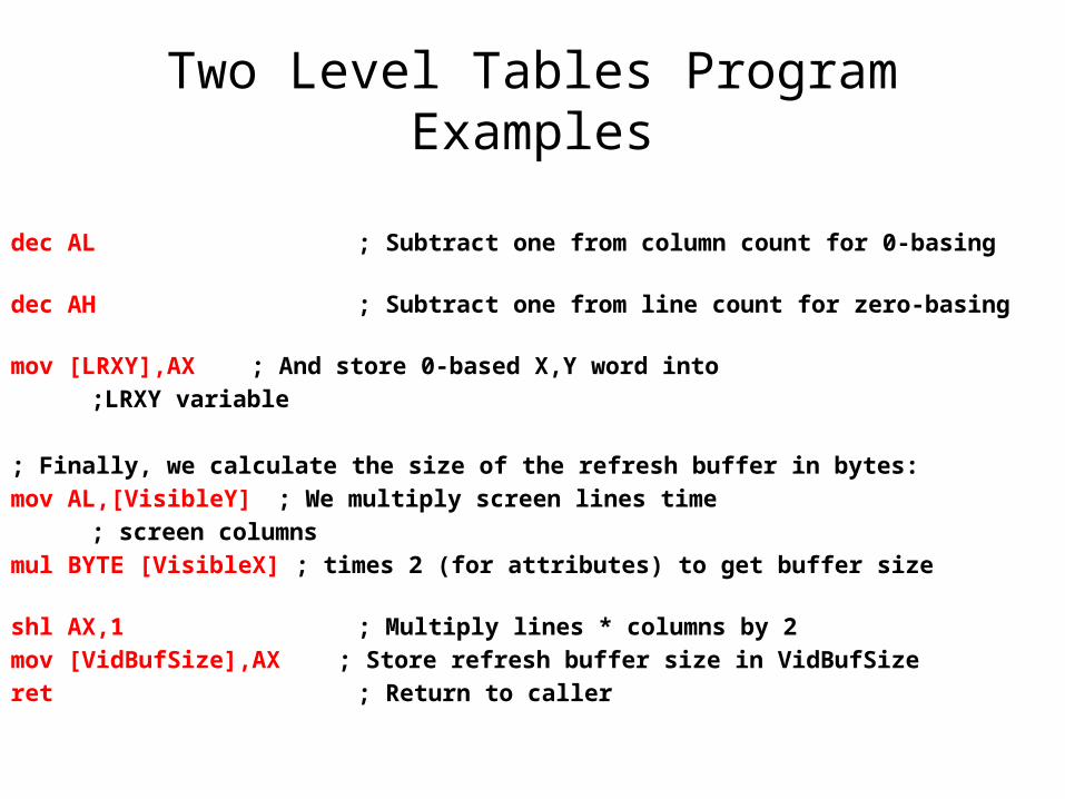
dec AL ; Subtract one from column count for 0-basing
dec AH ; Subtract one from line count for zero-basing
mov [LRXY],AX ; And store 0-based X,Y word into
;LRXY variable
; Finally, we calculate the size of the refresh buffer in bytes:
mov AL,[VisibleY] ; We multiply screen lines time
; screen columns
mul BYTE [VisibleX] ; times 2 (for attributes) to get buffer size
shl AX,1 ; Multiply lines * columns by 2
mov [VidBufSize],AX ; Store refresh buffer size in VidBufSize
ret ; Return to caller
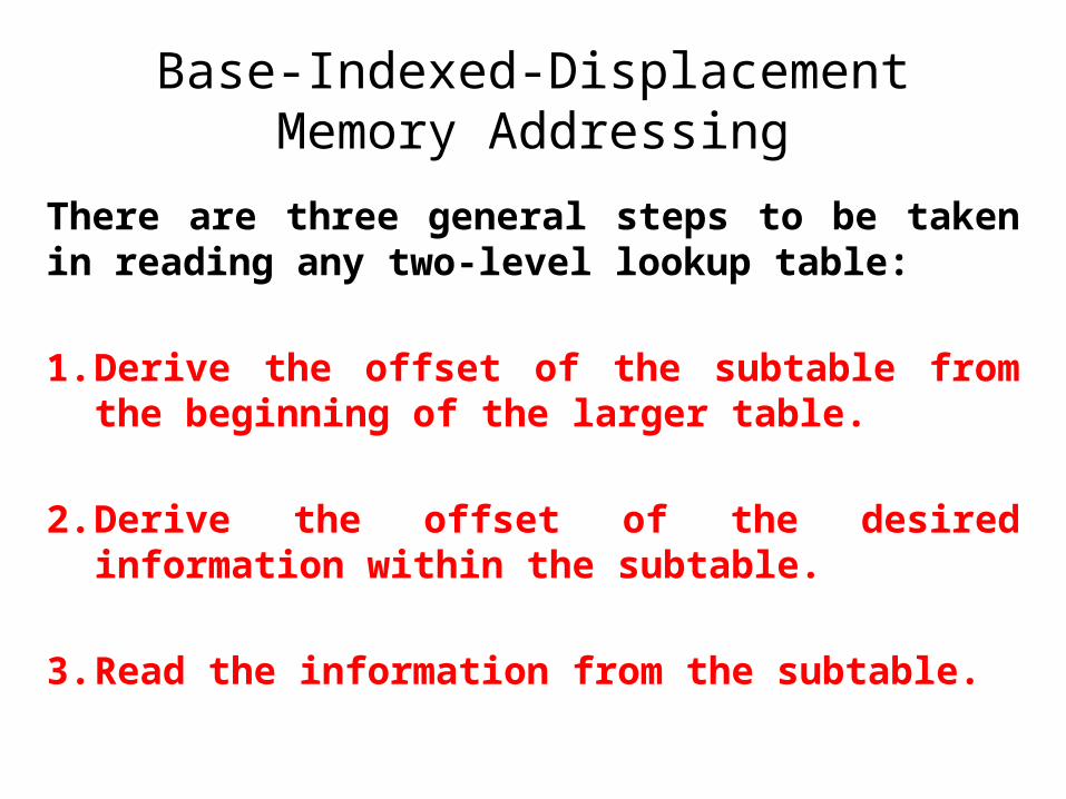
Base-Indexed-Displacement Memory Addressing
There are three general steps to be taken in reading any two-level lookup table:
1. Derive the offset of the subtable from the beginning of the larger table.
2. Derive the offset of the desired information within the subtable.
3. Read the information from the subtable.
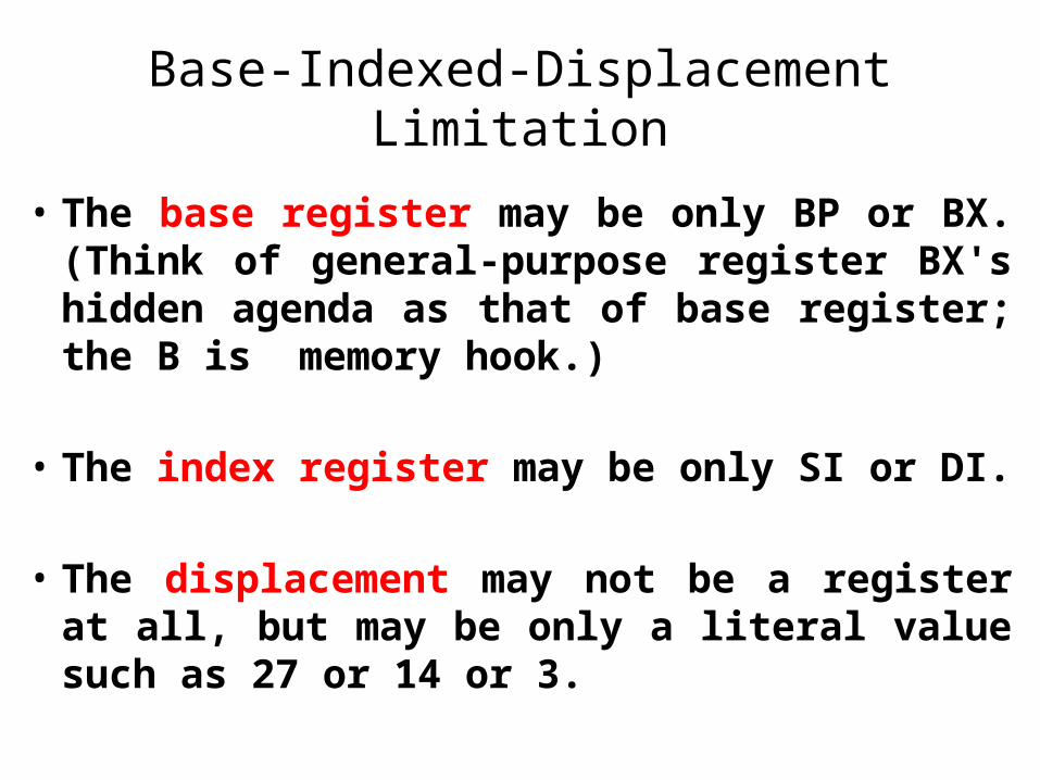
Base-Indexed-Displacement Limitation
• The base register may be only BP or BX. (Think of general-purpose register BX's hidden agenda as that of base register; the B is memory hook.)
• The index register may be only SI or DI.
• The displacement may not be a register at all, but may be only a literal value such as 27 or 14 or 3.
C Function That Has Buffer Overflow
• Gets()
• Scanf()
• Strcpy()
• Strcat()
The Heap And Stack• The heap is a dynamic storage location that does not have
sequential constraints or an organizational scheme. It is considered the larger pool of free storage for programs to use as needed. Once the dynamic memory space is no longer needed and the program has retrieved the needed data, the occupied space in the heap is freed up for future use.
• The stack refers to the smaller pool of free storage: memory allocated to a program for short-term processing. This is the main action area, where program variables are temporarily stored, added, and removed as needed to perform a specific function. Another name for this kind of access is last-in, first-out (LIFO). The last item to be stacked is the first item to be removed.
Smashing The Stack
• “Smashing” the stack refers to the use of buffer overflow to compromise the stack integrity and gain program-level access for running malicious code.
• Smashing the stack modifies normal stack operation by submitting excess data to the stack, surpassing its normal bounds (if left unchecked).
• The excess data overwrites legitimate variables in the stack and resets the saved Extended Instruction Pointer (EIP) value to point to the injected malicious code.
Buffer Overflow Effect
• The OS terminates the offending program due to the program operating outside its allotted memory space.
• The address of the hacker’s malicious code, which now resides in the overflowed stack, winds up in the EIP, causing that code to execute.
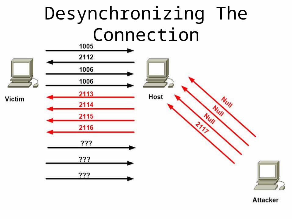
Desynchronizing The Connection
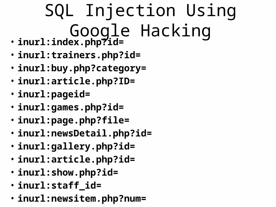
SQL Injection Using Google Hacking• inurl:index.php?id= • inurl:trainers.php?id= • inurl:buy.php?category= • inurl:article.php?ID= • inurl:pageid= • inurl:games.php?id= • inurl:page.php?file= • inurl:newsDetail.php?id= • inurl:gallery.php?id= • inurl:article.php?id= • inurl:show.php?id= • inurl:staff_id= • inurl:newsitem.php?num=
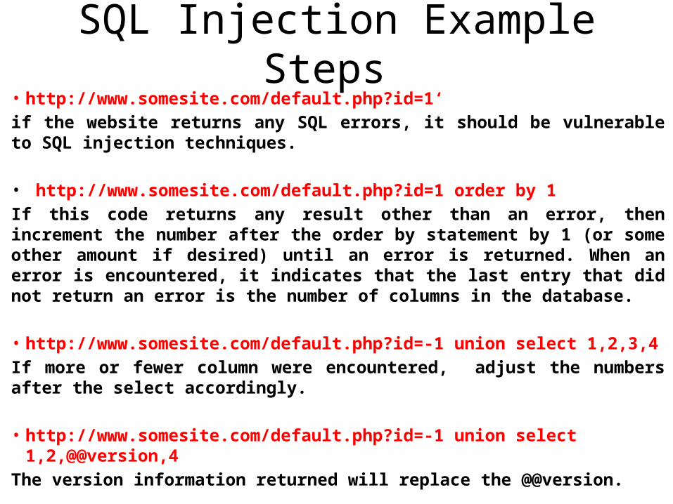
SQL Injection Example Steps • http://www.somesite.com/default.php?id=1‘
if the website returns any SQL errors, it should be vulnerable to SQL injection techniques.
• http://www.somesite.com/default.php?id=1 order by 1
If this code returns any result other than an error, then increment the number after the order by statement by 1 (or some other amount if desired) until an error is returned. When an error is encountered, it indicates that the last entry that did not return an error is the number of columns in the database.
• http://www.somesite.com/default.php?id=-1 union select 1,2,3,4
If more or fewer column were encountered, adjust the numbers after the select accordingly.
• http://www.somesite.com/default.php?id=-1 union select 1,2,@@version,4
The version information returned will replace the @@version.
Metasploit Filesystem
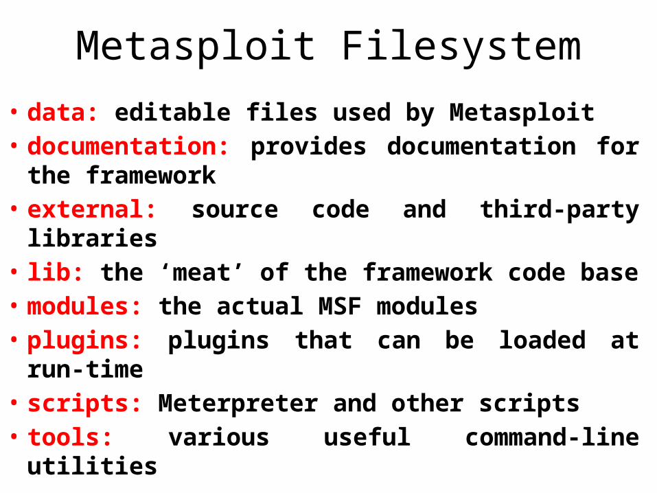
• data: editable files used by Metasploit• documentation: provides documentation for
the framework• external: source code and third-party libraries• lib: the ‘meat’ of the framework code base• modules: the actual MSF modules• plugins: plugins that can be loaded at run-
time• scripts: Meterpreter and other scripts• tools: various useful command-line utilities
Metasploit Libraries
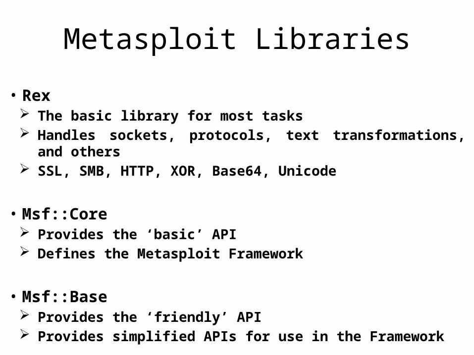
• Rex The basic library for most tasks Handles sockets, protocols, text transformations, and others SSL, SMB, HTTP, XOR, Base64, Unicode
• Msf::Core Provides the ‘basic’ API Defines the Metasploit Framework
• Msf::Base Provides the ‘friendly’ API Provides simplified APIs for use in the Framework
Metasploit Active And Passive Exploit
• Active exploits will exploit a specific host, run until completion, and then exit. Brute-force modules will exit when a shell opens from the victim. Module execution stops if an error is encountered. You can force an active module to the background by passing ‘-j’
to the exploit command
• Passive exploits wait for incoming hosts and exploit them as they connect. Passive exploits almost always focus on clients such as web
browsers, FTP clients, etc. They can also be used in conjunction with email exploits, waiting
for connections. Passive exploits report shells as they happen can be enumerated
by passing ‘-l’ to the sessions command. Passing ‘-i’ will interact with a shell.
Three Different Payload Modules• Singles
payloads that are self-contained and completely standalone. A Single payload can be something as simple as adding a user to the target system or running calc.exe.
• Stagers Stagers setup a network connection between the attacker and
victim and are designed to be small and reliable. It is difficult to always do both of these well so the result is multiple similar stagers. Metasploit will use the best one when it can and fall back to a less-preferred one when necessary.
• Stages payload components that are downloaded by Stagers modules.
The various payload stages provide advanced features with no size limits such as Meterpreter, VNC Injection, and the iPhone ‘ipwn’ Shell.
Payload Types• Inline (Non Staged)
A single payload containing the exploit and full shell code for the selected task. Inline payloads are by design more stable than their counterparts because they contain everything all in one. However some exploits wont support the resulting size of these payloads.
• Staged Stager payloads work in conjunction with stage payloads in order
to perform a specific task. A stager establishes a communication channel between the attacker and the victim and reads in a stage payload to execute on the remote host.
• Meterpreter Meterpreter, the short form of Meta-Interpreter is an advanced,
multi-faceted payload that operates via dll injection. The Meterpreter resides completely in the memory of the remote host and leaves no traces on the hard drive, making it very difficult to detect with conventional forensic techniques. Scripts and plugins can be loaded and unloaded dynamically as required.
Payload Types• PassiveX
PassiveX is a payload that can help in circumventing restrictive outbound firewalls. It does this by using an ActiveX control to create a hidden instance of Internet Explorer. Using the new ActiveX control, it communicates with the attacker via HTTP requests and responses.
• NoNX The NX (No eXecute) bit is a feature built into some CPUs to prevent code from
executing in certain areas of memory. In Windows, NX is implemented as Data Execution Prevention (DEP). The Metasploit NoNX payloads are designed to circumvent DEP.
• Ord Ordinal payloads are Windows stager based payloads that have distinct advantages
and disadvantages. The advantages being it works on every flavor and language of Windows dating back to Windows 9x without the explicit definition of a return address. They are also extremely tiny. However two very specific disadvantages make them not the default choice. The first being that it relies on the fact that ws2_32.dll is loaded in the process being exploited before exploitation. The second being that it’s a bit less stable than the other stagers.
Payload Types• IPv6
The Metasploit IPv6 payloads, as the name indicates, are built to function over IPv6 networks.
• Reflective DLL injectionReflective DLL Injection is a technique whereby
a stage payload is injected into a compromised host process running in memory, never touching the host hard drive. The VNC and Meterpreter payloads both make use of reflective DLL injection.
How Meterpreter Works
• The target executes the initial stager. This is usually one of bind, reverse, findtag, passivex, etc.
• The stager loads the DLL prefixed with Reflective. The Reflective stub handles the loading/injection of the DLL.
• The Metepreter core initializes, establishes a TLS/1.0 link over the socket and sends a GET. Metasploit receives this GET and configures the client.
• Lastly, Meterpreter loads extensions. It will always load stdapi and will load priv if the module gives administrative rights. All of these extensions are loaded over TLS/1.0 using a TLV protocol.
Fuzzer
• Fuzzer is a tool used by security professionals to provide invalid and unexpected data to the inputs of a program.
• A typical Fuzzer tests an application for buffer overflow, invalid format strings, directory traversal attacks, command execution vulnerabilities, SQL Injection, XSS