Embed Size (px)
Citation preview
Rahim GoharMedical PhysicistDr Ziauddin Hospital
1
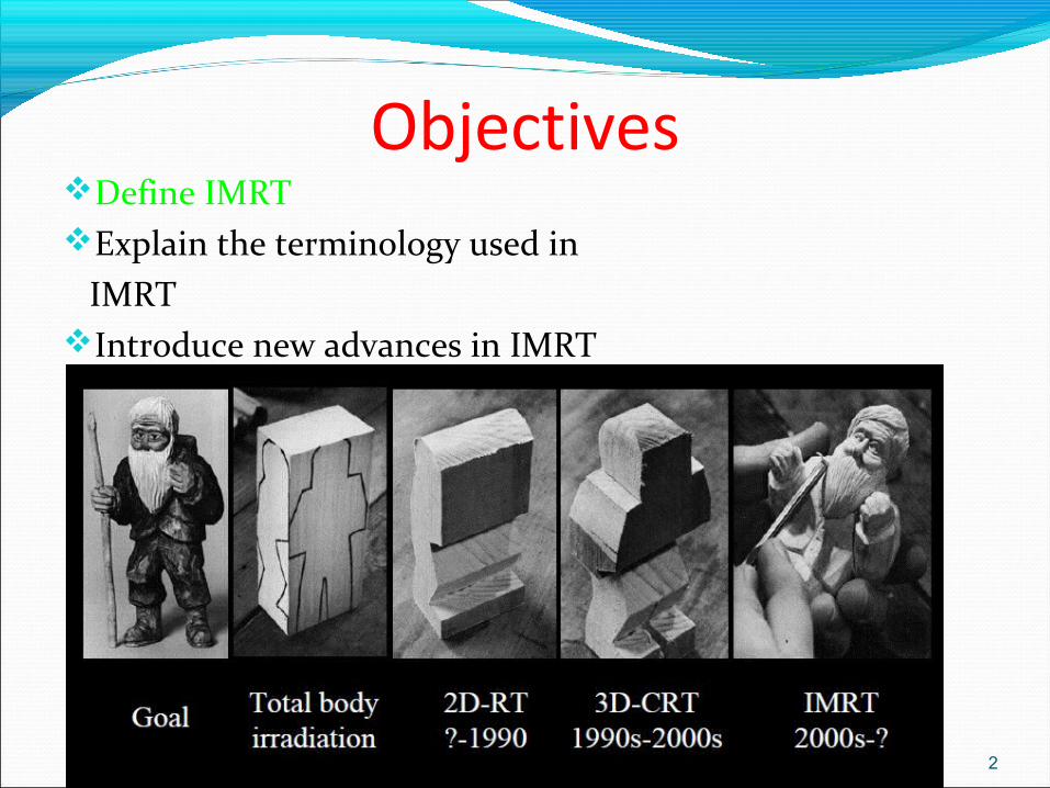
ObjectivesDefine IMRTExplain the terminology used in IMRTIntroduce new advances in IMRT
2
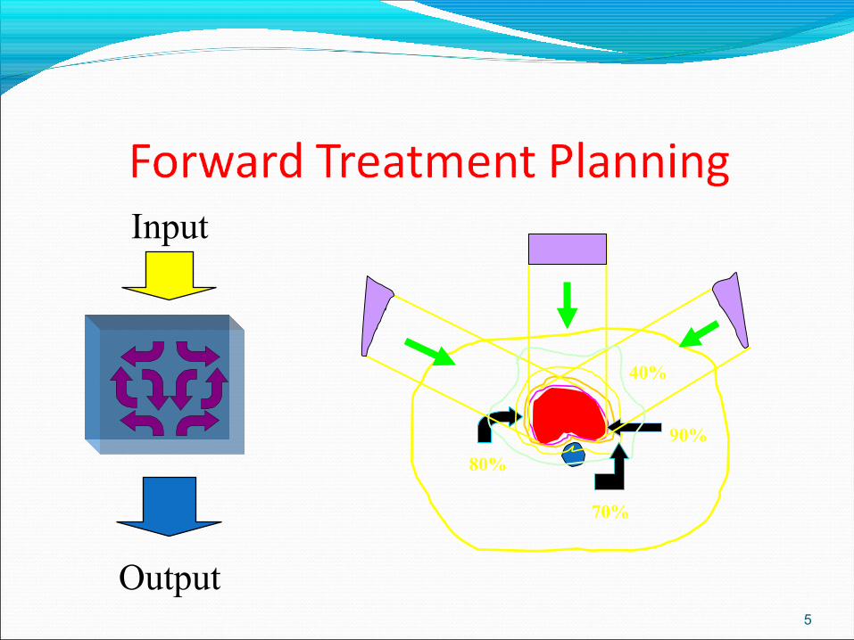
Forward Planning3D Conformal Therapy (not IMRT) is forward based
planning.
Planner chooses number and position of beams, shape, weighting and wedging, calculates the resulting distribution, & adjusts the beam parameters as needed
Dose to structures is NOT specified
3
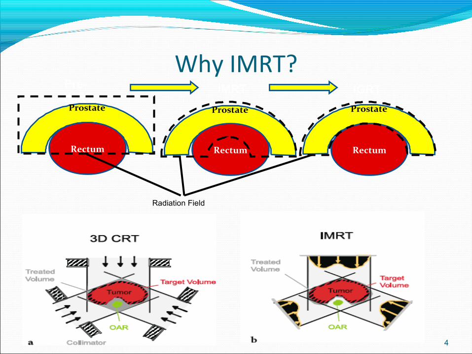
Why IMRT?
4
Radiation Field
Prostate
Rectum
Prostate
Rectum
Prostate
Rectum
Pre-IMRT
IMRT IGRT
5
70%
80%
90%
40%
Input
Output
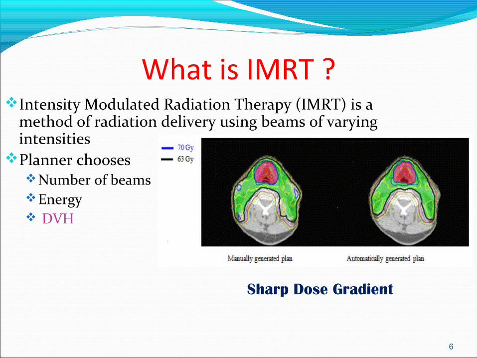
What is IMRT ?Intensity Modulated Radiation Therapy (IMRT) is a
method of radiation delivery using beams of varying intensities
Planner chooses Number of beams Energy DVH
6
Sharp Dose Gradient
7
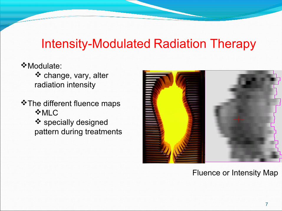
Intensity-Modulated Radiation Therapy
Modulate: change, vary, alter radiation intensity
The different fluence mapsMLC specially designed pattern during treatments
Fluence or Intensity Map
Work flow
CT SimulationTPS PlanningPlanning Approval Pre treatment quality AssurancePass or failPre treatment Image VerificationTreatment Delivery
8
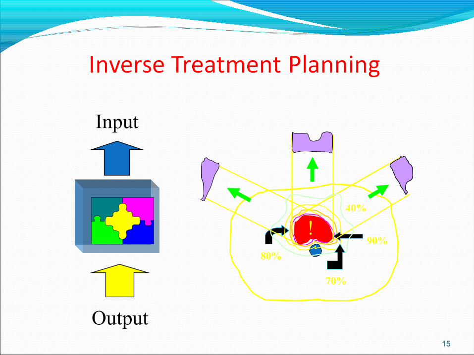
Inverse Planning
IMRT uses a different method of planning.
The final goal - in terms of Dose/Volume for each structure is defined at the outset.
The DVHs- Dose volume Histograms are adjusted to achieve the desired plan (rather than the beams)
9
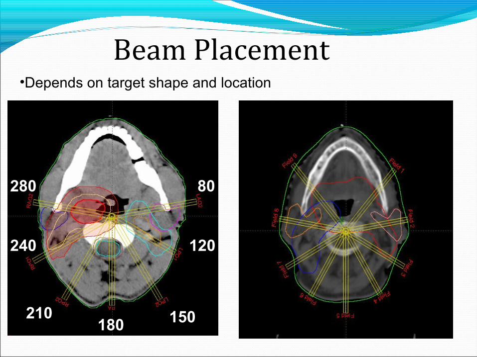
9 beams
80
120
150180210
240
280
7 beams
•Depends on target shape and location
Beam Placement
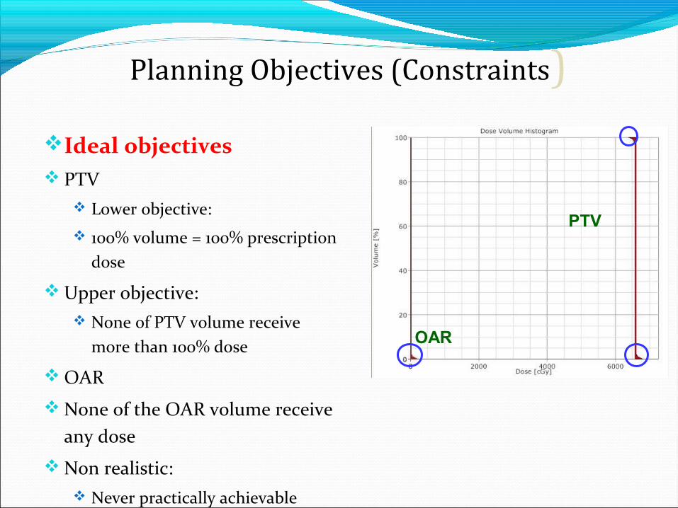
Ideal objectives PTV
Lower objective:
100% volume = 100% prescription dose
Upper objective: None of PTV volume receive
more than 100% dose
OAR
None of the OAR volume receive any dose
Non realistic: Never practically achievable
OAR
PTV
Planning Objectives (Constraints)
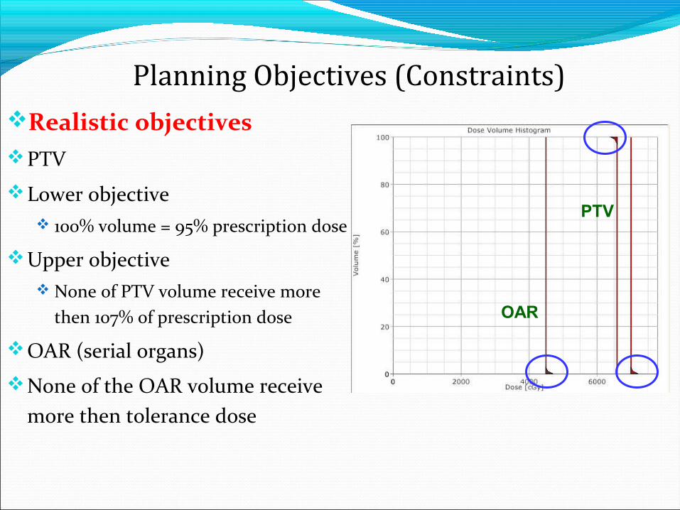
Realistic objectivesPTV
Lower objective 100% volume = 95% prescription dose
Upper objective None of PTV volume receive more
then 107% of prescription dose
OAR (serial organs)
None of the OAR volume receive more then tolerance dose
OAR
PTV
Planning Objectives (Constraints)
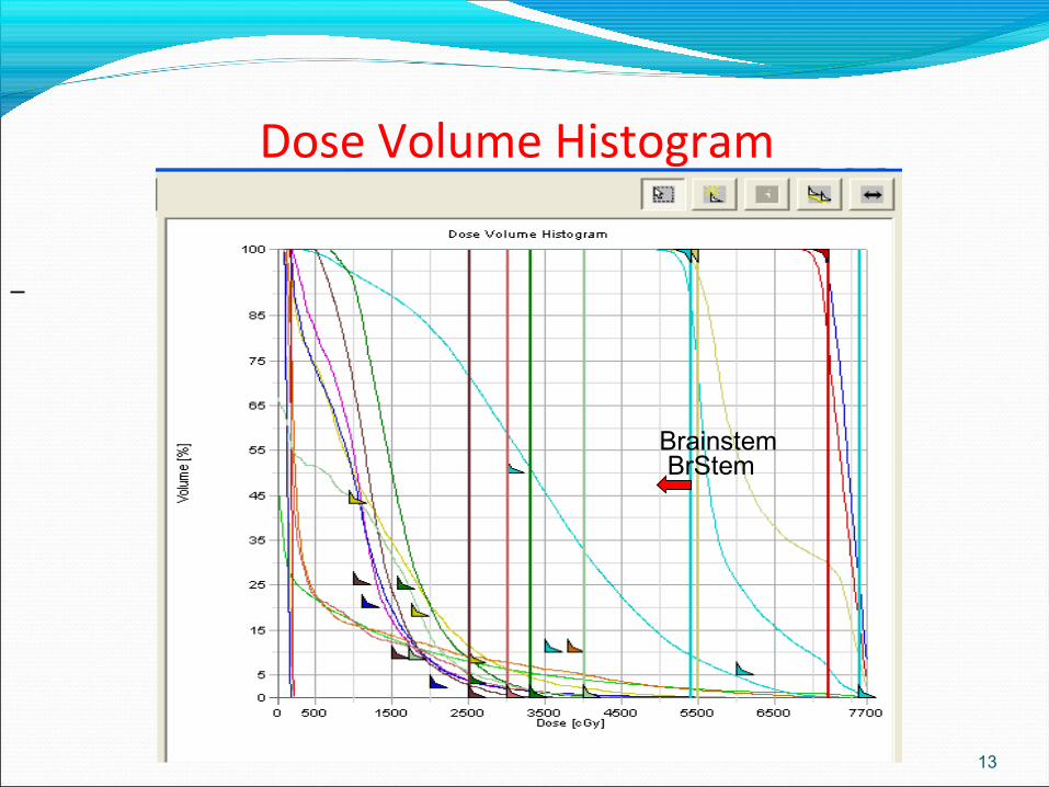
Dose Volume Histogram
13
BrainstemBrStem
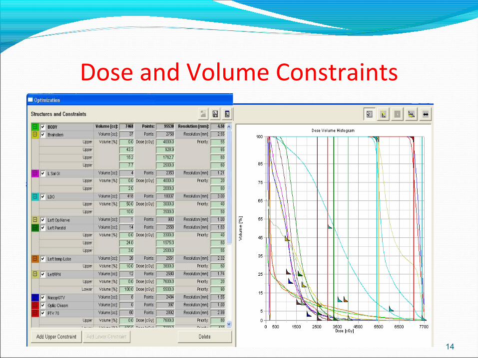
Dose and Volume Constraints
14
15
70%
80%
90%
40%
!
Input
Output
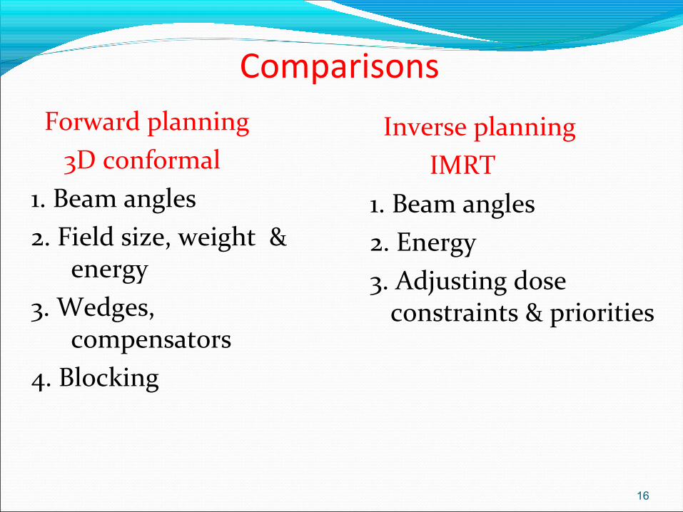
Comparisons Forward planning 3D conformal1. Beam angles2. Field size, weight &
energy3. Wedges,
compensators4. Blocking
Inverse planning IMRT1. Beam angles2. Energy3. Adjusting dose
constraints & priorities
16
Optimization
Process where many different flounces are tried, in order to find the best (optimum) one
17
18
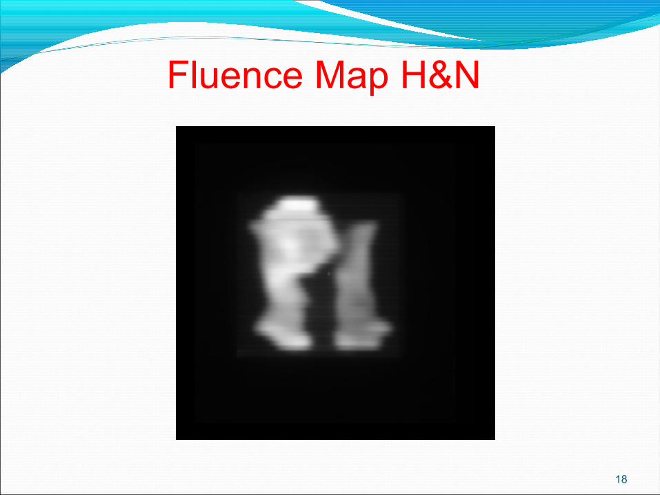
Fluence Map H&N
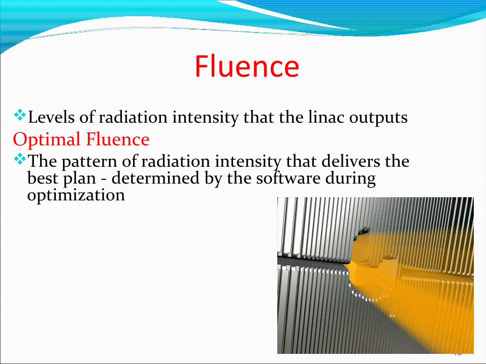
FluenceLevels of radiation intensity that the linac outputsOptimal FluenceThe pattern of radiation intensity that delivers the
best plan - determined by the software during optimization
19
Actual fluence What the treatment unit is able to deliver –
considering physical parameters of the mlc (max.leaf speed, leaf transmission etc.)
20
Optimization constraints
Define desired plan in terms of the Dose/Volume each structure can receive
Assign a priority to each point
21
Priorities
The priority is specified for each dose constraint points
It defines the importance of that point relative to all other points for all structures
22
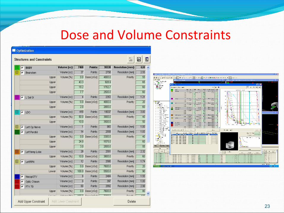
Dose and Volume Constraints
23
Iterations
The beam intensities are adjusted many times during optimization, and many ‘plans’ calculated
Each adjustment is 1 iteration
24
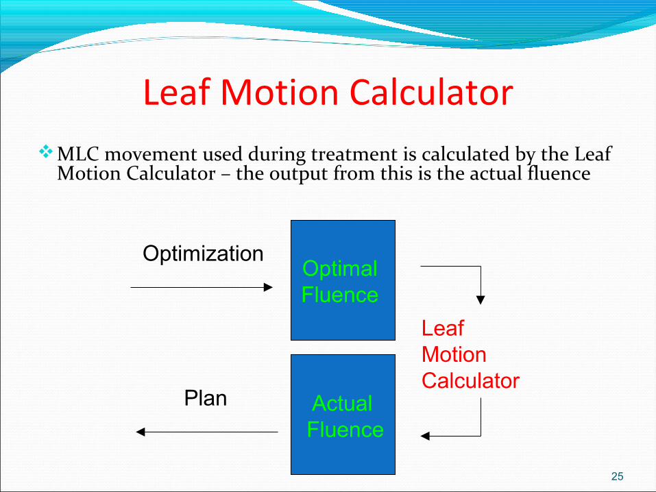
Leaf Motion CalculatorMLC movement used during treatment is calculated by the Leaf
Motion Calculator – the output from this is the actual fluence
25
Optimal Fluence
Leaf Motion Calculator
Actual Fluence
Optimization
Plan
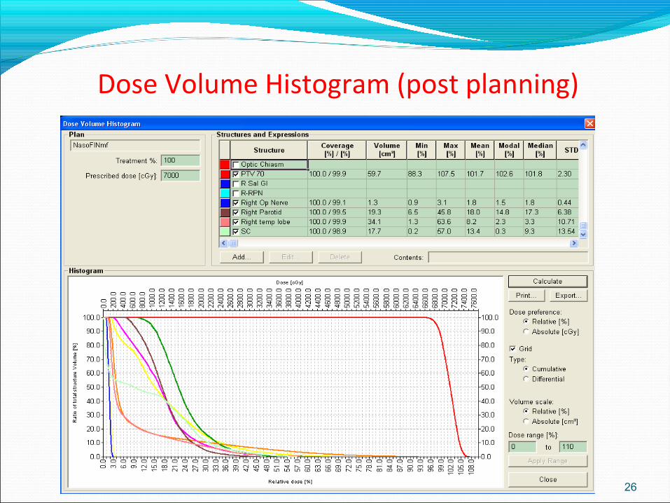
Dose Volume Histogram (post planning)
26
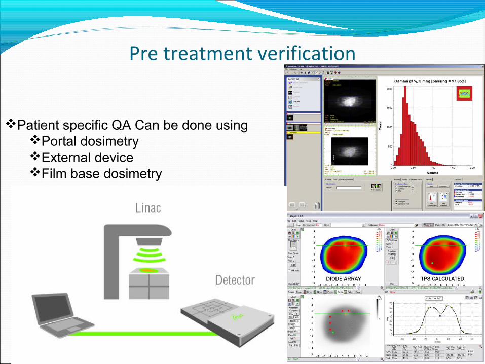
Pre treatment verification
27
Patient specific QA Can be done usingPortal dosimetryExternal deviceFilm base dosimetry
Delivery
2 main ways of delivering the treatment;1. Segmented Delivery Also described as Step and Shoot - the beam is OFF as the MLCs move to their next position
28
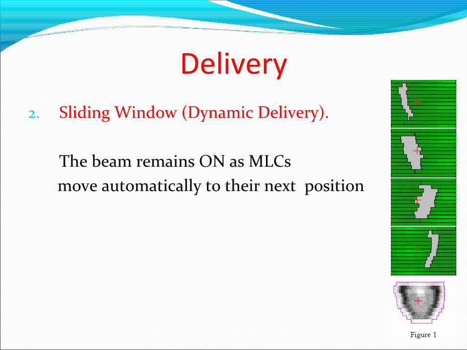
Delivery2. Sliding Window (Dynamic Delivery).
The beam remains ON as MLCs move automatically to their next position
29
Summary Forward planning IMRT Dose volume histogram Inverse planning Optimization Dose constraints Priorities Iterations Cost functions and penalties Fluence – actual and optimal Leaf motion calculator Segmented delivery Step and shoot
30
Take
home m
essag
e
I
MR
T i
s a
ll a
bo
ut
Vo
lum
es

31
Questions?Comments?