Embed Size (px)
Citation preview

CAD Project
Presenter : Dr. Dennis C Thomas
Guide : Dr. Arghya Deb sir

Acknowledgement
Our sincere thanks to :
Dr. Arghya Deb sir
CAD Lab Teaching Assistants

COMPUTATIONAL MODELLING OF INTERVERTEBRAL DISC USING ABAQUS
• Our project is to replicate a published research paper by J.S Tan et al .
• In this research paper , the lumbar segment was modelled using abaqus and the reaction to compressive forces and tortional forces studied .
AIM OF OUR PROJECT
• Is to create a model of the intervetebral disc and study its reaction to compressive forces.
• We have to plot the compressive force and the axial displacement and verify if it matches with the findings of other research papers

The findings of other research papers
Ref : Research paper by J.S Tanh et al

# X Y # X Y # X Y
1. 0 20 7. 15.56 17.58 13. 22.5 6.66
2. 2.73 20 8. 18.22 15.79 14. 22.5 5.0
3. 5.89 19.74 9. 20 13.5 15. 21.25 27
4. 10 19 10. 21.07 12.02 16. 20 1.25
5. 12.77 18.5 11. 21.8 10 17. 15 0
6. 14.14 17.56 12. 22.25 8.75 18. 0 0
The Nucleus Pulposus as Core was created using the
Following Co-ordinates as Approximates

Creation of Parts
• Nucleus Pulposus
• Annulus Fibrosis: Ground
subtance and Collagen layers
• 3 Collagen Layers in this case
• Two End Plates
• Upper and Lower Vertebra

Annulus Fibrosis

Nucleus Pulposus
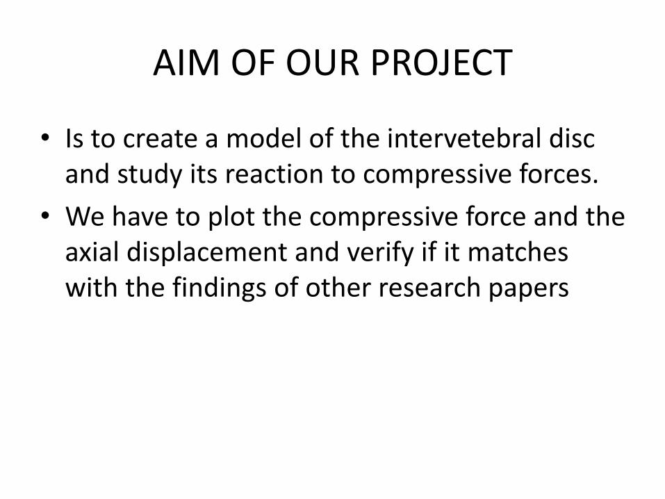
Vertebra

Collagen Layers

Assigning of Material Property
Collagen Endplates Ground Substance
Density Density Density
1000 1080 1000
Elastic Elastic Elastic
Young’s Modulus 45 Young’s Modulus 23.8 Young’s Modulus 4
Poissons Ratio 0.4 Poissons Ratio 0.4 Poissons Ratio 0.4

Assigning of Sections

Section 2 :Membrane(The thickness to be mentioned)

Creation of Step using Dynamic Explicit Method:: Time period = 1

History outputs
• 1 ) Integrated forces acting on a surface . The surface was chosen : The upper surface of the upper endplate.
• 2) Displacements of a node on the upper vertebra

Assembly of all Parts and Instant Creation (Mesh Dependent parts)

Interactions
• Interactions between
• Endplates and Nucleus pulposus
• Endplates and The Annulus Fibrosis

Interaction – 1

Interaction - 2

Interaction - 3

Interaction - 4

Constraints
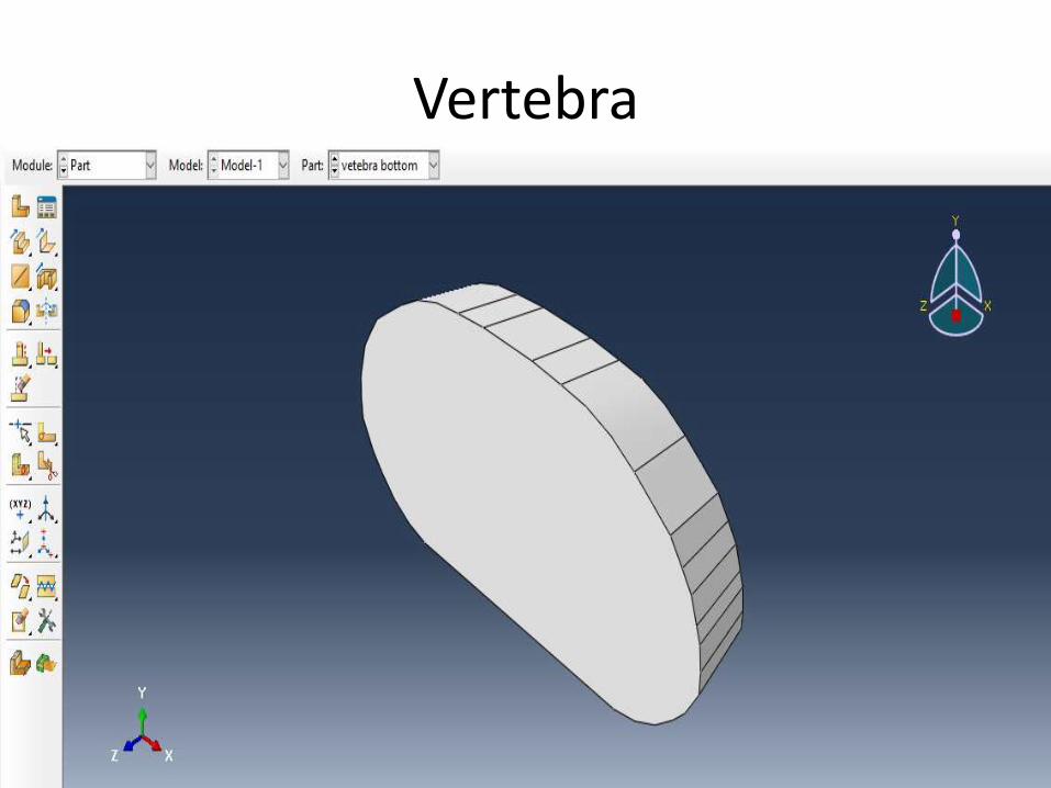
• Vertebra as Rigid Body
• Collagen shells embedded onto the Ground Substance of Annulus Fibrosis
• Tying of Endplates to the Vertebrae
• Annulus Fibrosis being tied to the Nucleus Pulposus
Constraint – 1 & 2

Constraint 3

Constraints 4&5

Constraint 6

Boundary Conditions
• For Upper and Lower Vertebrae

Boundary Condition 1
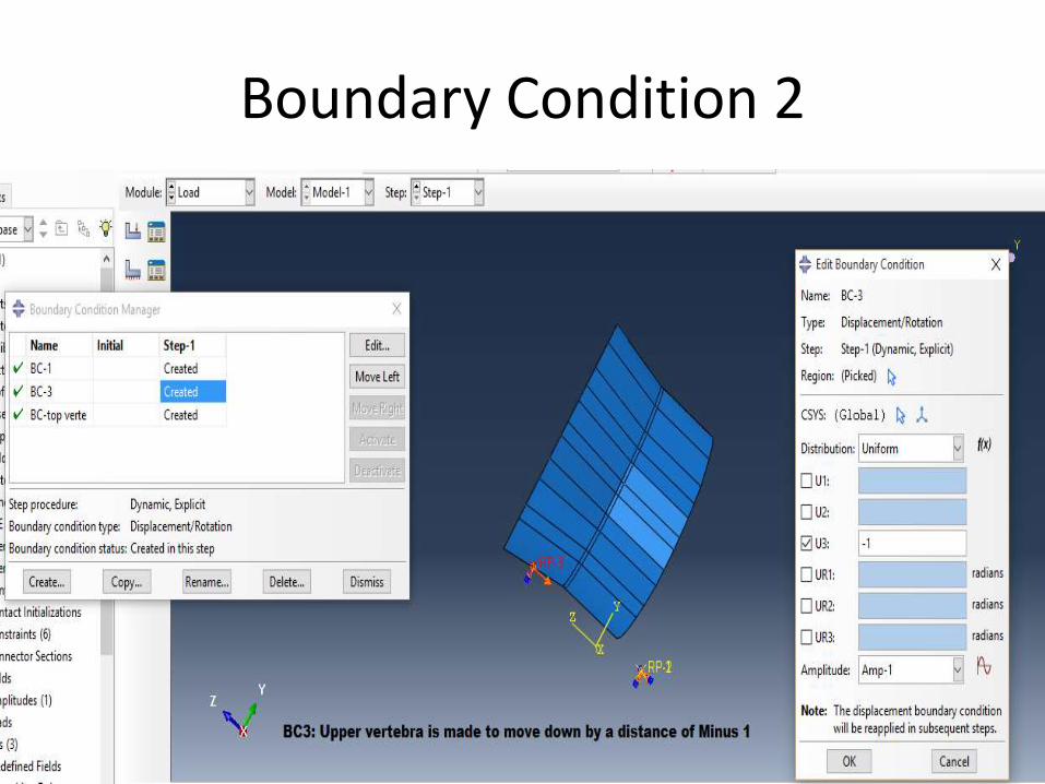
Boundary Condition 2

Meshing of Rigid Body and Rest of the Structures

The job was run and the results obtained

• The history outputs namely
• The Force acting on our integrated surface
• The Displacement of our Node (on the vertebral body) were plotted
• These two plots were saved in the X-Y Data . Using the option of combine (x,x) :
• The two plots were merged to give the plot between Compressive force and Axial displacement

Graph between time and displacement
X axis: Time Y axis: Displacement (in mm)
0.0 0.1 0.2 0.3 0.4 0.5 0.6 0. 7 0.8 0.9 1.0

Graph between Compressive force and axial displacement
X Axis: Axial displacement (in mm)Y Axis: Axial Compressive Force

Graph between Compressive force and axial displacement
X Axis: Axial displacement (in mm)Y Axis: Axial Compressive Force ( in 1*E3)

CONCLUSION
Other research papers Our model

Conclusion
• The plot of the compressive force with the axial displacement was studied .
• It was found that the nucleus pulposus and the annulus do play an important role .
• The graph obtained is comparable to other researchers findings .

THANK YOU


![Use of Nonlinear Finite Element Analysis of Bone Density ... · vertebral endplates by osteoporosis may cause cage subsidence [7, 8]. Finite element analysis (FEA) is one technique](https://img.pdfslide.us/doc/110x75/5fdcada2a4629e48cf5c8b27/use-of-nonlinear-finite-element-analysis-of-bone-density-vertebral-endplates.jpg)