Embed Size (px)
Citation preview

Dr. SHEFALI B. MESHRAM

Xeroradiography is the production of visible image utilizing the charged surface of a photoconductor (amorphous selenium) as the detecting medium, partially dissipating the charge by exposure to X rays to form a latent image and making the latent image visible by xerographic processing.

PHOTOCONDUCTION The valance band is the highest energy band in which
electrons normally exist at a very low temperature.
The next highest permissible band is called the conduction band.
These two bands are separated by a forbidden gap.

EN
ER
GY
CONDUCTION BAND
VALENCE BAND
FORBIDDEN ENERGY GAP

Solids that have many electrons in the conduction level are known as conductors. Conductors do not have forbidden region.
In insulators the forbidden gap is so large that electrons seldom absorb enough energy to bridge the gap.
A semiconductor is a solid that contains a small forbidden gap. Addition of appropriate quantity of energy will allow some electrons to bridge the forbidden gap and enter the conduction band.

In photoconductor, this energy is provided by absorption of visible electromagnetic radiation (light).
Photoconductors are a special type of semiconductors.
In Xeroradiography, the photoconductor used is selenium.

When electron leaves the valence band, the area of absent negative charge is known as positive hole. Thus a electron- hole pair is created. When they are subjected to an electric field, the two members of the pair migrate in opposite direction.

XERORADIOGRAPHIC PLATE It is a sheet of aluminum approximately 9 ½ x 14
inches in size on which a layer of amorphous selenium has been deposited. There is an interface layer between the selenium and the aluminum and an over coating protecting the selenium layer.

XERORADIOGRAPHIC PLATE 0.1 µ OVERCOATING
150 or 320 µ SELENIUM
0.1 µ INTERFACE
2 mm ALUMINUM

ALUMINIUM SUBSTRATE The aluminum plate on which selenium is deposited is
made up of meticulously cleaned aluminum with an exceedingly smooth surface.

INTERFACE LAYER Heat treatment of aluminum substrate serves to form a
thin layer of aluminum oxide.
Although aluminum is a conductor, aluminum oxide is an insulator.
The purpose of interface is to prevent negative charges induced in the aluminum from migrating into selenium and dissipating the positive charge induced on the selenium surface.

SELENIUM COATING Highly purified selenium in the amorphous (vitreous
form) is deposited onto the aluminum substrate by condensation of vaporized liquid selenium in a high vacuum.
The thickness of selenium layer is 150µ for powder toner development while it is 320µ for liquid toner development plates.

PROTECTIVE OVERCOATING Cellulose acetate is used . It is applied by dip- coating
from solution to form about 0.1µ thick layer.
It bonds well with selenium.
It has high resistance enough to prevent lateral conduction of charges, which would degrade the electrostatic latent image.
It extends the life of Xeroradiographic plate by a factor
of about 10.

Steps involved in Xeroradiographic imaging process.
A uniform charge is deposited onto the surface of selenium. This sensitizes the plate before exposure to x-rays.
This charged plate is placed in a light tight cassette and is exposed to x rays just like a film screen cassette. The x rays reaching the plate cause the photoconductor layer to lose its charge in an amount corresponding to the intensity of x ray beam. The uniform charge is thus dissipated, and the remaining charge pattern forms the latent electrostatic image.

This latent electrostatic image is then developed by exposing the surface of the plate to fine charged particles called toner that are attracted to the plate surface in proportion to the intensity of the remaining charge.
The toner image is transferred to a receiver sheet by an electrostatic process. It is fixed to the sheet to make a permanent record.
The plate is then cleaned of all the remaining toner and prepared for reuse.

PHOTOCONDUCTIVE LAYER Three properties required by the photoconductor to be
used in Xeroradiography are.
1. The electrical conductivity in the dark must be that of a good insulator so that a charge pattern present on the surface will be retained long enough to complete the steps of development.
2. The material must become electrically conducting during exposure to X rays so that an electrostatic image can be formed on its surface by the exposure .
3. It must have mechanical properties of durability and ease of fabrication

The most stable form of selenium is its crystalline form. It is not used in Xeroradiography because it has relatively high electrical conductivity.
The amorphous form is a super cooled form of liquid selenium. It is formed by cooling the liquid suddenly so that crystals do not have time to form. It is deposited onto the aluminum plate by condensation of vaporized liquid selenium in a high vacuum.

Pure amorphous selenium is mandatory as the presence of any impurity increases the dark decay rate. Dark decay rate is the reduction in plate voltage while it remains in darkness.

PLATE CHARGING The first step in the Xeroradiographic process is to
sensitize the photoconductor by applying a uniform electrostatic charge to its surface in the dark.
Because selenium is an insulator in the dark, during charging, the xeroradiograhic plate can be considered to be a parallel plate capacitor in which the outer layer of selenium surface and the aluminum backing (substrate) acts as parallel plates and the selenium itself acts as dielectric.

A capacitor or condenser consists of two sheets of conducting material with a sheet of insulating material between them . One plate is charged positive and the other is negative. So a potential difference or voltage exists between the two plates. The insulator material in between is known as dielectric.


If a positive charge is deposited on the surface of selenium, the remainder of the selenium atoms are distorted into the configuration of induced dipoles. The negative pole of each atom are attracted towards the positive charge, causing the atomic layer adjacent to the aluminum substrate to present a positive charge at the selenium- aluminum interface.

Polarization of the selenium atoms will attract negative charges in the aluminum substrate towards the back of selenium layer. In other words negative charge has been induced in the aluminum substrate by the presence of positive charge on the surface of selenium.
The interface layer reduces the negative charge leakage from the substrate into the selenium.

DIELECTRIC

The device used to produce a charge on the surface of the selenium operates on the principle of corona discharge.
If a sufficiently high potential difference called corona threshold voltage is applied between a fine wire and ground, the air near the wire becomes ionized.
If the voltage is positive, the free electrons of the gas near the wire will move towards the wire. These electrons will be of high energy and instead of going straight to the wire, they will interact with many molecules or atoms in the air and create many additional ions.

The positive ions thus created will move away from the wire.
This movement of ions is called corona current.
When such a wire is placed near the surface of Xeroradiographic plate, some positive ions repelled from the wire will be deposited on the surface of the plate.

EXPOSURE OF CHARGED PLATE After the plate is sensitized by corona charging it must
be enclosed in a cassette that is light tight and rigid enough to provide mechanical protection for the fragile plate.
Exposure to Xray.
electron- hole pairs.
electrons migrate to plate surface and discharge the positive charge originally laid down.

the positive holes migrate through the selenium toward the substrate, where they are neutralized by the induced negative charge.
The amount of discharge of the positive charge is proportional to the intensity of Xrays that penetrate the patient.
The remaining charge pattern on the plate surface is called electrostatic latent image.

CONDUCTIVITY INDUCED BY THE XRAY The energy gap between valence band and conduction
band of amorphous selenium is 2.3 eV which corresponds to a wavelength of about 5400 A ( visible light in the range of green- yellow).

Photoconductivity induced by Xrays and that by light differ in two important ways,.
1. The Xray photons can penetrate further into the selenium and their absorption may be uniform throughout the selenium layer.
2. The energy of Xray photon is transferred to a photoelectron or a recoil electron and each of these electrons will usually have enough kinetic energy to produce many more charged carriers (electron- hole pairs) along its tract.

ELECTRIC FIELD DISTRIBUTION ABOVE LATENT IMAGE
++++++++++++++++++

++++++

++++++
-_-=======-_
-_-==========----------_

XERORADIOGRAPHIC UNDERCUTTING Caused by ionisation of the air in the space between
the selenium surface and the lid of the cassette.
Ionisation may be caused by interaction of Xrays directly with air molecules or it may be caused by high speed electrons being able to escape from the selenium and enter the air space.

XERORADIOGRAPHIC UNDERCUTTING
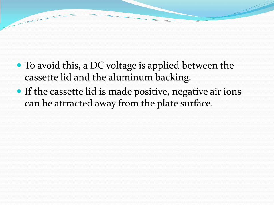
To avoid this, a DC voltage is applied between the cassette lid and the aluminum backing.
If the cassette lid is made positive, negative air ions can be attracted away from the plate surface.

POWDER DEVELOPMENT Development consists of attracting small charged
particles called toner to the electrostatic latent image.
The toner used is a pigmented thermoplastic material of average diameter 4 µ.
The powder cloud development or the aerosol development is fast, simple and it provides edge enhancement.
The exposed plate is placed on top of a dark box into which an aerosol of charged toner particles is sprayed through a nozzle.


Aerosol is created when a pressurized gas ( usually nitrogen) is used to force toner through small bore tube.
An aerosol is a suspension of small liquid or solid particles in a gaseous medium. They have random movements.
Agglomeration of toner particles into large particles is prevented as turbulent flow is produced when aerosol is passed through a small bore nozzle.
The electric charge on the toner particle is produced by friction between the toner and the nozzle wall.
Both positive and negative charges are produced. POSITIVE DEVELOPMENT involves attracting negatively
charged toner particles to the remaining positive charge on the surface of selenium.

To get positive development, positive voltage is applied to the aluminum backing to attract only negatively charged particles.
There are now two electrostatic forces influencing the motion of the particles; the uniform electric field of the back-bias voltage and the non-uniform field created by latent image.
For typical positive development, the back-bias potential is in the range of 2000V DC.
With positive development, unexposed or minimally exposed areas of the plate will be dark blue. ( calcification will appear as blue).

POSITIVE DEVELOPMENT.

NEGATIVE DEVELOPMENT.

LIQUID DEVELOPMENT Liquid toner particles are black. The particle size of is 1.7 µ (blue powder toner – 4µ). Also they have smaller charge per particle ( 150 elementary
charge per particle, while in powder toner it is 1000 elementary charge per particle).
Smaller particle plus less charge on each particle results in more toner particles being deposited per image on the imaging plate.
Cancelling all the charge on the plate may mean that toner particles have to be stacked several layers deep on the plate.
Toner particles stacked on top of each other will increase optical density in the final image recorded.


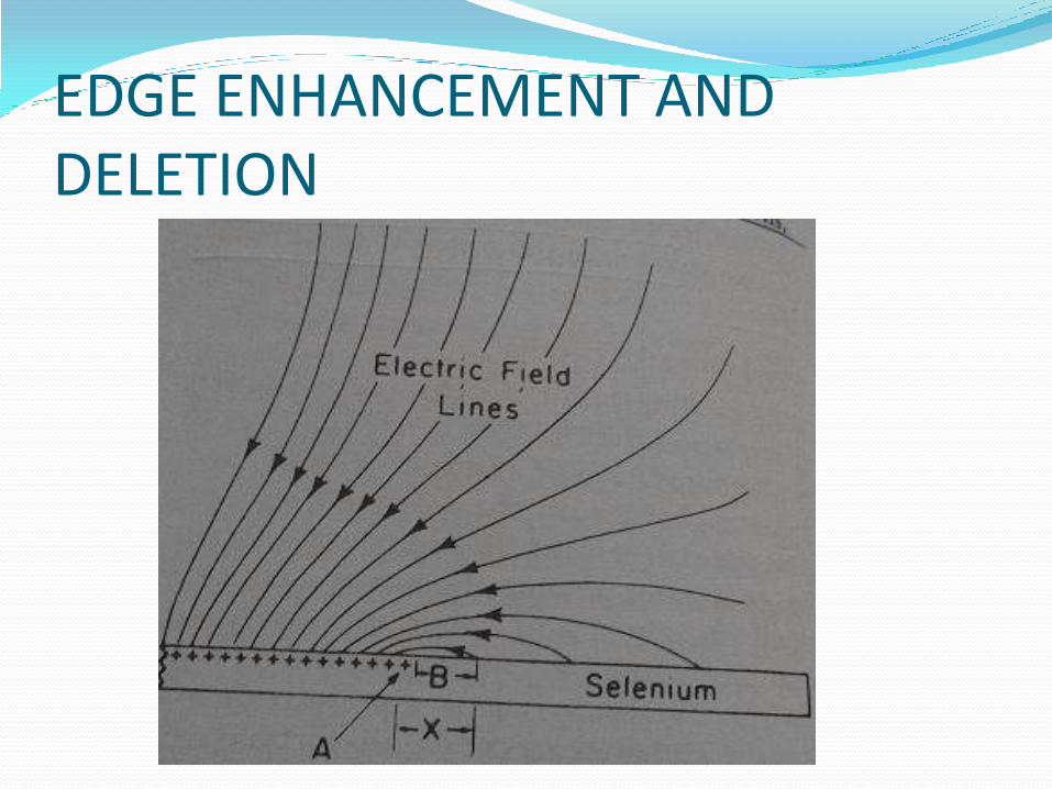
EDGE ENHANCEMENT AND DELETION

There is a relationship between edge
enhancement, plate voltage, back-bias voltage
and size of deletions.
CONTRAST DELETION
WIDTH
HIGH BACK BIAS
LOW SMALL
HIGH PLATE VOLTAGE
HIGH LARGE

IMAGE TRANSFER AND FIXING The image on the surface of Xeroradiographic plate is
then transferred to paper and fixed to form a permanent image.
A electrostatic transfer process is used.
The paper is coated with a slightly deformable layer of plastic, such as a low molecular weight polyethylene material.
When this paper is pushed against the powder image under relatively high pressure, the toner particles get embedded into it.

After the image is transferred, the paper is peeled off the plate and the loosely held powder image is made into a permanent bonded image by heating the paper to about 475˚ F.
The heat softens the plastic coating on the paper and allows the toner particles to sink into and become bonded to the plastic.

PLATE CLEANING All toner must be removed before the plate is to be
reused .
The plate is exposed to a light source (electroluminescent strip) that reduces the bond holding the residual toner to the plate.
A preclean corotron exposes the plate to an alternating current that serves to neutralize the electrostatic forces holding toner to the plate.
A cleaning brush then mechanically brushes the residual toner from the plate.

RELAXATION To prevent faint ghost images.
Absorption of X-rays in the selenium produces an alteration in the physical property of selenium that causes some photoconductivity to persist for as long as several hours after exposure.
If the plate were charged for a new exposure without allowing it to rest, a ghost image of the previous exposure will appear on development.
This rest period can be reduced to 2-3 min if the plate is relaxed by heating it to 140˚F for 150 sec.

STORAGE The cleaned and relaxed plate is then held in the
storage compartment at 89˚ F until needed for another exposure.

ADVANTAGES: Pronounced edge enhancement.
Choice of positive and negative display.
Good detail.
No need of silver halide coated film.
DISADVANTAGE: High radiation exposure.


THANK YOU.