Embed Size (px)
Citation preview
Spine Radiography
DR. MUHAMMAD BIN ZULFIQAR
PGR II FCPS SHL/SIMS
Spine Radiography
• Cervical Spine
• Thoracolumber Spine
Cervical Spine Radiography
• Clinical considerations are particularly important
because
– normal C-spine X-rays cannot exclude significant injury
– a missed C-spine fracture can lead to death
– life long neurological deficit.
• Clinico-radiological assessment of spinal injuries should be managed by experienced clinicians .
• Imaging should not delay resuscitation.
Cervical Spine Radiography
• CT or MRI is often appropriate in the context of a
– high risk injury,
– neurological deficit,
– limited clinical examination, or
– where there are unclear X-ray findings.
Cervical Spine Radiograph
Standard View:
– Anteroposterior view
– Lateral View
– Odontoid (Open Mouth View)
Extended View
– Swimmers View: when lateral radiograph fails to show vertebrae down to T1
Cervical Spine Systemic Approach
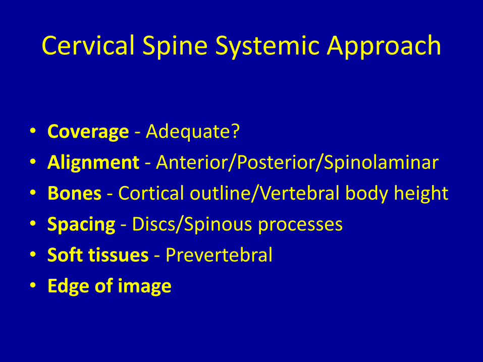
• Coverage - Adequate?
• Alignment - Anterior/Posterior/Spinolaminar
• Bones - Cortical outline/Vertebral body height
• Spacing - Discs/Spinous processes
• Soft tissues - Prevertebral
• Edge of image
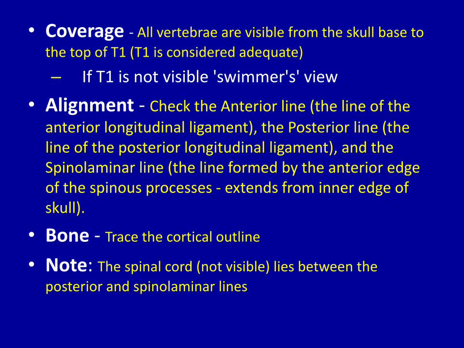
• Coverage - All vertebrae are visible from the skull base to
the top of T1 (T1 is considered adequate)
– If T1 is not visible 'swimmer's' view
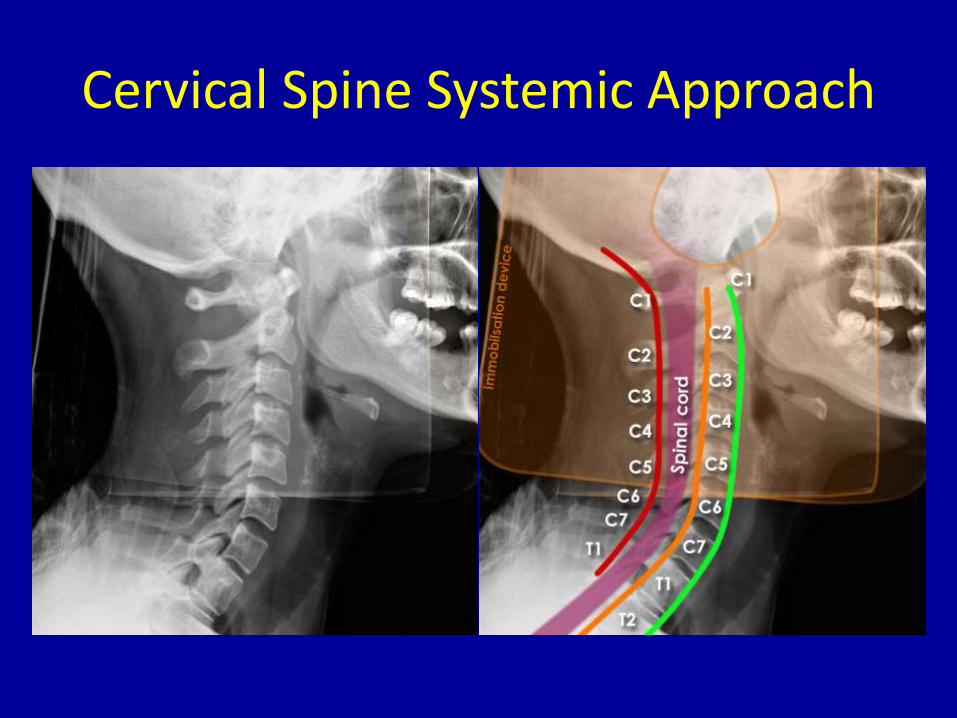
• Alignment - Check the Anterior line (the line of the
anterior longitudinal ligament), the Posterior line (the line of the posterior longitudinal ligament), and the Spinolaminar line (the line formed by the anterior edge of the spinous processes - extends from inner edge of skull).
• Bone - Trace the cortical outline
• Note: The spinal cord (not visible) lies between the
posterior and spinolaminar lines
Cervical Spine Systemic Approach
Cervical Spine Systemic Approach
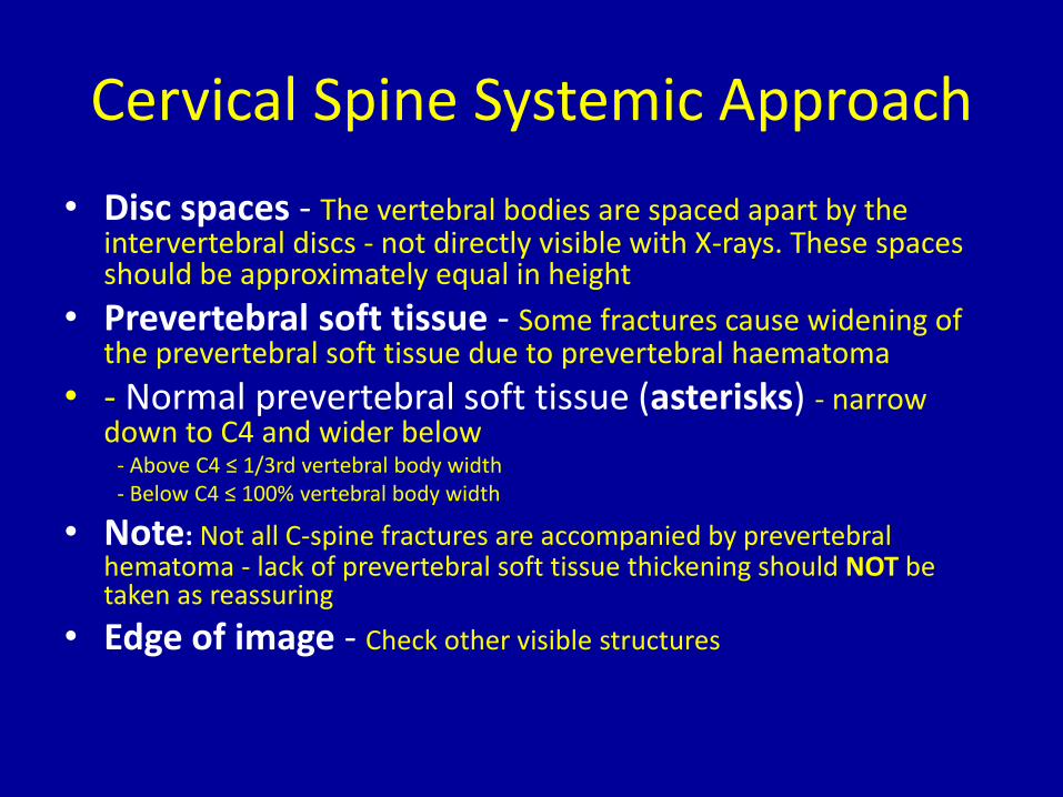
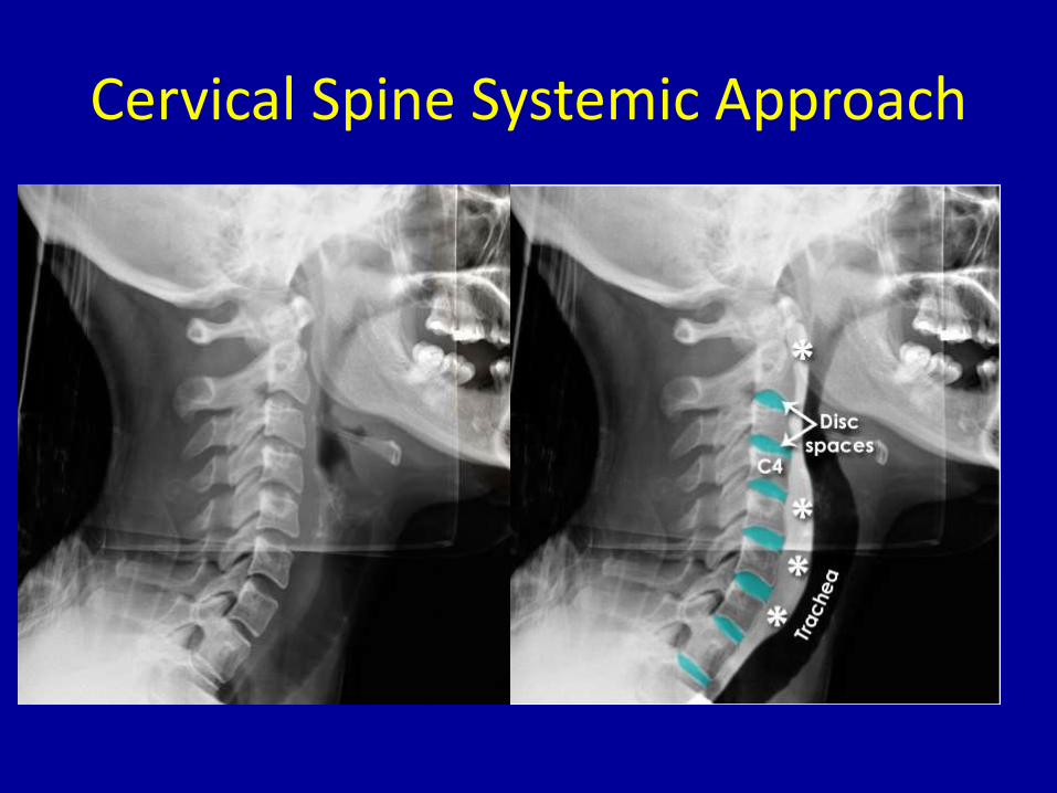
• Disc spaces - The vertebral bodies are spaced apart by the intervertebral discs - not directly visible with X-rays. These spaces should be approximately equal in height
• Prevertebral soft tissue - Some fractures cause widening of the prevertebral soft tissue due to prevertebral haematoma
• - Normal prevertebral soft tissue (asterisks) - narrow down to C4 and wider below
- Above C4 ≤ 1/3rd vertebral body width- Below C4 ≤ 100% vertebral body width
• Note: Not all C-spine fractures are accompanied by prevertebral hematoma - lack of prevertebral soft tissue thickening should NOT be taken as reassuring
• Edge of image - Check other visible structures
Cervical Spine Systemic Approach
Cervical Spine Systemic Approach
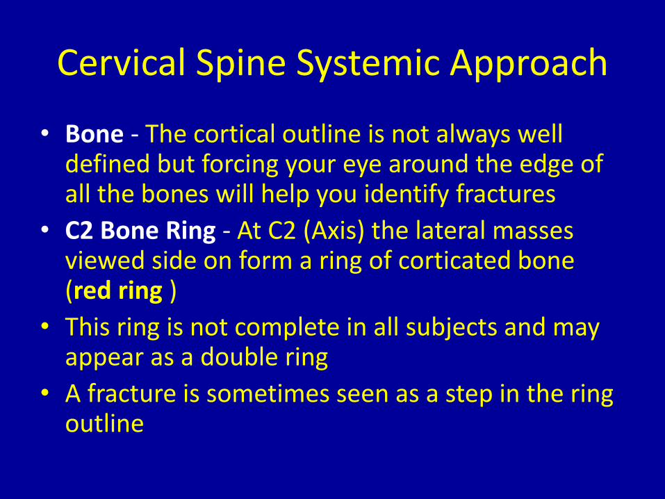
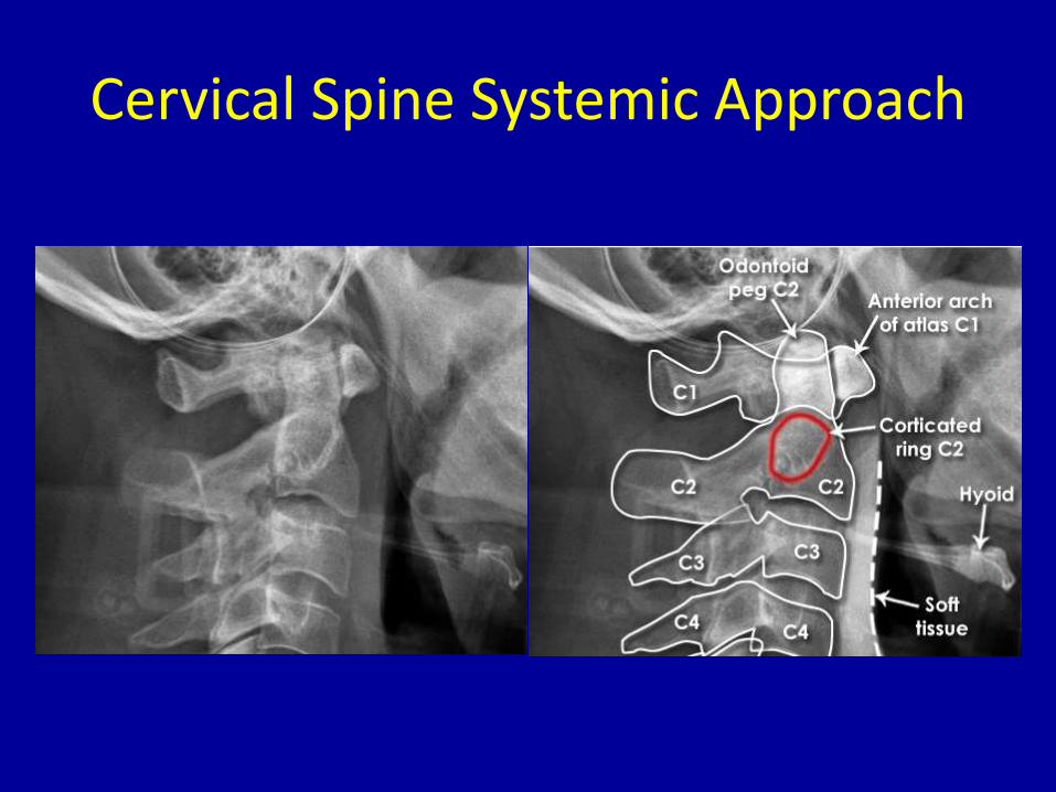
• Bone - The cortical outline is not always well defined but forcing your eye around the edge of all the bones will help you identify fractures
• C2 Bone Ring - At C2 (Axis) the lateral masses viewed side on form a ring of corticated bone (red ring )
• This ring is not complete in all subjects and may appear as a double ring
• A fracture is sometimes seen as a step in the ring outline
Cervical Spine Systemic Approach
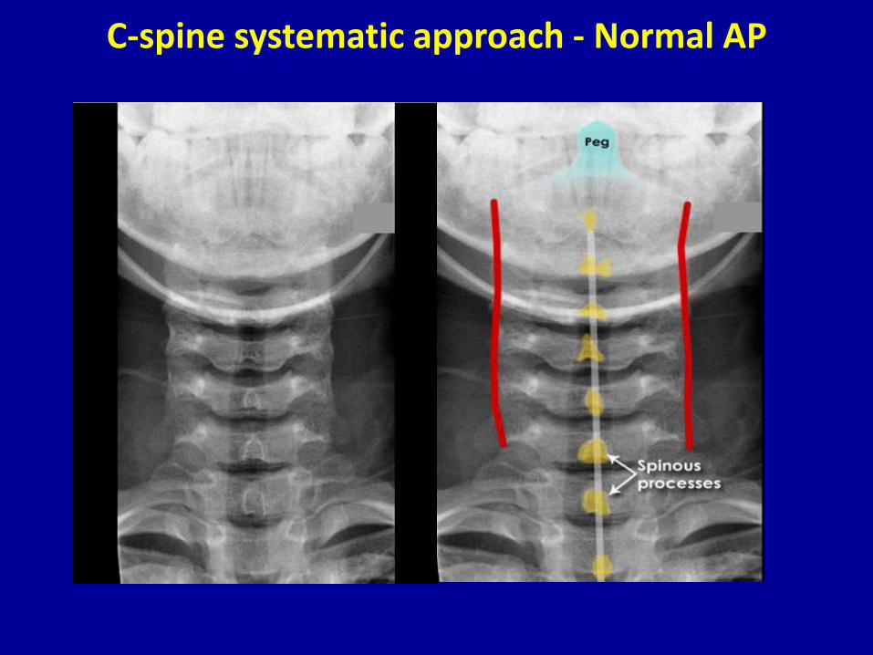
C-spine systematic approach - Normal AP
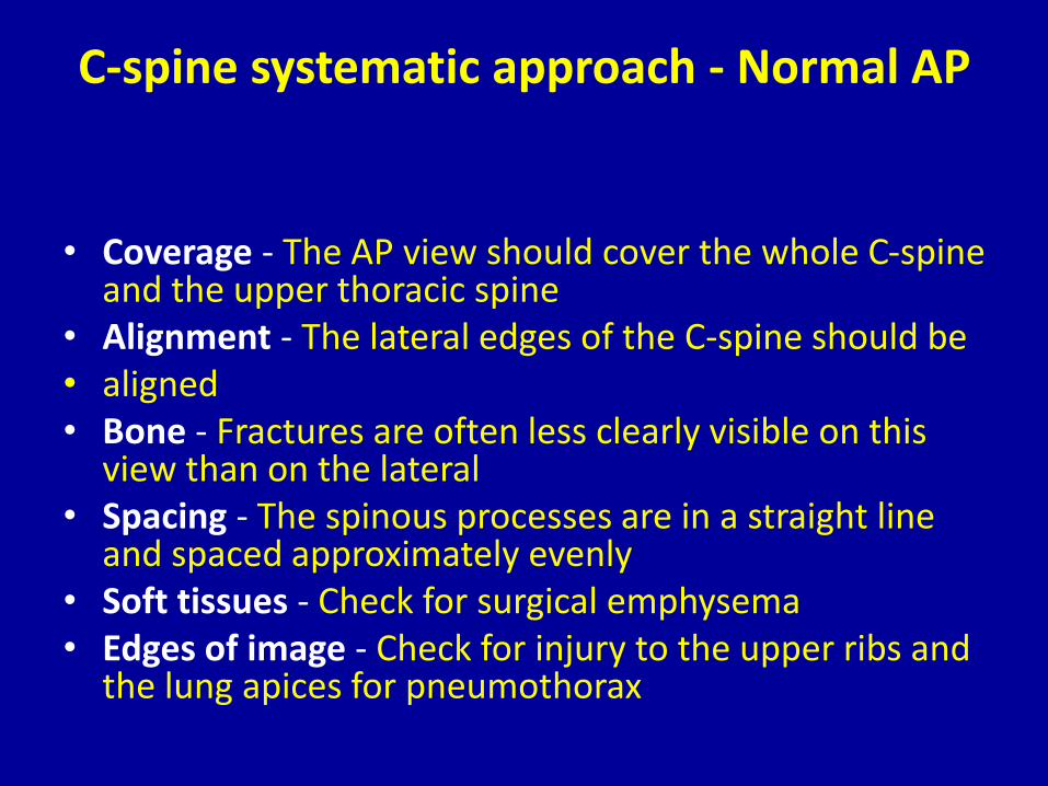
• Coverage - The AP view should cover the whole C-spine and the upper thoracic spine
• Alignment - The lateral edges of the C-spine should be• aligned • Bone - Fractures are often less clearly visible on this
view than on the lateral• Spacing - The spinous processes are in a straight line
and spaced approximately evenly• Soft tissues - Check for surgical emphysema• Edges of image - Check for injury to the upper ribs and
the lung apices for pneumothorax
C-spine systematic approach - Normal AP
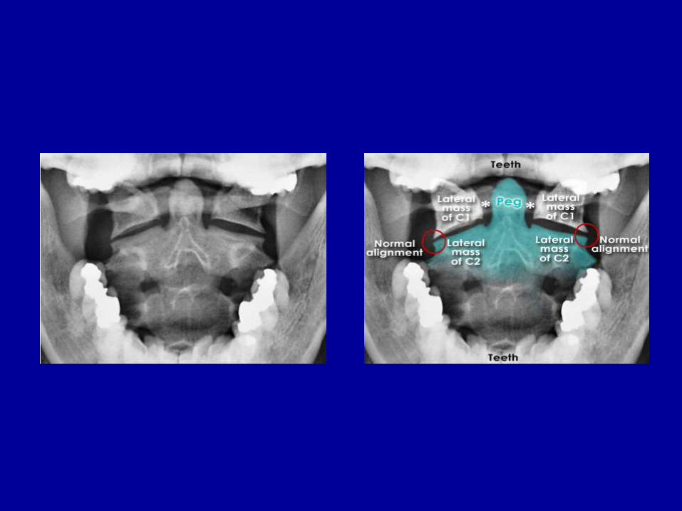
C-spine normal anatomy - Open mouth view
• This view is considered adequate if it shows the alignment of the lateral processes of C1 and C2
• The distance between the peg and the lateral masses of C1 should be equal on each side
• Note: In this image the odontoid peg is fully visible which is not often achievable in the context of trauma due to difficulty in patient positioning
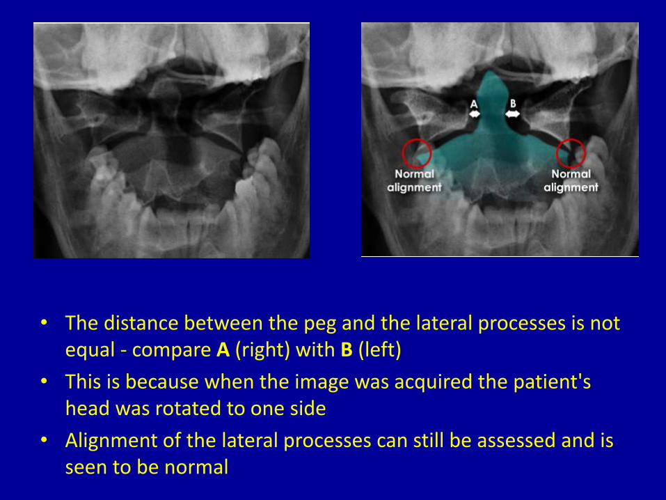
• The distance between the peg and the lateral processes is not equal - compare A (right) with B (left)
• This is because when the image was acquired the patient's head was rotated to one side
• Alignment of the lateral processes can still be assessed and is seen to be normal
Swimmer's' view
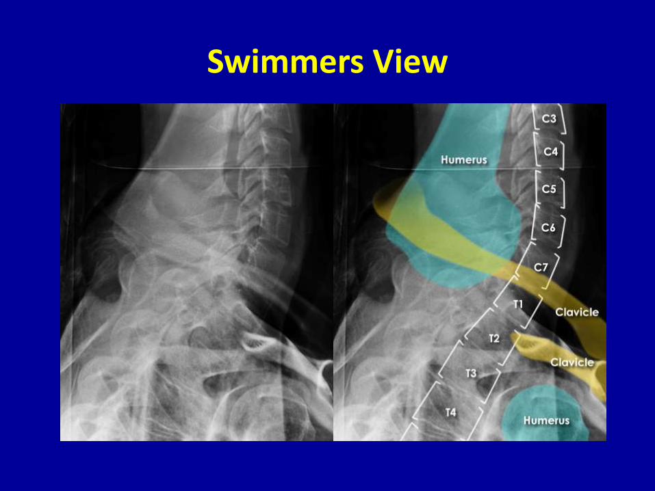
• This is an oblique view which projects the humeral heads away from the C-spine. A swimmer's view may be useful in assessing alignment at the cervico-thoracic junction if C7/T1 has not been adequately viewed on the lateral image, or on a repeated lateral image with the shoulders lowered.
• The view is difficult to achieve, and often difficult to interpret. If plain X-ray imaging of the cervico-thoracic junction is limited then CT may be required.
Swimmers View
Thoracolumber spine
• In the context of trauma similar principles apply to imaging both the Thoracic spine (T-spine) and the Lumbar spine (L-spine).
Thoracolumber spine
• Use a systematic approach
• Correlate radiological findings with the clinical features
• If 'instability' is suspected then further imaging with CT should
be considered
• If you see one fracture - check for another
Thoracic spine - Standard views
• AP and Lateral - Assess both views systematically .
• Images of the thoracic and lumbar spine are often large and the bones should be scrutinized in detail
• Note: The upper T-spine may not be visible on the lateral view - if injury is suspected here then a swimmer's view may be helpful
Thoracolumbar spine - Systematic approach
• Coverage - Adequate?
• Alignment - Anterior/Posterior/Lateral
• Bones - Cortical outline/Vertebral body height
• Spacing - Discs/Spinous processes/Pedicles
• Soft tissues - Paravertebral
• Edge of image
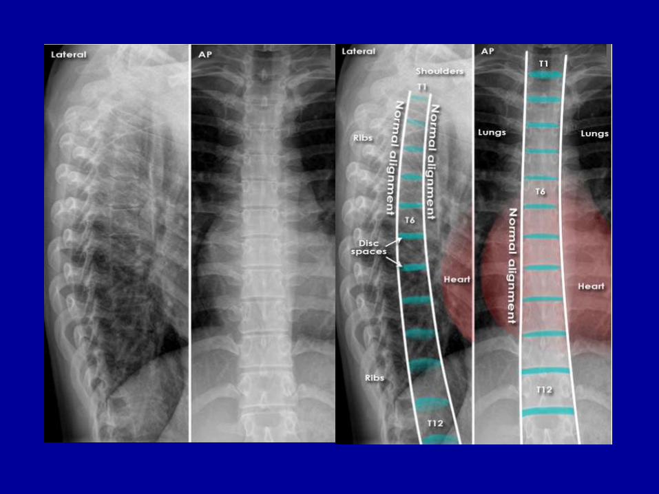
Thoracolumbar spine - Systematic approach
• Lateral and AP
• Coverage - The whole spine is visible on both views
• Alignment - Follow the corners of the vertebral bodies from one
level to the next
• Bones - The vertebral bodies should gradually increase in size
from top to bottom
Thoracolumbar spine - Systematic approach
• Spacing - Disc spaces gradually increase from superior to inferior - Note: Due to magnification and spine curvature the vertebral bodies and discs at the edges of the image can appear larger than those in the centre of the image
• Soft tissues - Check the paravertebral line (see AP image below)
• Edge of image - Check the other structures visible
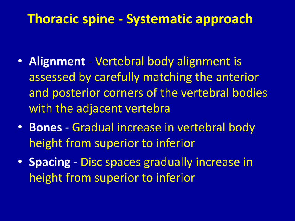
Thoracic spine - Systematic approach
• Alignment - Vertebral body alignment is assessed by carefully matching the anterior and posterior corners of the vertebral bodies with the adjacent vertebra
• Bones - Gradual increase in vertebral body height from superior to inferior
• Spacing - Disc spaces gradually increase in height from superior to inferior
VB = Vertebral bodyP = PedicleSP = Spinous process (ribs overlying)F = Spinal nerve exit foramen
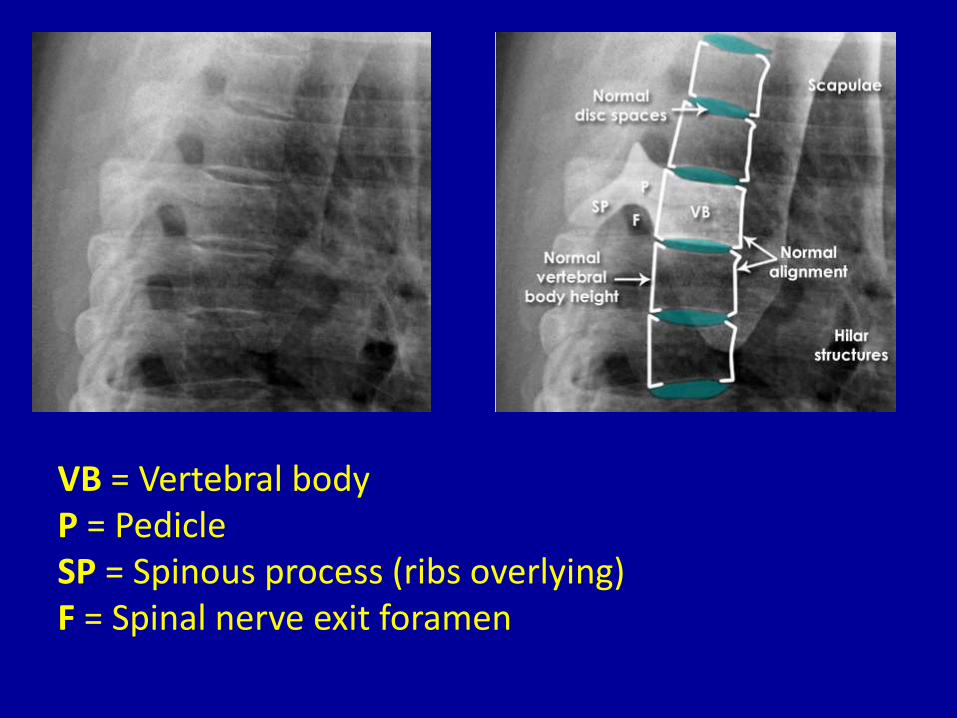
Thoracic spine - Systematic approach
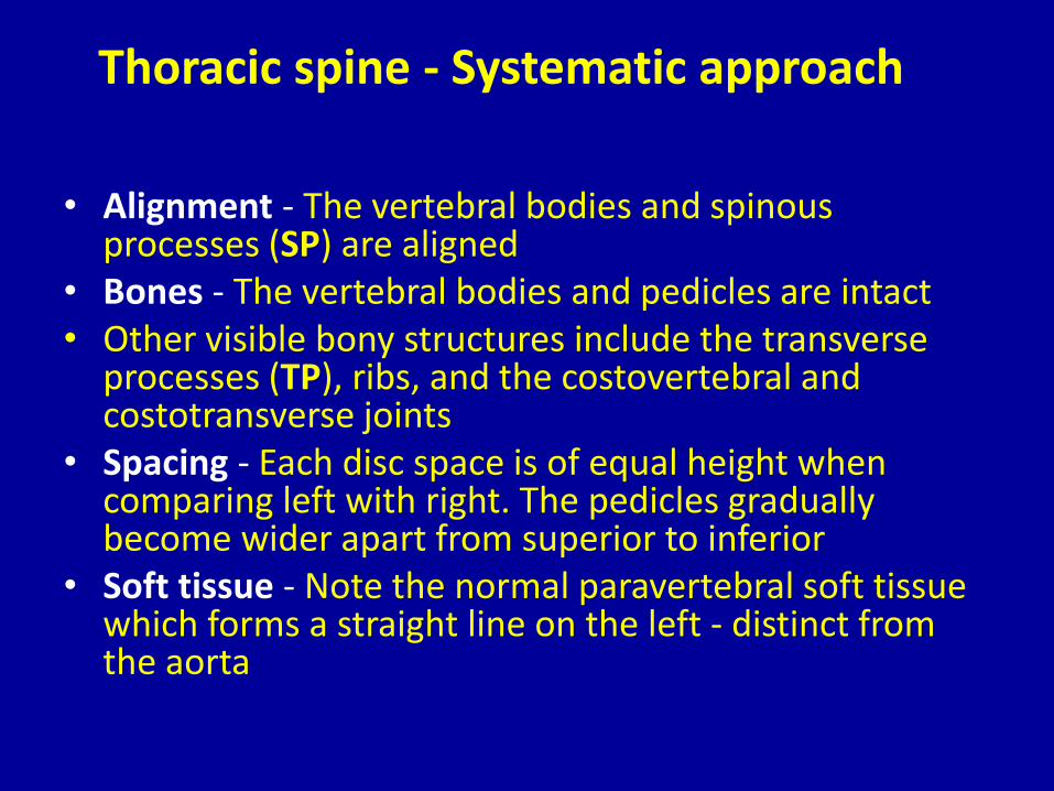
• Alignment - The vertebral bodies and spinous processes (SP) are aligned
• Bones - The vertebral bodies and pedicles are intact• Other visible bony structures include the transverse
processes (TP), ribs, and the costovertebral and costotransverse joints
• Spacing - Each disc space is of equal height when comparing left with right. The pedicles gradually become wider apart from superior to inferior
• Soft tissue - Note the normal paravertebral soft tissue which forms a straight line on the left - distinct from the aorta
Lumber Spine –Systemic Approach
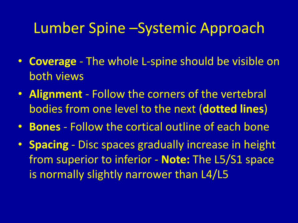
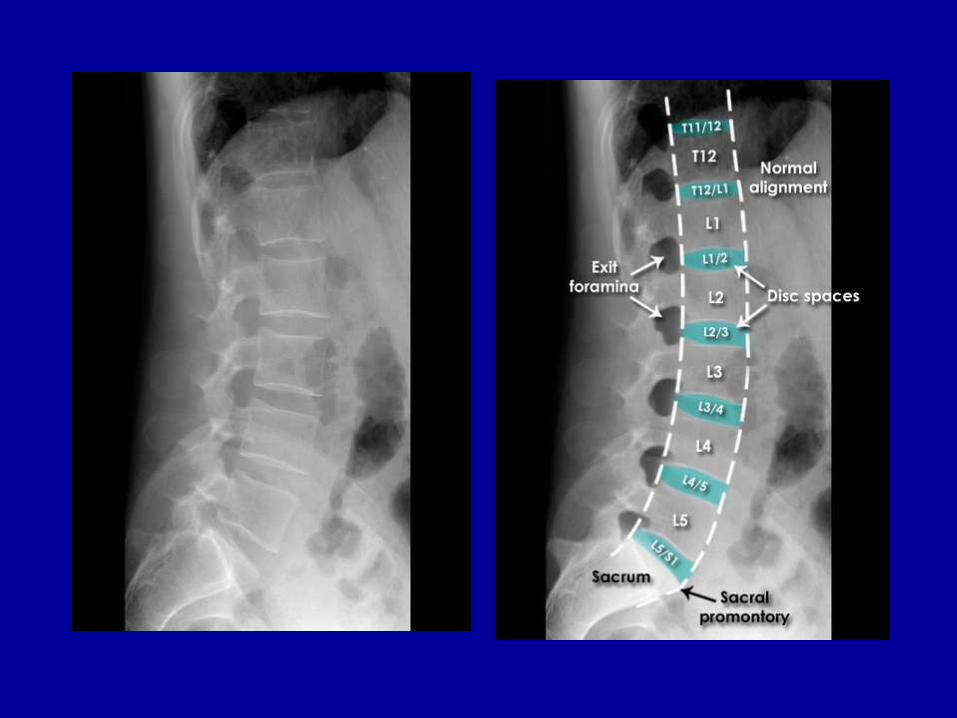
• Coverage - The whole L-spine should be visible on both views
• Alignment - Follow the corners of the vertebral bodies from one level to the next (dotted lines)
• Bones - Follow the cortical outline of each bone
• Spacing - Disc spaces gradually increase in height from superior to inferior - Note: The L5/S1 space is normally slightly narrower than L4/L5
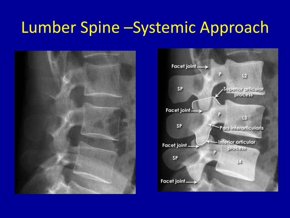
Lumber Spine –Systemic Approach
• Check the cortical outline of each vertebra
• The facet joints comprise the inferior and superior articular processes of each adjacent level
• The pars interarticularis literally means 'part between the joints'
• P = Pedicle
• SP = Spinous process
Lumber Spine –Systemic Approach
Lumber Spine –Systemic Approach
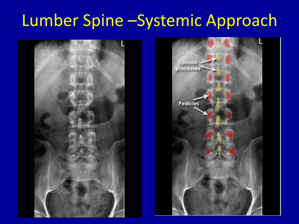
• Alignment - The vertebral bodies and spinous processes are aligned
• Bones - The vertebral bodies and pedicles are intact
• Spacing - Gradually increasing disc height from superior to inferior. The pedicles gradually become wider apart from superior to inferior -Note: The lower discs are angled away from the viewer and so are less easily assessed on this view
Lumber Spine –Systemic Approach
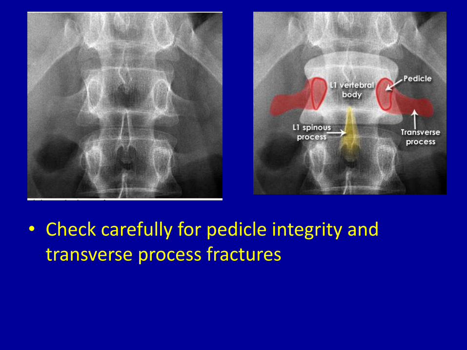
• Check carefully for pedicle integrity and transverse process fractures
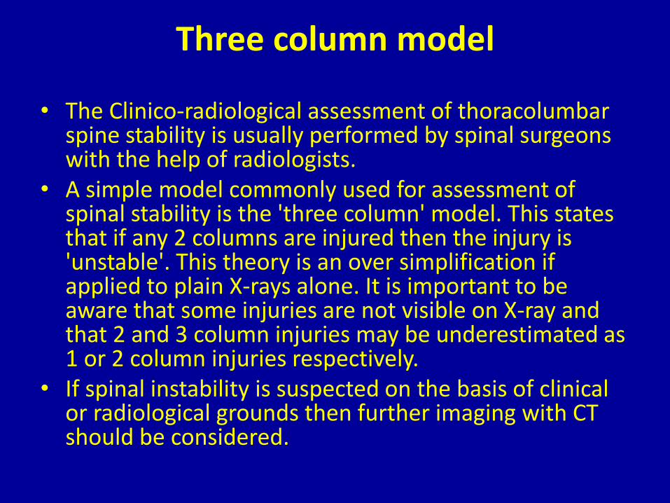
Three column model
• The Clinico-radiological assessment of thoracolumbar spine stability is usually performed by spinal surgeons with the help of radiologists.
• A simple model commonly used for assessment of spinal stability is the 'three column' model. This states that if any 2 columns are injured then the injury is 'unstable'. This theory is an over simplification if applied to plain X-rays alone. It is important to be aware that some injuries are not visible on X-ray and that 2 and 3 column injuries may be underestimated as 1 or 2 column injuries respectively.
• If spinal instability is suspected on the basis of clinical or radiological grounds then further imaging with CT should be considered.
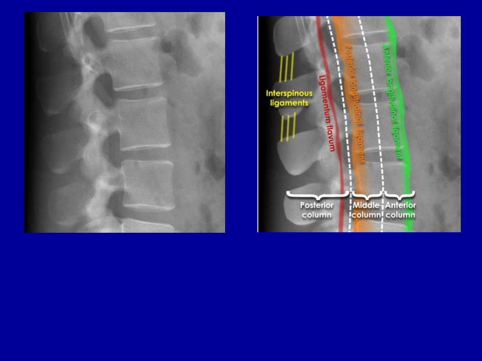
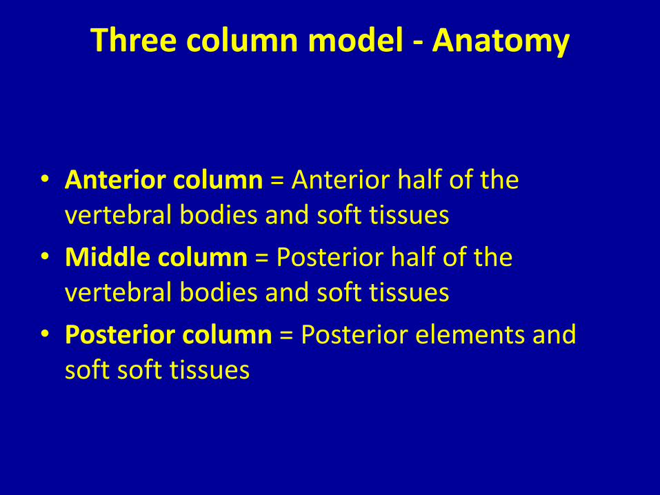
Three column model - Anatomy
• Anterior column = Anterior half of the vertebral bodies and soft tissues
• Middle column = Posterior half of the vertebral bodies and soft tissues
• Posterior column = Posterior elements and soft soft tissues
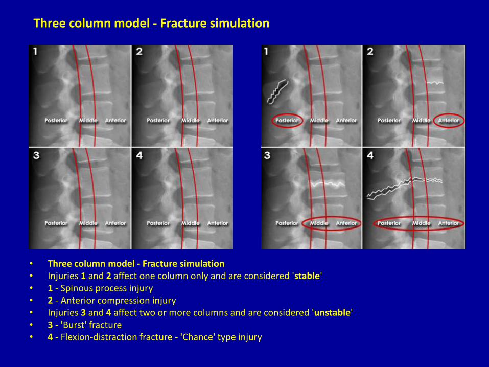
• Three column model - Fracture simulation • Injuries 1 and 2 affect one column only and are considered 'stable' • 1 - Spinous process injury • 2 - Anterior compression injury • Injuries 3 and 4 affect two or more columns and are considered 'unstable' • 3 - 'Burst' fracture • 4 - Flexion-distraction fracture - 'Chance' type injury
Three column model - Fracture simulation

THANX