Embed Size (px)
Citation preview
Master in Medical Physics ICTP 2015-2016
Absorbed dose in water for electron and photon beams
Francisco J.Hernández Flores∗
International Centre for Theoretical [email protected]
August 26, 2015
Abstract
During the practice of radiotherapy it was evaluated the rate of absorbed dose to waterin a water phantom at reference condition for photon beams and electrons beams in terms ofreferences used during the commissioning of the treatment unit following the procedures ofIAEA Code of Practice TRS 398, taking into account the follow condition size of field of10x10 cm2, the reference depth 5g/cm2 to electron beams and 10g/cm2 to photon beams,measures readings were corrected for influences quantities linked to factors such as: polarityeffect (kpol), electron recombination (ks), pressure and temperature (kTP) and electrometerfactor (kelec). using all this factor with the reading was calculated the absorb dose in waterDW,Q for diferent energy of photon beam and electrom beams; the absorbed dose in water forphoton of 6 MV was 34.33 cGy and for the photon of 15 MV was 38.63 cGy,; for electronbeam was calculated for three energy de results were 40.51 cGy for 6 MeV, 39.81cGy for 9MeV and 38.71 for 12 MeV of energy.
I. Introduction
It is recommended that quality assurance (QA) of the beam energy of radiotherapytreatment machines is carried out at regular intervals, either weekly or monthly. Thestandard for beam energy characterization is the measurement of depth ionizationcurves or depth dose curves in a water phantom using a suitable detector, and usually ameasurement such as dose at depth is taken as the metric. However, such measurementsare time-consuming and impractical on a regular basis in the clinical environment, andoften sampling of the beam at various depths in a solid phantom is used as the QAmeasurement to ensure that the beam energy is consistent with commissioning data. [3]
This practice only take into account one part of quality control of one treatmentunit, absorbed dose to water in a water phantom.
∗Radiotherapy Practical
1
Master in Medical Physics ICTP 2015-2016
II. Theory
I. Determination of the absorbed dose to water for photon
It is assumed that the user has an ionization chamber or a dosimeter with a calibrationfactor ND,w,Q0 in terms of absorbed dose to water at a reference quality Q0. The chamberis positioned according to the reference conditions and the absorbed dose to water isgiven by Equation 1 [1]
Dw,Q = MQND,w,Q0 kQ0 (1)
II. Correction for influence quantities
The calibration factor for an ionization chamber is valid only for the reference conditionswhich apply to the calibration. Any departure from the reference conditions when usingthe ionization chamber in the user beam should be corrected for using appropriatefactors.
II.1 Pressure, temperature and humidity
As all chambers recommended in this report are open to the ambient air, the mass ofair in the cavity volume is subject to atmospheric variations. The correction factor iscalculated by equation. 2
kTP =273.2 + T273.2 + T0
P0
P(2)
should be applied to convert the cavity air mass to the reference conditions. P andT are the cavity air pressure and temperature at the time of the measurements, and P0
and T0 are the reference values (generally 101.3 kPa and 20◦C).
II.2 Electrometer calibration
When the ionization chamber and the electrometer are calibrated separately, a calibra-tion factor for each is given by the calibration laboratory. In this Code of Practice, theelectrometer calibration factor kelec is treated as an influence quantity and is includedin the product ?ki of correction factors. Typically, the calibration factor ND,w for theionization chamber will be given in units of Gy/nC and that for the electrometer keleceither in units of nC/rdg.
II.3 Polarity effect
The effect on a chamber reading of using polarizing potentials of opposite polaritymust always be checked on commissioning. For most chamber types the effect will benegligible in photon beams, a notable exception being the very thin window chambersused for low energy X rays. In charged particle beams, particularly electrons,17 theeffect may be significant.
kpol =|M+|+ |M_|
2M(3)
2
Master in Medical Physics ICTP 2015-2016
where M+ and M_ are the electrometer readings obtained at positive and negativepolarity, respectively, and M is the electrometer reading obtained with the polarity usedroutinely
II.4 Ion recombination
The incomplete collection of charge in an ionization chamber cavity owing to therecombination of ions requires the use of a correction factor ks. Two separate effectstake place: (i) the recombination of ions formed by separate ionizing particle tracks,termed general (or volume) recombination, which is dependent on the density ofionizing particles and therefore on the dose rate; and (ii) the recombination of ionsformed by a single ionizing particle track, referred to as initial recombination, which isindependent of the dose rate. Both effects depend on the chamber geometry and on theapplied polarizing voltage. For beams other than heavy ions, initial recombination isgenerally less than 0.2%. The recombination correction factor ks at the normal operatingvoltage V1 is obtained from equation. 4 [1]
ks = a0 + a1
(M1
M2
)+ a2
(M1
M2
)(4)
III. Charge Measurement
The fully corrected charge reading from an ion chamber, M, is given by
M = MrawkskTPkeleckpol (5)
where Mraw is the raw ion chamber reading in coulombs, C, or the instrumentŠs readingunits (rdg).
IV. Determination of absorbed dose under reference conditions for electronBeam
The absorbed dose to water at the reference depth zref in water, in an electron beam ofquality Q and in the absence of the chamber, is given by equation 6.
Dw,Q = MQND,w,Q0 kQ,Q0 (6)
where MQ is the reading of the dosimeter corrected for the influence quantities tem-perature and pressure, electrometer calibration, polarity effect and ion recombination.The chamber should be positioned in accordance with the reference conditions. ND,w,Q0
is the calibration factor in terms of absorbed dose to water for the dosimeter at thereference quality Q0 and kQ,Q0 is a chamber specific factor which corrects for differencesbetween the reference beam quality Q0 and the actual beam quality Q. [1]
III. Material and method
Linear Accelerator Synergy of Elekta Oncology Systems, water phantom 3D withautomatic software connected to the console of the linear accelerator and computer that
3
Master in Medical Physics ICTP 2015-2016
have installed the program drive the movement of the ionization chamber during thescanner of data acquisition, electrometer PTW Unidos, barometer and thermometer, forphoton beam was used the ionization chamber type farmer and for electron beam wasused plane parallel chamber.
The head of the linear accelerator was adjusted to zero degree then proceeded toalign the phantom coincide reticle beam with the mark of the phantom, having properlyaligned the phantom ionization chamber was located following the instructions of thecode of practice of IAEA trs 398 for both photons and electrons beam.
For evaluate the absorbed dose in water for Photon beam were realized Threemeasurements for each photon energy 6 MV and 15 MV were performed, standardenvironmental conditions temperature and pressure was measured to evaluate the kTP
factor, three measurements with different polarity for evaluated the Polarity effect Kpol ,three reading with different polarity value for the ions recombination factor ks.
For evaluate the absorbed dose in water phantom for electron beam in accelera-tor Synergy Agility were ionization chamber parallel plane, electrometer barometerthermometer, phantom of water 3D and software Mephisto. we install the wholesystem then aligns the phantom and finally the camera then proceeded to measure theabsorbed dose for the reference field at the reference depth for various energies of theelectron beam.
IV. Discussion and analysis of Results
I. First Practice Determination absorbed dose in water for Photon Beam.
The table 1 contains the reading measure for photon beams 6 MV and 15 MV delivery50 MU in the console of linear accelerator with the camera positioning at 10 cm depthand central axis of the beams.
N◦ Reading Reading [nC] Energy of beam [MV]1 6.389 62 6.377 63 6.377 6
Average 6.3811 7.280 152 7.279 153 7.281 15
Average 7.280
Table 1: Lecture Measure in referennce condition
The table 2 and table 3 show the data calculated for different Correction factor thatinfluence quantities in the reading. all these factor were measured using worksheetfrom excel, the beam quality was obtained through interpolation.
4
Master in Medical Physics ICTP 2015-2016
Energy [MV] kQ kpol ks ND,w[cGy/nC]6 0.99 1.0005 1.0021 5.364
SSD [cm] Field [cm2] Zre f [cm] TPR20/10 kTP
100 10x10 10 0.6837 1.015
Table 2: Data from photon of 6 MV of energy
Energy [MV] kQ kpol ks ND,w[cGy/nC]15 0.974 1.0003 1.0048 5.364
SSD [cm] Field [cm2] Zre f [cm] TPR20/10 kTP
100 10x10 10 0.6837 1.015
Table 3: Data from photon of 15 MV of energy
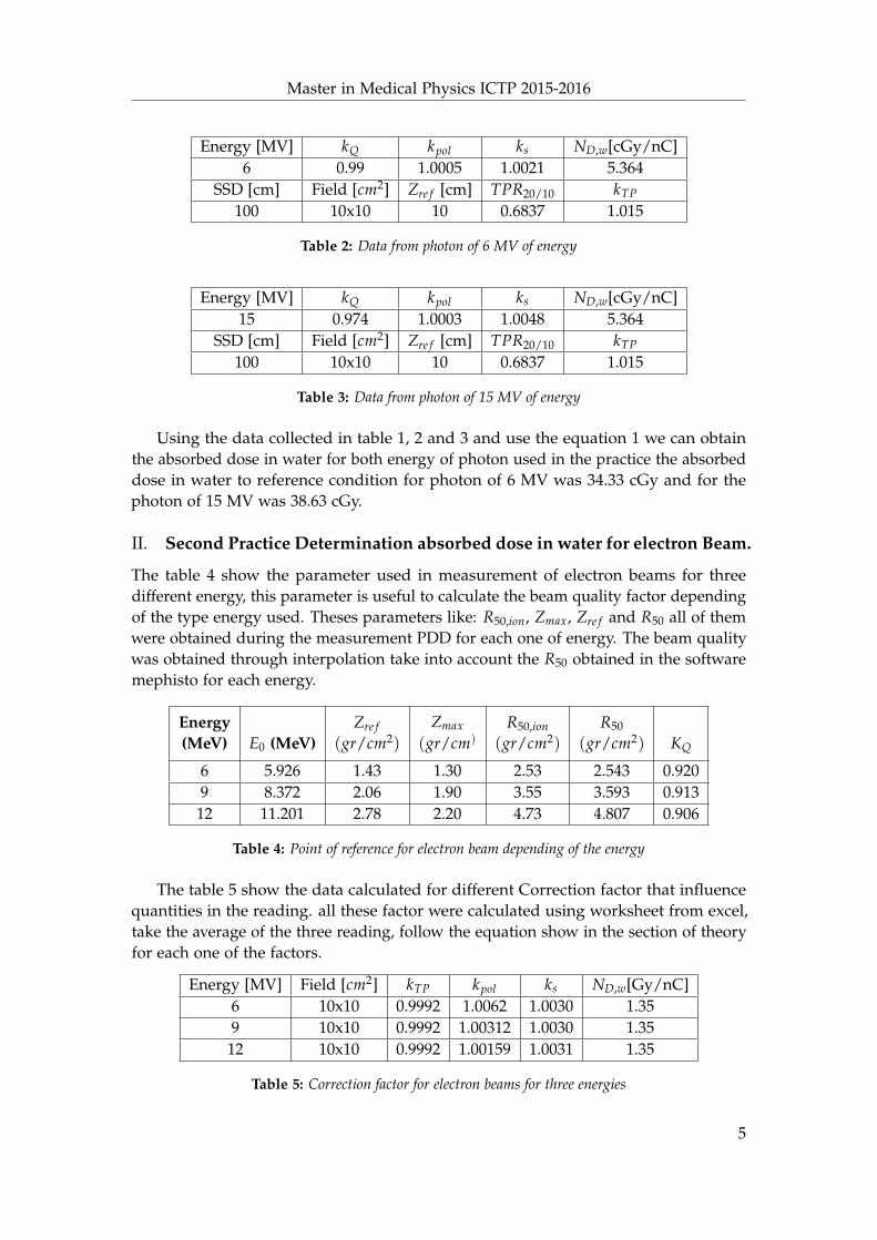
Using the data collected in table 1, 2 and 3 and use the equation 1 we can obtainthe absorbed dose in water for both energy of photon used in the practice the absorbeddose in water to reference condition for photon of 6 MV was 34.33 cGy and for thephoton of 15 MV was 38.63 cGy.
II. Second Practice Determination absorbed dose in water for electron Beam.
The table 4 show the parameter used in measurement of electron beams for threedifferent energy, this parameter is useful to calculate the beam quality factor dependingof the type energy used. Theses parameters like: R50,ion, Zmax, Zre f and R50 all of themwere obtained during the measurement PDD for each one of energy. The beam qualitywas obtained through interpolation take into account the R50 obtained in the softwaremephisto for each energy.
Energy(MeV) E0 (MeV)
Zre f(gr/cm2)
Zmax
(gr/cm)R50,ion
(gr/cm2)
R50
(gr/cm2) KQ
6 5.926 1.43 1.30 2.53 2.543 0.9209 8.372 2.06 1.90 3.55 3.593 0.91312 11.201 2.78 2.20 4.73 4.807 0.906
Table 4: Point of reference for electron beam depending of the energy
The table 5 show the data calculated for different Correction factor that influencequantities in the reading. all these factor were calculated using worksheet from excel,take the average of the three reading, follow the equation show in the section of theoryfor each one of the factors.
Energy [MV] Field [cm2] kTP kpol ks ND,w[Gy/nC]6 10x10 0.9992 1.0062 1.0030 1.359 10x10 0.9992 1.00312 1.0030 1.3512 10x10 0.9992 1.00159 1.0031 1.35
Table 5: Correction factor for electron beams for three energies
5
Master in Medical Physics ICTP 2015-2016
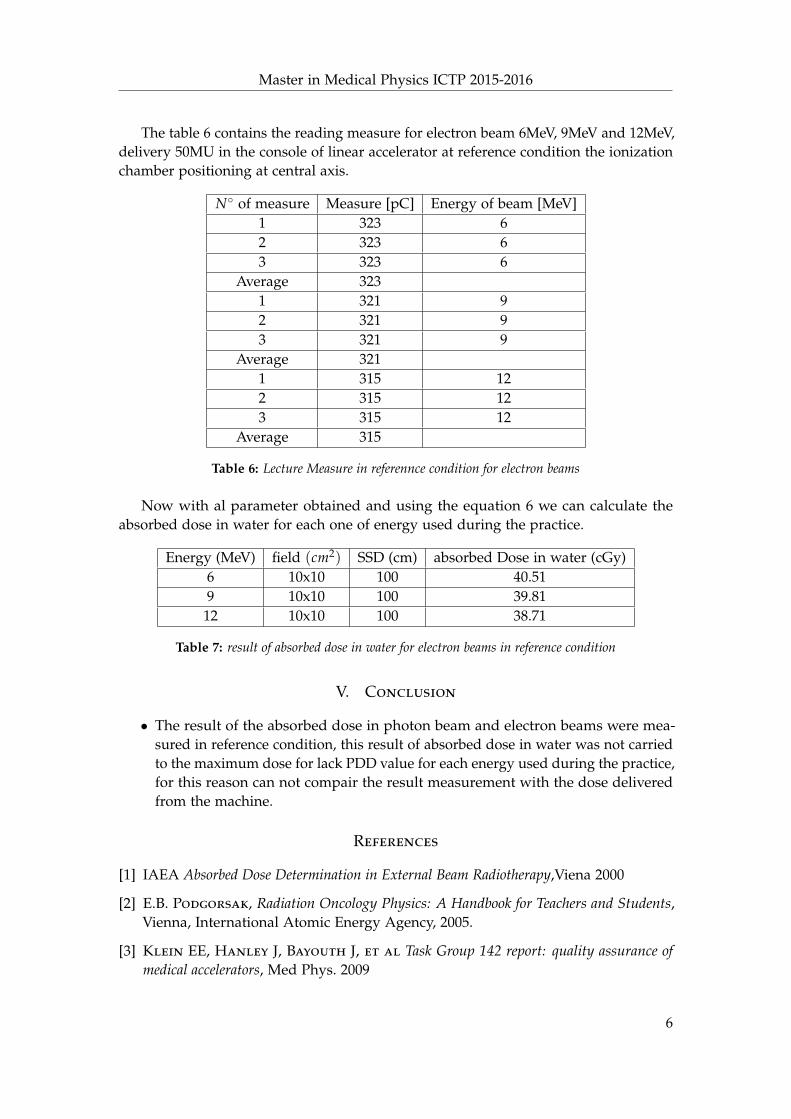
The table 6 contains the reading measure for electron beam 6MeV, 9MeV and 12MeV,delivery 50MU in the console of linear accelerator at reference condition the ionizationchamber positioning at central axis.
N◦ of measure Measure [pC] Energy of beam [MeV]1 323 62 323 63 323 6
Average 3231 321 92 321 93 321 9
Average 3211 315 122 315 123 315 12
Average 315
Table 6: Lecture Measure in referennce condition for electron beams
Now with al parameter obtained and using the equation 6 we can calculate theabsorbed dose in water for each one of energy used during the practice.
Energy (MeV) field (cm2) SSD (cm) absorbed Dose in water (cGy)6 10x10 100 40.519 10x10 100 39.8112 10x10 100 38.71
Table 7: result of absorbed dose in water for electron beams in reference condition
V. Conclusion
• The result of the absorbed dose in photon beam and electron beams were mea-sured in reference condition, this result of absorbed dose in water was not carriedto the maximum dose for lack PDD value for each energy used during the practice,for this reason can not compair the result measurement with the dose deliveredfrom the machine.
References
[1] IAEA Absorbed Dose Determination in External Beam Radiotherapy,Viena 2000
[2] E.B. Podgorsak, Radiation Oncology Physics: A Handbook for Teachers and Students,Vienna, International Atomic Energy Agency, 2005.
[3] Klein EE, Hanley J, Bayouth J, et al Task Group 142 report: quality assurance ofmedical accelerators, Med Phys. 2009
6


![Major accidents in radiotherapy - Indico [Home]indico.ictp.it/event/a13209/session/5/contribution/6/... · 2014. 11. 27. · Major accidents in radiotherapy … related to treatment](https://img.pdfslide.us/doc/110x75/60e167cb7648eb530e2a9365/major-accidents-in-radiotherapy-indico-home-2014-11-27-major-accidents.jpg)