Embed Size (px)
Citation preview
Facilitators: -
Dr. B. M. Gurupadayya,
Dr. R. S. Chandan,
Dept. of pharmaceutical chemistry,
JSS college of pharmacy,
Mysuru.
Submitted by: -Ram Mohan S.R.
1st M.Pharm
Pharmaceutical Quality AssuranceJSS college of pharmacy
Mysuru
Pharmaceutical Quality Assurance, Department of Pharmaceutics.1
INTRODUCTION
• The injection system is positioned after the pump head.
• The injection of a sample at atmospheric pressure into the system, at high pressure, represents a critical step in the chromatographic process.
• Sample injection valves, or switching valves, are used to introduce reproducible amounts of sample into the HPLC eluent stream without causing changes in pressure or flow.
Pharmaceutical Quality Assurance, Department of Pharmaceutics.2
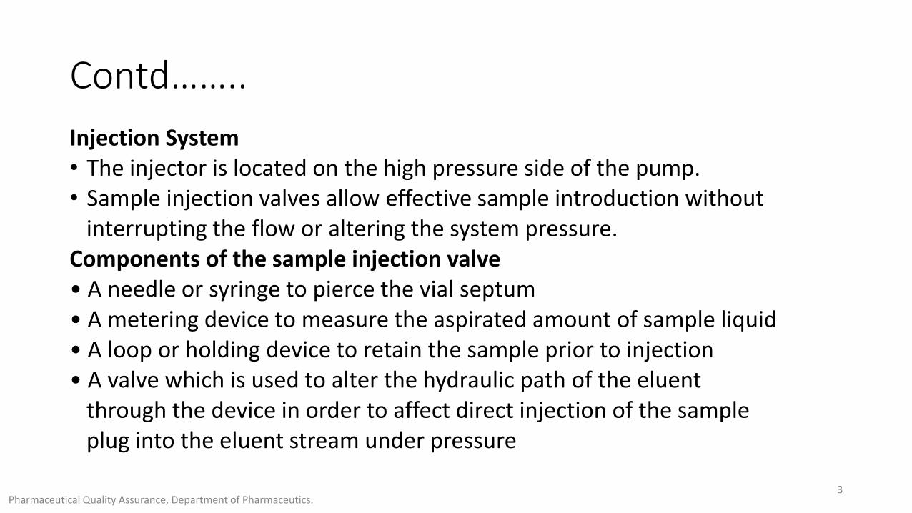
Contd……..
Injection System• The injector is located on the high pressure side of the pump.• Sample injection valves allow effective sample introduction without
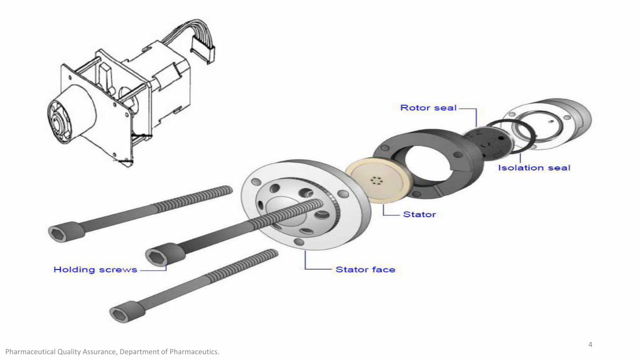
interrupting the flow or altering the system pressure.Components of the sample injection valve• A needle or syringe to pierce the vial septum• A metering device to measure the aspirated amount of sample liquid• A loop or holding device to retain the sample prior to injection• A valve which is used to alter the hydraulic path of the eluent
through the device in order to affect direct injection of the sampleplug into the eluent stream under pressure
Pharmaceutical Quality Assurance, Department of Pharmaceutics.3
Pharmaceutical Quality Assurance, Department of Pharmaceutics.4
Pharmaceutical Quality Assurance, Department of Pharmaceutics.5
Manual Injection Systems
• Manual sample injectors for HPLC transfer sample at atmospheric pressure from a syringe to a Sample Loop. The loop is then connected via a change in valve configuration, to the high-pressure mobile phase stream, which carries the sample onto the column.
There are two methods of loading the sample:
• Complete-filling –where the loop size chosen has the desired injection volume and is totally filled with sample
• Partial-filling –where the loop chosen is at least twice the required sample volume and is only partially filled
Pharmaceutical Quality Assurance, Department of Pharmaceutics.6
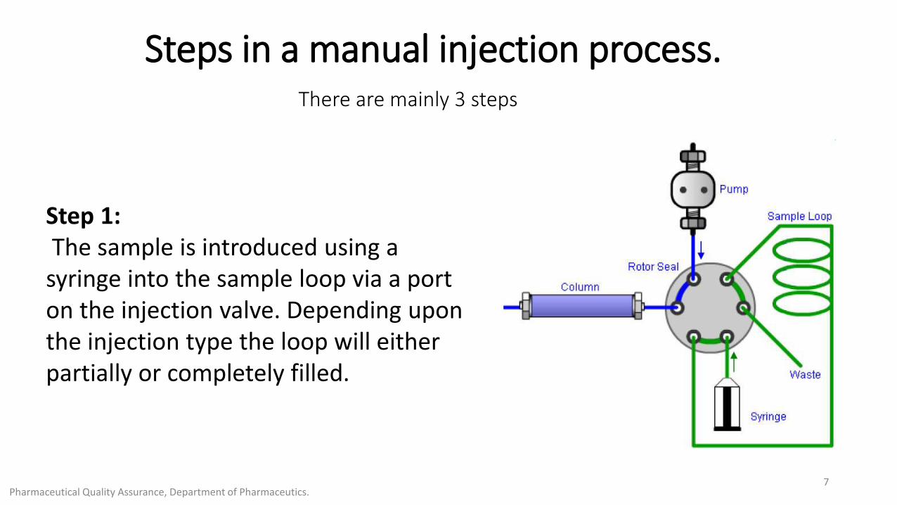
Steps in a manual injection process.There are mainly 3 steps
Step 1:The sample is introduced using a
syringe into the sample loop via a port on the injection valve. Depending upon the injection type the loop will either partially or completely filled.
Pharmaceutical Quality Assurance, Department of Pharmaceutics.7
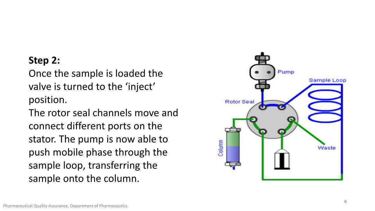
Step 2: Once the sample is loaded the valve is turned to the ‘inject’ position.The rotor seal channels move and connect different ports on the stator. The pump is now able to push mobile phase through the sample loop, transferring the sample onto the column.
Pharmaceutical Quality Assurance, Department of Pharmaceutics.8
Step 3:
Once the injection has been made the valve is returned to the ‘load’ position.
This enables loop filling for the next injection.
Some people prefer to leave in the inject position until the next injection is required to completely flush the loop and reduce ‘carryover’
Pharmaceutical Quality Assurance, Department of Pharmaceutics.9
Pharmaceutical Quality Assurance, Department of Pharmaceutics.10
VIDEO-1
Autosamplers
All autosamplers have the same basic components which include,
• The injection valve,
• A syringe or sampling needle,
• A loop of either fixed or adjustable volume,
• A metering pump to aspirate the sample from the vial and an injection port through which the sample is introduced into the loop.
Most autosamplers use six-port loop injection valves in order to deliver the sample plug to the analytical column.
Pharmaceutical Quality Assurance, Department of Pharmaceutics.11
There are three main operating principles which are used in autosampler design:
1. Pull-to-fill
2. Push-to-fill
3. Integral-loop autosamplers
Pharmaceutical Quality Assurance, Department of Pharmaceutics.12
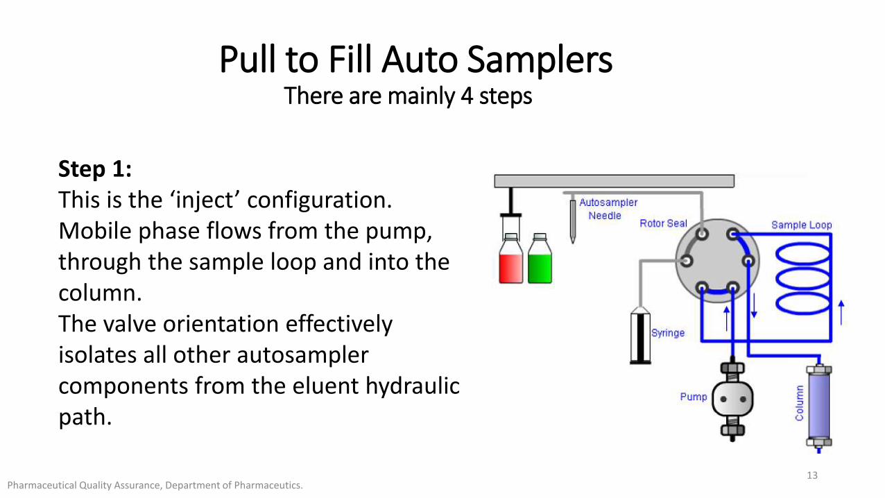
Pull to Fill Auto SamplersThere are mainly 4 steps
Step 1:This is the ‘inject’ configuration. Mobile phase flows from the pump, through the sample loop and into the column. The valve orientation effectivelyisolates all other autosampler components from the eluent hydraulic path.
Pharmaceutical Quality Assurance, Department of Pharmaceutics.13
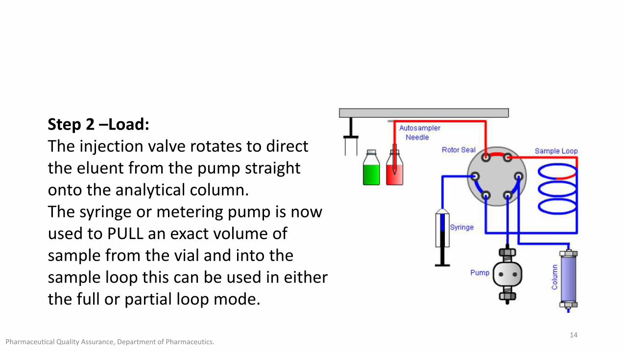
Step 2 –Load: The injection valve rotates to direct the eluent from the pump straight onto the analytical column.The syringe or metering pump is now used to PULL an exact volume of sample from the vial and into the sample loop this can be used in either the full or partial loop mode.
Pharmaceutical Quality Assurance, Department of Pharmaceutics.14
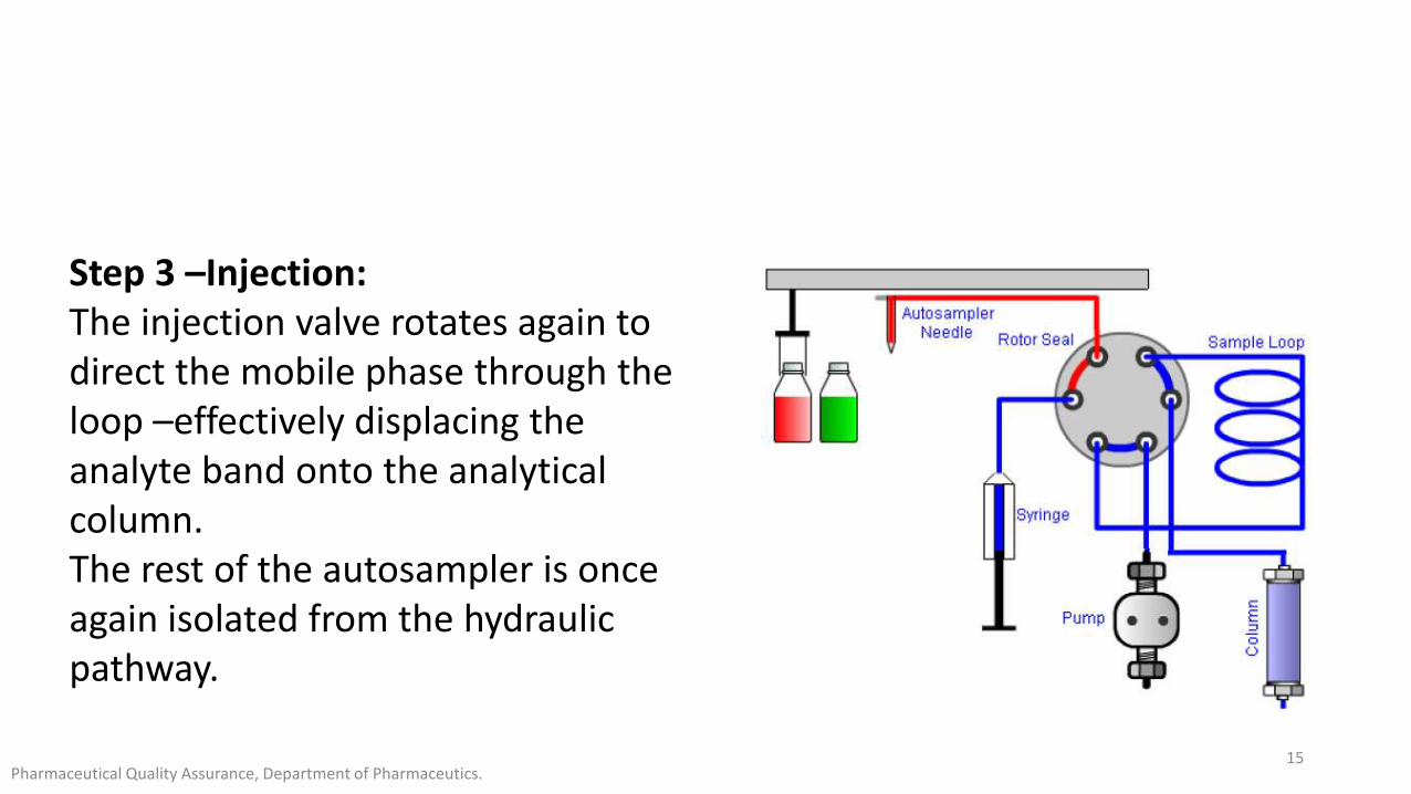
Step 3 –Injection: The injection valve rotates again to direct the mobile phase through the loop –effectively displacing the analyte band onto the analyticalcolumn. The rest of the autosampler is once again isolated from the hydraulic pathway.
Pharmaceutical Quality Assurance, Department of Pharmaceutics.15
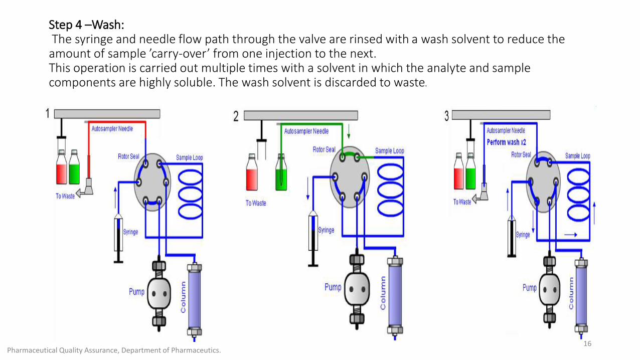
Step 4 –Wash:The syringe and needle flow path through the valve are rinsed with a wash solvent to reduce the amount of sample ’carry-over’ from one injection to the next.This operation is carried out multiple times with a solvent in which the analyte and samplecomponents are highly soluble. The wash solvent is discarded to waste.
Pharmaceutical Quality Assurance, Department of Pharmaceutics.16
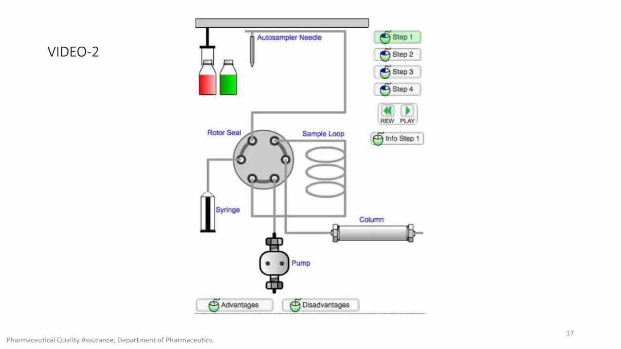
VIDEO-2
Pharmaceutical Quality Assurance, Department of Pharmaceutics.17
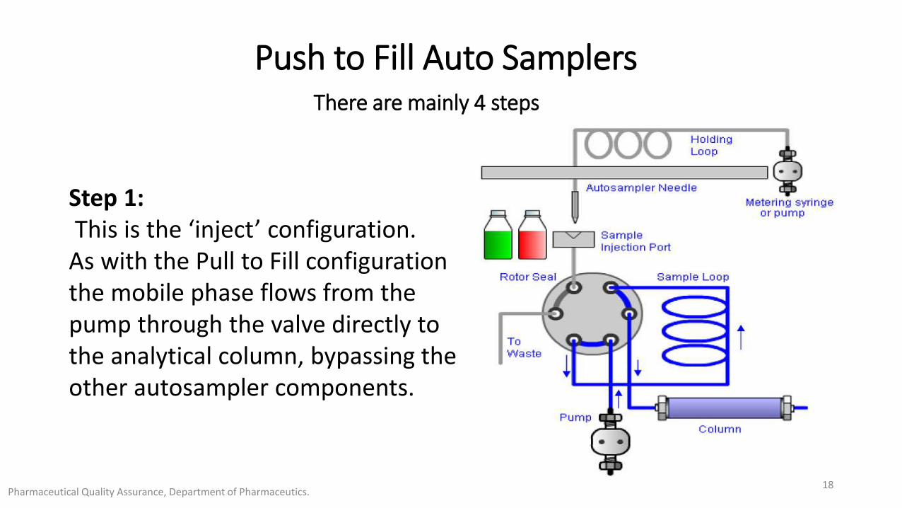
Push to Fill Auto SamplersThere are mainly 4 steps
Step 1:This is the ‘inject’ configuration.
As with the Pull to Fill configuration the mobile phase flows from the pump through the valve directly to the analytical column, bypassing the other autosampler components.
Pharmaceutical Quality Assurance, Department of Pharmaceutics.18
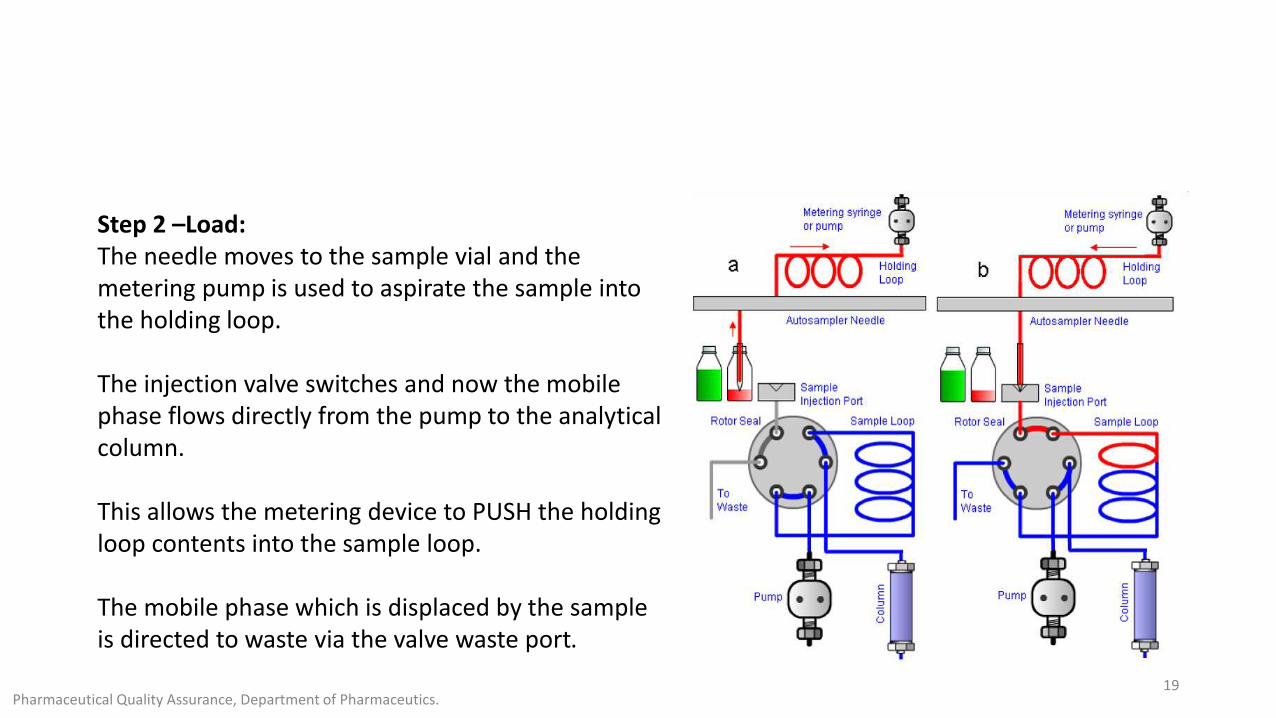
Step 2 –Load: The needle moves to the sample vial and the metering pump is used to aspirate the sample into the holding loop.
The injection valve switches and now the mobile phase flows directly from the pump to the analytical column.
This allows the metering device to PUSH the holding loop contents into the sample loop.
The mobile phase which is displaced by the sample is directed to waste via the valve waste port.
Pharmaceutical Quality Assurance, Department of Pharmaceutics.19
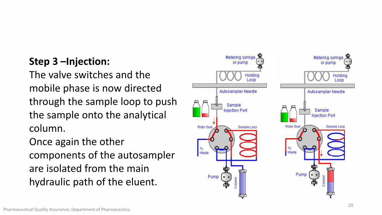
Step 3 –Injection: The valve switches and the mobile phase is now directed through the sample loop to push the sample onto the analytical column. Once again the othercomponents of the autosampler are isolated from the main hydraulic path of the eluent.
Pharmaceutical Quality Assurance, Department of Pharmaceutics.20

Step 4 –Wash: A wash solvent may be used at this point to flush any remainingsample components out of the system. The analyte and other sample components should be highly soluble in the wash solvent.
Pharmaceutical Quality Assurance, Department of Pharmaceutics.21
Integral Loop Auto Samplers
• In recent years, the integral loop autosampler has become popular. The strong point of this design is that no sample is wasted and this can be very important for trace analysis when sample volume is limited.
• Because the sample is contained completely within the swept portion of the loop, the entire volume of loaded sample is injected. Additionally, continual flushing of the injection switching valve and loop following injection helps eliminate sample carryover effects.
Pharmaceutical Quality Assurance, Department of Pharmaceutics.22
There are mainly 4 steps
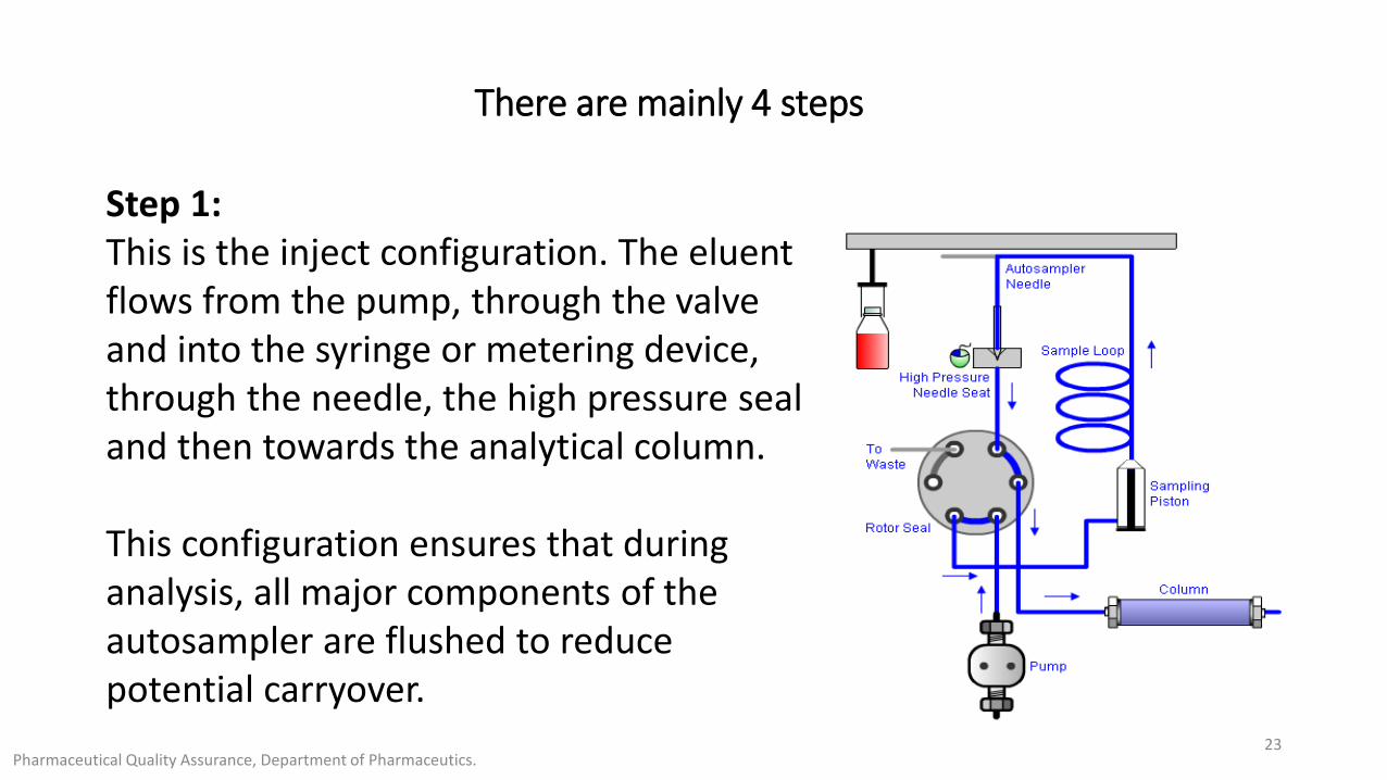
Step 1: This is the inject configuration. The eluent flows from the pump, through the valve and into the syringe or metering device, through the needle, the high pressure seal and then towards the analytical column.
This configuration ensures that during analysis, all major components of the autosampler are flushed to reduce potential carryover.
Pharmaceutical Quality Assurance, Department of Pharmaceutics.23
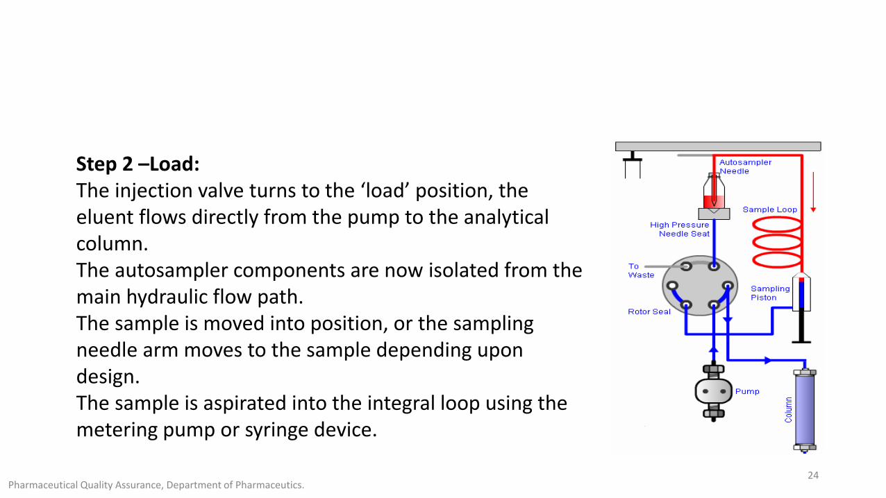
Step 2 –Load: The injection valve turns to the ‘load’ position, the eluent flows directly from the pump to the analytical column.The autosampler components are now isolated from the main hydraulic flow path. The sample is moved into position, or the sampling needle arm moves to the sample depending upon design.The sample is aspirated into the integral loop using the metering pump or syringe device.
Pharmaceutical Quality Assurance, Department of Pharmaceutics.24
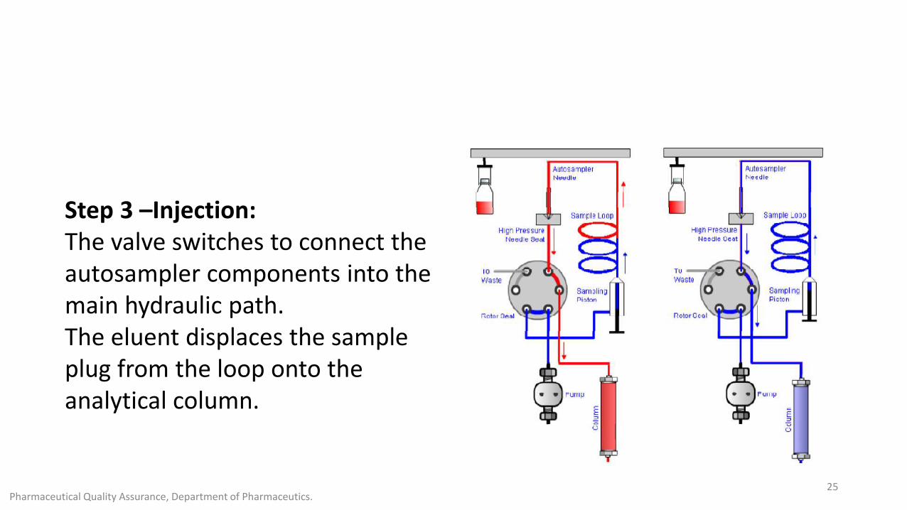
Step 3 –Injection: The valve switches to connect the autosampler components into themain hydraulic path. The eluent displaces the sample plug from the loop onto theanalytical column.
Pharmaceutical Quality Assurance, Department of Pharmaceutics.25
Step 4 –Wash:
A wash solvent may be used at this point to flush any remaining sample components out of the system.
The analyte and other sample components should be highly soluble in the wash solvent.
Pharmaceutical Quality Assurance, Department of Pharmaceutics.26

Pharmaceutical Quality Assurance, Department of Pharmaceutics.27
VIDEO-3

Pharmaceutical Quality Assurance, Department of Pharmaceutics.28
REFERENCES
WWW.CHROMacademy.com
VIDEO-1 Chem4all-media Library
VIDEO-2 CHROMacamady
VIDEO-3 Agilent Life Channel
Pharmaceutical Quality Assurance, Department of Pharmaceutics.29
Pharmaceutical Quality Assurance, Department of Pharmaceutics.30