Embed Size (px)
Citation preview
1 | P a g e
LECTURE 1
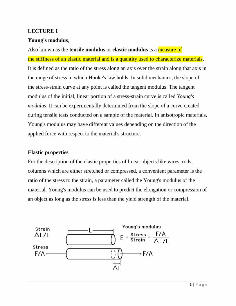
Young's modulus,
Also known as the tensile modulus or elastic modulus is a measure of
the stiffness of an elastic material and is a quantity used to characterize materials.
It is defined as the ratio of the stress along an axis over the strain along that axis in
the range of stress in which Hooke's law holds. In solid mechanics, the slope of
the stress-strain curve at any point is called the tangent modulus. The tangent
modulus of the initial, linear portion of a stress-strain curve is called Young's
modulus. It can be experimentally determined from the slope of a curve created
during tensile tests conducted on a sample of the material. In anisotropic materials,
Young's modulus may have different values depending on the direction of the
applied force with respect to the material's structure.
Elastic properties
For the description of the elastic properties of linear objects like wires, rods,
columns which are either stretched or compressed, a convenient parameter is the
ratio of the stress to the strain, a parameter called the Young's modulus of the
material. Young's modulus can be used to predict the elongation or compression of
an object as long as the stress is less than the yield strength of the material.
2 | P a g e
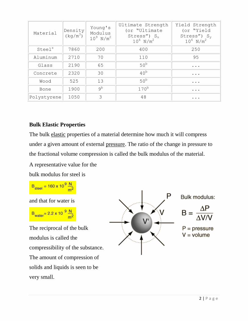
Bulk Elastic Properties
The bulk elastic properties of a material determine how much it will compress
under a given amount of external pressure. The ratio of the change in pressure to
the fractional volume compression is called the bulk modulus of the material.
A representative value for the
bulk modulus for steel is
and that for water is
The reciprocal of the bulk
modulus is called the
compressibility of the substance.
The amount of compression of
solids and liquids is seen to be
very small.
Material Density
(kg/m3)
Young's
Modulus
109 N/m
2
Ultimate Strength
(or “Ultimate
Stress”) Su
106 N/m
2
Yield Strength
(or “Yield
Stress”) Sy
106 N/m
2
Steels 7860 200 400 250
Aluminum 2710 70 110 95
Glass 2190 65 50b ...
Concrete 2320 30 40b ...
Wood 525 13 50b ...
Bone 1900 9b 170
b ...
Polystyrene 1050 3 48 ...
3 | P a g e
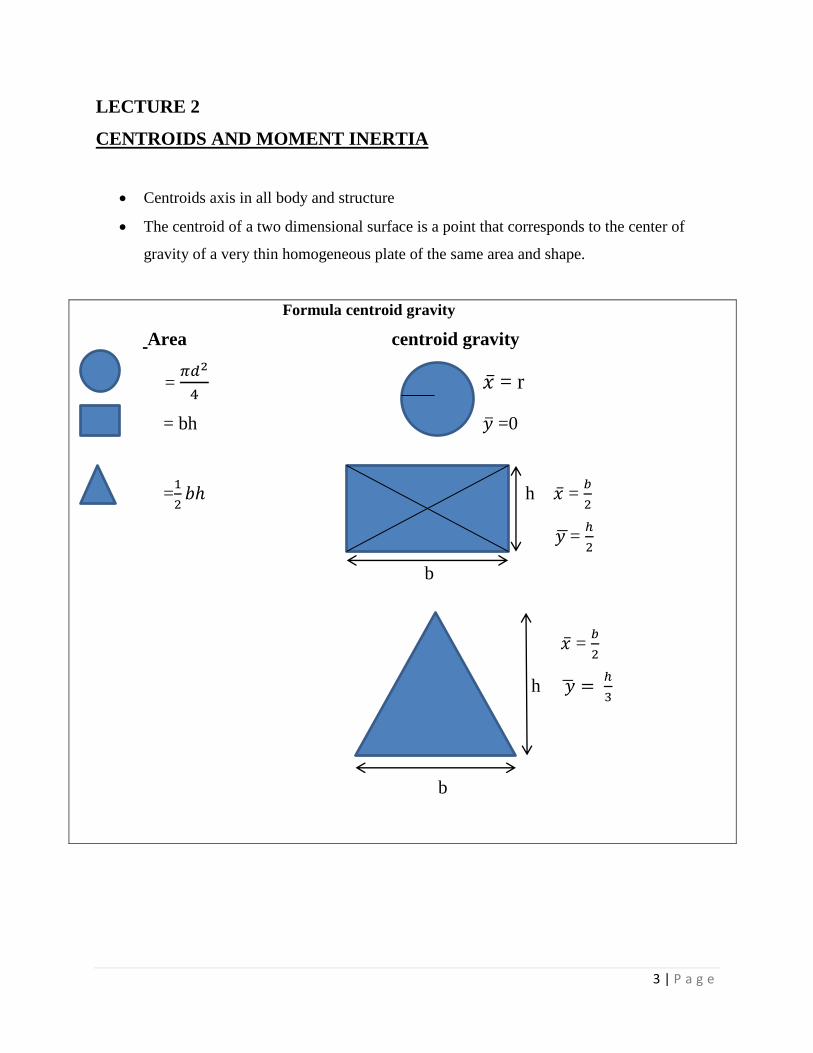
LECTURE 2
CENTROIDS AND MOMENT INERTIA
Centroids axis in all body and structure
The centroid of a two dimensional surface is a point that corresponds to the center of
gravity of a very thin homogeneous plate of the same area and shape.
Formula centroid gravity
Area centroid gravity
=
0 = r
= bh =0
=
h =
=
b
=
h
b
4 | P a g e
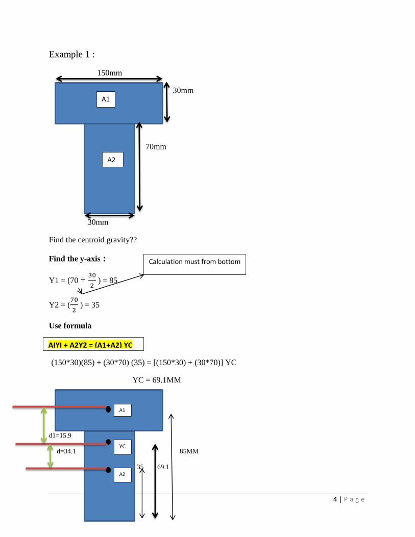
Example 1 :
150mm
30mm
70mm
30mm
Find the centroid gravity??
Find the y-axis :
Y1 = (70 +
) = 85
Y2 = (
) = 35
Use formula
(150*30)(85) + (30*70) (35) = [(150*30) + (30*70)] YC
YC = 69.1MM
d1=15.9
d=34.1 85MM
35 69.1
A1
A2
Calculation must from bottom
AIYI + A2Y2 = (A1+A2) YC
A2
A1
YC
5 | P a g e
MOMENT INERTIA (I)
Also known as the Second Moment of the Area is a term used to describe the capacity of a
cross-section to resist bending.
It is a mathematical property of a section concerned with a surface area and how that area
is distributed about the reference axis. The reference axis is usually a centroid axis
It is used to determine the state of stress in a section.
It is used to calculate the resistance to bending.
It can be used to determine the amount of deflection in a beam.
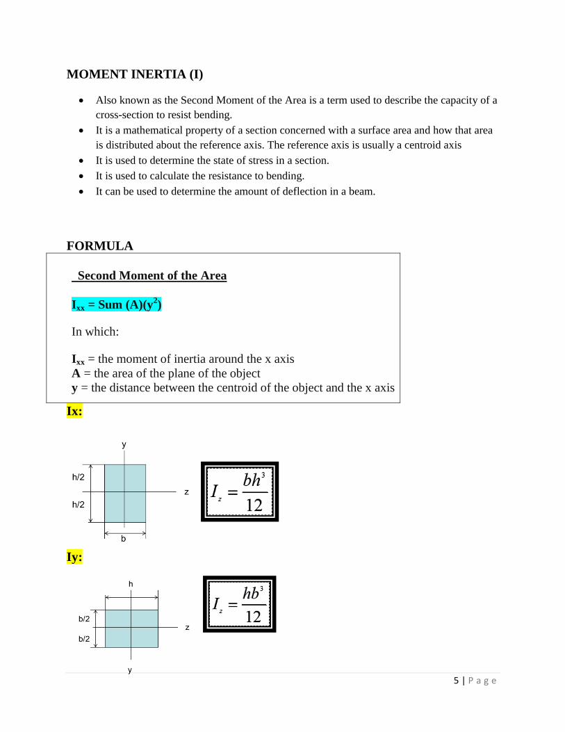
FORMULA
Second Moment of the Area
Ixx = Sum (A)(y2)
In which:
Ixx = the moment of inertia around the x axis
A = the area of the plane of the object
y = the distance between the centroid of the object and the x axis
Ix:
Iy:
6 | P a g e
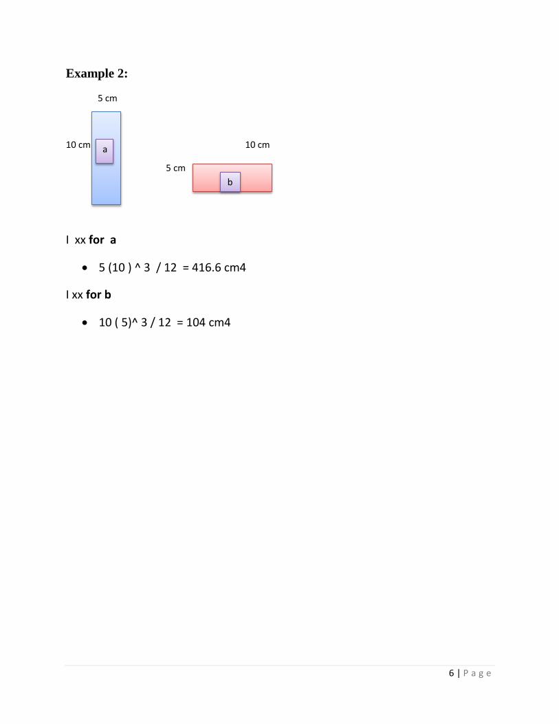
Example 2:
5 cm
10 cm 10 cm
5 cm
I xx for a
5 (10 ) ^ 3 / 12 = 416.6 cm4
I xx for b
10 ( 5)^ 3 / 12 = 104 cm4
a
b
7 | P a g e
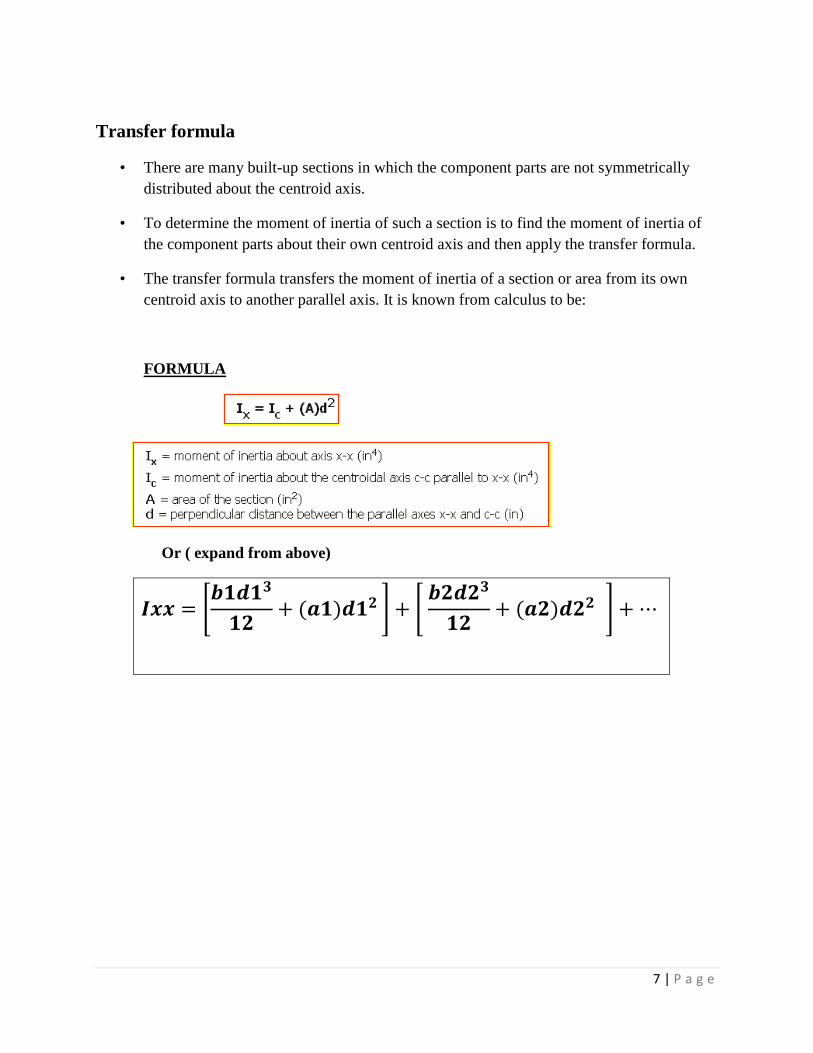
Transfer formula
• There are many built-up sections in which the component parts are not symmetrically
distributed about the centroid axis.
• To determine the moment of inertia of such a section is to find the moment of inertia of
the component parts about their own centroid axis and then apply the transfer formula.
• The transfer formula transfers the moment of inertia of a section or area from its own
centroid axis to another parallel axis. It is known from calculus to be:
FORMULA
Or ( expand from above)
[
] [
]
8 | P a g e
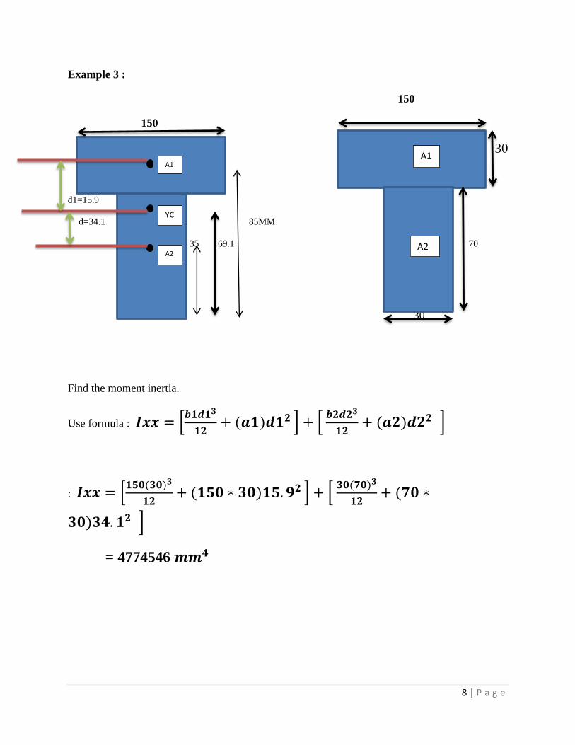
Example 3 :
150
150
30
d1=15.9
d=34.1 85MM
35 69.1 70
30
Find the moment inertia.
Use formula : [
] [
]
: [
] [
]
= 4774546
A2
A1
YC
A1
A2

9 | P a g e
LECTURE 3
BENDING STRES
Formula
Unit: N/mm^2
WHERE: Z= I/Y Y= center gravity to participate section M= bending moment
F=
=
10 | P a g e
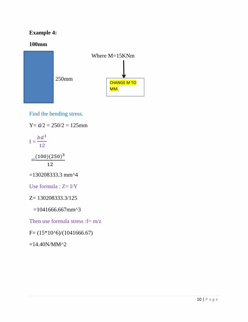
Example 4:
100mm
Where M=15KNm
250mm
Find the bending stress.
Y= d/2 = 250/2 = 125mm
I =
=
=130208333.3 mm^4
Use formula : Z= I/Y
Z= 130208333.3/125
=1041666.667mm^3
Then use formula stress :f= m/z
F= (15*10^6)/(1041666.67)
=14.40N/MM^2
CHANGE M TO
MM.

11 | P a g e
BENDING FORMULA in Combined Stress
Z is termed as Modulus of section = I/y
I – moment inertia; y – distance from Neutral axis to stress level
M – Applied moment (from loads)
Combined Stress – bending and compression
12 | P a g e
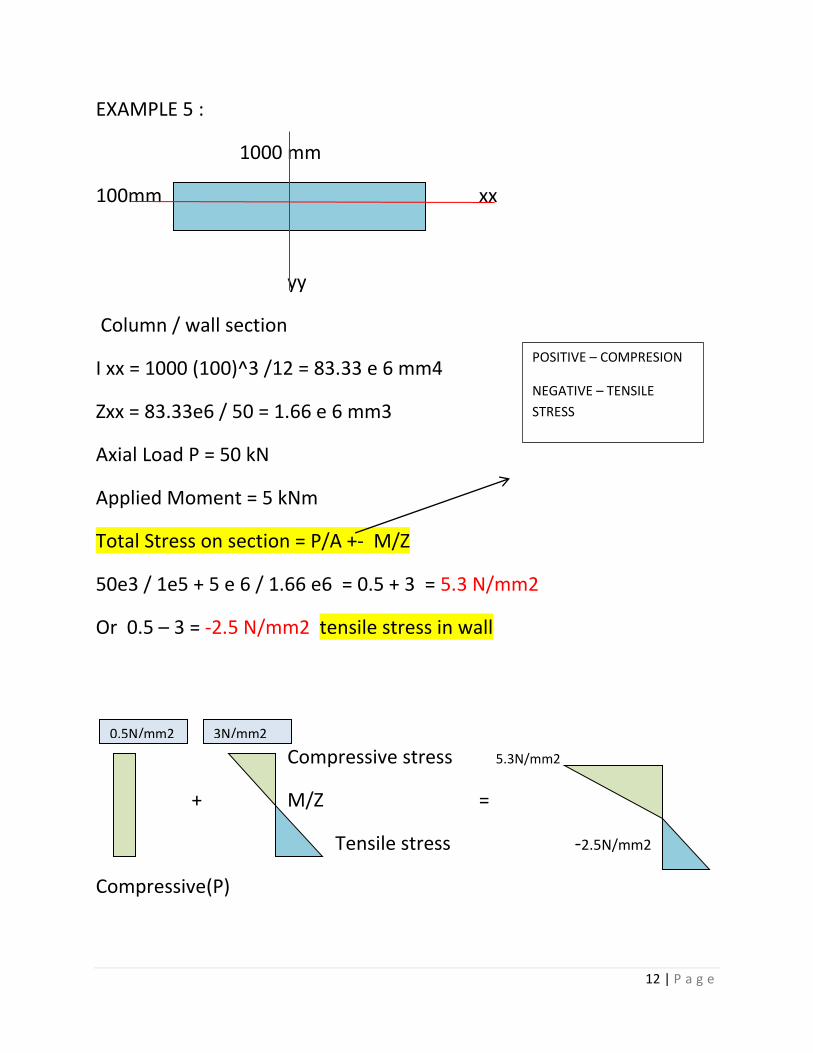
EXAMPLE 5 :
1000 mm
100mm xx
yy
Column / wall section
I xx = 1000 (100)^3 /12 = 83.33 e 6 mm4
Zxx = 83.33e6 / 50 = 1.66 e 6 mm3
Axial Load P = 50 kN
Applied Moment = 5 kNm
Total Stress on section = P/A +- M/Z
50e3 / 1e5 + 5 e 6 / 1.66 e6 = 0.5 + 3 = 5.3 N/mm2
Or 0.5 – 3 = -2.5 N/mm2 tensile stress in wall
Compressive stress 5.3N/mm2
+ M/Z =
Tensile stress -2.5N/mm2
Compressive(P)
0.5N/mm2 3N/mm2
POSITIVE – COMPRESION
NEGATIVE – TENSILE
STRESS

13 | P a g e
SHEAR STRESSES
The formula for shear stress in beams is a as below
Where :
V - shear force at that section
Q – first moment of area
I – moment of inertia
b- breadth of web
14 | P a g e
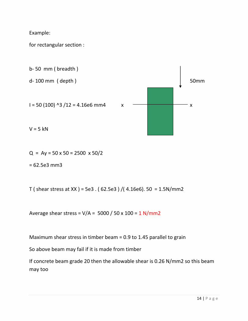
Example:
for rectangular section :
b- 50 mm ( breadth )
d- 100 mm ( depth ) 50mm
I = 50 (100) ^3 /12 = 4.16e6 mm4 x x
V = 5 kN
Q = Ay = 50 x 50 = 2500 x 50/2
= 62.5e3 mm3
T ( shear stress at XX ) = 5e3 . ( 62.5e3 ) /( 4.16e6). 50 = 1.5N/mm2
Average shear stress = V/A = 5000 / 50 x 100 = 1 N/mm2
Maximum shear stress in timber beam = 0.9 to 1.45 parallel to grain
So above beam may fail if it is made from timber
If concrete beam grade 20 then the allowable shear is 0.26 N/mm2 so this beam
may too
15 | P a g e
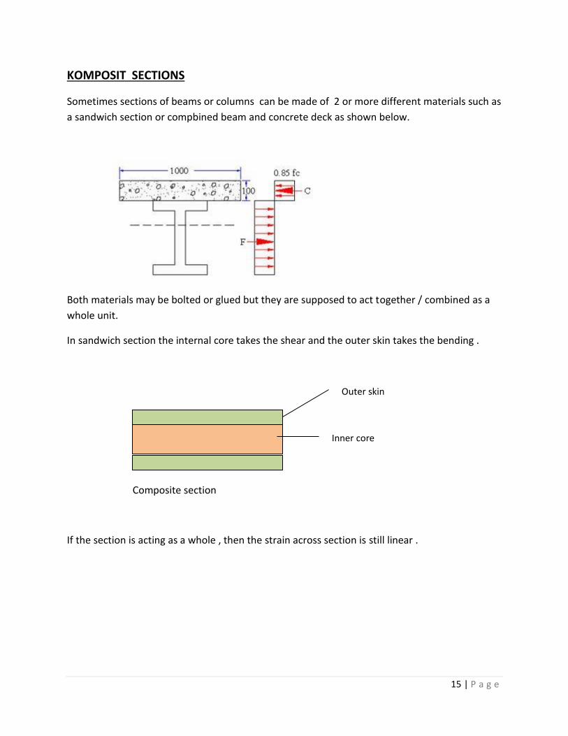
KOMPOSIT SECTIONS
Sometimes sections of beams or columns can be made of 2 or more different materials such as
a sandwich section or compbined beam and concrete deck as shown below.
Both materials may be bolted or glued but they are supposed to act together / combined as a
whole unit.
In sandwich section the internal core takes the shear and the outer skin takes the bending .
Composite section
If the section is acting as a whole , then the strain across section is still linear .
Outer skin
Inner core
16 | P a g e
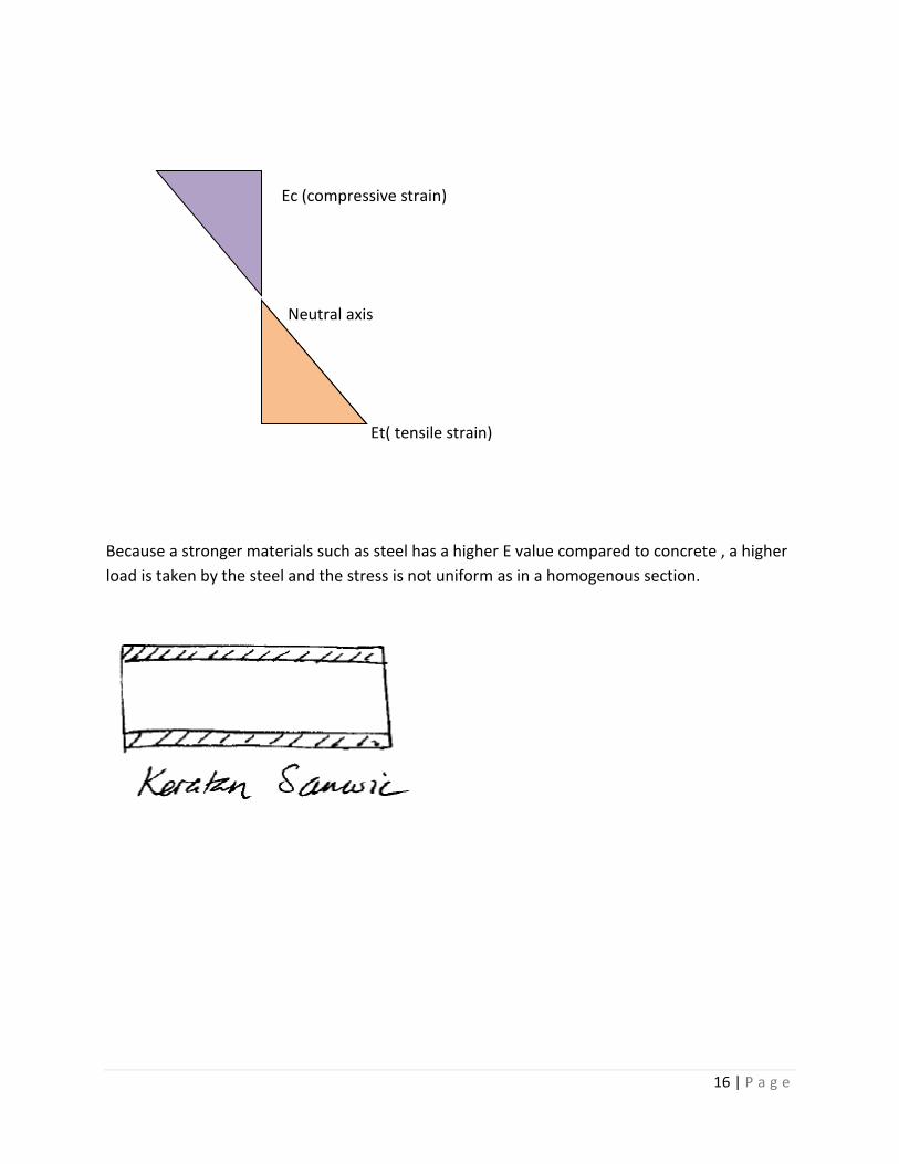
Ec (compressive strain)
Neutral axis
Et( tensile strain)
Because a stronger materials such as steel has a higher E value compared to concrete , a higher
load is taken by the steel and the stress is not uniform as in a homogenous section.
17 | P a g e
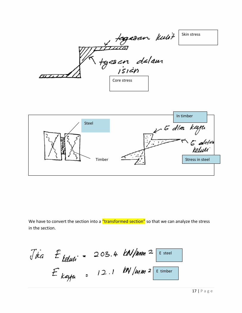
We have to convert the section into a “transformed section” so that we can analyze the stress
in the section.
Skin stress
Core stress
Stress in steel
In timber
Steel
Timber
E steel
E timber

18 | P a g e
The Modula ratio = 203.4 / 12.1 = 16.8
So in a section shown below the steel plate can be converted into a timber plate by;
B
16.8 B
timber
Steel
19 | P a g e
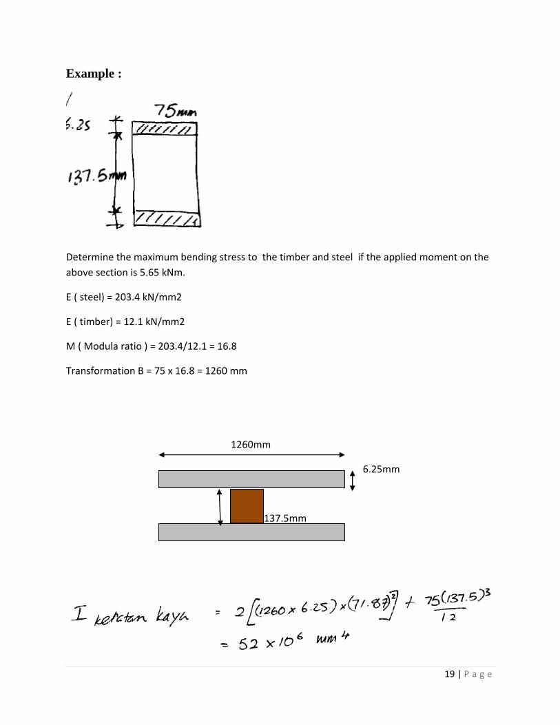
Example :
Determine the maximum bending stress to the timber and steel if the applied moment on the
above section is 5.65 kNm.
E ( steel) = 203.4 kN/mm2
E ( timber) = 12.1 kN/mm2
M ( Modula ratio ) = 203.4/12.1 = 16.8
Transformation B = 75 x 16.8 = 1260 mm
1260mm
6.25mm
137.5mm
20 | P a g e
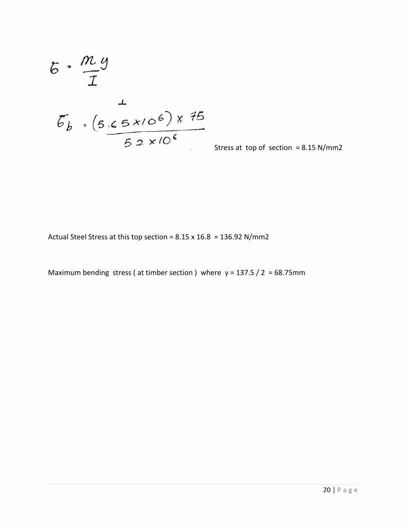
Stress at top of section = 8.15 N/mm2
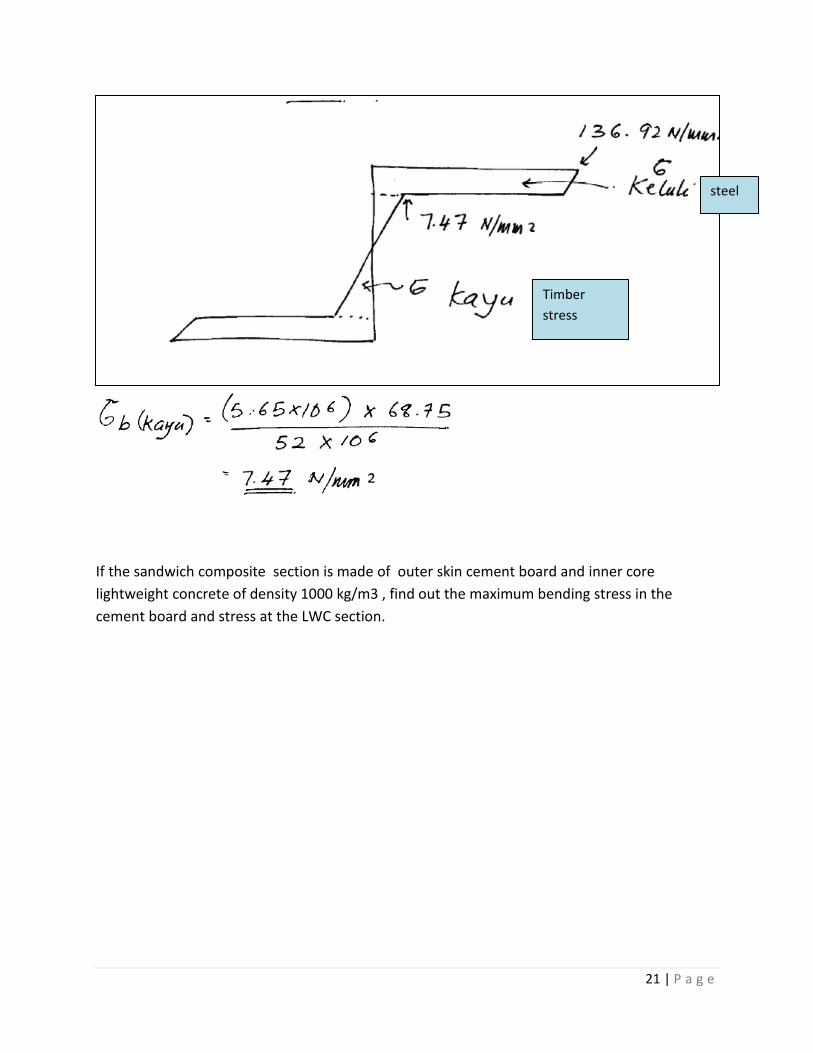
Actual Steel Stress at this top section = 8.15 x 16.8 = 136.92 N/mm2
Maximum bending stress ( at timber section ) where y = 137.5 / 2 = 68.75mm
21 | P a g e
If the sandwich composite section is made of outer skin cement board and inner core
lightweight concrete of density 1000 kg/m3 , find out the maximum bending stress in the
cement board and stress at the LWC section.
Timber
stress
steel

22 | P a g e