Embed Size (px)
DESCRIPTION
Presented at HRS Boston 2012
Citation preview
Present Solutions to the Problem of Electromagnetic Interference: Are They Good Enough?
Sergio L. Pinski, MD
Cleveland Clinic Florida
Weston, FL, USA
Presenter Disclosure Information
Boston Scientific, Medtronic, St Jude: consultant, member of speaker’s bureau
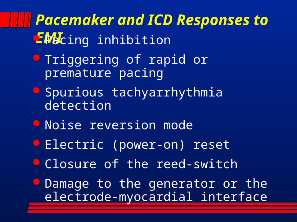
Pacemaker and ICD Responses to EMI Pacing inhibition Triggering of rapid or premature
pacing Spurious tachyarrhythmia detection Noise reversion mode Electric (power-on) reset Closure of the reed-switch Damage to the generator or the
electrode-myocardial interface
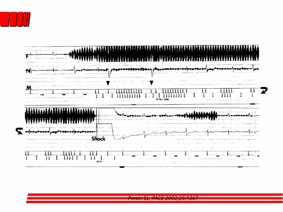
Pinski SL. PACE 2002;25:1367
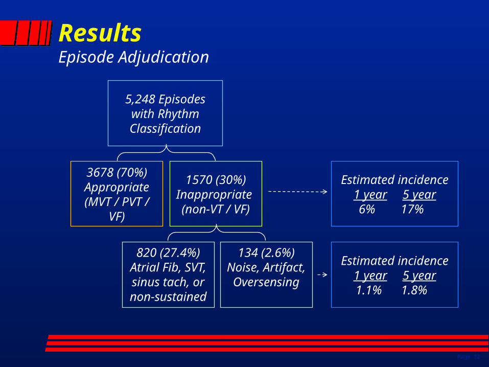
ResultsEpisode Adjudication
Page 12
5,248 Episodes with Rhythm Classification
3678 (70%) Appropriate
(MVT / PVT / VF)
1570 (30%)Inappropriate (non-VT / VF)
134 (2.6%)Noise, Artifact, Oversensing
Estimated incidence1 year 5 year
6% 17%
Estimated incidence1 year 5 year
1.1% 1.8%
820 (27.4%)Atrial Fib, SVT, sinus tach, or non-sustained
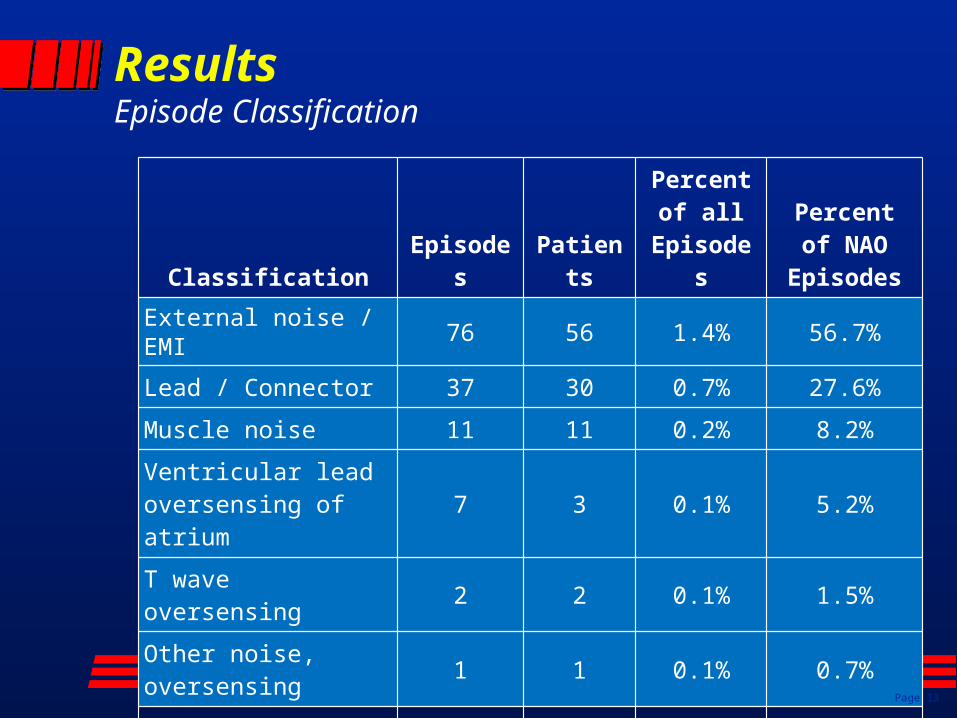
ResultsEpisode Classification
Classification Episodes Patients
Percent of all
Episodes
Percent of NAO
Episodes
External noise / EMI 76 56 1.4% 56.7%
Lead / Connector 37 30 0.7% 27.6%
Muscle noise 11 11 0.2% 8.2%
Ventricular lead oversensing of atrium
7 3 0.1% 5.2%
T wave oversensing 2 2 0.1% 1.5%
Other noise, oversensing
1 1 0.1% 0.7%
Total 134 101 2.6% 100.0%
Page 13
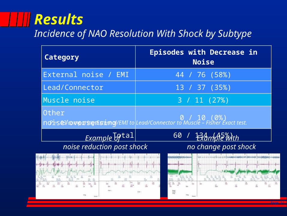
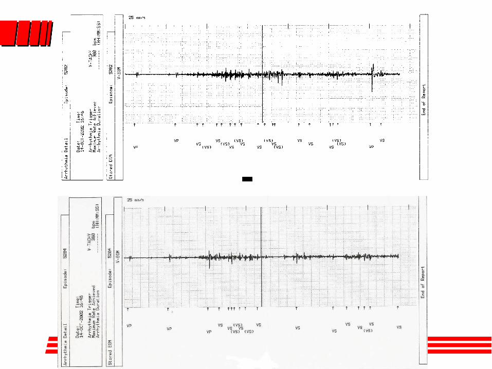
ResultsIncidence of NAO Resolution With Shock by Subtype
Category Episodes with Decrease in Noise
External noise / EMI 44 / 76 (58%)
Lead/Connector 13 / 37 (35%)
Muscle noise 3 / 11 (27%)
Other noise/oversensing 0 / 10 (0%)
Total 60 / 134 (45%)
P = .03 comparing External/EMI to Lead/Connector to Muscle – Fisher Exact test.
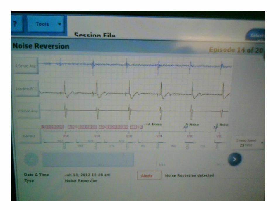
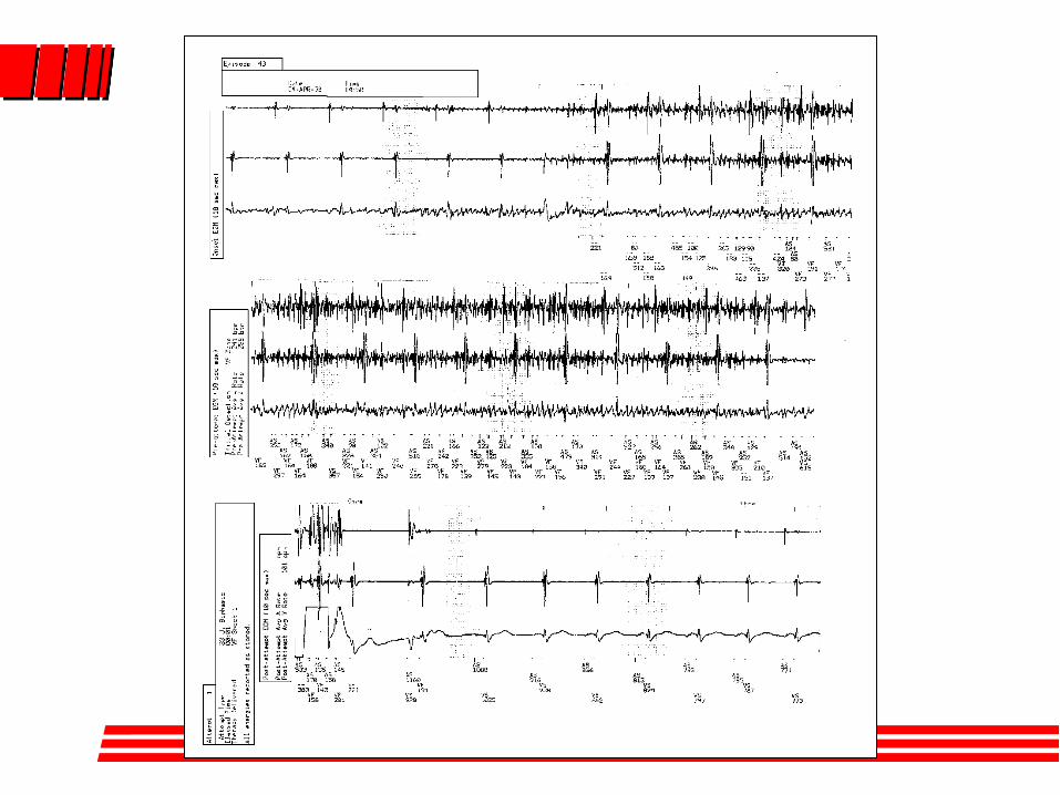
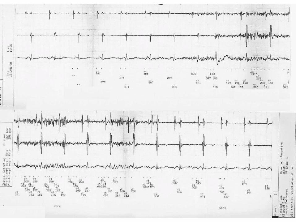
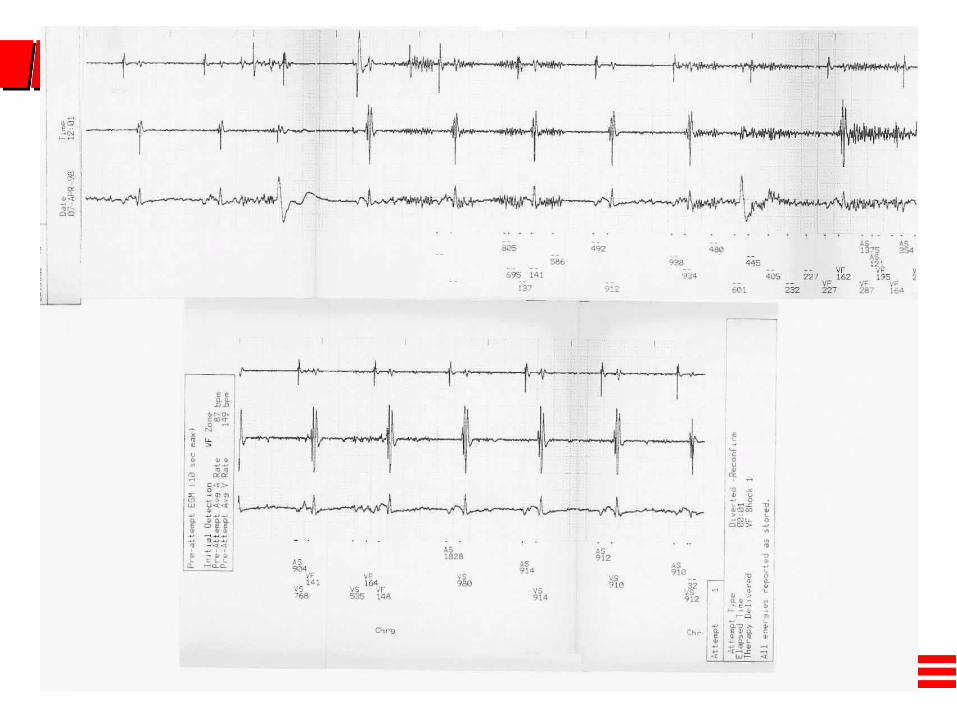
Example of noise reduction post shock
Example with no change post shock
Page 14
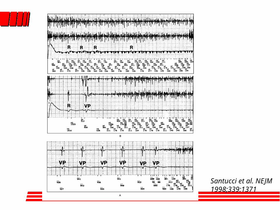
Santucci et al. NEJM 1998;339:1371
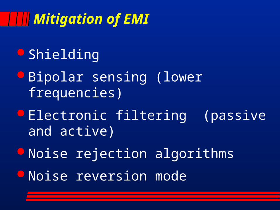
Mitigation of EMI
Shielding
Bipolar sensing (lower frequencies)
Electronic filtering (passive and active)
Noise rejection algorithms
Noise reversion mode
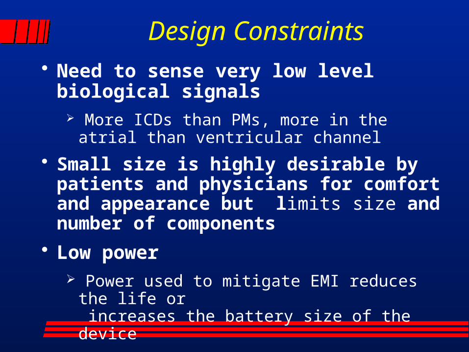
• Need to sense very low level biological signals
More ICDs than PMs, more in the atrial than ventricular channel
• Small size is highly desirable by patients and physicians for comfort and appearance but limits size and number of components
• Low power Power used to mitigate EMI reduces the life or
increases the battery size of the device
Design Constraints
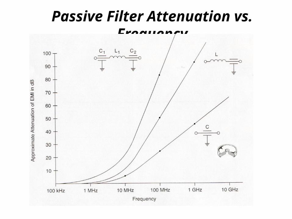
Passive Filter Attenuation vs. Frequency
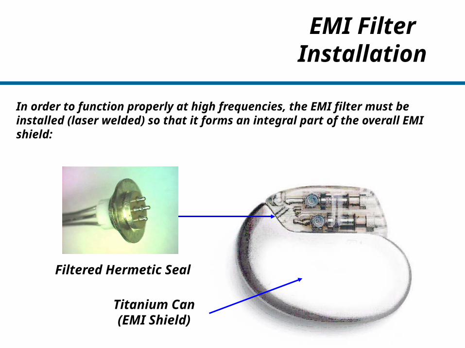
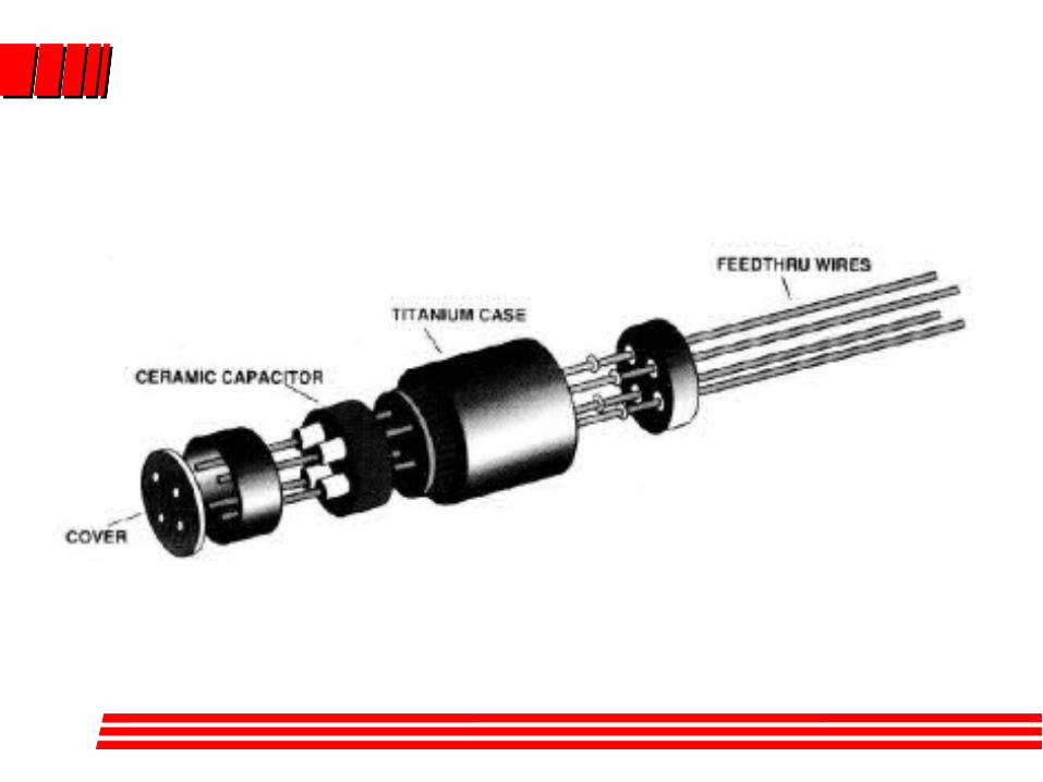
EMI Filter Installation
In order to function properly at high frequencies, the EMI filter must be installed (laser welded) so that it forms an integral part of the overall EMI shield:
Titanium Can(EMI Shield)
Filtered Hermetic Seal
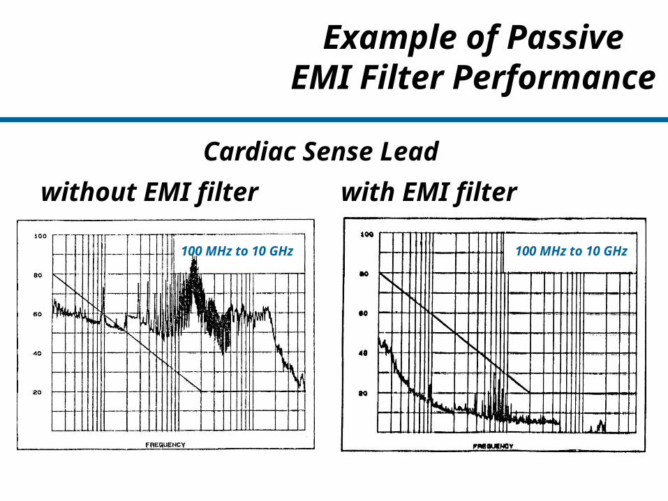
Example of PassiveEMI Filter Performance
Cardiac Sense Lead
without EMI filter with EMI filter
100 MHz to 10 GHz 100 MHz to 10 GHz
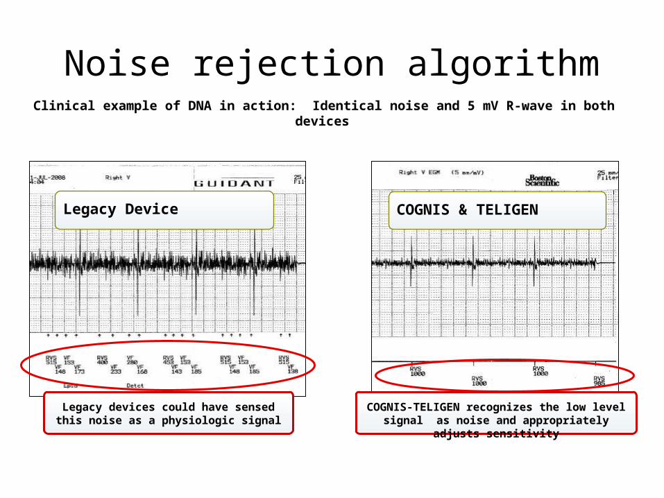
Noise rejection algorithmClinical example of DNA in action: Identical noise and 5 mV R-wave in both devices
Legacy Device COGNIS & TELIGEN
Legacy devices could have sensed this noise as a physiologic signal
COGNIS-TELIGEN recognizes the low level signal as noise and appropriately adjusts sensitivity
Page 25
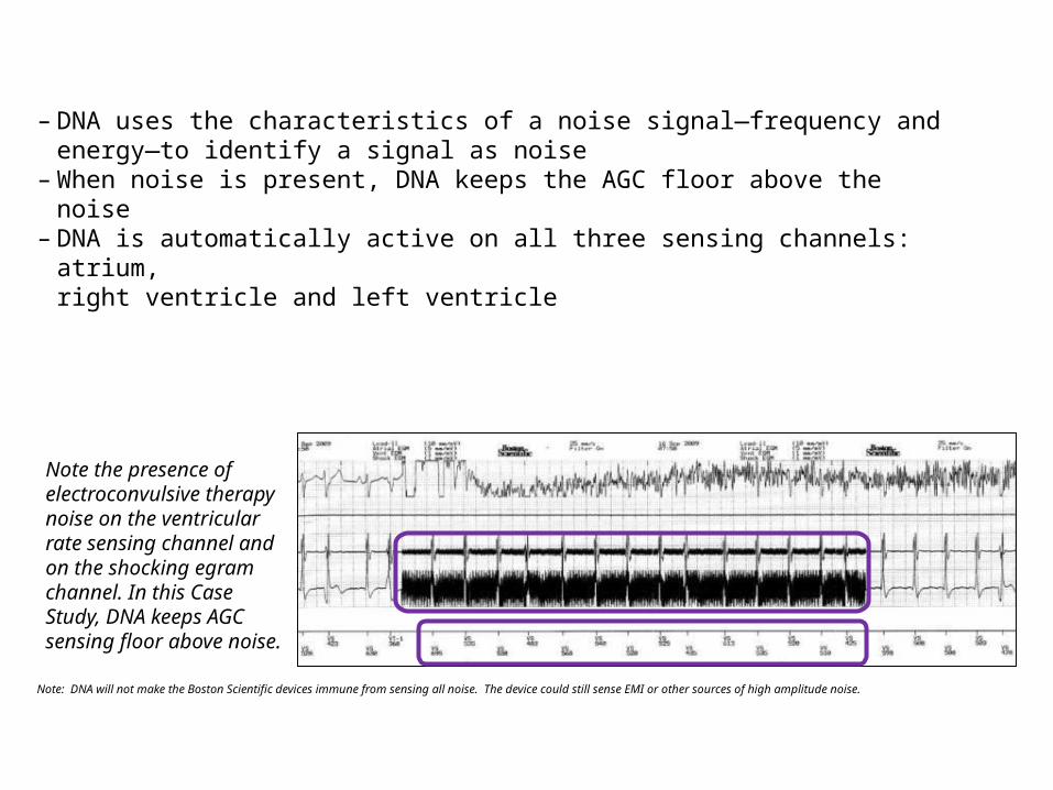
– DNA uses the characteristics of a noise signal—frequency and energy—to identify a signal as noise
– When noise is present, DNA keeps the AGC floor above the noise – DNA is automatically active on all three sensing channels: atrium,
right ventricle and left ventricle
Note: DNA will not make the Boston Scientific devices immune from sensing all noise. The device could still sense EMI or other sources of high amplitude noise.
Note the presence of electroconvulsive therapy noise on the ventricular rate sensing channel and on the shocking egram channel. In this Case Study, DNA keeps AGC sensing floor above noise.

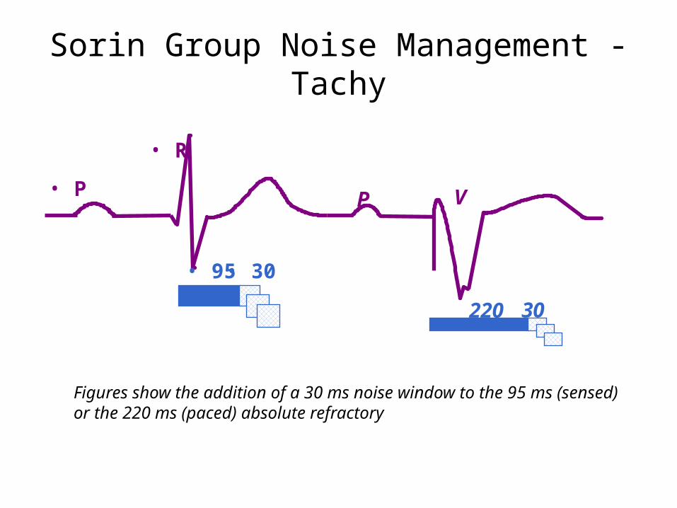
Sorin Group Noise Management - Tachy
• Since 1996 Sorin Group/ELA has had a ventricular noise circuit in all its ICDs
• Based on the premise that human beings cannot sustain intervals in the 188-125 ms range. If intervals consistently in that range are seen they are most likely the result of EMI (noise).
• After several retriggered windows Ventricular Sensitivity is decreased by 0.2 mV on each retriggered window until not retriggered. This process is done on a beat to beat basis
• The circuit is turned off for 15 cycles with an interval of 400 ms to 188 ms to assure arrhythmia detection
• On the 16th cycle, if there has not been an interval larger than 188 ms the noise circuit is turned on again
• Atrial noise circuit similar to Brady function
Sorin Group Noise Management - Tachy
• P
• R
• 95• 30
P V
220 30
Figures show the addition of a 30 ms noise window to the 95 ms (sensed) or the 220 ms (paced) absolute refractory
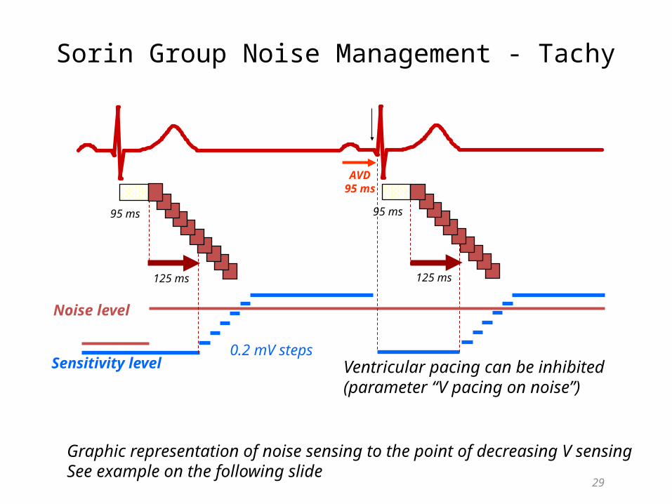
Sorin Group Noise Management - Tachy
29
Noise level
Sensitivity level0.2 mV steps
95 ms 95 ms
125 ms 125 ms
AVD95 ms
Ventricular pacing can be inhibited (parameter “V pacing on noise”)
Graphic representation of noise sensing to the point of decreasing V sensingSee example on the following slide
30
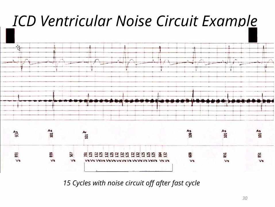
ICD Ventricular Noise Circuit Example
15 Cycles with noise circuit off after fast cycle
30
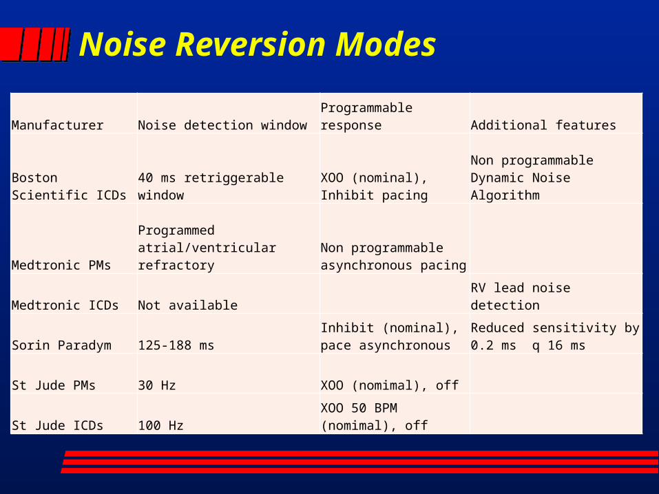
Noise Reversion Modes
Manufacturer Noise detection windowProgrammable response Additional features
Boston Scientific ICDs 40 ms retriggerable window
XOO (nominal), Inhibit pacing
Non programmable Dynamic Noise Algorithm
Medtronic PMsProgrammed atrial/ventricular refractory
Non programmable asynchronous pacing
Medtronic ICDs Not available RV lead noise detection
Sorin Paradym 125-188 msInhibit (nominal), pace asynchronous
Reduced sensitivity by 0.2 ms q 16 ms
St Jude PMs 30 Hz XOO (nomimal), off
St Jude ICDs 100 HzXOO 50 BPM (nomimal), off
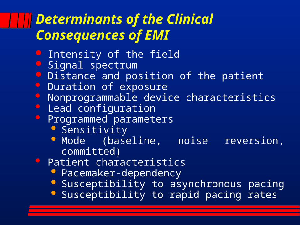
Determinants of the Clinical Consequences of EMI Intensity of the field Signal spectrum Distance and position of the patient Duration of exposure Nonprogrammable device characteristics Lead configuration Programmed parameters
Sensitivity Mode (baseline, noise reversion, committed)
Patient characteristics Pacemaker-dependency Susceptibility to asynchronous pacing Susceptibility to rapid pacing rates
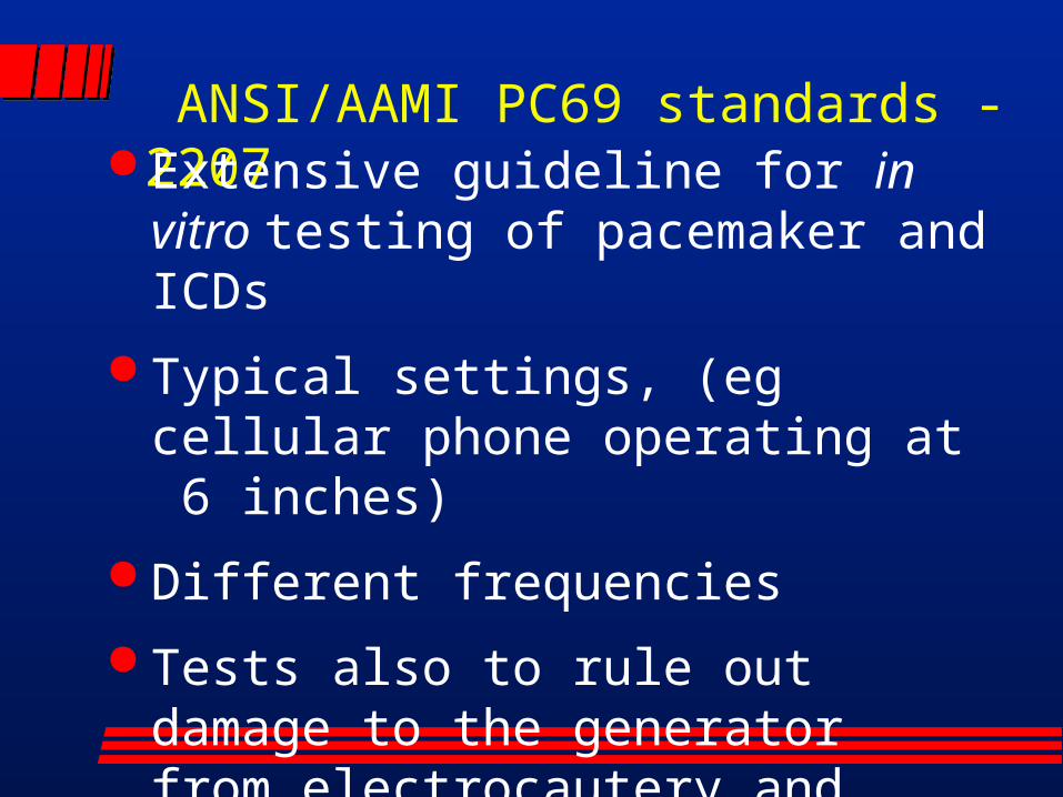
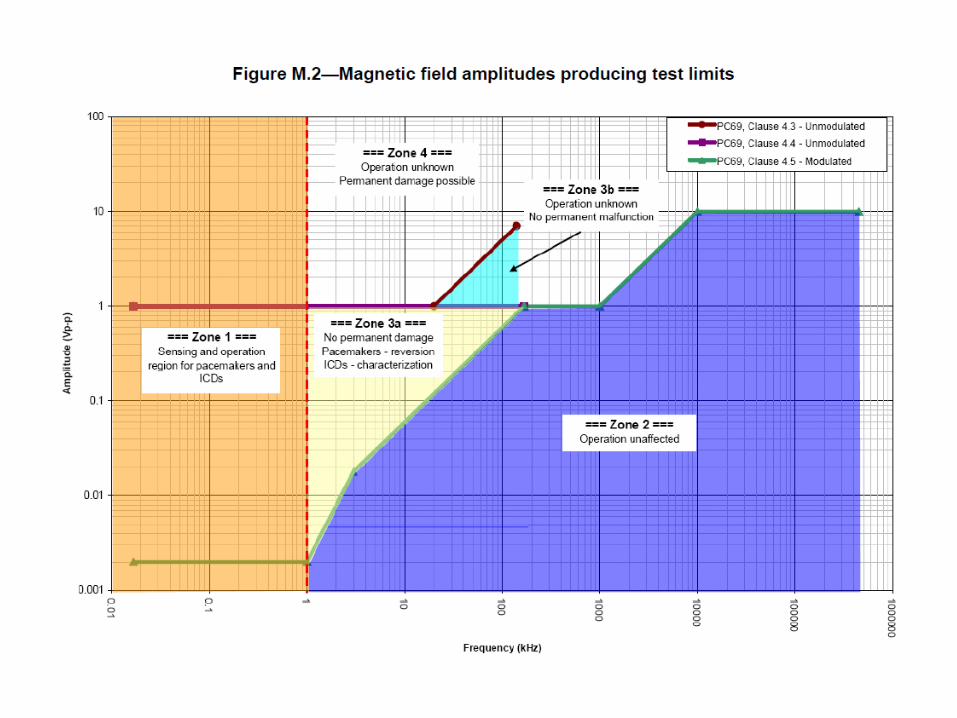
ANSI/AAMI PC69 standards -2207 Extensive guideline for in vitro testing of pacemaker and ICDs
Typical settings, (eg cellular phone operating at 6 inches)
Different frequencies
Tests also to rule out damage to the generator from electrocautery and external defibrillation
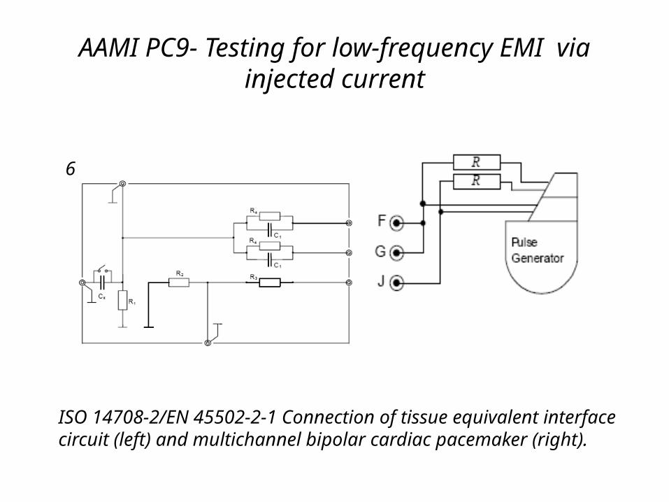
AAMI PC9- Testing for low-frequency EMI via injected current
6
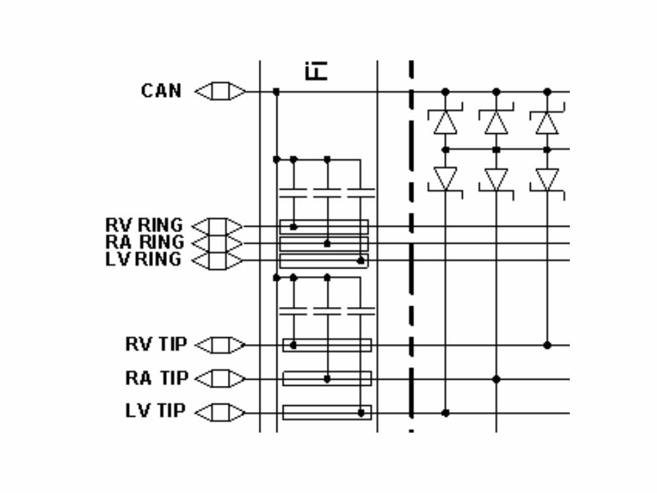
ISO 14708-2/EN 45502-2-1 Connection of tissue equivalent interface circuit (left) and multichannel bipolar cardiac pacemaker (right).
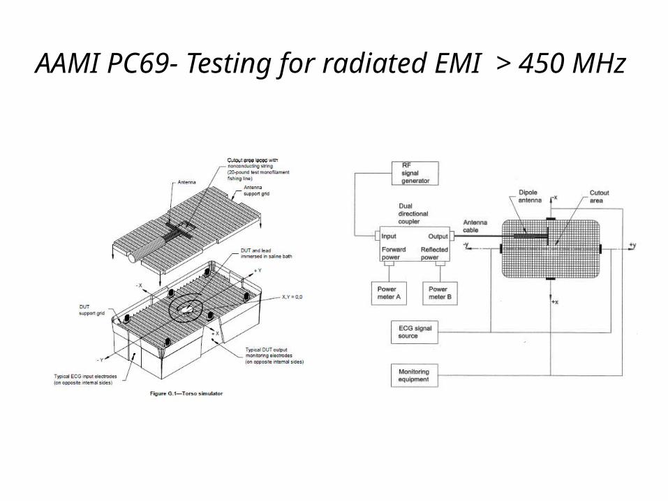
AAMI PC69- Testing for radiated EMI > 450 MHz
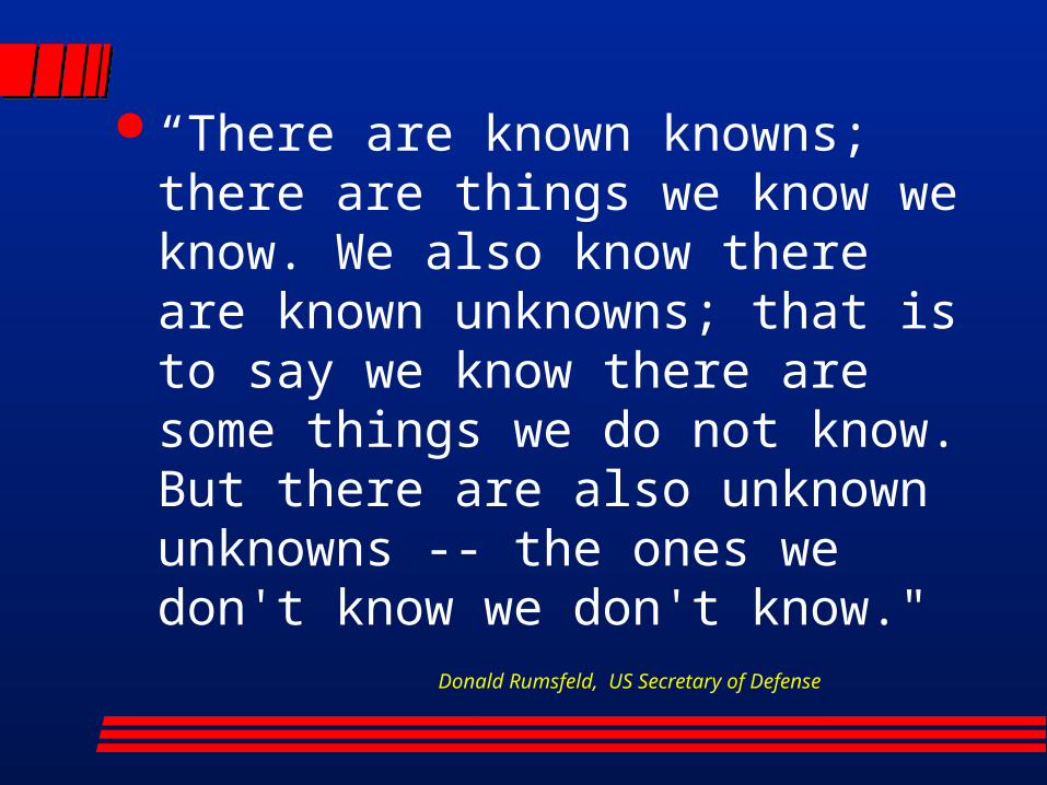
“There are known knowns; there are things we know we know. We also know there are known unknowns; that is to say we know there are some things we do not know. But there are also unknown unknowns -- the ones we don't know we don't know."
Donald Rumsfeld, US Secretary of Defense
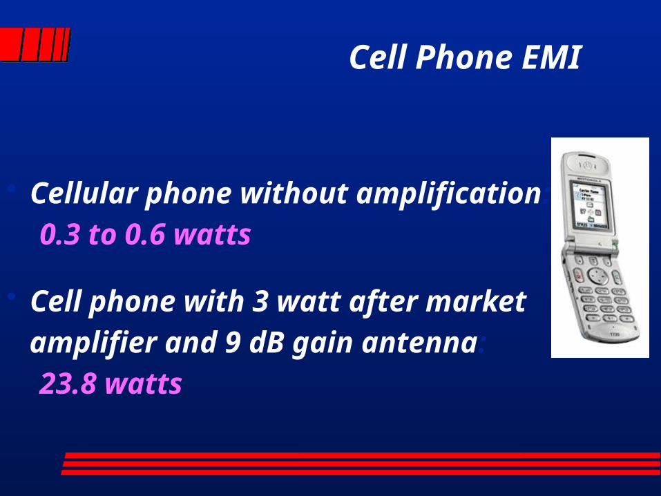
Cell Phone EMI
• Cellular phone without amplification:
0.3 to 0.6 watts
• Cell phone with 3 watt after market
amplifier and 9 dB gain antenna:
23.8 watts
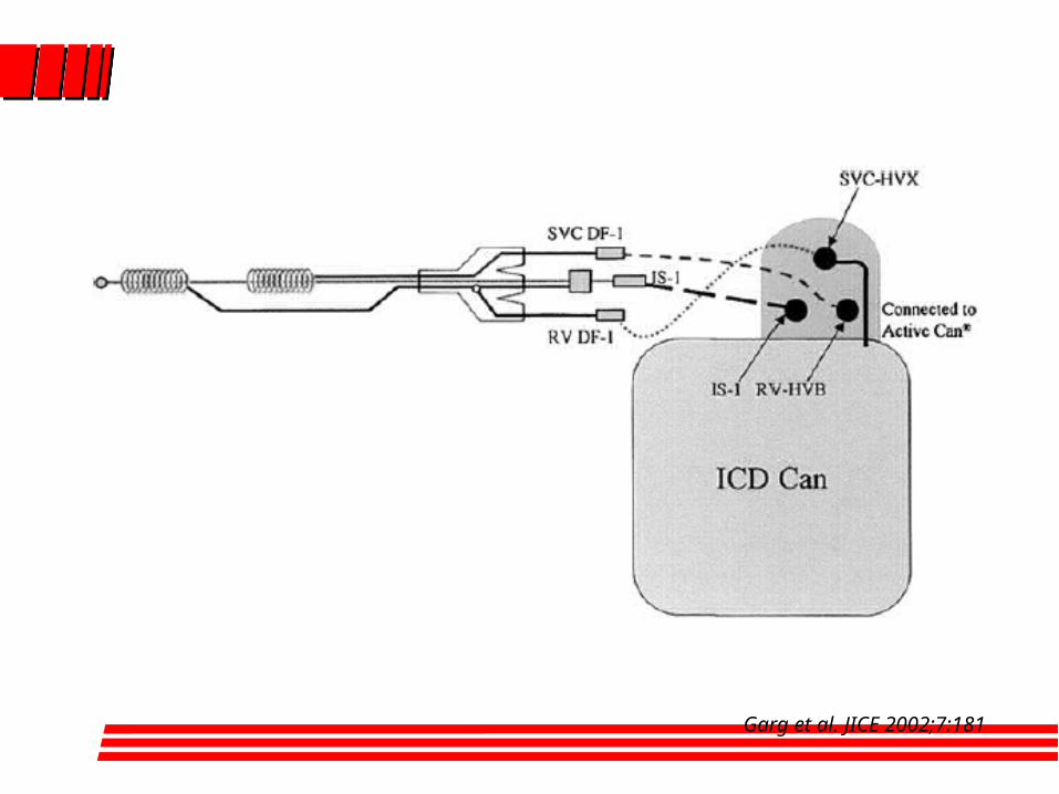
Garg et al. JICE 2002;7:181
Kill the parasites that make you ill with
Para Zapper ™ improved Hulda Clark parasite zapper
In her book, The Cure For All Diseases, Dr. Clark describes how certain parasites affect our health and how we can improve our health by killing them using a parasite zapper . Since this book
was first published, many individuals have discovered that zappers really do work. There are thousands of zappers sold
arround the world , most of them work, killing bacteria, protozoa, and other parasites. We offer several different models and
options to suit your parasite zapper requirements. Our zappers are offered to provide better quality at best price.
Better Zapper Made in the USA of high quality parts. Better Dual Frequency zapper (30 kHz)and (2.5 kHz)
Better Top quality wires and plugs, more compact Long battery life: Power LED
Best instruction manual available according to users. Includes sample startup supplies. Sea Salt, etc.
Best zapper Price, Quality, Reliability, Performance .
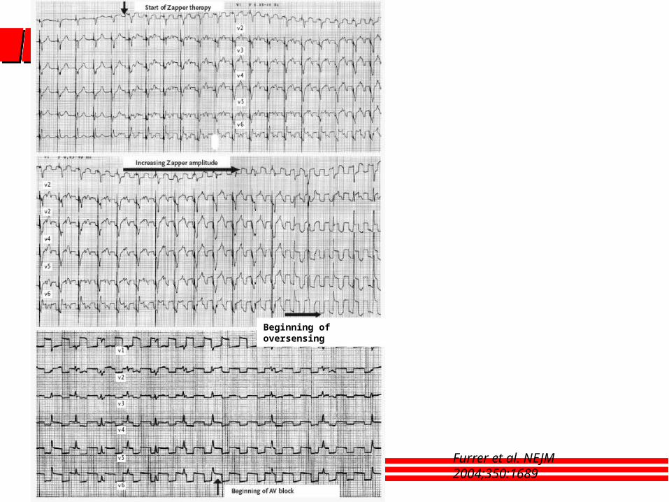
Furrer et al. NEJM 2004;350:1689
Beginning of oversensing

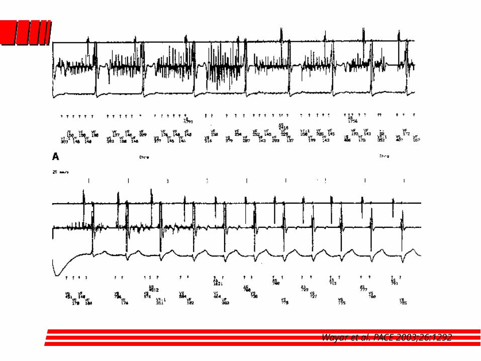
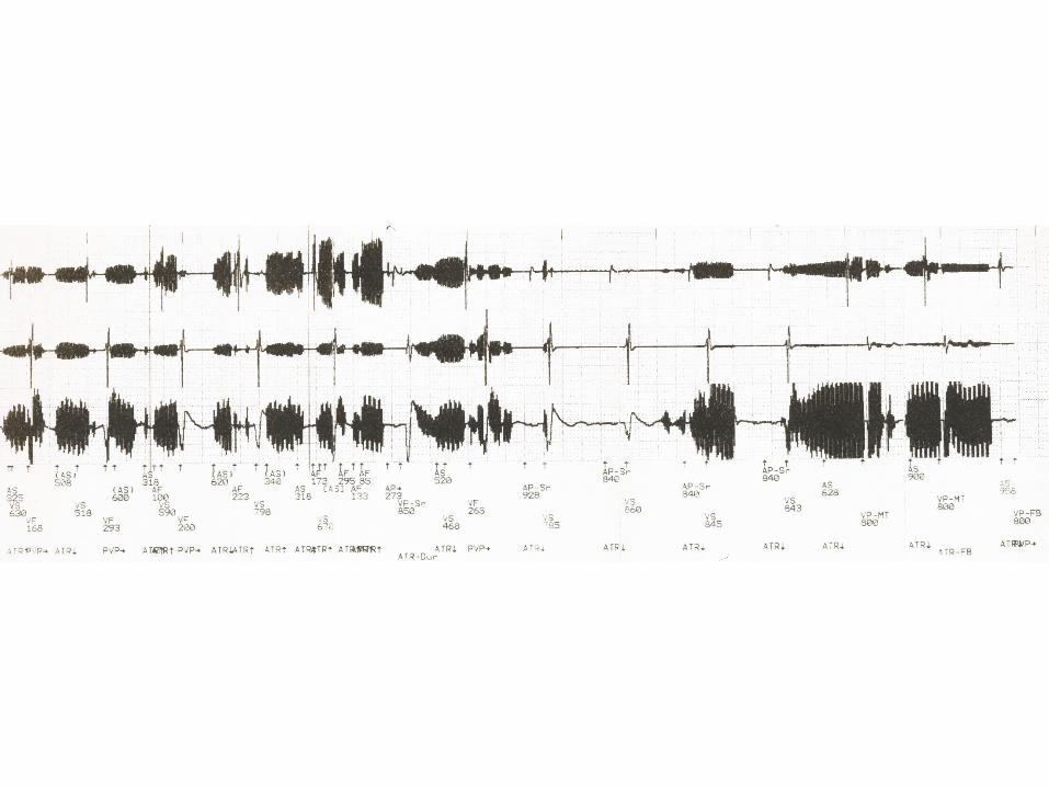
Wayar et al. PACE 2003;26:1292
Conclusions
Full electromagnetic compatibility has not been achieved yet (and may never be)
Multiple potential sources of EMI exist in daily life, work and medical environments
Conclusions
Improvement in sensing circuits and algorithms together with better awareness of sources of electromagnetic interference have already reduced EMI
Continous surveillance is needed as new emitting sources are introduced
Conclusions
Sources of further minimization
Continuous improvements in device engineering
Awareness of manufacturers of emitters
Patient and public education