Embed Size (px)
Citation preview

Pacemakers: Some Basic and Some Not-So-Basic Concepts
Muzaffar Ali, DMSKIMS SOURA
Pacemaker Components• Battery• Primary power source• Mercury zinc batteries were used in early pacemakers• These batteries produced gasses over time that required venting. • This resulted in fluid leakage into the pacemaker at times that
caused electrical shorting and premature device failure• Mercury zinc batteries have a fairly short useful life • Have an abrupt drop in voltage as they become depleted.• This makes predicting the pending failure of the batteries
difficult. • No devices of this type are currently in use

• Nuclear pacemakers use a very small amount of radioactive element plutonium to generate heat
• The heat is converted into electricity by a thermocouple• These devices had very long service lives (some were guaranteed
for 72 years)• They were large • Created problems when travelling between states and countries
due to the presence of their radioactive fuel• They must also be removed at the time of death and returned for
proper disposal• Nuclear power sources became obsolete when the long-lived
lithium batteries were developed


• Rechargeable pacemakers use a nickel-cadmium battery that must be charged each week.
• The recharging is done using a method known as “inductive coupling”.
• A coil is placed on the skin over the pacemaker that transfers energy to a coil within the device via electromagnetic waves.
• The Pacemakers are large and became obsolete with newer technology

• Lithium iodine is currently the predominant power source being used in pacemakers today
• A long shelf life and high energy density• The self-discharge rate is very low resulting in a
long shelf life• It has a stable voltage through much of the useful
life, then tapers down in a gradual and predictable manner

Circuitry
• Highly complex and integrated microprocessor based systems
• Large data storage capabilities• Includes total number of cardiac events, the rate of
these events, whether these were paced or intrinsic, and high rate episodes
• The newest devices have the ability to store intracardiac electrograms and function as event monitors with the ability to playback the paced or sensed events

Connector Block
• Also referred to as the “header”• The means by which the pacemaker wire is
connected to the pacemaker circuitry.• Many different sizes and styles of connector
blocks.• Most pacemakers use setscrews


• Some connectors do not use any setscrews• These have spring connectors for all of the
electrical connections and a mechanism for gripping the lead body to hold it in place.
• The advantage to this system is that it makes the electrical connection “automatic”,
• Does not rely on the physician to make a secure connection with a screw

Leads
• More than simple “wires”.• They are complex and highly engineered devices
that consist of many components


• Electrodes • Electrically active surfaces• Delivers an electrical stimulus, detects intrinsic
cardiac electrical activity, or both

• Material used:• elgiloy• polished platinum• microporous platinum (platinized or “black”
platinum)• macroporous platinum (mesh)• iridium-oxide• platinum-iridium• titanium nitride

• Modern electrodes elute an anti-inflammatory drug such as dexamethasone
• Eluting such a drug at the electrode surface reduces the amount of acute inflammation and fibrosis at the electrode myocardial interface.
• Greater charge density• Reduces current required to stimulate• Lower battery drain• Increased longevity

• Anode/ring electrode• Larger than cathode• Positioned about 1cm or more back from the
cathode• Changes in the spacing between these two
electrodes affect the sensing function, with closer spacing minimizing oversensing of electrical signals from other sources

• Insulation• One of the most important components• Prevents electrical shorting between the conductor
coils within the lead, • Prevents stimulation of tissues other than the heart,• Allows smooth passage of the lead into the vein.• Failure of the insulation may result in a number of
different problems, the most important of which is failure to pace.

• Insulation types:• silicone / silastic• 55D polyurethane• 80A polyurethane• Other polyurethanes• Teflon “coated coil” technology

• Metal ion oxidation (MIO)• Environmental stress cracking (ESC)• Coated coil insulation:insulating coat to each
individual filament of the wire, that are then wound together in a design known as coradial construction. The whole wire is then covered with a standard insulator.

• Conductor Coil: carries the electrical impulse from the pacemaker to the heart and the signal from the heart back to the pacemaker


• Fixation:• “kerplunk” leads• tines• fins• fixed extended helix• retractable helix


Connector
• Portion of the lead that connects it to the pacemaker• Many types of connectors• All manufacturers have agreed upon the International
Standard-1 (IS-1)• IS-1: 3.2 mm wide, sealing rings, short pin, uni/bipolar• An IS-1 lead from one manufacturer should be
compatible with an IS-1 connector block of another manufacturer
• IS-4


Polarity

• Simpler and more reliable single coil lead construction.
• Much easier to see the pace artifact• Bipolar electrograms represent the difference in
potential recorded between two closely spaced intracardiac electrodes.
• Due to the close spacing of two typically small electrodes, far-field signals (i.e.,signals not generated by the tissue the lead electrode is in contact with) are smaller and thus more easily rejected

• More resistant to electrical interference caused by skeletal muscle activity or electromagnetic interference (EMI) relative to unipolar systems
• At higher output settings one may have stimulation of the pocket around the pacemaker in a unipolar system
• Pacing artifact: makes determination of function and malfunction more difficult, not uncommon to see a pacemaker programmed to pace in the unipolar polarity and to sense in the bipolar polarity.

Pacing threshold
• Minimum amount of energy required to consistently cause depolarization
• Measured in terms of both amplitude (the strength of the impulse) and the duration of time for which it is applied to the myocardium (pulse width), measured in msec
• Method of measuring threhold• Wedensky effect• Standard method for threshold testing


Sensing: ability of the device to detect an intrinsic beat of the heart (mV)
Higher values are less senstive

• The pacing lead does not see a QRS or P-wave as we see it on the surface ECG
• It sees an intracardiac electrogram that is more like a “spike”


Slew rate
• Pacemaker does not use the entire signal that is present
• The “raw” electrical signal is filtered to eliminate a majority of noncardiac signals as well as parts of the cardiac signal that are not needed
• Slew rate: quality of the sensed signal• Slope of the intrinsic signal and is measured in
volts/sec


Implant and postimplant values

The Rule of 60,000
• 60,000 Rule: 60,000 msec in a minute• 60,000/Heart rate = Interval in milliseconds• 60,000/Interval in milliseconds = Heart rate• Examples:• Heart rate = 70 bpm• 60,000/70 = 857 msec cycle length
• Cycle length = 857 msec• 60,000/857 = 70 bpm

Automatic interval

Escape Interval

Refractory Period

• The reason for having a refractory period in a ventricular pacemaker is to prevent sensing of the evoked QRS and T-wave that occurs immediately after the paced event
• In atrial pacemakers the refractory period also prevents sensing of the far-field R-wave or T-wave
• Blanking period

Hysteresis

• Useful in patients with ventricular pacemakers and sinus rhythm that have infrequent pacing needs, thus minimizing the loss of atrio-ventricular synchrony.

Fusion


Pseudo-fusion: Pace OP doesn’t affect dep or rep
Pseudopseudo fusion beat

Latency
• Pacemaker output spike occurs and captures, however there is a period (latent period) of isoelectric baseline prior to the QRS or P wave following the spike.
• Usually associated with metabolic derangements


AVI:The period of time in milliseconds between a paced or sensed atrial event until the paced ventricular event.

Differential AV interval

Adaptive AVI interval

Atrial Escape Interval (AEI)
• Maximum period of time that can elapse between the last sensed or paced ventricular event and the next atrial event
• If no intrinsic atrial beat occurs by the end of the AEI, an atrial pace output will be delivered
• AEI = Base pacing rate minus AVI


Post Ventricular Atrial Refractory Period (PVARP)
• Atrial refractory period that begins with each paced or sensed ventricular event
• It turns off the atrial amplifier to prevent the atrial lead from sensing the ventricular depolarization (QRS and T-wave)
• Prevents sensing of retrograde P-waves should a PVC occur


Total Atrial Refractory Period (TARP)
• AVI + PVARP = TARP• No atrial sensing for the purpose of tracking
occurs during the AVI and during the PVARP• Atrial event occurring during TARP will not start
an AVI• The TARP limits the upper rate limit of the
pacemaker

Upper Rate Limit (URL)
• Maximum tracking rate (MTR) or the• Maximum tracking interval (MTI)• Programmable feature• The maximum rate at which the pacemaker will allow
the ventricle to pace• Depends on TARP• URL = 60,000/TARP• The URL may be separately programmable for
tracking P-waves and for the upper sensor driven rate

Ventricular Blanking Period• Follows immediately after an atrial pacing pulse is delivered.• Prevents the ventricular sensing channel from sensing the
large atrial pulse• Should ventricular sensing of the atrial output occur, the
ventricular output pulse will be inhibited and the patient will not have a ventricular beat: “crosstalk”
• The blanking period is usually set in the range of 12-50 msec• Long blanking periods are very effective against crosstalk but
limit the ability of the pacemaker to sense normal or premature ventricular beats.

Upper rate behavior
• Seen any time a mode is used that allows the ventricle to be paced as the result of an atrial sensed event ie intrinsic to DDD & VDD
• Occurs when the patient’s atrial rate is faster than the URL and/or exceeds the atrial sensing limits imposed by the programmed TARP.
• When the patient’s atrial rate reaches the limits imposed by the pacemaker in a patient with high degree AV block, one of two types of responses can be seen

Block
• Same way as second degree (Mobitz-II) AV block.• 2:1 pacemaker block will occur when the
maximum tracking rate is set to the limits imposed by the TARP (PVARP + AVI)
• With TARP= 500 msec(120bp,) and URL=120/min. If atrial rate is >120, everyother P wave will fall into PVARP and will not be sensed resulting in 2:1 block and symptoms

TARP is 600 ms ie URL 100 bpm. Once the atrial rate exceeds 100 bpm, P-waves begin to fall into the PVARP and are not sensed creating a 2:1 block

Pseudo-Wenckebach
• Appears like classic Mobitz-I• Occurs when the URL is programmed to a rate
lower than the limits imposed by the TARP• TARP=400 msec limiting the upper tracking rate
to 150 bpm. Programming a URL to 100 bpm would result in Wenckebach behavior for atrial rates that exceed the URL of 100 bpm but are below the 2:1 block rate of 150 bpm
• Wenckebach interval

• The pacemaker delays the ventricular output to prevent pacing the ventricle faster than allowed by the programmed URL.
• Because of the delayed ventricular pacing, the next P wave falls even earlier into the next cardiac cycle and the AVI extension is even greater
• Because the ventricular output is delayed, the AVI appears prolonged giving a Wenckebach appearance
• Each successive AVI will lengthen until a P-wave falls into the atrial refractory period and is therefore not sensed. This P-wave will not start an AVI, and thus the next QRS is “dropped”.


• It is preferable to program a device so that Wenckebach behavior will occur prior to the 2:1 block behavior.
• This allows the patient some warning before the heart rate will drop abruptly

• Methods have been developed to minimize the effect of abrupt onset 2:1 blocking
• Rate Smoothing: limits changes in R to R intervals to a percentage of the previous interval. For example, by setting this parameter to a value of 6%, one cardiac cycle will not be allowed to differ from the previous one by more or less than 6%. Also be useful to reduce the pauses seen in patients with frequent PVCs and to reduce the risk of tracking retrograde atrial beats.

• Fallback Response: allows the pacemaker rate to gradually decrease after the upper rate is reached. It is usually programmable as to the lower rate to which it will fall and the period of time it will take to get to the fallback rate

• Sensor Driven Rate Smoothing: The pacing rate will drop to the rate indicated by the activity sensor at that point in time.
• A patient has a DDDR pacemaker programmed to an upper rate and 2:1 block rate of 120 bpm. If the patient is running and the sensor rate indicates a pacing rate of 115 bpm while the atrial rate is 125 bpm, the device will act as if the lower rate limit is 115. The pacing rate will vary between the URL of 120 and the sensor indicated rate of 115 until the native atrial rate falls below the URL

Positive AV Interval Hysteresis• Autointrinsic Conduction Search• AV Search• Functional mode switching• Narrow nonpaced QRS achieves a greater stroke volume
than a paced left bundle branch block (LBBB) pattern QRS• Adds an additional interval onto the programmed AVI for
one cycle. If a sensed QRS occurs during this prolonged AV interval, the device maintains the longer interval. If the device does not sense a QRS during the longer interval, pacing continues at the normal programmed AVI

Negative AV Interval Hysteresis

Rate Drop Response
• The pacemaker is set with a lower pacing rate and a therapeutic pacing rate
• Also set with a heart rate zone and a rate of change within that zone
• Patients who have autonomic dysfunction with a cardioinhibitory response alone, or combined with a vasodepressor response


Sleep Mode / Circadian Response• Not physiologic to maintain usual rates when sleeping• Rationale behind features designed to slow the rate during
periods of inactivity or sleep• A common method of accomplishing this goal is the use of a
clock within the pacemaker.• One can set the current time, the patient’s normal waking
time and normal bedtime and a separate sleep rate is then programmed.
• If the patient gets up and becomes active during the designated sleep time, the activity sensor notes the patient movement and overrides the sleep rate

• A patient’s sleep time may vary day to day• Patients may nap at odd hours during the day• Patients and their pacemakers cross time zones but the
internal pacemaker clock has no way of knowing this.• Another feature uses the variability of patient activity as
determined by the activity sensor. The pacemaker notes inactivity of the patient after a period of time. It will then allow the rate to drop to the sleep rate. As the patient becomes active again, the pacemaker resumes the regular lower rate limit. This algorithm has the advantage of being patient based rather than clock based.

Automatic Mode Switching
• Limitation imposed when utilizing the DDD or VDD based modes in patients with intermittent atrial tachyarrhythmias
• Use of the DDI or DVI modes can prevent this, patients with AV block cannot track the atrium when the patient is in sinus rhythm.
• Allows the pacemaker to actually change it’s mode from tracking to nontracking mode
• from DDD, DDDR, VDD or VDDR to either DDI, DDIR, VVI, VVIR

• DDDR devices can utilize the sensor to evaluate whether the atrial rhythm is appropriate (such as sinus tachycardia due to exercise) or inappropriate (such as atrial fibrillation) for a given level of activity.
• If a rapid atrial rate is seen at a time when the sensor indicates that the patient is at rest, the atrial rhythm is classified as pathologic.
• The pacemaker then converts to VVIR until the atrial rate drops into the “physiologic range” again at which time DDDR function is restored

• The most common approach to mode switching does not require a sensor.
• A separately programmable “atrial tachycardia detection rate” (or “mode switch rate”) is selected
• If the atrial rate exceeds the mode switch detection rate for a given period of time or a specific number of beats, the device will switch to a nontracking mode.
• It will switch back when the atrial rate drops back into the normal range

Atrial Fibrillation Suppression Algorithms
• PACs with the resulting sinus pause may allow the atrium to become unstable and thereby predispose to the development of PAF
• These algorithms primarily attempt to suppress the PACs by overdrive pacing them, attempting to pace the atrium 100% of the time.
• Rate smoothing

Automatic Polarity Change
• What happens when a lead breaks or the insulation fails
• If an inner conductor coil (cathode) fracture occurs in a bipolar lead, the lead must be replaced
• If the outer coil (anode) fractures on this type of lead, a pacemaker with programmable polarity may be reprogrammed to the unipolar configuration thus bypassing the failed coil

• By changing polarity, the pacemaker can become the anode and there is no need for the outer coil of the lead.
• The same can be done if the lead impedance falls to a low level on a bipolar lead indicating a failure of the insulation between the two conductors
• Changing to unipolar polarity prevents a “dead short” between the two coils

Noncapture
• Identified by the presence of pacemaker pulse artifact without capture in the appropriate chamber following the impulse

Causes of noncapture• High capture threshold• Inappropriate programming to a low output or pulse width• Lead dislodgment• Lead fracture• Lead insulation failure• Loose lead connection to pacemaker• Low battery output• Severe metabolic imbalance• Threshold rise due to drug effect• “Pseudo-noncapture” (pacing during the myocardial
refractory period due to undersensing of the preceding complex

Runaway pacemaker

Undersensing
• Recognized by the presence of pulse artifact occurring after an intrinsic event that occurs, but does not reset the escape interval
• The pace output may or may not capture depending on where in the cardiac cycle the pace output falls

Causes of undersensing• Poor lead position with poor R-wave or P-wave amplitude• Lead dislodgment• Lead fracture• Lead insulation failure• Lead perforation of the myocardium• Severe metabolic disturbance• Defibrillation near pacemaker• Myocardial infarction of tissue near electrode• Ectopic beats of poor intracardiac amplitude• Inappropriate programming• Magnet application

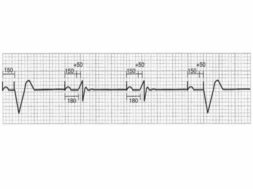
Oversensing
• Inappropriate inhibition of the pacemaker• May be seen as total inhibition of output, or as
prolongation of the escape interval• Myopotentials are a common cause of oversensing
seen predominately in unipolar pacemakers, and is usually caused by sensing noncardiac muscle activity
• Myopotentials are typically caused by arm movements or lifting for prepectoral implants


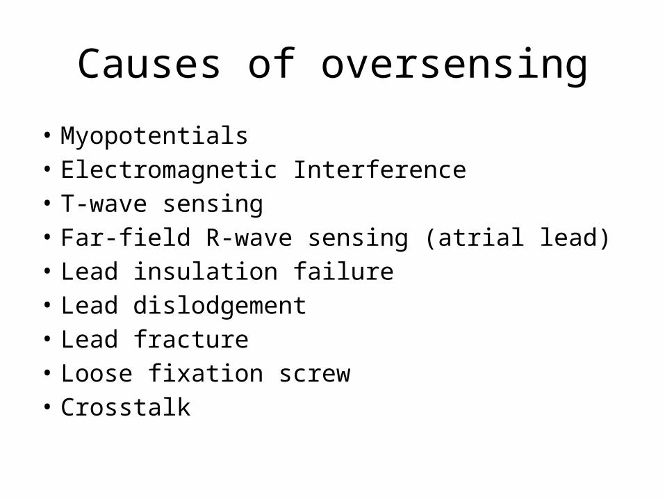
Causes of oversensing
• Myopotentials• Electromagnetic Interference• T-wave sensing• Far-field R-wave sensing (atrial lead)• Lead insulation failure• Lead dislodgement• Lead fracture• Loose fixation screw• Crosstalk

Pacemaker Syndrome
• Can occur in patients with sinus rhythm who receive VVI pacing systems
• In patients with dual chamber devices where the atrial lead does not properly capture or sense
• The classic patient to develop pacemaker syndrome is........one with retrograde AV node conduction
• The atrium then contracts against the mitral and tricuspid valves which are closed due to the ventricular contraction

• The late atrial contraction causes retrograde blood flow in the venous system with “cannon A waves”, dyspnea, hypotension, fatigue and even syncope.
• Clues to this phenomenon can be seen on the surface ECG

Pacemaker Mediated Tachycardia (PMT)
• Endless loop tachycardia or ELT• An abnormal state caused by the presence of an
accessory pathway (the pacemaker)• PMT often begins with a premature ventricular beat
that is either spontaneous or pacemaker induced• The electrical impulse travels retrograde up the
Bundle of His to the AV node and then to the atrium• If this retrograde P-wave occurs after PVARP has
ended, the pacemaker will sense it

• This will start an AV-interval after which the pacemaker will deliver an impulse into the ventricle. The cycle is then started over again
• It will continue until one of the following occurs: (1) the retrograde P-wave blocks at the AV node, (2) the retrograde P-wave falls within PVARP,
(3) a magnet is applied to the pacemaker (disabling sensing)
(4) the device is reprogrammed to a longer PVARP.

• PMT may be initiated or restarted by anything that causes a ventricular beat to occur before an atrial beat.
• This includes a PVC, PJC, loss of atrial sensing or capture, and myopotential tracking or inhibition in the atrium.
• Appropriate programming of the PVARP may prevent PMT

• Some patients have markedly prolonged AV-nodal conduction. The long PVARP that is necessary to prevent PMT in these cases may severely limit the maximum tracking rate of the device due to the resulting long TARP
• One option automatically extends PVARP for one cycle following a sensed R-wave that is not preceded by a paced or sensed P-wave (presumably a PVC)
• This event prolongs the PVARP for only one cycle, then reverts back to the shorter one

• Another variation of this method is to turn off atrial sensing completely for the cycle following a PVC
• This is known as “DVI on PVC” since there is no atrial sensing at all for the one cycle
• The newest prevention algorithm will force an atrial output on sensing of a PVC. By pacing the atrium at this time, the anterograde and retrograde beats collide in the AV node, thus preventing the onset of PMT.

• Finally, most devices now provide an automatic termination algorithm if PMT is suspected.
• When the pacemaker is at its upper rate (or a separately programmable PMT detection rate) for a specified number of beats, the device may insert a single long PVARP, DVI cycle, or pace into the atrium. This action will terminate the PMT if it is present

Crosstalk
• Occurs when the ventricular sensing amplifier senses the atrial pacing impulse and interprets the atrial pace as an intrinsic ventricular beat.
• The ventricular output is then inhibited and, if the patient has no ventricular escape, asystole will occur

• Crosstalk is most likely to occur when the atrial output is set very high and the ventricular channel is at a very sensitive setting
• The prevention of this problem is critical

“Safety Pacing”
• Ventricular Safety Standby• Non-Physiologic AV-Delay• Allows a brief period of ventricular sensing during
the early post atrial output period• This special sensing interval that follows the
blanking period is known as the “crosstalk sensing window”, or CTW.

• An event falling into the CTW may be the result of crosstalk, or of a true ventricular beat
• If an event is sensed on the ventricular lead during the CTW, a ventricular pace is committed at a short AV-delay (usually 100-120 msec)(“110 ms phenomenon”)
• Pacing in this manner provides ventricular rate support should crosstalk actually be present


NASPE Guidelines for Pacemaker Follow-Up
• Predischarge:• Full clinic evaluation + PA & Lateral CXR and 12- lead ECG,• Provide TTM transmitter and training in its use.• 1st Outpatient F/U (6-8 weeks post implant):• Full clinic evaluation• Programming outputs to appropriate chronic values• Review patient education and retention of concepts• TTM prior to this visit only as required for symptoms• Early Surveillance Period (through 5th month):• One clinic or one TTM contact
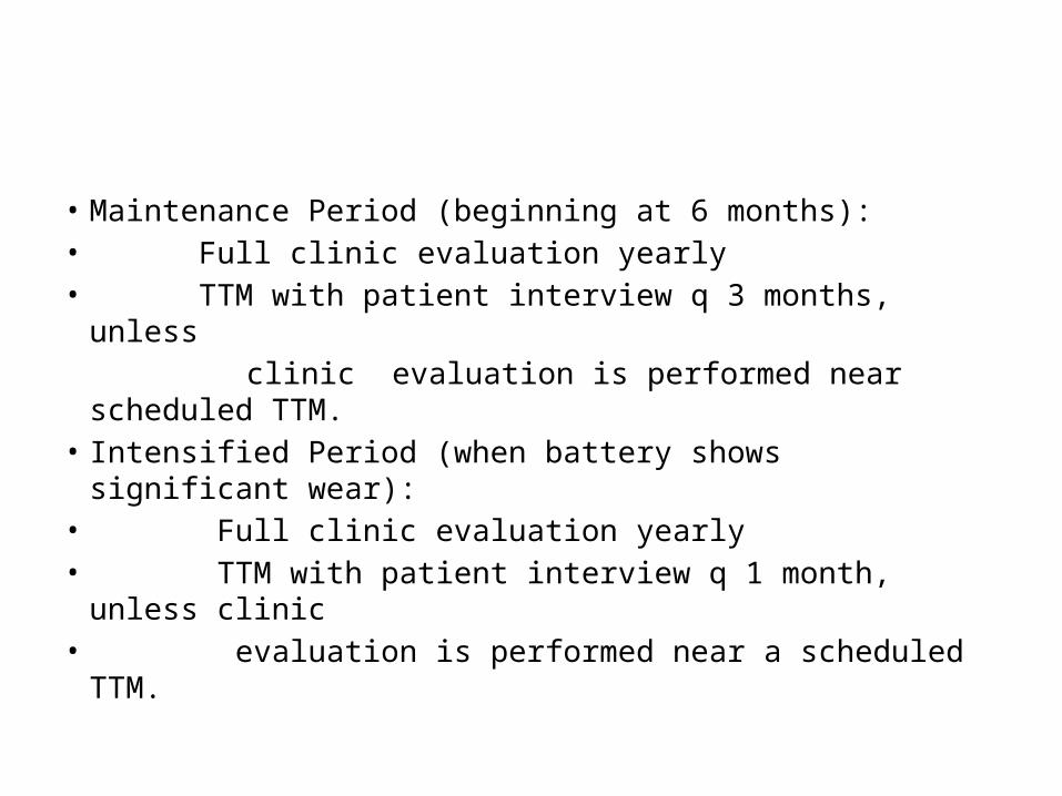
• Maintenance Period (beginning at 6 months):• Full clinic evaluation yearly• TTM with patient interview q 3 months, unless clinic evaluation is performed near scheduled TTM.• Intensified Period (when battery shows significant wear):• Full clinic evaluation yearly• TTM with patient interview q 1 month, unless clinic• evaluation is performed near a scheduled TTM.