Embed Size (px)
Citation preview
Cement Hex Abutment
EB Implant System
Neo CMI Implants Merits In sinus the maxillary posterior area
SCRP® Prosthetics System
EB Implant System Chart
Advantage of CMI Implant
Neo CMI Implants Body structure and Characteristics
Advantages of SCRP® Multi Abutments
All In One Kit Composition
Other Components
Characteristic of Drill
S-Wide Kit Composition
EB Fixture Surgical Guide
Cover Screw
Temporary Abutment
Lab Analog
SCRP Multi Abutment
Cement Angled Abutment
EB Fixture
Healing Abutment
Impression Coping
Prosthetic Flow Chart
UCLA Plastic Abutment
Housing & Retainer
Ball Lab Analog
UCLA Gold Abutment
Ball Abutment
O-Ring & Impression O-Ring
Ball Abutment Driver
Summary of CMI Implant
Surgical System
EB system Component
EB S-Wide Fixture
UCLA CCM Abutment
Advantages of Neo CMI Implants
Neo CMI Implant strengthens the advantages of straight body and
taper body and compensates for typical drawbacks. Thus, drilling and
implanting processes are quick and exact. Furthermore, initial fixation is
excellent.
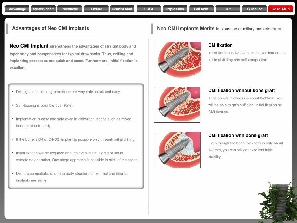
Neo CMI Implants Merits In sinus the maxillary posterior area
• Drilling and implanting processes are very safe, quick and easy.
• Self-tapping is possible(over 95%).
• Implantation is easy and safe even in difficult situations such as mixed
bone(hard-soft-hard).
• If the bone is D4 or D4-D3, implant is possible only through initial drilling.
• Initial fixation will be acquired enough even in sinus graft or sinus
osteotome operation. One stage approach is possible in 90% of the cases
.• Drill are compatible, since the body structure of external and internal
implants are same.
CMI fixation with bone graftEven though the bone thickness is only about
1~3mm, you can still get excellent initial
stability.
CM fixationInitial fixation in D3-D4 bone is excellent due to
minimal drilling and self-compaction.
CMI fixation without bone graftIf the bone's thickness is about 6~11mm, you
will be able to gain sufficient initial fixation by
CMI fixation.
Advantage System chart Prosthetic Fixture Cement Abut. UCLA Impression Ball Abut. Kit Guideline Go to Main
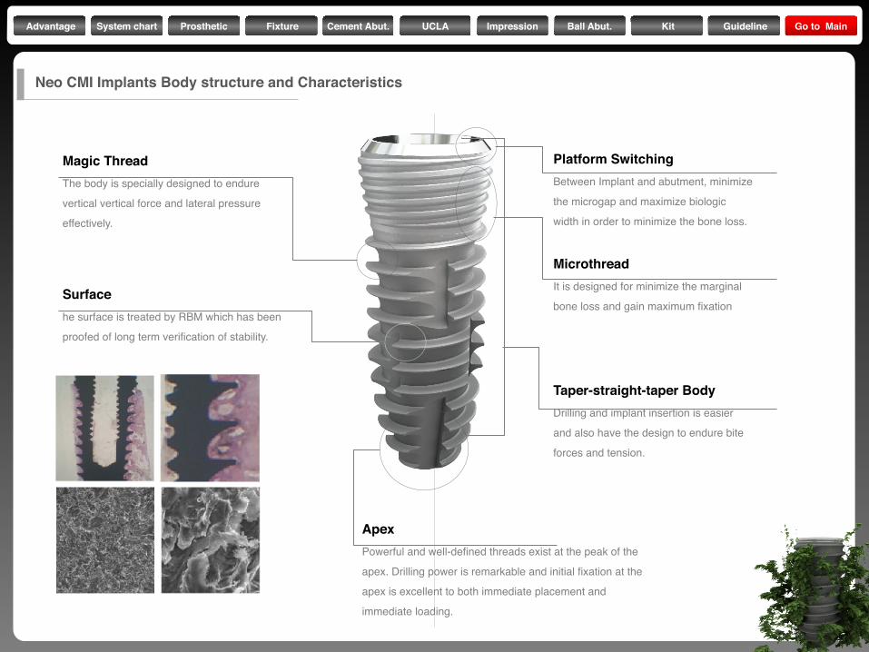
Magic ThreadThe body is specially designed to endure
vertical vertical force and lateral pressure
effectively.
Surfacehe surface is treated by RBM which has been
proofed of long term verification of stability.
ApexPowerful and well-defined threads exist at the peak of the
apex. Drilling power is remarkable and initial fixation at the
apex is excellent to both immediate placement and
immediate loading.
Platform SwitchingBetween Implant and abutment, minimize
the microgap and maximize biologic
width in order to minimize the bone loss.
MicrothreadIt is designed for minimize the marginal
bone loss and gain maximum fixation
Taper-straight-taper BodyDrilling and implant insertion is easier
and also have the design to endure bite
forces and tension.
Neo CMI Implants Body structure and Characteristics
Advantage System chart Prosthetic Fixture Cement Abut. UCLA Impression Ball Abut. Kit Guideline Go to Main
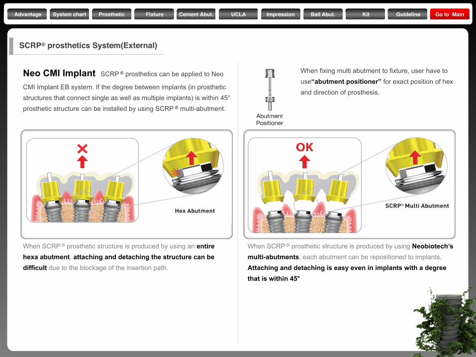
Neo CMI Implant SCRP ® prosthetics can be applied to Neo
CMI Implant EB system. If the degree between implants (in prosthetic structures that connect single as well as multiple implants) is within 45° prosthetic structure can be installed by using SCRP ® multi-abutment.
When SCRP ® prosthetic structure is produced by using an entire hexa abutment, attaching and detaching the structure can be difficult due to the blockage of the insertion path.
When SCRP ® prosthetic structure is produced by using Neobiotech’s multi-abutments, each abutment can be repositioned to implants. Attaching and detaching is easy even in implants with a degree that is within 45°
When fixing multi abutment to fixture, user have to use“abutment positioner” for exact position of hex and direction of prosthesis.
SCRP® prosthetics System(External)
Advantage System chart Prosthetic Fixture Cement Abut. UCLA Impression Ball Abut. Kit Guideline Go to Main
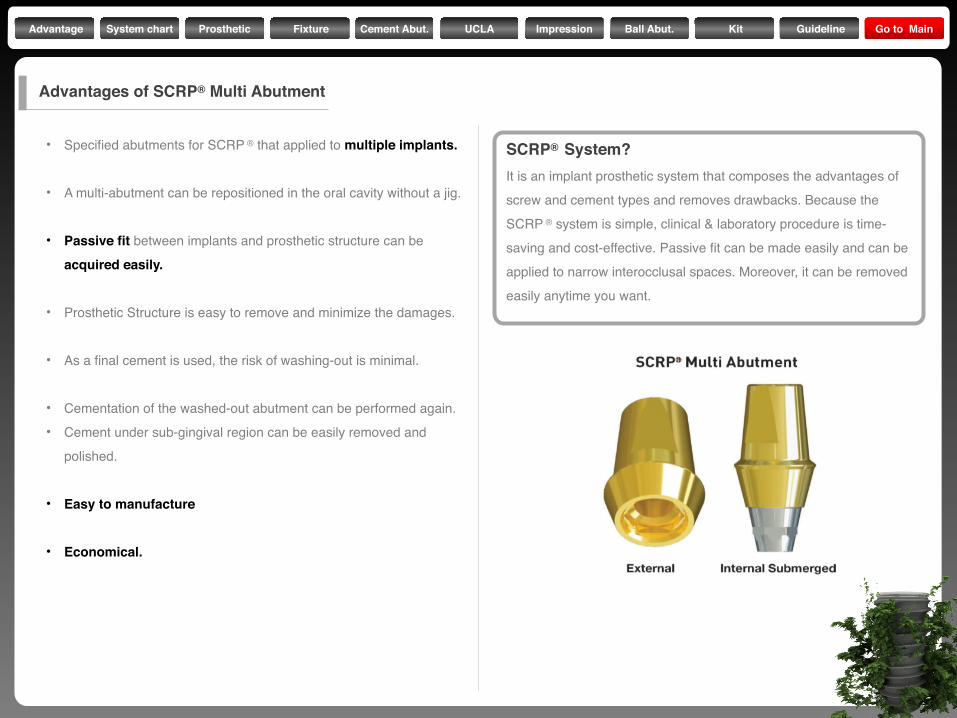
• Specified abutments for SCRP ® that applied to multiple implants.
• A multi-abutment can be repositioned in the oral cavity without a jig.
• Passive fit between implants and prosthetic structure can be
acquired easily.
• Prosthetic Structure is easy to remove and minimize the damages.
• As a final cement is used, the risk of washing-out is minimal.
• Cementation of the washed-out abutment can be performed again.• Cement under sub-gingival region can be easily removed and
polished.
• Easy to manufacture
• Economical.
SCRP® System?It is an implant prosthetic system that composes the advantages of
screw and cement types and removes drawbacks. Because the
SCRP ® system is simple, clinical & laboratory procedure is time-
saving and cost-effective. Passive fit can be made easily and can be
applied to narrow interocclusal spaces. Moreover, it can be removed
easily anytime you want.
Advantages of SCRP® Multi Abutment
Advantage System chart Prosthetic Fixture Cement Abut. UCLA Impression Ball Abut. Kit Guideline Go to Main
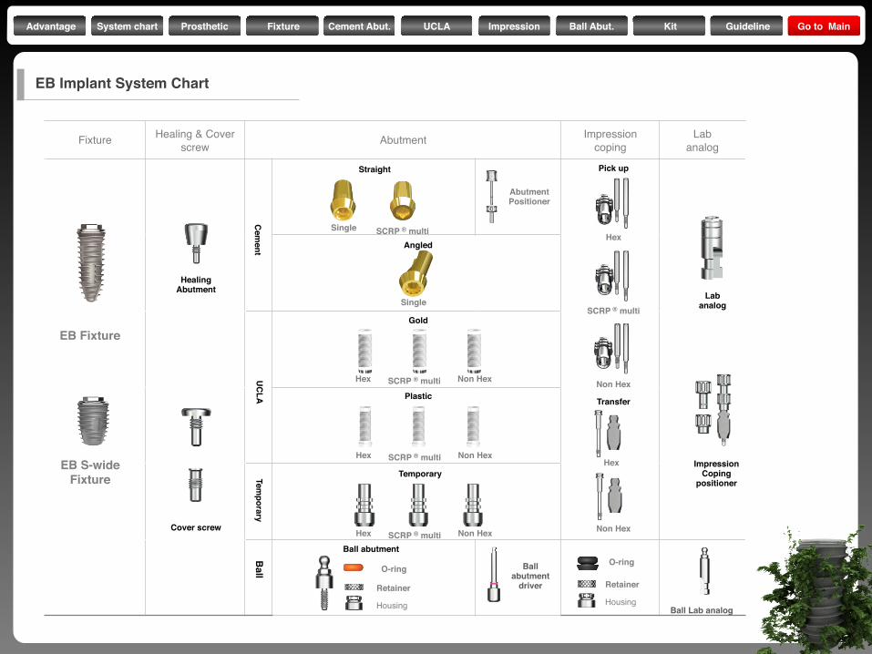
Fixture Healing & Cover screw Abutment Impression
copingLab
analog
Ball abutment
driver
Ball Lab analog
EB Fixture
EB S-wideFixture
Straight
Angled
Gold
Plastic
Temporary
Ball abutment
Pick up
Transfer
Hex
SCRP ® multi
Non Hex
Hex
Non Hex
Hex SCRP ® multi Non Hex
Hex SCRP ® multi Non Hex
Hex SCRP ® multi Non Hex
HealingAbutment
Cover screw
Labanalog
ImpressionCoping
positioner
O-ring
Retainer
Housing
O-ring
Retainer
HousingB
all Tem
poraryU
CLA
Cem
ent
Single SCRP ® multi
Single
AbutmentPositioner
EB Implant System Chart
Advantage System chart Prosthetic Fixture Cement Abut. UCLA Impression Ball Abut. Kit Guideline Go to Main
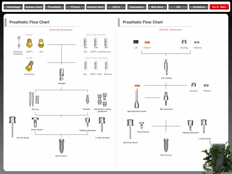
Straight UCLA Gold Abutment
AbutmentPositioner
SCRP ® Hex Hex SCRP ® multi Non-hex
Hex SCRP ® multi Non-hex
Straight
Pick up Transfer Impression copingpositioner
Cover Screw Healing abutment
1.2 Hex driverht0.9 hex driver
Double hex
Angled UCLA Plastic Abutment
Lab Clinical Housing Retainer
Lab analog
Ball abutment driverBall abutment
Cover Screw Healing abutment
1.2 Hex driver
0/0.9 hex driver
Housing Retainer
Prosthetic Flow Chart
External Abutment EB Ball Abutment
Prosthetic Flow Chart
EB Fixture EB Fixture
Advantage System chart Prosthetic Fixture Cement Abut. UCLA Impression Ball Abut. Kit Guideline Go to Main
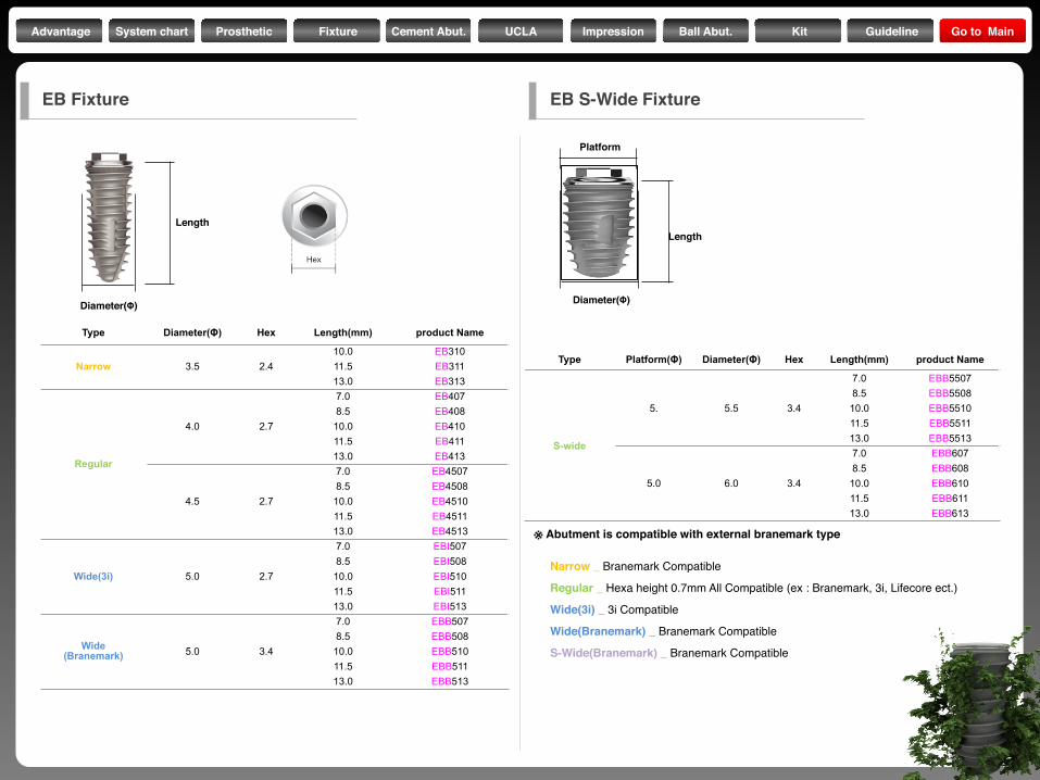
Type Diameter(Φ) Hex Length(mm) product Name
Narrow 3.5 2.410.0 EB31011.5 EB31113.0 EB313
Regular
4.0 2.7
7.0 EB4078.5 EB408
10.0 EB41011.5 EB41113.0 EB413
4.5 2.7
7.0 EB45078.5 EB4508
10.0 EB451011.5 EB451113.0 EB4513
Wide(3i) 5.0 2.7
7.0 EBI5078.5 EBI508
10.0 EBI51011.5 EBI51113.0 EBI513
Wide(Branemark) 5.0 3.4
7.0 EBB5078.5 EBB508
10.0 EBB51011.5 EBB51113.0 EBB513
Diameter(Φ)
Length
Type Platform(Φ) Diameter(Φ) Hex Length(mm) product Name
S-wide
5. 5.5 3.4
7.0 EBB55078.5 EBB5508
10.0 EBB551011.5 EBB551113.0 EBB5513
5.0 6.0 3.4
7.0 EBB6078.5 EBB608
10.0 EBB61011.5 EBB61113.0 EBB613
Diameter(Φ)
Length
Platform
Narrow _ Branemark Compatible
Regular _ Hexa height 0.7mm All Compatible (ex : Branemark, 3i, Lifecore ect.)
Wide(3i) _ 3i Compatible
Wide(Branemark) _ Branemark Compatible
S-Wide(Branemark) _ Branemark Compatible
※ Abutment is compatible with external branemark type
EB Fixture EB S-Wide Fixture
Advantage System chart Prosthetic Fixture Cement Abut. UCLA Impression Ball Abut. Kit Guideline Go to Main
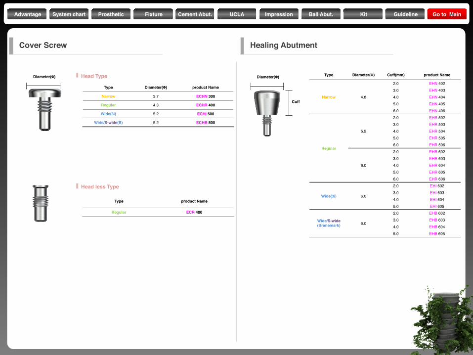
Diameter(Φ)
Type Diameter(Φ) product Name
Narrow 3.7 ECHN 300
Regular 4.3 ECHR 400
Wide(3i) 5.2 ECHI 500
Wide/S-wide(B) 5.2 ECHB 500
Type product Name
Regular ECR 400
Diameter(Φ)
Cuff
Type Diameter(Φ) Cuff(mm) product Name
Narrow 4.8
2.0 EHN 4023.0 EHN 4034.0 EHN 4045.0 EHN 4056.0 EHN 406
Regular
5.5
2.0 EHR 5023.0 EHR 5034.0 EHR 5045.0 EHR 5056.0 EHR 506
6.0
2.0 EHR 6023.0 EHR 6034.0 EHR 6045.0 EHR 6056.0 EHR 606
Wide(3i) 6.0
2.0 EHI 6023.0 EHI 6034.0 EHI 6045.0 EHI 605
Wide/S-wide(Branemark) 6.0
2.0 EHB 6023.0 EHB 6034.0 EHB 6045.0 EHB 605
Cover Screw Healing Abutment
Head Type
Head less Type
Advantage System chart Prosthetic Fixture Cement Abut. UCLA Impression Ball Abut. Kit Guideline Go to Main
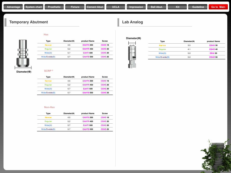
Type Diameter(Φ) product Name Screw
Narrow 4.5 EAHTN 300 CSHS 16
Regular 5.2 EAHTR 400 CSHS 20
Wide(3i) 5.7 EAHTI 500 CSHS 20
Wide/S-wide(B) 5.7 EAHTB 500 CSHS 25
Hex
Type Diameter(Φ) product Name Screw
Narrow 4.5 EAHTN 300 CSHS 16
Regular 5.2 EAHTR 400 CSHS 20
Wide(3i) 5.7 EAHTI 500 CSHS 20
Wide/S-wide(B) 5.7 EAHTB 500 CSHS 25
Type Diameter(Φ) product Name Screw
Narrow 4.5 EAHTN 300 CSHS 16
Regular 5.2 EAHTR 400 CSHS 20
Wide(3i) 5.7 EAHTI 500 CSHS 20
Wide/S-wide(B) 5.7 EAHTB 500 CSHS 25
SCRP ®
Non-Hex
Diameter(Φ)
Type Diameter(Φ) product Name
Narrow 3.5 EBAN 30
Regular 4.1 EBAR 40
Wide(3i) 5.0 EBAI 50
Wide/S-wide(B) 5.0 EBAB 50
Diameter(Φ)
Temporary Abutment Lab Analog
Advantage System chart Prosthetic Fixture Cement Abut. UCLA Impression Ball Abut. Kit Guideline Go to Main
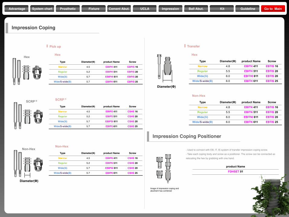
product Name
FDHSET 01
Type Diameter(Φ) product Name Screw
Narrow 4.5 EBIPH 411 EBPIS 16
Regular 5.2 EBIPH 511 EBPIS 20
Wide(3i) 5.7 EBIPHI 611 EBPIS 20
Wide/S-wide(B) 5.7 EBIPH 611 EBPIS 25
Type Diameter(Φ) product Name Screw
Narrow 4.5 EBIPS 411 CSHS 16
Regular 5.2 EBIPS 511 CSHS 20
Wide(3i) 5.7 EBIPSI 611 CSHS 20
Wide/S-wide(B) 5.7 EBIPS 611 CSHS 25
Type Diameter(Φ) product Name Screw
Narrow 4.5 EBIPN 411 CSHS 16
Regular 5.2 EBIPN 511 CSHS 20
Wide(3i) 5.7 EBIPNI 611 CSHS 20
Wide/S-wide(B) 5.7 EBIPN 611 CSHS 25
Diameter(Φ)
Hex
SCRP ®
Non-Hex
Pick up
Hex
SCRP ®
Non-Hex
Impression Coping
Diameter(Φ)
Type Diameter(Φ) product Name Screw
Narrow 4.8 EBITH 411 EBTIS 16
Regular 5.5 EBITH 511 EBTIS 20
Wide(3i) 6.0 EBITHI 611 EBTIS 20
Wide/S-wide(B) 6.0 EBITH 611 EBTIS 25
Type Diameter(Φ) product Name Screw
Narrow 4.8 EBITN 411 EBTIS 16
Regular 5.5 EBITN 511 EBTIS 20
Wide(3i) 6.0 EBITNI 611 EBTIS 20
Wide/S-wide(B) 6.0 EBITN 611 EBTIS 25
Transfer
Hex
Non-Hex
Impression Coping Positioner
Image of impression coping andabutment has combined
- Used to connect with EB, IT, IS system of transfer impression coping screw.- Take each coping body and screw as a positioner. The screw can be connected as relocating the hex by grabbing with one hand.
Advantage System chart Prosthetic Fixture Cement Abut. UCLA Impression Ball Abut. Kit Guideline Go to Main
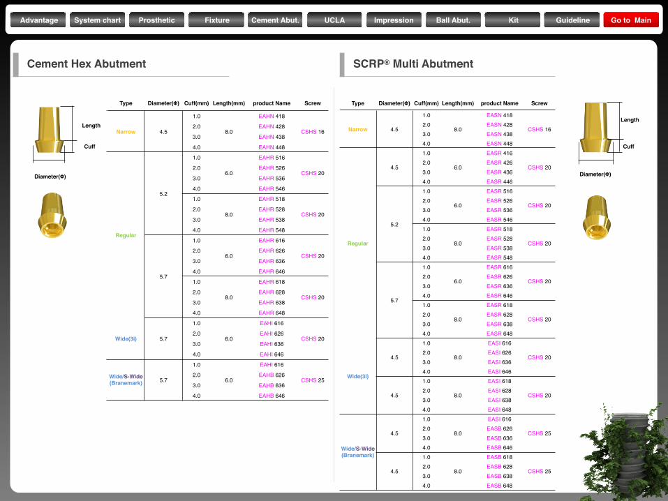
Type Diameter(Φ) Cuff(mm) Length(mm) product Name Screw
Narrow 4.5
1.0
8.0
EASN 418
CSHS 162.0 EASN 4283.0 EASN 4384.0 EASN 448
Regular
4.5
1.0
6.0
EASR 416
CSHS 202.0 EASR 4263.0 EASR 4364.0 EASR 446
5.2
1.0
6.0
EASR 516
CSHS 202.0 EASR 5263.0 EASR 5364.0 EASR 5461.0
8.0
EASR 518
CSHS 202.0 EASR 5283.0 EASR 5384.0 EASR 548
5.7
1.0
6.0
EASR 616
CSHS 202.0 EASR 6263.0 EASR 6364.0 EASR 6461.0
8.0
EASR 618
CSHS 202.0 EASR 6283.0 EASR 6384.0 EASR 648
Wide(3i)
4.5
1.0
8.0
EASI 616
CSHS 202.0 EASI 6263.0 EASI 6364.0 EASI 646
4.5
1.0
8.0
EASI 618
CSHS 202.0 EASI 6283.0 EASI 6384.0 EASI 648
Wide/S-Wide (Branemark)
4.5
1.0
8.0
EASI 616
CSHS 252.0 EASB 6263.0 EASB 6364.0 EASB 646
4.5
1.0
8.0
EASB 618
CSHS 252.0 EASB 6283.0 EASB 6384.0 EASB 648
Diameter(Φ)
Cuff
Length
Cement Hex Abutment SCRP® Multi Abutment
Type Diameter(Φ) Cuff(mm) Length(mm) product Name Screw
Narrow 4.5
1.0
8.0
EAHN 418
CSHS 162.0 EAHN 428
3.0 EAHN 438
4.0 EAHN 448
Regular
5.2
1.0
6.0
EAHR 516
CSHS 202.0 EAHR 526
3.0 EAHR 536
4.0 EAHR 546
1.0
8.0
EAHR 518
CSHS 202.0 EAHR 528
3.0 EAHR 538
4.0 EAHR 548
5.7
1.0
6.0
EAHR 616
CSHS 202.0 EAHR 626
3.0 EAHR 636
4.0 EAHR 646
1.0
8.0
EAHR 618
CSHS 202.0 EAHR 628
3.0 EAHR 638
4.0 EAHR 648
Wide(3i) 5.7
1.0
6.0
EAHI 616
CSHS 202.0 EAHI 626
3.0 EAHI 636
4.0 EAHI 646
Wide/S-Wide (Branemark) 5.7
1.0
6.0
EAHI 616
CSHS 252.0 EAHB 626
3.0 EAHB 636
4.0 EAHB 646
Diameter(Φ)
Cuff
Length
Advantage System chart Prosthetic Fixture Cement Abut. UCLA Impression Ball Abut. Kit Guideline Go to Main
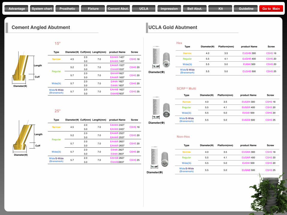
Type Diameter(Φ) Cuff(mm) Length(mm) product Name Screw
Narrow 4.52.0
7.0EAHAN 1427
CSHS 163.0 EAHAN 1437
Regular5.2
2.07.0
EAHAR 1527CSHS 20
3.0 EAHAR1537
5.72.0
7.0EAHAR1627
CSHS 203.0 EAHAR 1637
Wide(3i) 5.72.0
7.0EAHAI 1627
CSHS 203.0 EAHAI 1637
Wide/S-Wide (Branemark) 5.7
2.07.0
EAHAB 1627CSHS 25
3.0 EAHAB1637
15°
Type Diameter(Φ) Cuff(mm) Length(mm) product Name Screw
Narrow 4.52.0
7.0EAHAN 2427
CSHS 163.0 EAHAN 2437
Regular5.2
2.07.0
EAHAR 2527CSHS 20
3.0 EAHAR 2537
5.72.0
7.0EAHAR 2627
CSHS 203.0 EAHAR 2637
Wide(3i) 5.72.0
7.0EAHAI 2627
CSHS 203.0 EAHAI 2637
Wide/S-Wide (Branemark) 5.7
2.07.0
EAHAB 2627CSHS 25
3.0 EAHAB2637
25°
Diameter(Φ)
Cuff
Length
Diameter(Φ)
Cuff
Length
Cement Angled Abutment
Diameter(Φ)
Diameter(Φ)
Diameter(Φ)
Type Diameter(Φ) Platform(mm) product Name Screw
Narrow 4.0 3.5 EUGHN 300 CSHS 16
Regular 5.5 4.1 EUGHR 400 CSHS 20
Wide(3i) 5.5 5.0 EUGHI 500 CSHS 20
Wide/S-Wide (Branemark) 5.5 5.0 EUGHB 500 CSHS 25
Type Diameter(Φ) Platform(mm) product Name Screw
Narrow 4.0 3.5 EUGSN 300 CSHS 16
Regular 5.5 4.1 EUGSR 400 CSHS 20
Wide(3i) 5.5 5.0 EUGSI 500 CSHS 20
Wide/S-Wide (Branemark) 5.5 5.0 EUGSB 500 CSHS 25
Type Diameter(Φ) Platform(mm) product Name Screw
Narrow 4.0 3.5 EUGNN 300 CSHS 16
Regular 5.5 4.1 EUGNR 400 CSHS 20
Wide(3i) 5.5 5.0 EUGNI 500 CSHS 20
Wide/S-Wide (Branemark) 5.5 5.0 EUGNB 500 CSHS 25
Hex
SCRP ® Multi
Non-Hex
UCLA Gold Abutment
Advantage System chart Prosthetic Fixture Cement Abut. UCLA Impression Ball Abut. Kit Guideline Go to Main
Diameter(Φ)
Diameter(Φ)
Diameter(Φ)
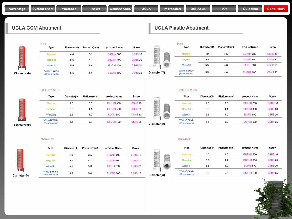
Type Diameter(Φ) Platform(mm) product Name Screw
Narrow 4.0 3.5 EUCHN 300 CSHS 16
Regular 5.5 4.1 EUCHR 400 CSHS 20
Wide(3i) 5.5 5.0 EUCHI 500 CSHS 20
Wide/S-Wide (Branemark) 5.5 5.0 EUCHB 500 CSHS 25
Type Diameter(Φ) Platform(mm) product Name Screw
Narrow 4.0 3.5 EUCSN 300 CSHS 16
Regular 5.5 4.1 EUCSR 400 CSHS 20
Wide(3i) 5.5 5.0 EUCSI 500 CSHS 20
Wide/S-Wide (Branemark) 5.5 5.0 EUCSB 500 CSHS 25
Type Diameter(Φ) Platform(mm) product Name Screw
Narrow 4.0 3.5 EUCNN 300 CSHS 16
Regular 5.5 4.1 EUCNR 400 CSHS 20
Wide(3i) 5.5 5.0 EUCNI 500 CSHS 20
Wide/S-Wide (Branemark) 5.5 5.0 EUCNB 500 CSHS 25
Diameter(Φ)
Diameter(Φ)
Diameter(Φ)
Type Diameter(Φ) Platform(mm) product Name Screw
Narrow 4.0 3.5 EUPHN 300 CSHS 16
Regular 5.5 4.1 EUPHR 400 CSHS 20
Wide(3i) 5.5 5.0 EUPHI 500 CSHS 20
Wide/S-Wide (Branemark) 5.5 5.0 EUPHB 500 CSHS 25
Type Diameter(Φ) Platform(mm) product Name Screw
Narrow 4.0 3.5 EUPSN 300 CSHS 16
Regular 5.5 4.1 EUPSR 400 CSHS 20
Wide(3i) 5.5 5.0 EUPSI 500 CSHS 20
Wide/S-Wide (Branemark) 5.5 5.0 EUPSB 500 CSHS 25
Type Diameter(Φ) Platform(mm) product Name Screw
Narrow 4.0 3.5 EUPNN 300 CSHS 16
Regular 5.5 4.1 EUPNR 400 CSHS 20
Wide(3i) 5.5 5.0 EUPNI 500 CSHS 20
Wide/S-Wide (Branemark) 5.5 5.0 EUPNB 500 CSHS 25
Hex
SCRP ® Multi
Non-Hex
Hex
SCRP ® Multi
Non-Hex
UCLA CCM Abutment UCLA Plastic Abutment
Advantage System chart Prosthetic Fixture Cement Abut. UCLA Impression Ball Abut. Kit Guideline Go to Main
Diameter(Φ)
Cuff
Diameter(Φ)
Length
Diameter(Φ)
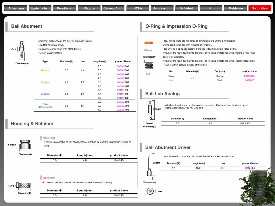
Length
- Abutment that connects the over denture and implant- Use Ball Abutment Driver- Compensate maximum path of 20 degree- Tighten torque: 30Ncm
Type Diameter(Φ) Hex Length(mm) product Name
Narrow 3.5 2.42.0 EABAN 2003.0 EABAN 3004.0 EABAN 400
Regular 4.5 2.72.0 EABAR 2003.0 EABAR 3004.0 EABAR 400
Wide(3i) 5.0 2.72.0 EABAI 2003.0 EABAI 3004.0 EABAI 400
Wide (Branemark) 5.0 3.4
2.0 EABAB 2003.0 EABAB 3004.0 EABAB 400
- Features detachable of Ball Abutment Overdenture by inserting impression O-Ring as final.
Diameter(Φ) Length(mm) product Name
5.0 4.0 BAH 40
- In case of occlusion interval is lower use retainer instead of housing.
Diameter(Φ) Length(mm) product Name
5.0 2.0 BAR 40
Housing
Retainer
Hex Diameter(Φ) Cuff(mm) product Name
Clinical4.5
Orange BAORINGLab Black BAOIMP
- lab, clinical there are two kinds of clinical use and O-ring & ImpressionO-ring can be inserted with Housing or Retainer.- lab O-Ring is specially designed and the following acts are listed below.·Prevents the resin flowing into the under of Housing or Retainer, while making a final resindenture at laboratory.·Prevents the resin flowing into the under of Housing or Retainer, while inserting Housing orRetainer within denture directly at the office.
Lab
Clinical
Diameter(Φ)
Diameter(Φ) Length(mm) product Name
3.5 17.1 BALA 350
- A ball abutment of oral implementation on model of ball abutment (abutment level)- Compatible with EB / IS / S-Mini(ball)
Diameter(Φ) Length(mm) Hex product Name
5.0 25.0 2.4 BADH 24
- A tool used to connect or disconnect the ball abutment to the fixture.
Diameter(Φ)
Length
Diameter(Φ)
Length
Hex
Ball Abutment O-Ring & Impression O-Ring
Ball Abutment Driver
Ball Lab Analog
Housing & Retainer
Advantage System chart Prosthetic Fixture Cement Abut. UCLA Impression Ball Abut. Kit Guideline Go to Main
Surgical System
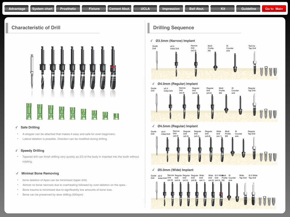
Characteristic of Drill Drilling Sequence
✓ Safe Drilling
✓ Speedy Drilling
✓ Minimal Bone Removing
• A stopper can be attached that makes it easy and safe for even beginners.• Lateral deletion is possible. Direction can be modified during drilling.
• Tapered drill can finish drilling very quickly as 2/3 of the body in inserted into the tooth without rotating.
• bone deletion of Apex can be minimized (taper drill).• Almost no bone necrosis due to overheating followed by over-deletion on the apex..• Bone trauma is minimized due to significantly low amounts of bone loss.• Bone can be preserved by slow drilling.(300rpm)
✓ Ø3.5mm (Narrow) Implant
✓ Ø4.0mm (Regular) Implant
✓ Ø4.5mm (Regular) Implant
✓ Ø5.0mm (Wide) ImplantGuideDrill
NarrowDrill(ø2.9)
RegularDrill(ø3.8)
WideDrill(ø4.1)
RegularDrill(ø3.3)
RegularDrill(ø3.5)
WideDrill(ø4.3)
IS II WideDrill(ø4.5)
ø2.0Initial Drill
MultiProfileEB
IS Countersink
WideTap Drill
IS II WideTap Drill
GuideDrill
NarrowDrill(ø2.9)
RegularDrill(ø3.8)
WideDrill(ø4.1)
RegularDrill(ø3.3)
RegularDrill(ø3.5)
ø2.0Initial Drill
MultiProfileEB
IS Countersink
RegularTap Drill
GuideDrill
NarrowDrill(ø2.9)
RegularDrill(ø3.3)
RegularDrill(ø3.5)
ø2.0Initial Drill
MultiProfileEB
IS Countersink
RegularTap Drill
GuideDrill
NarrowDrill(ø2.9)
ø2.0Initial Drill
MultiProfileEB
IS Countersink
NarrowTap Drill
Advantage System chart Prosthetic Fixture Cement Abut. UCLA Impression Ball Abut. Kit Guideline Go to Main
Drill Extension
Stopper
Surgical Tap Fixture driver
Hex driver ConnectorParallel Pin FixtureDirection Pin
CountersinkGuide DrillInitial DrillTwist surgical Drill
Multi Profile
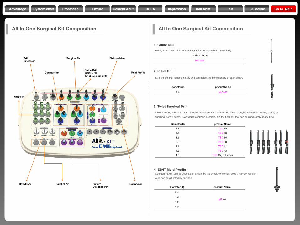
1. Guide Drill
2. Initial Drill
3. Twist Surgical Drill
4. EB/IT Multi Profile
product Name
MICIMP
Diameter(Φ) product Name
2.0 MICIMP
Diameter(Φ) product Name2.9 TSD 29
3.3 TSD 333.5 TSD 353.8 TSD 384.1 TSD 414.3 TSD 434.5 TSD 45(SI II wide)
A drill, which can point the exact place for the implantation effectively.
Straight drill that is used initially and can detect the bone density of each depth.
Laser marking is exists in each size and a stopper can be attached. Even though diameter increases, rooting or sparking merely exists. Exact depth control is possible. It is the final drill that can be used safely at any time.
Countersink drill can be used as an option (by the density of cortical bone). Narrow, regular, wide can be adjusted by one drill.
Diameter(Φ) product Name
3.7
MP 004.3
4.8
5.3
All In One Surgical Kit Composition All In One Surgical Kit Composition
Advantage System chart Prosthetic Fixture Cement Abut. UCLA Impression Ball Abut. Kit Guideline Go to Main
Length(mm) product Name3.0 DS 0304.0 DS 0405.0 DS 0506.0 DS 0607.0 DS 0708.5 DS 085
10.0 DS 10011.5 DS 11513.0 DS 130
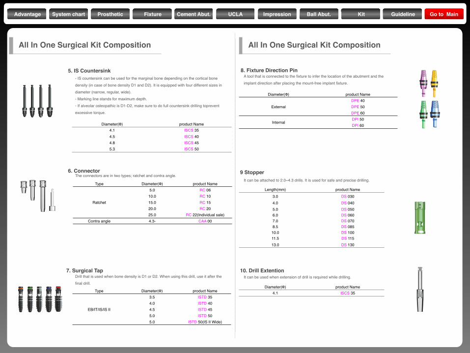
Diameter(Φ) product Name4.1 ISCS 354.5 ISCS 404.8 ISCS 455.3 ISCS 50
5. IS Countersink
6. Connector
7. Surgical Tap
8. Fixture Direction Pin
Type Diameter(Φ) product Name
EB/IT/IS/IS II
3.5 ISTD 354.0 ISTD 404.5 ISTD 455.0 ISTD 505.0 ISTD 50(IS II Wide)
Type Diameter(Φ) product Name
Ratchet
5.0 RC 0610.0 RC 1015.0 RC 1520.0 RC 2025.0 RC 22(Individual sale)
Contra angle 4.3- CAA 00
Diameter(Φ) product Name
ExternalDPE 40DPE 50DPE 60
InternalDPI 50DPI 60
A tool that is connected to the fixture to infer the location of the abutment and the implant direction after placing the mount-free implant fixture.
Drill that is used when bone density is D1 or D2. When using this drill, use it after the final drill.
The connectors are in two types; ratchet and contra angle.
- IS countersink can be used for the marginal bone depending on the cortical bone density (in case of bone density D1 and D2). It is equipped with four different sizes in diameter (narrow, regular, wide).- Marking line stands for maximum depth.- If alveolar osteopathic is D1-D2, make sure to do full countersink drilling toprevent excessive torque.
9 Stopper
10. Drill Extention
Diameter(Φ) product Name4.1 ISCS 35
It can be used when extension of drill is required while drilling.
It can be attached to 2.0~4.3 drills. It is used for safe and precise drilling.
All In One Surgical Kit Composition All In One Surgical Kit Composition
Advantage System chart Prosthetic Fixture Cement Abut. UCLA Impression Ball Abut. Kit Guideline Go to Main
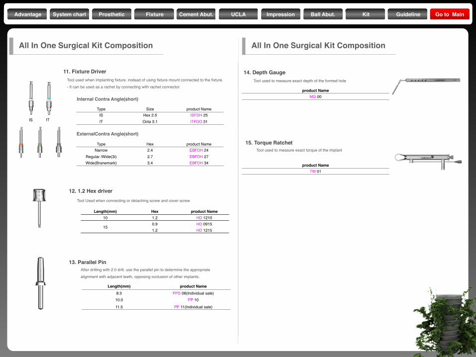
Length(mm) Hex product Name10 1.2 HD 1210
150.9 HD 09151.2 HD 1215
Tool used to measure exact torque of the implant
Tool used to measure exact depth of the formed hole
After drilling with 2.0 drill, use the parallel pin to determine the appropriatealignment with adjacent teeth, opposing occlusion of other implants.
Tool Used when connecting or detaching screw and cover screw
product NameTW 01
product NameMG 00
Length(mm) product Name8.5 PPS 08(Individual sale)
10.0 PP 1011.5 PP 11(Individual sale)
All In One Surgical Kit Composition
12. 1.2 Hex driver
13. Parallel Pin
14. Depth Gauge
15. Torque Ratchet
11. Fixture DriverTool used when implanting fixture, instead of using fixture mount connected to the fixture.- It can be used as a rachet by connecting with rachet connector.
Type Size product NameIS Hex 2.5 ISFDH 25IT Octa 3.1 ITFDO 31
Type Hex product NameNarrow 2.4 EBFDH 24
Regular /Wide(3i) 2.7 EBFDH 27Wide(Branemark) 3.4 EBFDH 34
Internal Contra Angle(short)
ExternalContra Angle(short)
ITIS
All In One Surgical Kit Composition
Advantage System chart Prosthetic Fixture Cement Abut. UCLA Impression Ball Abut. Kit Guideline Go to Main
S-wideStopper
Hex driver
ConnectorMulti Profile
Trephine Drill
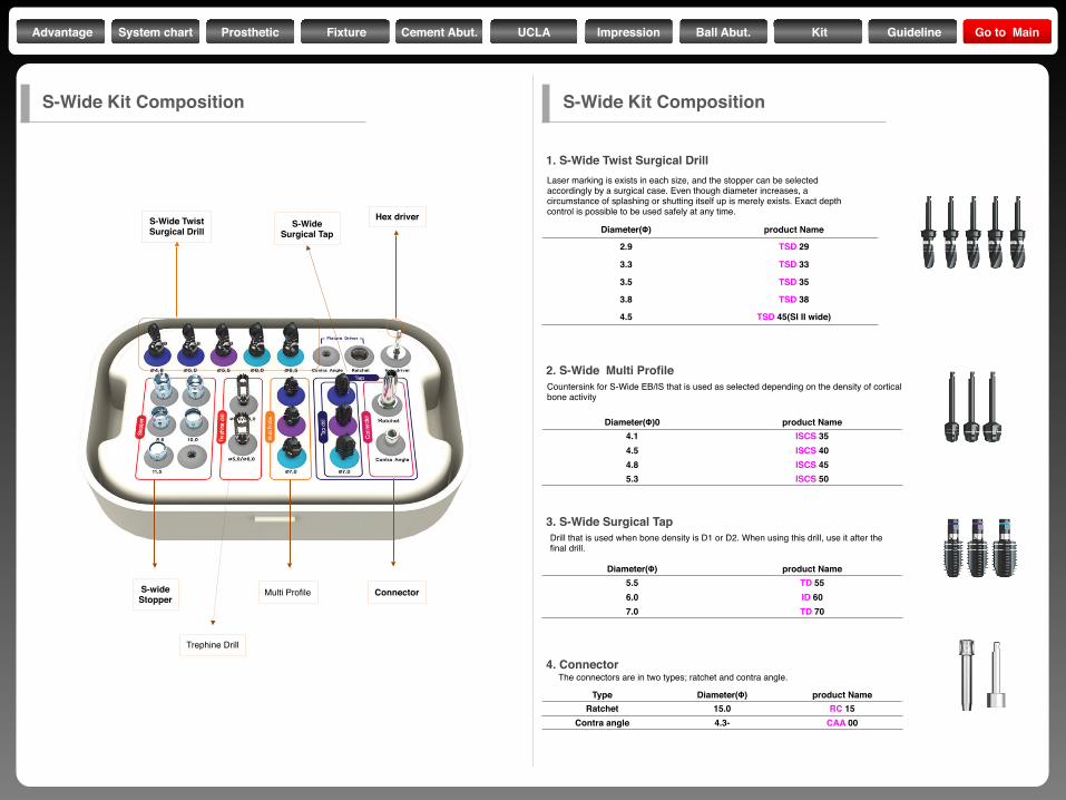
S-Wide TwistSurgical Drill
S-WideSurgical Tap Diameter(Φ) product Name
2.9 TSD 29
3.3 TSD 33
3.5 TSD 35
3.8 TSD 38
4.5 TSD 45(SI II wide)
Laser marking is exists in each size, and the stopper can be selectedaccordingly by a surgical case. Even though diameter increases, acircumstance of splashing or shutting itself up is merely exists. Exact depthcontrol is possible to be used safely at any time.
Countersink for S-Wide EB/IS that is used as selected depending on the density of cortical bone activity
Diameter(Φ)0 product Name4.1 ISCS 354.5 ISCS 404.8 ISCS 455.3 ISCS 50
Diameter(Φ) product Name5.5 TD 556.0 ID 607.0 TD 70
Type Diameter(Φ) product NameRatchet 15.0 RC 15
Contra angle 4.3- CAA 00
Drill that is used when bone density is D1 or D2. When using this drill, use it after the final drill.
The connectors are in two types; ratchet and contra angle.
S-Wide Kit Composition S-Wide Kit Composition
1. S-Wide Twist Surgical Drill
2. S-Wide Multi Profile
3. S-Wide Surgical Tap
4. Connector
Advantage System chart Prosthetic Fixture Cement Abut. UCLA Impression Ball Abut. Kit Guideline Go to Main
Length(mm) product Name6.0 DSL 0607.0 DSL 0708.5 DSL 085
10.0 DSL 10011.5 DSL 115
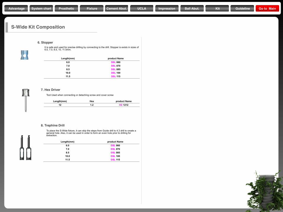
It is safe and used for precise drilling by connecting to the drill. Stopper is exists in sizes of 6.0, 7.0, 8.5, 10, 11.5mm.
Length(mm) Hex product Name12 1.2 HD 1212
Tool Used when connecting or detaching screw and cover screw
Length(mm) product Name6.0 DSL 0607.0 DSL 0708.5 DSL 085
10.0 DSL 10011.5 DSL 115
To place the S-Wide fixture, it can skip the steps from Guide drill to 4.3 drill to create a general hole. Also, it can be used in order to form an even hole prior to drilling for extraction.
7. Hex Driver
8. Trephine Drill
6. Stopper
S-Wide Kit Composition
Advantage System chart Prosthetic Fixture Cement Abut. UCLA Impression Ball Abut. Kit Guideline Go to Main
Type Diameter(Φ) product Name
Narrow 2.9 TSD 29
Regular 3.3 TSD 33
Wide(3i) 3.5 TSD 35
Wide(Branemark) 4.5 TSD 45(SI II wide)
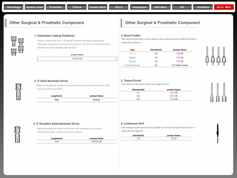
After removing the screw, a tool is used to clean-up the bone around EB fixture before putting the prosthesis..
Tool used to cut the tissue neatly into a shape of circle.
Diameter(Φ)0 product Name4.1 ISCS 354.8 ISCS 455.3 ISCS 50
Diameter(Φ) product Name7.0 TD 70
Side cutting and path correction are possible as a function along with the function of Guide drill and initial drill.
Length(mm) product Name
12.0 ITAD 0L
Length(mm) product Name12.0 ITESDD 00
- Used to connect with EB, IT, IS system of transfer impression coping screw.- Take each coping body and screw as a positioner. The screw can be connected as relocating the hex by grabbing with one hand.
Match the straight line marked on the driver with the groove of solid abutment. After, connect the fixture by rotation.
Match the straight line marked on the driver with the groove of an excellentsolid abutment. After, connect the fixture by rotation.
product Name
FDHSET 01
Other Surgical & Prosthetic Component Other Surgical & Prosthetic Component
1. Impression Coping Positioner
2. IT Solid Abutment Driver
3. IT Excellent Solid Abutment Driver
4. Bone Profiler
5. Tissue Punch
6. Lindemann Drill
Advantage System chart Prosthetic Fixture Cement Abut. UCLA Impression Ball Abut. Kit Guideline Go to Main
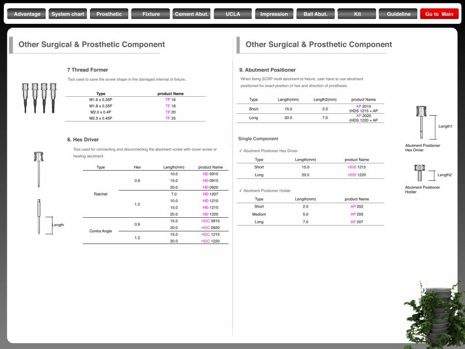
Tool used for connecting and disconnecting the abutment screw with cover screw or healing abutment.
When fixing SCRP multi abutment to fixture, user have to use abutmentpositioned for exact position of hex and direction of prosthesis.
Type Hex Length(mm) product Name
Ratchet
0.910.0 HD 091015.0 HD 091520.0 HD 0920
1.2
7.0 HD 120710.0 HD 121015.0 HD 121520.0 HD 1220
Contra Angle0.9
15.0 HDC 091520.0 HDC 0920
1.215.0 HDC 121520.0 HDC 1220
Type Length(mm) Length2(mm) product Name
Short 15.0 2.0 AP 2015(HDS 1215 + AP
Long 20.0 7.0 AP 2020(HDS 1220 + AP
Type Length(mm) product Name
Short 15.0 HDS 1215
Long 20.0 HDS 1220
Type Length(mm) product Name
Short 2.0 AP 202
Medium 5.0 AP 205
Long 7.0 AP 207
✓ Abutment Positioner Hex Driver
✓ Abutment Positioner Holder
Length1
Length
Length2
Abutment PositionerHex Driver
Abutment PositionerHolder
Other Surgical & Prosthetic Component
8. Hex Driver
9. Abutment Positioner
Single Component
Other Surgical & Prosthetic Component
Type product NameM1.6 x 0.35P TF 16M1.8 x 0.35P TF 18M2.0 x 0.4P TF 20
M2.5 x 0.45P TF 25
Tool used to save the screw shape in the damaged internal of fixture..
7 Thread Former
Advantage System chart Prosthetic Fixture Cement Abut. UCLA Impression Ball Abut. Kit Guideline Go to Main
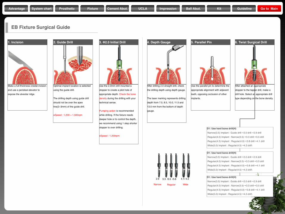
1. Incision
Make a full-thickness crestal incision and use a peristeal elevator to expose the alveolar ridge.
3. Φ2.0 Initial Drill
Use the 2.0mm drill mounted a stopper to create a pilot hole of appropriate depth. Check the bone density during the drilling with your technical sense.
Pumping action is recommended while drilling. If the fixture needs deeper hole or to control the depth, we recommend using 1 step shorter stopper to over drilling.
※Speed : 1,200rpm
4. Depth Gauge
After drilling 2.0 straight drill, check the drilling depth using depth gauge.
The laser marking represents drilling depth from 7.0, 8.5, 10.0, 11.5 and 13.0 mm from the bottom of depth gauge.
5. Parallel Pin
Use the parallel pin to determine the appropriate alignment with adjacent teeth, opposing occlusion of other implants.
6. Twist Surgical Drill
After attached an appropriate stopper to the tapper drill, make a drill hole. Select an appropriate drill type depending on the bone density.
2. Guide Drill
Optimal implant location is selected using the guide drill.
The drilling depth using guide drill should not be over the apex line(2~3mm) of the guide drill.
※Speed : 1,200 ~ 1,500rpm
D1: Use hard bone drill(H)·Narrow(3.5) Implant : Guide drill→2.0 drill→2.9 drill·Regular(4.0) Implant : Narrow(3.5)→3.3 drill→3.5 drill·Regular(4.5) Implant : Regular(4.0)→3.8 drill→4.1 drill·Wide(5.0) Implant : Regular(4.5)→4.3 drill\
D1: Use hard bone drill(H)·Narrow(3.5) Implant : Guide drill→2.0 drill→2.9 drill·Regular(4.0) Implant : Narrow(3.5)→3.3 drill→3.5 drill·Regular(4.5) Implant : Regular(4.0)→3.8 drill→4.1 drill·Wide(5.0) Implant : Regular(4.5)→4.3 drill\
D1: Use hard bone drill(H)·Narrow(3.5) Implant : Guide drill→2.0 drill→2.9 drill·Regular(4.0) Implant : Narrow(3.5)→3.3 drill→3.5 drill·Regular(4.5) Implant : Regular(4.0)→3.8 drill→4.1 drill·Wide(5.0) Implant : Regular(4.5)→4.3 drill\
2.9 3.3 /3.5 /3.8 4.1/ 4.3
Narrow Regular Wide
EB Fixture Surgical Guide
Advantage System chart Prosthetic Fixture Cement Abut. UCLA Impression Ball Abut. Kit Guideline Go to Main
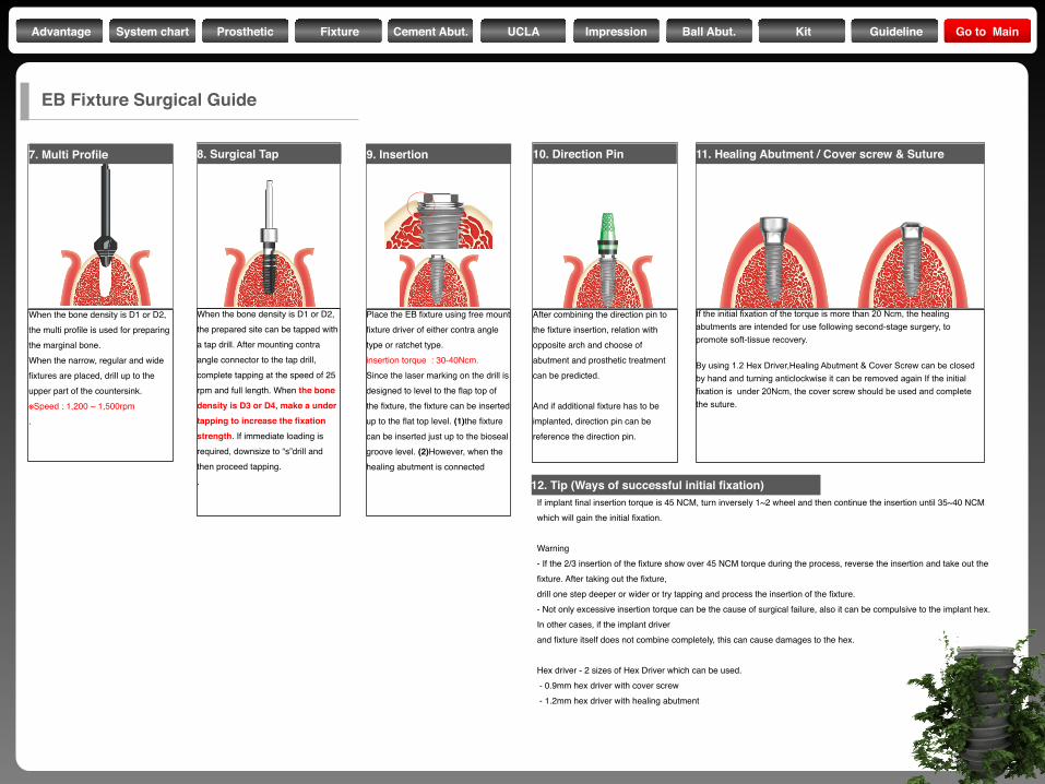
10. Direction Pin
After combining the direction pin to the fixture insertion, relation with opposite arch and choose of abutment and prosthetic treatment can be predicted.
And if additional fixture has to be implanted, direction pin can be reference the direction pin.
11. Healing Abutment / Cover screw & Suture
If the initial fixation of the torque is more than 20 Ncm, the healing abutments are intended for use following second-stage surgery, to promote soft-tissue recovery.
By using 1.2 Hex Driver,Healing Abutment & Cover Screw can be closed by hand and turning anticlockwise it can be removed again If the initial fixation is under 20Ncm, the cover screw should be used and complete the suture.
12. Tip (Ways of successful initial fixation)If implant final insertion torque is 45 NCM, turn inversely 1~2 wheel and then continue the insertion until 35~40 NCM which will gain the initial fixation.
Warning- If the 2/3 insertion of the fixture show over 45 NCM torque during the process, reverse the insertion and take out the fixture. After taking out the fixture,drill one step deeper or wider or try tapping and process the insertion of the fixture.- Not only excessive insertion torque can be the cause of surgical failure, also it can be compulsive to the implant hex. In other cases, if the implant driverand fixture itself does not combine completely, this can cause damages to the hex.
Hex driver - 2 sizes of Hex Driver which can be used. - 0.9mm hex driver with cover screw - 1.2mm hex driver with healing abutment
7. Multi Profile
When the bone density is D1 or D2, the multi profile is used for preparing the marginal bone.When the narrow, regular and wide fixtures are placed, drill up to the upper part of the countersink.※Speed : 1,200 ~ 1,500rpm.
8. Surgical Tap
When the bone density is D1 or D2, the prepared site can be tapped with a tap drill. After mounting contra angle connector to the tap drill,complete tapping at the speed of 25 rpm and full length. When the bone density is D3 or D4, make a under tapping to increase the fixationstrength. If immediate loading is required, downsize to “s”drill and then proceed tapping..
EB Fixture Surgical Guide
9. Insertion
Place the EB fixture using free mount fixture driver of either contra angle type or ratchet type.insertion torque : 30-40Ncm. Since the laser marking on the drill is designed to level to the flap top of the fixture, the fixture can be inserted up to the flat top level. (1)the fixture can be inserted just up to the bioseal groove level. (2)However, when the healing abutment is connected
Advantage System chart Prosthetic Fixture Cement Abut. UCLA Impression Ball Abut. Kit Guideline Go to Main


![How Deep Is Your Love - dreamusic7.web.fc2.com€¦ · Eb AhAAhhAh Eb maj7 Eb 6 Eb maj7 5 AAhhAh Eb Eb maj7 Eb 6 [M2] Fm7/Bb IIII know knowknow your your 9 Eb Gm7 eyesineyes iinninthe](https://img.pdfslide.us/doc/110x75/5f82817213abe7470b0fcd74/how-deep-is-your-love-eb-ahaahhah-eb-maj7-eb-6-eb-maj7-5-aahhah-eb-eb-maj7-eb.jpg)