Embed Size (px)
Citation preview

28 January 201615:45
Standard Specifications for the Construction of Local Fishing Vessels of less than 24 metres in Length Overall
Country........
Fisheries Act................
Regulation ....................
Section .........................
Schedule 8 Construction of a Fibreglass Local Fishing Vessel

28 January 201615:45
ii
Contents
1 Definitions.......................................................................................................... 1
2. General requirements ......................................................................................... 2
2.1 Moulding shop ............................................................................................... 2
2.2 Workers health and safety .............................................................................. 2
2.3 Ambient humidity .......................................................................................... 2
2.4 Workmanship ................................................................................................. 2
2.5 Hull moulding ................................................................................................ 2
2.6 Cored construction ......................................................................................... 3
2.7 Split Moulds ................................................................................................... 3
2.8 Hull removal from mould .............................................................................. 3
2.9 Materials and storage areas ............................................................................ 3
2.10 Fibreglass reinforcing .................................................................................... 3
2.11 Resin .............................................................................................................. 3
2.12 Resin, gel-coat................................................................................................ 4
2.13 Former materials ............................................................................................ 4
3. Scantlings, hull ................................................................................................... 4
3.1 General ........................................................................................................... 4
3.2 Scantling numeral .......................................................................................... 4
3.3 Hull shell ........................................................................................................ 4
3.4 Keel ................................................................................................................ 4
3.5 Stem ............................................................................................................... 4
3.6 Transom ......................................................................................................... 4
3.7 Transom: Outboard motor powered boats ..................................................... 5
3.8 Counter ........................................................................................................... 5
3.9 Frames ............................................................................................................ 5
3.10 Floors ............................................................................................................. 5
3.11 Longitudinal girders ....................................................................................... 5
3.12 Stringers ......................................................................................................... 5
4. Deck structure .................................................................................................... 5
4.1 General ........................................................................................................... 5
4.2 Moulded Fibreglass decks.............................................................................. 5
4.3 Deck framing: wood ...................................................................................... 6
4.4 Deck, plywood ............................................................................................... 6
4.5 Deck, planked ................................................................................................ 6
5. Hatches and Coamings ....................................................................................... 7
5.1 General ........................................................................................................... 7
5.2 Coamings ....................................................................................................... 7
5.3 Hatches ........................................................................................................... 7
6. Watertight bulkheads ......................................................................................... 8
6.1 General ........................................................................................................... 8
6.2 Bulkhead numbers ......................................................................................... 8
6.3 Bulkhead materials......................................................................................... 8
6.4 Bulkhead bonding to hull ............................................................................... 9
6.5 Floatation chambers ....................................................................................... 9
7. Engine beds ........................................................................................................ 9
7.1 General ........................................................................................................... 9
7.2 Wood/Foam based engine beds ..................................................................... 9
28 January 201615:45
iii
7.3 Metal engine beds .......................................................................................... 9
7.4 Outboard engine mounting .......................................................................... 10
7.5 External shaft support brackets .................................................................... 10
8. Bulwarks .......................................................................................................... 10
8.1 General ......................................................................................................... 10
8.2 Bulwark heights ........................................................................................... 10
8.3 Freeing ports ................................................................................................ 10
9. Wheelhouse / deckhouse .................................................................................. 10
9.1 General ......................................................................................................... 10
9.2 Wheelhouses and deckhouses ...................................................................... 11
9.4 Fibreglass ..................................................................................................... 12
10.5 Access .......................................................................................................... 13
10.6 Handrails ...................................................................................................... 13
10.7 Windows ...................................................................................................... 13
11. Accommodation ............................................................................................... 14
11.1 General ......................................................................................................... 14
11.2 Galley arrangements .................................................................................... 14
11.3 Ventilation.................................................................................................... 14
11.4 Protection of the Crew ................................................................................. 14
12 Painting ............................................................................................................ 14
Appendix 1 Tables ............................................................................................... 16
Appendix 2 Figures .............................................................................................. 25
Appendix 3 ........................................................................................................... 33
List of Schedules .................................................................................................. 33

28 January 201615:45
1
1 Definitions 1.1 For the purpose of Schedule 8 the following definitions shall apply:
i. Length Overall (Loa) is the length overall measured in metres / feet in a straight line
on a line parallel to the design waterline taken from the forward part of the stem at top
to that aftermost part of the transom or outrigger).
ii. Breadth (B) is the maximum breadth of the vessel in metres / feet measured to the
outside of the hull shell moulding.
iii. Depth (D) is the depth in metres / feet at the middle of the length from the bottom of the
keel to the top of the shell moulding.
iv. Scantling Numeral for fibreglass fishing vessels is the result of multiplying Loa x B x
D as defined in the definitions above. The measurements for obtaining the Scantling
Numeral for these regulations shall be made in Metres.
v. Equipment Numeral is for selection of anchors and ground tackle, obtained from the
formula: Loa x (B + D).
vi. Fishing vessel inspector or Inspector means a designated member of the staff of a
maritime or fisheries administration regardless of the grade of the person within these
administrations.
vii. Accelerator is an additive to resin(s) that promotes curing of resin, this can be adjusted
for different ambient workshop temperatures.
viii. Pre-accelerated resin is polyester resin with accelerator pre-mixed, only necessitating
addition of catalyst to cure the resin.
ix. Activated resin is resin with the catalyst added.
x. Catalyst added to pre-accelerated resin to induce final curing of resin.
xi. Foam refers to rigid PVC or closed cell polyurethane foams used in boatbuilding.
xii. Former means any material used to form shapes that make up reinforcing members of
the vessel hull, can be of PVC pipe, foam, wood or cardboard etc. which are then
reinforced with matt to scantling requirements.
xiii. Gelling is the curing of activated liquid resin to a jelly-like state, at which point it shall
not be used for further laminating.
xiv. Gel coat means the outermost protective layer of resin, usually coloured to choice,
which is applied to the mould prior to laminating the hull shell.
xv. Glass reinforcement means glass fibres combined to form chopped strand matt (CSM),
woven roving (WR), cloth or any combination of these fabrics used for laminate
reinforcing.
xvi. Hardening time is the time necessary from the initial setting of resin to the time when
the laminate is hard enough to be removed from mould without distortion.
xvii. BARCOL Hardness number is a measure of hardness determined through the use of a
test instrument for plastics and soft alloys manufacture by Barbour-Colman Inc. USA.
Model: GYZJ, 931-1
xviii. Intumescent paint means a resin paint which when applied to laminate affords
resistance to direct flame by forming carbonaceous insulating foam, which protects the
underlying laminate.

28 January 201615:45
2
xix. Kiln dried timber is timber which has been heat treated under controlled conditions to
quickly reduce the moisture content of wood to within acceptable percentages for
boatbuilding applications.
xx. Laminate means alternating layers of reinforcement and resin combined to form a
moulding, usually applied by hand.
xxi. Layup is a general term that refers to the number and type of fibreglass materials used
to make up a specified weight of laminate for a moulding.
xxii. Sandwich construction is a method of construction using two laminate layers enclosing
a core of foam, wood, plastic hex-cell or other materials meeting the Ministers approval.
xxiii. Watertight is an enclosure or area so constructed that water will not enter the
enclosure.
xxiv. Weathertight is an enclosure constructed to provide effective protection against rain
and spray allowing the equipment being protected by the enclosure to function properly.
xxv. Collision bulkhead is a watertight bulkhead up to the working deck in the forepart of
the vessel
2. General requirements
2.1 Moulding shop
The Minister or delegated authority may inspect the premises of a contractor named in Form
7, " Application for Permission to Construction or Import a Fishing Vessel". The permission
may not be granted if the building premises are not
under cover;
constructed in such a manner that rain or other moisture sources can make
contact with mould surfaces or any moulding materials in the shop; and,
not free of dust and contaminants likely to affect the laminate quality.
2.2 Workers health and safety
The premises may also be inspected to ensure that they comply with national regulations for
the protection of workers in industry
2.3 Ambient humidity
Lamination shall not be carried out as and when the relative humidity in the work area
exceeds 80%.
2.4 Workmanship
All workmanship shall be in accordance with the best marine practices
2.5 Hull moulding
Hull moulding shall take place in stages that will allow for adequate heat dissipation from
curing laminates before addition of more laminate layers. Lamination shall proceed at a rate
that allows addition of required laminate layers without the need for grinding to provide a
good secondary bond to the underlying laminates.
If an unscheduled delay in laminating occurs such that a good bond is not possible with the
already cured laminates, the Minister or delegated authority may allow the surface of the

28 January 201615:45
3
existing laminate to be ground if satisfied that this would ensure a proper secondary bond for
subsequently applied laminates.
2.6 Cored construction
Cored construction may be allowed provided that only approved core materials are used and
that the lay-up schedules in Table: 02 are followed. The use of vacuum bag construction
techniques should be considered if cored construction is to be used. Approved core materials
may consist of end grain balsa, closed cell foams or PVC hex-cell material. Cores shall not be
placed in way of Keel or Gunwale (sheer) lay-ups. All edges of core material shall be tapered
to allow joining of outer and inner laminates in a manner that does not produce a stress point
at the transition from cored area to solid fibreglass laminate.
2.7 Split Moulds
When a split mould is used the laminates shall be stepped back progressively from the
centreline of mould by 38mm (1½ “) for each laminate on each half of the mould. Both halves
of mould shall be joined together within 48 hours or within such time that the shell laminates
are not completely cured. A hull laid up in this manner shall have 20% extra laminate applied
to the keel area than that specified in the scantling tables.
2.8 Hull removal from mould
Hulls shall not be removed from moulds until the laminate has cured to sufficient hardness to
prevent distortion of the moulding. Hulls should normally have transverse frames,
longitudinals and main bulkheads in place before hull is removed from mould for final outfit.
If this is not practicable, the hull shell must be placed in a properly braced female cradle that
will maintain the hull shape without distortion during the fitting out phase.
2.9 Materials and storage areas
All materials to be used in construction of a fibreglass vessel shall be stored in a dry and dust
proof environment. The manner of storage to be arranged to maintain low humidity levels
until such time, as the materials are required for preparation and use. The storage area shall be
separate from the main, moulding shop area.
2.10 Fibreglass reinforcing
All fibreglass reinforcing materials shall be of the best marine quality suitable for the
moulding of vessel hulls and reinforcing members. These materials may be in the form of
fabric, chopped strand mat (CSM), woven roving (WR), woven cloth or other combinations
of approved fibreglass reinforcing materials. All bulk fibreglass materials must be stored in a
clean dry location and kept wrapped in shipping plastic covers until ready for use. Any
materials pre-cut for use must be wrapped in plastic and stored in a clean dry location until
required.
2.11 Resin
All moulding resins shall be of the best marine quality polyester resins suitable for moulding
vessel hulls and reinforcing members. Resins shall be mixed in strict accordance with the
manufacturers recommendations and instructions. The catalyst and accelerator quantities
should be sufficient to permit a maximum setting time of one hour. Thickening (Thixotropic
paste) in sufficient quantities only to prevent pooling or drainage of resin before gelling takes
place may be used. Resins shall be stored in proper containers away from direct heat sources.
[Resin stocks should be kept to a minimum consistent with the work in progress to avoid
problems with old or expired date, materials. If large quantities of stored resin are

28 January 201615:45
4
unavoidable, consideration should be given to purchase of non-accelerated resins that can be
stored for longer periods and accelerator added prior to use.]
2.12 Resin, gel-coat
Gel-coat resins shall be of the best marine quality; polyester resins, formulated for gel-coat
use and may be pigmented to the required colour by following the manufacturers
recommendations and specifications. Pigmented gel-coat resins shall not be used for general
moulding purposes. Gel-coat resin shall be stored in proper containers away from heat
sources.
Gel-coat and laminating resins shall reach a final cure with a minimum BARCOL hardness
number of 32.
2.13 Former materials
Former materials used for stiffening shell moulding or large panels may be of rigid foam,
PVC pipe, wood, metal or other materials approved by the Minister or delegated authority.
Where wood is used it must be dried to moisture content of not more than 15% and shall be
treated with a wood preservative compatible with polyester moulding resins.
3. Scantlings, hull
3.1 General
Scantlings for any vessel shall not be less than those derived from to the appropriate Tables or
Rules.
3.2 Scantling numeral
When the scantling numeral obtained in accordance with the formula Loa x B x D lies
between any two consecutive numbers in the tables, the scantlings are to be governed by the
greater of the two. The Minister may allow the lower number to be used provided it is not
less than 15 percent of the number arrived at by calculation.
3.3 Hull shell
The hull shell shall be laid up as per the weights given in the Tables.
3.4 Keel
The keel shall be laid up to the required weight and width as given in the Tables.
3.5 Stem
The stem shall be moulded so that there is a gradual reduction of weight from the keel weight
to the weight required for the sheer. The lay-up shall be in 30mm (1.2”) steps per each
600gramme layer from the forefoot to 100mm (4”) per 600gramme layer at the sheer. When
the hull shell is laid up in two halves (split mould) the weights in way of the joint area shall
be increased by 20% over the weights obtained from the Tables.
3.6 Transom
The transom shall have the same basic lay-up weight as the hull shell, additionally the joining
area in way of hull shell and transom shall be increased in weight by 100% by means of extra
laminates. The laminates shall be overlapped by 38mm (1.5”) per each 600gm weight layer.
The transom shall be further stiffened to the approval of the Minister or delegated authority.
28 January 201615:45
5
3.7 Transom: Outboard motor powered boats
Transom structure on boats powered by outboard engines (O/B) shall be constructed in
accordance with the Scantlings from Table: 11. Boats to be fitted with O/B motors shall have
a well installed to accommodate the motor, the forward bulkhead of which is to be at the same
height as that of a straight line square across the boat from gunwale to gunwale at the location
of bulkhead to be fitted. Wells for O/B motor shall have drainage ports to efficiently free the
well of any water shipped over the transom cut out.
3.8 Counter
The centre line area from the end of keel lay-up and along the counter to the transom shall be
reinforced by extra lay-ups as per keel section weights and widths from Tables.
3.9 Frames
The dimensions, scantlings and spacing of frames shall be obtained from the Tables. The
formers used shall be of “top hat” or rectangular section and matted to the hull shell as
required by Tables or the agreed specifications. Frame spacing shall not be less than the
minimum given in the Tables. Where tops of frames are to have gunwales or beam shelves
through bolted to the hull shell, the cores of frames in that area shall be of an approved (dry)
timber to prevent crushing.
3.10 Floors
Floors moulded over formers shall be fitted on tops of the frames and matted to the frames as
per the lay-up given in the Tables.
3.11 Longitudinal girders
Vessels with a Scantling Numeral of 200 and above shall have a central longitudinal girder
installed that at a minimum coincides with the tops of frame floors. Vessels with Scantling
Numeral of 300 and above shall have extra longitudinal side girders installed in addition to
the centre girder.
3.12 Stringers
Where stringers are fitted, they shall be laid up over cores of foam, PVC pipe, fibreglass or
wood formers. Stringers shall be dimensioned and matted to the hull shell as per scantlings
from the Tables. Spacing shall be in accordance with the Tables.
4. Deck structure
4.1 General
All decks, deck structure and framing shall comply with the Scantling Tables. Standard of
workmanship shall be to the best marine practices and quality.
4.2 Moulded Fibreglass decks
Moulded fibreglass decks may be installed, otherwise details of the deck structure and
reinforcing shall be to the approval of the Minister or delegated authority.
28 January 201615:45
6
4.3 Deck framing: wood
All materials used for deck framing purposes shall be of the best grade for marine use, wood
used shall be of an approved species and dried to 15% moisture content before installation in
the vessel. Wooden deck framing shall be installed in accordance with the following:
a) Beam shelves and gunwale Scantlings shall be in accordance with the Scantlings
from Table: 08. Where through bolts are used to secure the beam shelf or
gunwale the tops of frames shall be plugged internally with wood to prevent
local crushing of the frame laminate.
b) Where shaped plywood beam shelves are used they shall be properly matted to
the hull shell with CSM angles on both upper and lower sides of the shelf in
accordance with the layup schedule in Table: 08.
c) All main and ordinary beams shall be of an approved wood, either solid or
laminated. If laminated, beams are to be glued with marine glues such as
Resorcinol or Epoxy resins. Beams shall be moulded and sided as per Table: 08,
beam spacing shall be in accordance with frame spacing, Table: 03. Beams may
be tapered on the moulded side by 25mm (1”) from centre to ends.
d) Deck beams shall be cambered at a rate of not less than 20mm (3/4”) per metre
of breadth of beam.
e) Half beams shall have the same siding as ordinary beams.
f) Carlings shall be of an approved solid wood or laminated, ends shall be housed
or jointed to main beams and securely fastened. Joints used must be designed to
prevent weakening of main beams. Where the length of a Carling exceeds 2.5m
(8.2ft) the moulded measurement shall be increased by 10% and the Carling
suitably supported by under deck pillar(s).
g) Lodging knees of wood or metal shall be installed at each corner of deck
opening delineated by the Carlings and Main Beams. Steel lodging knees shall
be hot dip galvanised before bolting in place or made from non-ferrous metals of
equivalent strength.
h) Tie Rods shall be installed in Carlings adjacent to half beams where the deck
opening is 2m (6.5ft) in length, when a Carling exceeds 2.4m (8ft) in length tie
rods shall be spaced at 2 times the half beam spacing.
4.4 Deck, plywood
Plywood decking shall be installed in accordance with the Scantling as obtained from Table:
08. Marine grade plywood only shall be used for decking on fishing vessels.
Plywood decks shall be bolted and bonded to a plywood shelf flange that has been bonded to
the hull shell. Alternatively, the plywood deck shall be bonded to the hull shell with an equal
sided flange connection in addition to the deck sheathing lay up schedule.
4.5 Deck, planked
Planked decks shall have scantlings in accordance with Table: 07 and shall be of an approved
timber, quarter sawn and pressure treated with an approved preservative if of softwood
species.
a) Planks shall have a maximum width of 125mm (5”) and shall be snaped or stepped into
the covering boards to avoid feather tapered ends. Suitable under-deck chocking shall

28 January 201615:45
7
be installed between beams under covering board to support deck plank ends and
provide land space for suitable fastenings.
b) Butts shall be a minimum of 1.5m apart with a minimum of three passing strakes,
between butts, on the same beam. Plank butt land area on beams must be a minimum of
1.5 times the siding of deck planking for each plank end, where this cannot be attained
butt straps are to be fitted between beams to provide for proper butt joints and
fastenings.
c) Caulked plank seams shall be filled with a suitable flexible, seam caulking compound
after caulking with cotton or oakum.
5. Hatches and Coamings
5.1 General
Hatches and coamings may be made from fibreglass laminate, wood or metals. Hatches and
coamings shall have all necessary fittings to allow rapid secure weather tight closure. Access
hatches for personnel shall not be less than 600mm x 600mm (24”x 24”) clear opening.
5.2 Coamings
Fibreglass hatch coamings may be incorporated in a fibreglass deck moulding or moulded
separately, where the coaming is a separate unit it shall have a flange of suitable size for
bolting to the Carlings.
Wooden coamings may also be made from an approved wood. All corners shall be securely
jointed with dovetail joints or equivalent arrangements approved by the Minister or delegated
authority.
Heights of hatch coamings measured above the freeboard weather deck shall not be less than
indicated in the following:
Vessel Length Overall Minimum Coaming Height
Below 12m (39ft) Loa 200mm (8”)
12m to below 15m (49ft) 300mm (12”)
15m to below 18m (59ft) 380mm (15”)
18m to below 21m (69ft) 460mm (18”)
21m and above 600mm (24”)
Note: This table assumes that the vessel has freeing ports arranged or installed in bulwarks as
per Section 10.3.
5.3 Hatches
All hatches shall be provided with covers and fitted with clamping devices and gaskets or
other equivalent arrangement sufficient to ensure weathertightness. Those hatches that have to
be opened during fishing operations shall be fitted near to the centreline of the vessel as
practical.
Wooden hatch boards shall have a thickness of at least 4mm for each 100mm of unsupported
span subject to a minimum thickness of 40mm and the span shall not exceed 1.5m (4ft
11inch) the width of the bearing surface of the hatch board ends on coamings shall not be less
than 65mm (2.5”).
Hatch boards shall be clearly and permanently marked in relation to their correct position for
proper closure.

28 January 201615:45
8
Hatch cover materials other than wooden planks shall be capable of withstanding a loading of
one metric tonne per square metre. Where hatch covers are made of steel, the maximum
stress, when subjected to a load of one metric tonne per square metre, multiplied by 4.25 shall
not exceed the minimum ultimate strength of the material. Under these loads, the deflection
shall not exceed 0.0028 times the span.
Covers made of materials other than wood or steel shall be at least of equivalent strength to
those made of mild steel and their construction should be of sufficient stiffness to ensure
weather-tightness under a load of one metric tonne per square metre.
Where the Minister or delegated authority has allowed the use of flush hatches where
necessary for a fishing operation, they shall be capable of being closed weather-tight. The
deck fitting for the hatch cover shall be permanently attached to the deck.
Hinged hatches shall be hinged at the forward side of the coaming and have a means of
positive closure operable from above and below when installed over occupied spaces.
6. Watertight bulkheads
6.1 General
In vessels of 10m (33ft) Loa and over watertight bulkheads shall be installed with scantlings
according to the Tables for thickness and stiffening and in numbers as specified in section 8.2.
Watertight bulkheads that have to be pierced shall have watertight glands and/or watertight
doors installed; doors shall be operable from both sides.
6.2 Number of Bulkheads
Watertight bulkheads shall be installed in decked vessels as per the following schedule:
a. Vessels of 10m (33ft) Loa and under 15m (49ft) Loa shall have one (1) collision and two
(2) engine room bulkheads.
b. Vessels of 15m Loa and over machinery spaces, fish holds and accommodation spaces
below deck shall be subdivided by watertight bulkheads. The forward subdivision shall be
constructed as a collision bulkhead.
c. Bulkheads between engine room and fish hold shall have a suitable approved fire resistant
foam insulating material installed on the bulkhead of not less than 50mm (2”) thick, the
foam shall be sheathed with marine plywood or a combination of other approved fire
resistant materials.
d. In vessels of less than 10m Loa, the number and position of watertight bulkheads shall be
subject to approval of the Minister or delegated authority.
e. Pipes piercing the collision bulkhead should be fitted with suitable valves operable from
above the working deck the valve chest should be secured at the collision bulkhead inside
the forepeak. No door, manhole, ventilation duct or any other opening shall be fitted in
the collision bulkhead below the working deck.
f. In vessels of open type less than 9m (30ft) Loa with no weather deck, watertight
bulkhead(s) and floatation chambers shall be installed to the height of thwarts or as
required by the Minister or delegated authority.
6.3 Bulkhead materials
Watertight bulkheads may be of fibreglass, cored fibreglass, wood planking, plywood or other
approved materials with suitable stiffeners as per Table: 10.

28 January 201615:45
9
6.4 Bulkhead bonding to hull
Plywood and wood bulkheads shall be bonded to hull shell in relation to the thickness of
bulkhead as follows:
Thickness of Bulkhead
(mm)
Weight of laminate in Grams for
each side of bulkhead
Under 12 mm 1800
12mm to 22mm 2400
23mm to 30mm 3000
31mm to 44mm 3600
6.5 Floatation chambers
All fibreglass fishing boats of open construction shall be fitted with sealed buoyancy
chambers of sufficient volume that the vessel when fully flooded with all normal crew,
fishing gear and engine(s) aboard will remain afloat. Sealed buoyancy chambers may be filled
with closed cell foam that is non-water absorbent. Buoyancy may be calculated on the basis of
62.4 lbs. per cubic foot or 999.6 kg per cubic metre (in fresh water).
Where the floatation characteristics of a vessel are not known or cannot be readily verified,
the Minister, or delegated authority may require a test to be conducted at the dockside. Items
of equivalent weight and volume to motors, fishing gear, equipment and crew shall be placed
on board at normal locations of each item. The vessel shall then be gradually flooded and the
floatation characteristics determined or verified. The Minister or delegated authority shall
decide whether the vessel so tested meets the approved standards.
7. Engine beds
7.1 General
Engine beds may be constructed of either Fibreglass, or fibreglass sheathed wood or structural
foam cores or of steel. Engine beds shall be at least two and one half times the length of the
engine and gearbox, this length being measured from the forward holding down bolts to the
face of gearbox to shaft coupling. Where a forward power take off drive(s) is fitted, the length
of the engine bed shall be extended to accommodate the machinery to be driven.
7.2 Wood/Foam based engine beds
Wooden or foam cored engine beds shall be matted to the hull shell and stiffened with side
support brackets and transverse stiffeners. The top of the engine bed shall have a continuous
flat steel plate fitted and matted in place; the plate shall not be less than 6mm (1/4”) in
thickness.
7.3 Metal engine beds
Metal engine beds shall be fabricated to suit the make and power of the engine to be installed.
Metal engine beds shall be secured to the hull by through bolting to longitudinal marine
plywood girders matted to the hull shell and suitably stiffened.
For details of alternate methods of engine bed construction see Figures: 6 and 7.

28 January 201615:45
10
7.4 Outboard engine mounting
Where outboard engines or stern drive units are fitted, they shall be installed on a suitably
reinforced transom in accordance with Table: 11.
7.5 External shaft support brackets
Where the stern configuration of a vessel is such that the propeller shaft extends well beyond
the stern post in order to obtain sufficient clearance for the propeller, it shall be properly
supported by an arrangement of brackets.
Metal pads shall be fitted to the hull and through bolted. The brackets shall be attached to the
metal pads by bolts or by welding and arranged to carry a boss for the propeller shaft bearing.
The metal brackets shall be protected from galvanic action. The Minister or delegated
authority may accept non-metallic brackets and pads provided that the arrangement is of
acceptable strength and design.
Where the external shaft length is such that intermediate bearings would be necessary, the
same rules shall apply as those applied to internal intermediate bearings
8. Bulwarks
8.1 General
Bulwarks shall be fitted to all decked fishing vessels; they may be a continuation of the hull
shell suitably reinforced and stiffened, or a separate structure suitably reinforced and to
approval of the Minister or delegated authority.
8.2 Bulwark heights
Bulwarks when installed shall have minimum recommended heights as follows:
Bulwark heights in relation to vessel Loa in metres
Vessel Length Overall (Loa) Bulwark height
Below 12m (39ft) 610mm (24”)
12m to 17m (39 - 55.8ft) 760mm (30”)
Above 17m (55.8 - +) 915mm (36”)
8.3 Freeing ports
All fishing vessels with bulwarks raised above the working/weather deck shall have adequate
freeing ports in the bulwarks on both sides of the vessel. The area of freeing ports shall not be
less than 3% of the bulwark area enclosing the well deck.
If there are already openings in the bulwarks at deck level, these may be included as part of
the required area for freeing ports.
Any on deck stowage of fishing gear and equipment shall be arranged in such a manner that it
does not interfere with freeing port function.
9. Wheelhouse / deckhouse
9.1 General
Where wheelhouses and deckhouses are installed on a fibreglass fishing vessel, they may be
constructed of fibreglass, wood, or metals. Wheelhouses and deckhouses shall be strongly

28 January 201615:45
11
constructed, stiffened and securely fastened to the vessel structure and Carlings with through
bolts, which shall have heavy washers and nuts on each end unless heads are of coach bolt
configuration. All materials used for construction of wheelhouses and deckhouses shall be of
the best marine quality available.
9.2 Wheelhouses and deckhouses
On fishing vessels with Scantling Numbers of 200 and above the Minister or delegated
authority may require wheelhouses and deckhouses be constructed of a material other than
fibreglass.
9.2.1 Steel
The plating thickness of steel shall not be less than 5mm (0.2”). Stiffener spacing shall not be
less than 500mm (19.6”) on centres. The cross sectional dimensions and type of stiffeners
shall be determined from the following table
Weathertight, non-weathertight and partial shelter Side Stiffeners for Steel Deckhouses.
Depth of Panel
Metres
Depth of Panel
feet
Stiffener Scantling
mm
Stiffener Scantling
inch
1.5 4.9 65 x 5.0 (FB) 2.5 x 0.20 (FB)
2.0 6.56 65 x 6.0 (FB) 2.5 x 0.24 (FB)
2.5 8.20 75 x 6.0 (FB) 2.9 x 0.24 (FB)
3.0 9.84 75 x 10.0 (FB) 2.9 x 0.39 (FB)
3.5
4.0
11.48
13.12
65 x 38 x 6 (A) 2.5 x 1.50 (A)
Note: All stiffeners spaced at minimum of 500mm (19.6”) centre to centre. (FB) = Flat Bar (A) = Angle
9.2.2 Aluminium alloy
The plating thickness of aluminium alloys shall not be less than 6.35mm (0.25”). Stiffener
spacing shall not be less than 500mm (19.6”) centres. The cross sectional dimensions and
types of stiffeners shall be determined from the following table.
Weathertight, non-weathertight and partial shelter Side Stiffeners for Aluminium Alloy
Deckhouses.
Depth of Panel
Metres
Depth of Panel
feet
Scantling
mm
Scantling
inch
1.5 4.9 76.2 x 6.4 (FB) 3 x 0.25 (FB)
2.0
2.5
6.56
8.20
63.5 x 38.1 x 6.4 (A) 2.5 x 1.5 x 0.25 (A)
3.0
3.5
4.0
9.84
11.48
13.12
63.5 x 63.5 x 6.4 (A) 2.5 x 2.5 x 0.25 (A)
Note: All stiffeners spaced at minimum of 500mm (19.6”) centre to centre.
(FB) = Flat Bar (A) = Angle
9.2.3 Wood
Wheelhouse and or deckhouse may be constructed of wood if the Minister or delegated
authority is satisfied that the design and methods of construction will resist severe service
conditions and meets the following minimum specifications:

28 January 201615:45
12
9.2.4 Framing
The deckhouse framing for vessels of 12m in length and under shall not be less than 38mm x
70mm (1 ½” x 2 ¾”). All vertical framing stiffeners shall be installed on 600mm (24”)
centres.
The deckhouse framing for vessels above 12m Loa but less than 24m (78.7ft) Loa shall be
45mm x 89mm (1 ¾” x 3 ½”). All stiffeners for vertical framing shall be installed on 600mm
(24”) centres.
9.2.5 Deckhouse Covering
Plywood or plank shall be properly fastened to the framework with screws and/or stainless
steel ringed nails and marine glue.
The thickness of marine plywood sheathing shall not be less than:
12mm (0.5”) in thickness for vessels 12m (39ft) Loa and under;
16mm (5/8”). for vessels over 12m Loa but less than 18m (59ft) Loa
19mm (3/4”) for vessels over 18m but under 24m (78.7ft)
When planking is used, the thickness shall be increased by 10% otherwise, extra horizontal
cross bracing stiffeners of the same cross section as the vertical stiffeners must be placed in
the framework equidistant between top and bottom and securely fastened in place.
Bolt diameters used in wooden deck structures shall normally not be less than 9mm (3/8”),
bolts spacing should not be more than 600mm (24”) on centres around the sill plate. The
bolts shall pass through the sill plate, Carlings and main beams. All bolts, nuts and washers
are to be of hot dip galvanized steel, stainless steel or bronze.
9.2.6 Vertical tie rods
In addition to the bolts through the sill and Carlings, there shall be an arrangement of vertical
tie rods. The rods shall have end flanges top and bottom for bolting the flanges through the
sill and Carling at deck level and through the top plate of the cabin frame. Either steel strap of
6mm x 25mm (1/4” x 1”) or 25mm x 25mm (1”x 1”) angle may be used with suitable end
flanges for bolts. Alternatively 12mm (1/2”) continuous steel rod threaded at both ends may
be used. The tie rods to be installed on 915mm (36”) centres or as approved by the Minister or
delegated authority.
9.2.7 Fibreglass
A fibreglass wheelhouse and or deckhouse shall be adequately constructed and stiffened to
resist severe service conditions. The deckhouses are to be designed with well-cambered decks
and well radiused corners to build rigidity into the structure. The connection to the hull shall
be efficient and watertight, where:
the deck housing is attached to a deck of fibreglass, the deck is to be flanged to form a
lower coaming and the laminate increased by 15%. The coaming shall not be less than
100mm (4 inches) in vessels of less than 15m in length overall and 150mm (6 inches) in
vessels of 15m in length overall but less than 24m in length overall. Flange bolts may be
of steel of not be less than 9mm diameter ( 3/8” inch) on 200 mm centres (8 inches)
the deck housing is attached to a rolled metal section or wood chock and carling of
traditional wood deck, the laminate forming the flanged base of the deck housing is to be
25% heavier that the weight of deck in fibreglass given in the tables. Flange bolts may be
of galvanized or stainless steel of not less than 12mm diameter (1/2 inch) on 250mm
centres (10 inches).

28 January 201615:45
13
Where a superimposed tier is wider than the supporting tier, and when significant loads are to
be carried on the top of a wheelhouse or deckhouse, the Minister or delegated authority may
require additional strengthening to increase the transverse rigidity of the housing.
The laminate and stiffening shall be suitably increased in way of attachments required for
safety and for fishing operations.
9.2.8 Access
All wheelhouses and deckhouses shall be constructed in a manner that allows unimpeded
movement of personnel to and from the wheelhouse or deckhouse. Access doors must be of
weathertight design and shall be operable from both sides; hinges shall be located on the
forward side of opening for doors installed in deckhouse sides. Doorsill heights above the
deck shall be according to those given for coamings in section 5.2.
Where access to wheelhouse / deckhouse roof area is necessary this shall be provided by
provision of permanently mounted ladder(s) or companionway(s).
9.2.9 Handrails
Sufficient handrails shall be securely installed on the outside of wheelhouse, deckhouse and in
the interior of wheelhouse/deckhouse to the satisfaction of the Minister or delegated authority.
9.2.10 Windows
Toughened safety glass or suitable permanently transparent material of equivalent strength
shall be fitted in all wheelhouse windows exposed to the weather. The means of securing
windows and the width of the bearing surfaces shall be adequate having regard to the window
material used.
Deadlights or a suitable number of storm shutters should be provided where there is no other
method of preventing water from entering the hull through a broken window or sidescuttle.
The Minister or delegated authority may accept sidescuttles and windows without deadlights
in side or aft bulkheads of a deckhouse located, on or above the working deck, if satisfied that
the safety of the vessel will not be adversely affected.
Provision shall be made in the wheelhouse for at least three (3) opening windows for cross
ventilation. Window frames may be of metal or wood with adequate drainage provided. The
area around the cut outs for the window frame shall be reinforced to the satisfaction of the
Minister or delegated authority.
Wheel house window glass:
in vessels over 12m (39ft) Loa glass shall be of the toughened type of not less
than 8mm (0.3”) thickness. If the unsupported area of the glass exceeds
760mm x 600mm (30”x 24”) the thickness shall be increased to 10mm
(0.39”).
in vessels of 12m (39ft) Loa or less toughened glass thickness may be reduced
to 6mm (0.25”) provided that the unsupported area of the glass does not
exceed the equivalent of 440mm x 350mm (18” x.14”).
9.2.11 Deck house windows:
Windows shall not exceed 500mm x 350mm (19”x 14”) and the glass thickness
shall be as for wheelhouse.
A deckhouse a window should not be installed at a height of less than 1.5m above
the deck level.

28 January 201615:45
14
10. Accommodation
10.1 General
When a vessel is intended to be at sea for more than 24 hours an adequate standard of
accommodation for all on board shall be provided. This shall include adequate ventilation,
lighting, fresh water supply, sleeping accommodation for each person on board, galley and
toilet facilities. The sleeping bunks shall be of adequate length and breadth to allow the
incumbent to stretch out in comfort.
As specified in Schedule 4 to these Regulations there shall be at least two easily accessible
means of escape from each accommodation space.
10.2 Galley arrangements
Having regard to the intended service of the vessel, satisfactory cooking appliances and
equipment shall be provided. Where a separate galley is provided it shall be of adequate
dimensions for the purpose and shall have sufficient storage space and satisfactory drainage.
Cooking facilities shall not be installed in areas used for sleeping accommodation.
The installation of cooking appliances shall be in accordance with the provisions of Schedule
4 “Fire protection, fire detection, fire extinguishing and fore fighting equipment”.
10.3 Ventilation
All crew accommodation compartments shall have adequate ventilation provided, either
natural or mechanical. Ventilators shall be designed to prevent ingress of water, and shall be
capable of being closed in case of adverse weather or fire.
10.4 Protection of the Crew
In every decked vessel, sufficient bulwarks, guard rails or guard wires shall be provided at the
exposed parts of the freeboard and superstructure decks and the tops of any deckhouses or
companionways used in the operation of the vessel.
In every decked vessel, adequate guard rails, lifelines, gangways or passages shall be
provided for the passage of the crew between their quarters, machinery spaces and working
spaces. Storm rails shall be fitted on the outside of all deckhouses and casings.
Controls of winches, line and net hauling shall be placed in a manner that the operators have
ample room for their unimpeded operation and that they have a clear view on the working
area. The winches and equipment shall be fitted with safety devices that are designed to
prevent accidents.
11. Painting On fibreglass fishing vessels where wood is extensively used for bulkheads and decks, the
wood shall be painted or resin coated only after all installation is complete. Quality marine
paints shall be used on woodwork and the normal applications will consist of a primer coat
over bare wood and at least 2 topcoats of enamel.
Where epoxy or other resins are used to cover bare wood, the manufacturers instructions are
to be carefully followed regarding application and safety precautions to be observed when
using the product.
When painting fibreglass surfaces for colour or Ultra Violet (UV) protection, the surface must
be properly cleaned to remove oils and wax residues from moulding operations. Good quality,
marine enamels, automotive acrylic enamels or 2 part polyurethane paints may be used to
paint fibreglass.

28 January 201615:45
15

28 January 201615:45
16
Appendix 1 Tables
Table 01
Hull laminate (solid)

28 January 201615:45
17
Table 02
Hull laminate (cored)
Table 03
Transverse framing

28 January 201615:45
18
Table 04
Transverse floors

28 January 201615:45
19
Table 05
Longitudinal Stiffeners
Table 06
Centre and Side Girders
28 January 201615:45
20
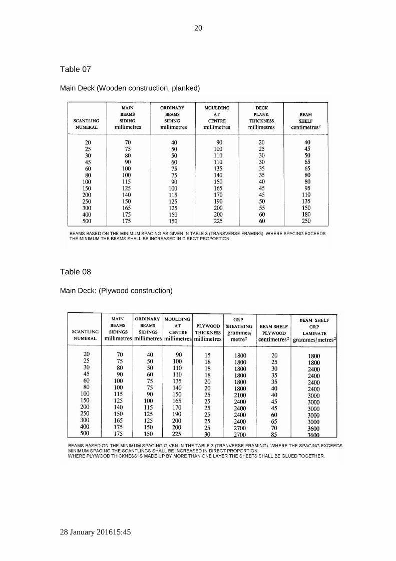
Table 07
Main Deck (Wooden construction, planked)
Table 08
Main Deck: (Plywood construction)

28 January 201615:45
21
Table 09
Watertight Bulkheads (Plywood construction)

28 January 201615:45
22
Table 10
Bulkhead Stiffeners: Vertical

28 January 201615:45
23
Table 11
Transom construction: (O/B Engines)

28 January 201615:45
24
Table 12
Intermediate Shaft Support Bearings
Diameter of Shaft
(mm)
Diameter of Shaft (Inches)
Maximum Shaft Bearing Spacing
Centre to centre in (Metres)
Maximum Shaft Bearing Spacing
Centre to centre in (Feet)
25 0.98 1.21 4.0
30 1.18 1.37 4.5
35 1.38 1.52 5.0
40 1.57 1.66 5.4
45 1.77 1.80 6.0
50 1.97 1.93 6.3
55 2.16 2.05 6.7
65 2.56 2.29 7.5
75 2.95 2.52 8.3
Minimum distance from gearbox coupling flange to the first bearing : = 12 times the shaft diameter e.g., 35mm shaft – distance = 0.42m but Preferable distance = 20 times the shaft diameter e.g., 35mm shaft – distance = 0.70m
See Schedule 10

28 January 201615:45
25
Appendix 2 Figures
Figure 01
Scantling Numeral Dimensions

28 January 201615:45
26
Figure 02
Bulkhead to Hull joint: Reinforced
Figure: 03
Doubled Chine or Transom Reinforcing

28 January 201615:45
27
Figure 04
“V” Bottom Boat Section
n

28 January 201615:45
28
Figure 05
Framing details
Notes: a) Face and Web dimensions shall be in accordance with frame scantling Tables. b) Frame spacing is centre to centre. c) Reinforcing layers of 600gm/m2 as per weights in Transverse Framing Table. d) Angle on web side to suit application. Typically with a Web of 100mm (4inch) the slope is approximately 25mm (1inch) from Face to contact point on hull shell, both sides.

28 January 201615:45
29
Figure 06
Fibreglass (GRP) Engine Bed Arrangement
Figure 07
Alternate Engine Bed Arrangements

28 January 201615:45
30
Figure 08
Split Mould Keel Joint
Figure 09
Keel Reinforcing: One Piece Mould

28 January 201615:45
31
Figure 10
Typical deck beam to beam shelf joint

28 January 201615:45
32
Figure 11
Alternate beam shelf arrangement

28 January 201615:45
33
Appendix 3
List of Schedules
Schedule 1 Prescribed Forms
Schedule 2 Prescribed Fees
Schedule 3 Safety Equipment for a Local Fishing Vessel
Schedule 4 Fire Protection, Fire Detection, Fire Extinguishing and Fire Fighting
Equipment.
Schedule 5 Equipment/Ground Tackle/Anchors and Chains
Schedule 6 Stability and Associated Seaworthiness
Schedule 7 Scantlings for the Construction of a Wooden Hulled Local Fishing Vessel
Schedule 8 Scantlings for the Construction of a Fibreglass Hulled Local Fishing Vessel
Schedule 9 Scantlings for the Construction of a Steel Hulled Local Fishing Vessel
Schedule 10 Machinery and Electrical Installations
Schedule 11 Specifications for the Marking of Fishing Vessels