Embed Size (px)
Citation preview
Some of the challenges implementing an
Arc Flash program
Frank Conte, Senior Electrical Engineer, Insight Engineering Australia
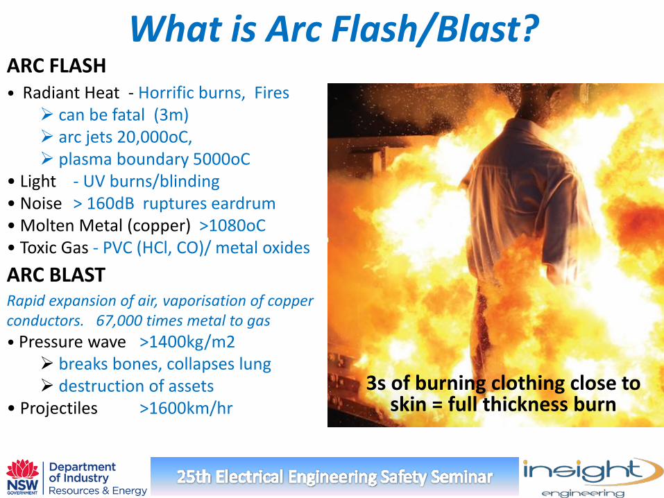
What is Arc Flash/Blast? ARC FLASH • Radiant Heat - Horrific burns, Fires
can be fatal (3m) arc jets 20,000oC, plasma boundary 5000oC
• Light - UV burns/blinding • Noise > 160dB ruptures eardrum • Molten Metal (copper) >1080oC • Toxic Gas - PVC (HCl, CO)/ metal oxides ARC BLAST Rapid expansion of air, vaporisation of copper conductors. 67,000 times metal to gas • Pressure wave >1400kg/m2
breaks bones, collapses lung destruction of assets
• Projectiles >1600km/hr 3s of burning clothing close to
skin = full thickness burn
What is Arc Flash/Blast?
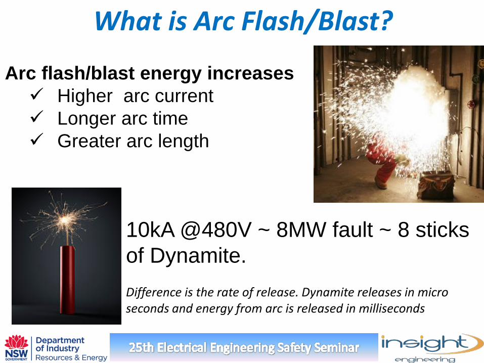
Arc flash/blast energy increases Higher arc current Longer arc time Greater arc length
10kA @480V ~ 8MW fault ~ 8 sticks of Dynamite. Difference is the rate of release. Dynamite releases in micro seconds and energy from arc is released in milliseconds
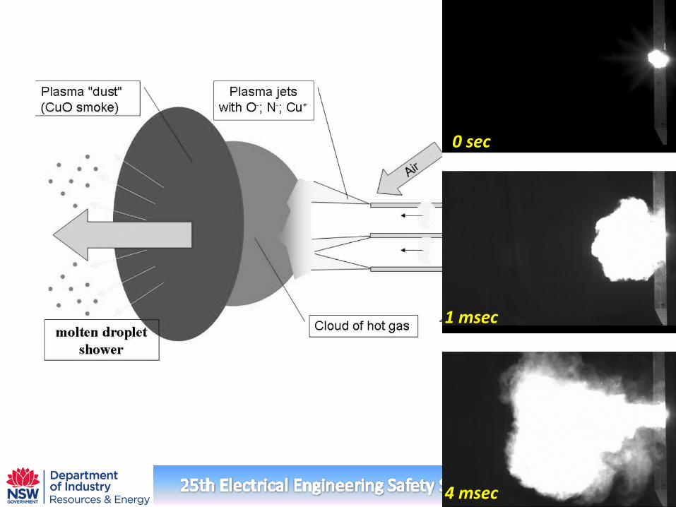
0 sec
1 msec
4 msec
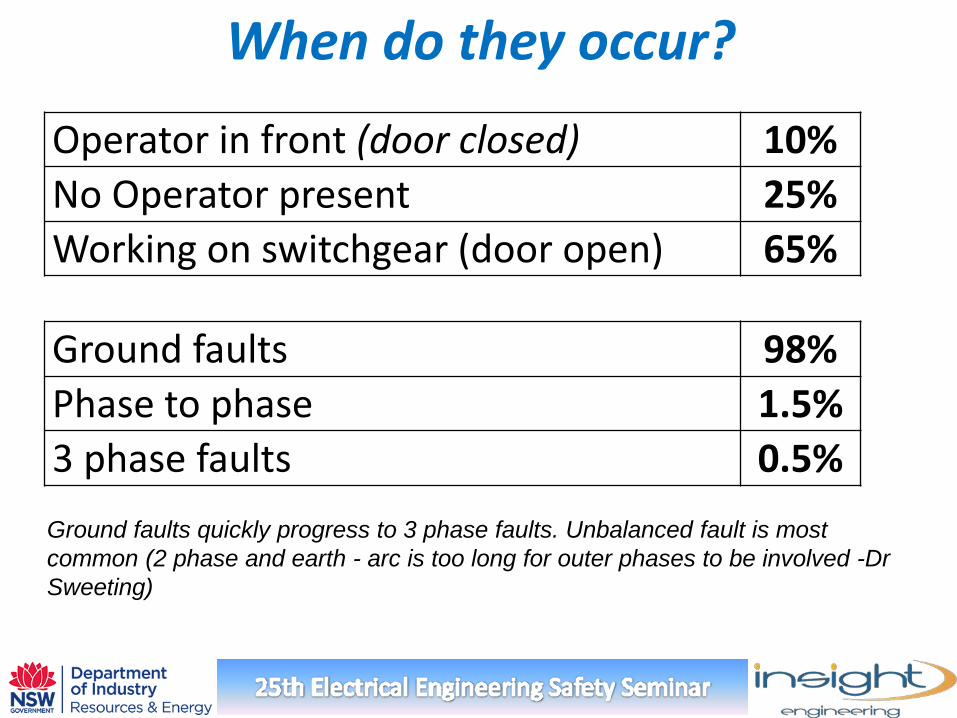
When do they occur?
Ground faults 98% Phase to phase 1.5% 3 phase faults 0.5%
Operator in front (door closed) 10% No Operator present 25% Working on switchgear (door open) 65%
Ground faults quickly progress to 3 phase faults. Unbalanced fault is most common (2 phase and earth - arc is too long for outer phases to be involved -Dr Sweeting)
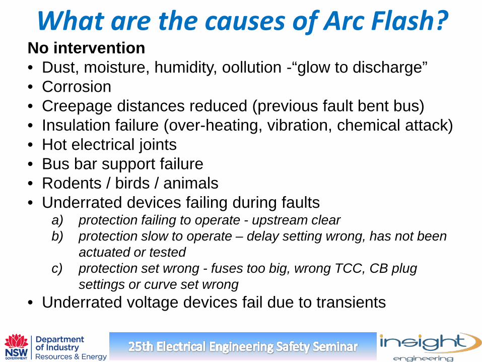
What are the causes of Arc Flash? No intervention • Dust, moisture, humidity, oollution -“glow to discharge” • Corrosion • Creepage distances reduced (previous fault bent bus) • Insulation failure (over-heating, vibration, chemical attack) • Hot electrical joints • Bus bar support failure • Rodents / birds / animals • Underrated devices failing during faults
a) protection failing to operate - upstream clear b) protection slow to operate – delay setting wrong, has not been
actuated or tested c) protection set wrong - fuses too big, wrong TCC, CB plug
settings or curve set wrong • Underrated voltage devices fail due to transients
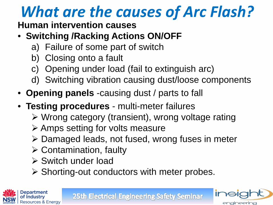
What are the causes of Arc Flash? Human intervention causes • Switching /Racking Actions ON/OFF
a) Failure of some part of switch b) Closing onto a fault c) Opening under load (fail to extinguish arc) d) Switching vibration causing dust/loose components
• Opening panels -causing dust / parts to fall • Testing procedures - multi-meter failures Wrong category (transient), wrong voltage rating Amps setting for volts measure Damaged leads, not fused, wrong fuses in meter Contamination, faulty Switch under load Shorting-out conductors with meter probes.
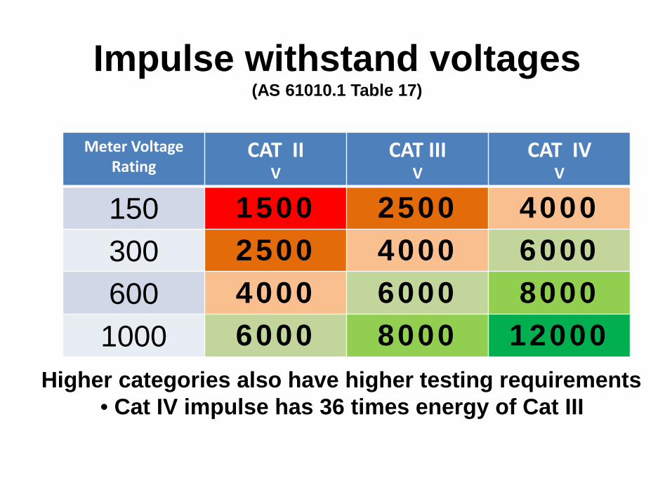
Meter Voltage Rating
CAT II V
CAT III V
CAT IV V
150 1500 2500 4000 300 2500 4000 6000 600 4000 6000 8000
1000 6000 8000 12000
Impulse withstand voltages (AS 61010.1 Table 17)
Higher categories also have higher testing requirements • Cat IV impulse has 36 times energy of Cat III
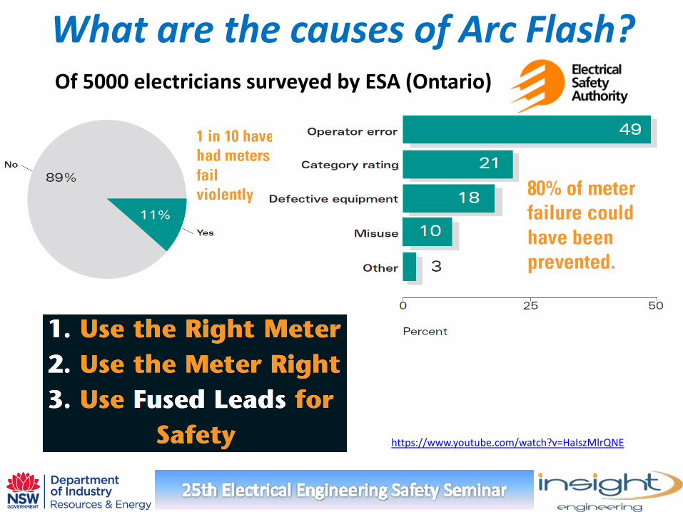
What are the causes of Arc Flash? Of 5000 electricians surveyed by ESA (Ontario)
https://www.youtube.com/watch?v=HaIszMlrQNE
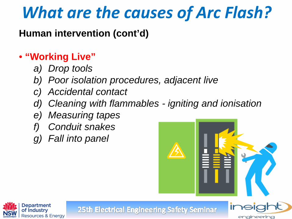
What are the causes of Arc Flash? Human intervention (cont’d) • “Working Live”
a) Drop tools b) Poor isolation procedures, adjacent live c) Accidental contact d) Cleaning with flammables - igniting and ionisation e) Measuring tapes f) Conduit snakes g) Fall into panel
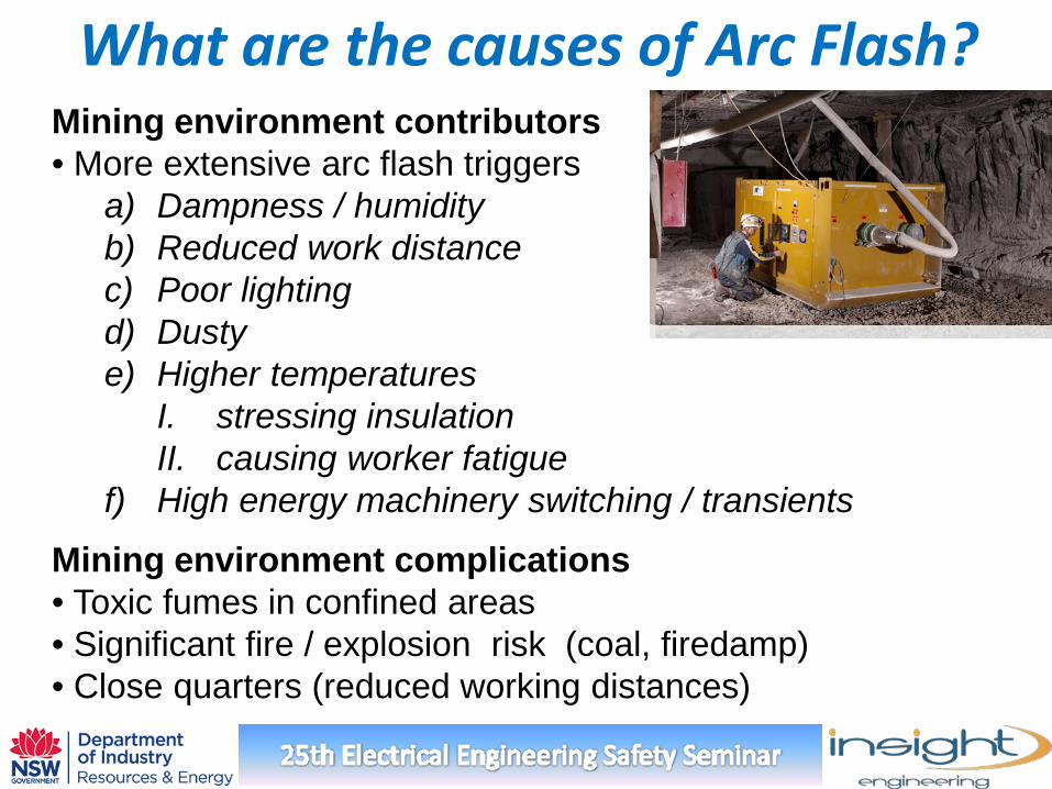
What are the causes of Arc Flash? Mining environment contributors • More extensive arc flash triggers
a) Dampness / humidity b) Reduced work distance c) Poor lighting d) Dusty e) Higher temperatures
I. stressing insulation II. causing worker fatigue
f) High energy machinery switching / transients
Mining environment complications • Toxic fumes in confined areas • Significant fire / explosion risk (coal, firedamp) • Close quarters (reduced working distances)
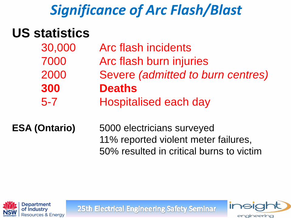
Significance of Arc Flash/Blast US statistics 30,000 Arc flash incidents 7000 Arc flash burn injuries 2000 Severe (admitted to burn centres) 300 Deaths 5-7 Hospitalised each day ESA (Ontario) 5000 electricians surveyed 11% reported violent meter failures, 50% resulted in critical burns to victim
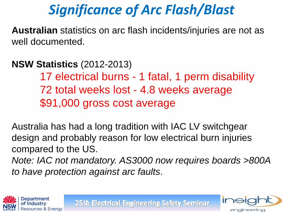
Significance of Arc Flash/Blast Australian statistics on arc flash incidents/injuries are not as well documented. NSW Statistics (2012-2013) 17 electrical burns - 1 fatal, 1 perm disability 72 total weeks lost - 4.8 weeks average $91,000 gross cost average Australia has had a long tradition with IAC LV switchgear design and probably reason for low electrical burn injuries compared to the US. Note: IAC not mandatory. AS3000 now requires boards >800A to have protection against arc faults.
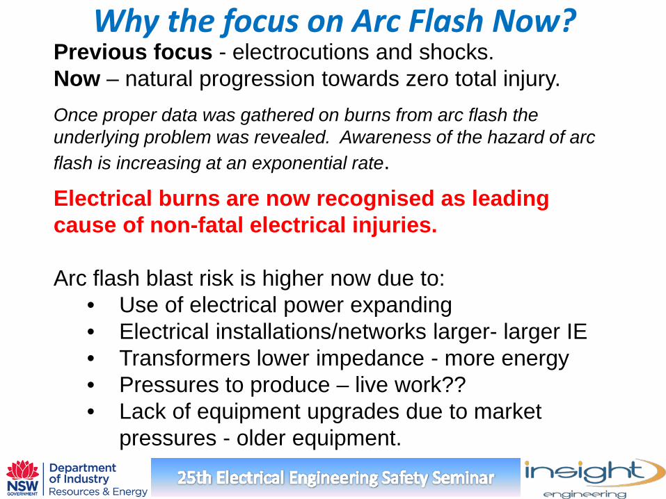
Why the focus on Arc Flash Now? Previous focus - electrocutions and shocks. Now – natural progression towards zero total injury.
Once proper data was gathered on burns from arc flash the underlying problem was revealed. Awareness of the hazard of arc flash is increasing at an exponential rate.
Electrical burns are now recognised as leading cause of non-fatal electrical injuries. Arc flash blast risk is higher now due to:
• Use of electrical power expanding • Electrical installations/networks larger- larger IE • Transformers lower impedance - more energy • Pressures to produce – live work?? • Lack of equipment upgrades due to market
pressures - older equipment.
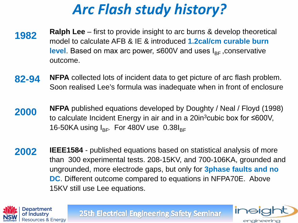
Arc Flash study history? Ralph Lee – first to provide insight to arc burns & develop theoretical model to calculate AFB & IE & introduced 1.2cal/cm curable burn level. Based on max arc power, ≤600V and uses IBF ,conservative outcome.
NFPA collected lots of incident data to get picture of arc flash problem. Soon realised Lee’s formula was inadequate when in front of enclosure
1982
82-94
NFPA published equations developed by Doughty / Neal / Floyd (1998) to calculate Incident Energy in air and in a 20in3cubic box for ≤600V, 16-50KA using IBF. For 480V use 0.38IBF
2000
IEEE1584 - published equations based on statistical analysis of more than 300 experimental tests. 208-15KV, and 700-106KA, grounded and ungrounded, more electrode gaps, but only for 3phase faults and no DC. Different outcome compared to equations in NFPA70E. Above 15KV still use Lee equations.
2002
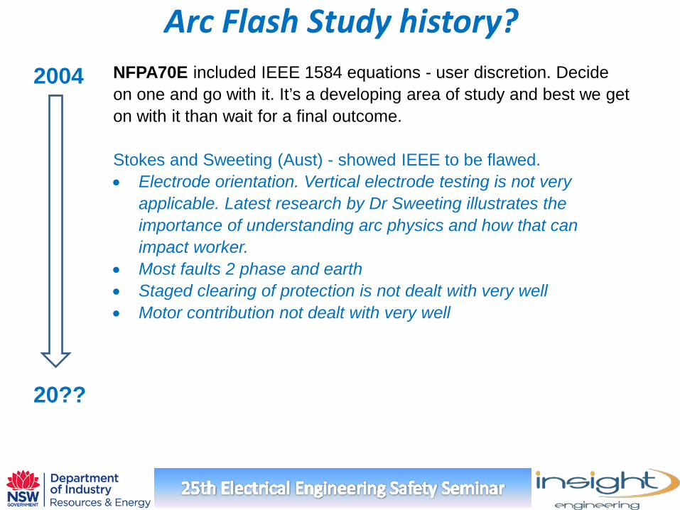
Arc Flash Study history? NFPA70E included IEEE 1584 equations - user discretion. Decide on one and go with it. It’s a developing area of study and best we get on with it than wait for a final outcome. Stokes and Sweeting (Aust) - showed IEEE to be flawed. • Electrode orientation. Vertical electrode testing is not very
applicable. Latest research by Dr Sweeting illustrates the importance of understanding arc physics and how that can impact worker.
• Most faults 2 phase and earth • Staged clearing of protection is not dealt with very well • Motor contribution not dealt with very well
2004
20??
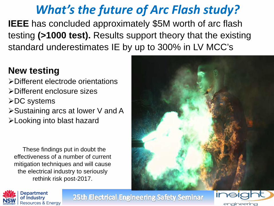
What’s the future of Arc Flash study? IEEE has concluded approximately $5M worth of arc flash testing (>1000 test). Results support theory that the existing standard underestimates IE by up to 300% in LV MCC’s New testing Different electrode orientations Different enclosure sizes DC systems Sustaining arcs at lower V and A Looking into blast hazard
These findings put in doubt the effectiveness of a number of current mitigation techniques and will cause
the electrical industry to seriously rethink risk post-2017.
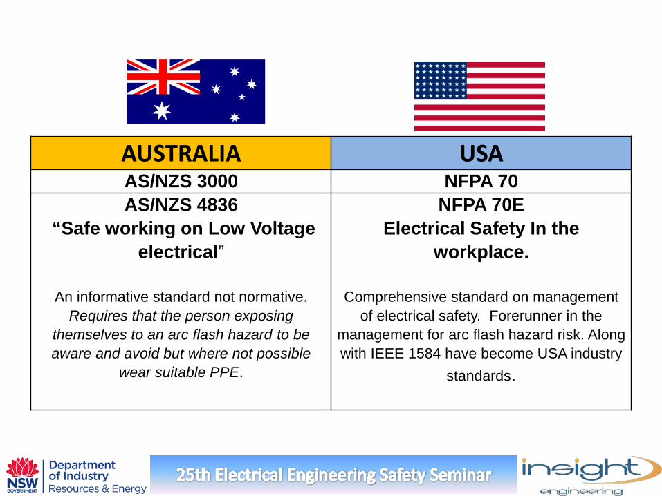
AUSTRALIA USA AS/NZS 3000 NFPA 70 AS/NZS 4836
“Safe working on Low Voltage electrical”
An informative standard not normative.
Requires that the person exposing themselves to an arc flash hazard to be aware and avoid but where not possible
wear suitable PPE.
NFPA 70E Electrical Safety In the
workplace.
Comprehensive standard on management of electrical safety. Forerunner in the
management for arc flash hazard risk. Along with IEEE 1584 have become USA industry
standards.
So what are the directives in Australia? There is no IEC or prescriptive Australian standards dealing with management of arc flash hazard, other than ENA NENS 09. “National guidelines for selecting PPE for Electrical Arc
Hazards”
Local arc flash standards are currently under development.
Regulatory obligation comes directly from WHS Act 2011 requiring management of electrical hazards.
Progressive Australian organisations are using NFPA 70E
and IEEE1584.
Therefore people are generally adopting IEEE 1584 calculation methods and NFPA 70E administration.
What is an Arc Flash Safety Program?
The arc flash/blast hazards and tasks are identified, and the risk is
calculated and prioritised. Immediate and continuing risk
mitigation processes are in place to manage the risk ?
What is involved in an Arc Flash Safety hazard assessment ?
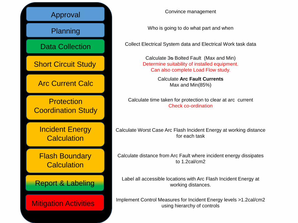
Approval
Data Collection
Short Circuit Study
Arc Current Calc
Protection Coordination Study
Incident Energy Calculation
Report & Labeling
Flash Boundary Calculation
Mitigation Activities
Calculate 3ᴓ Bolted Fault (Max and Min) Determine suitability of installed equipment.
Can also complete Load Flow study.
Calculate Arc Fault Currents Max and Min(85%)
Calculate time taken for protection to clear at arc current Check co-ordination
Calculate Worst Case Arc Flash Incident Energy at working distance for each task
Calculate distance from Arc Fault where incident energy dissipates to 1.2cal/cm2
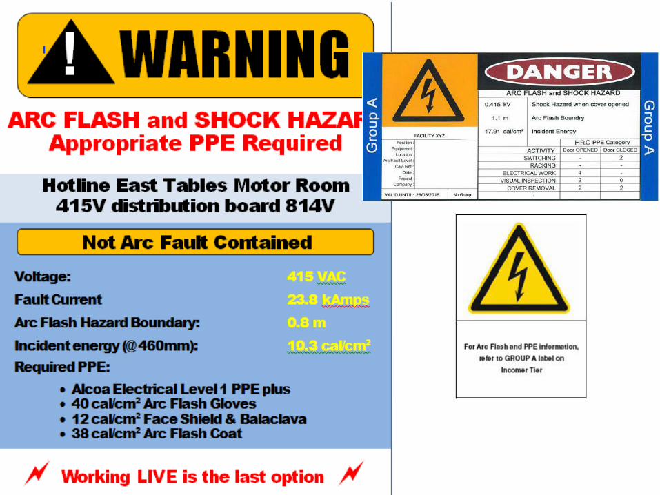
Label all accessible locations with Arc Flash Incident Energy at working distances.
Implement Control Measures for Incident Energy levels >1.2cal/cm2
using hierarchy of controls
Collect Electrical System data and Electrical Work task data
Convince management
Who is going to do what part and when Planning
Challenges
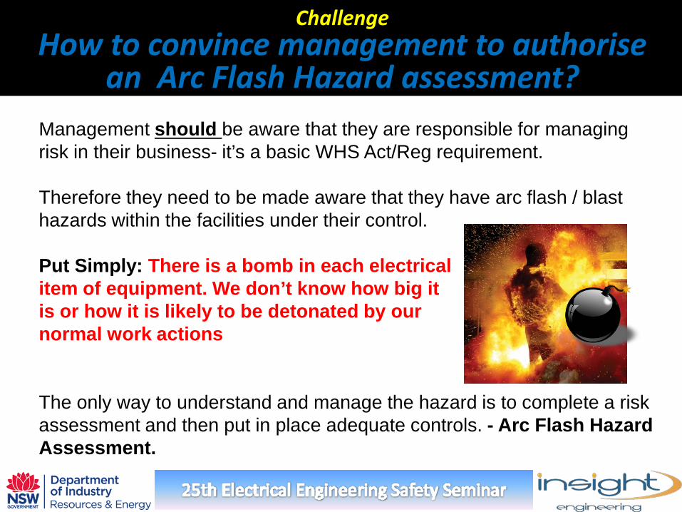
Management should be aware that they are responsible for managing risk in their business- it’s a basic WHS Act/Reg requirement. Therefore they need to be made aware that they have arc flash / blast hazards within the facilities under their control. Put Simply: There is a bomb in each electrical item of equipment. We don’t know how big it is or how it is likely to be detonated by our normal work actions The only way to understand and manage the hazard is to complete a risk assessment and then put in place adequate controls. - Arc Flash Hazard Assessment.
Challenge How to convince management to authorise
an Arc Flash Hazard assessment?
Typical reasons for not doing it We don’t work live!
Still need to interact with electrical switchgear (switching/isolating) Test for dead and fault finding Damage to equipment due to random arc fault is still possible
Lack of Management awareness
Changing management profile. Change from technical-based to financial-based level of management. Engineering risk management lacking or needed.
How to convince management to authorise an Arc Flash Hazard assessment?
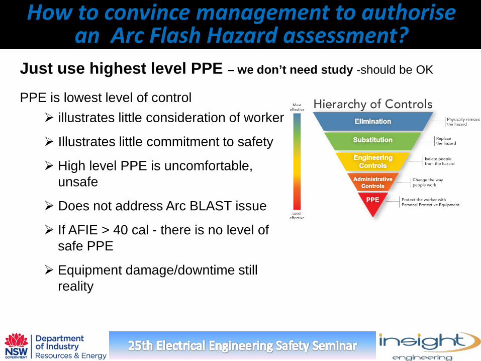
PPE is lowest level of control illustrates little consideration of worker
Illustrates little commitment to safety
High level PPE is uncomfortable, unsafe
Does not address Arc BLAST issue
If AFIE > 40 cal - there is no level of safe PPE
Equipment damage/downtime still reality
How to convince management to authorise an Arc Flash Hazard assessment?
Just use highest level PPE – we don’t need study -should be OK
Category
Indi
vidu
al
Indi
vidu
al
Cond
uctin
g bu
sines
s or
Offi
cer
Body
co
rpor
ate
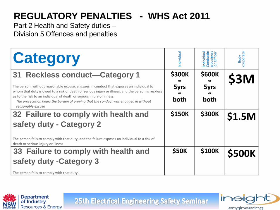
31 Reckless conduct—Category 1 The person, without reasonable excuse, engages in conduct that exposes an individual to whom that duty is owed to a risk of death or serious injury or illness, and the person is reckless as to the risk to an individual of death or serious injury or illness.
The prosecution bears the burden of proving that the conduct was engaged in without reasonable excuse
$300K or
5yrs or
both
$600K or
5yrs or
both
$3M
32 Failure to comply with health and safety duty - Category 2 The person fails to comply with that duty, and the failure exposes an individual to a risk of death or serious injury or illness
$150K $300K $1.5M
33 Failure to comply with health and safety duty -Category 3 The person fails to comply with that duty.
$50K $100K $500K
REGULATORY PENALTIES - WHS Act 2011 Part 2 Health and Safety duties – Division 5 Offences and penalties
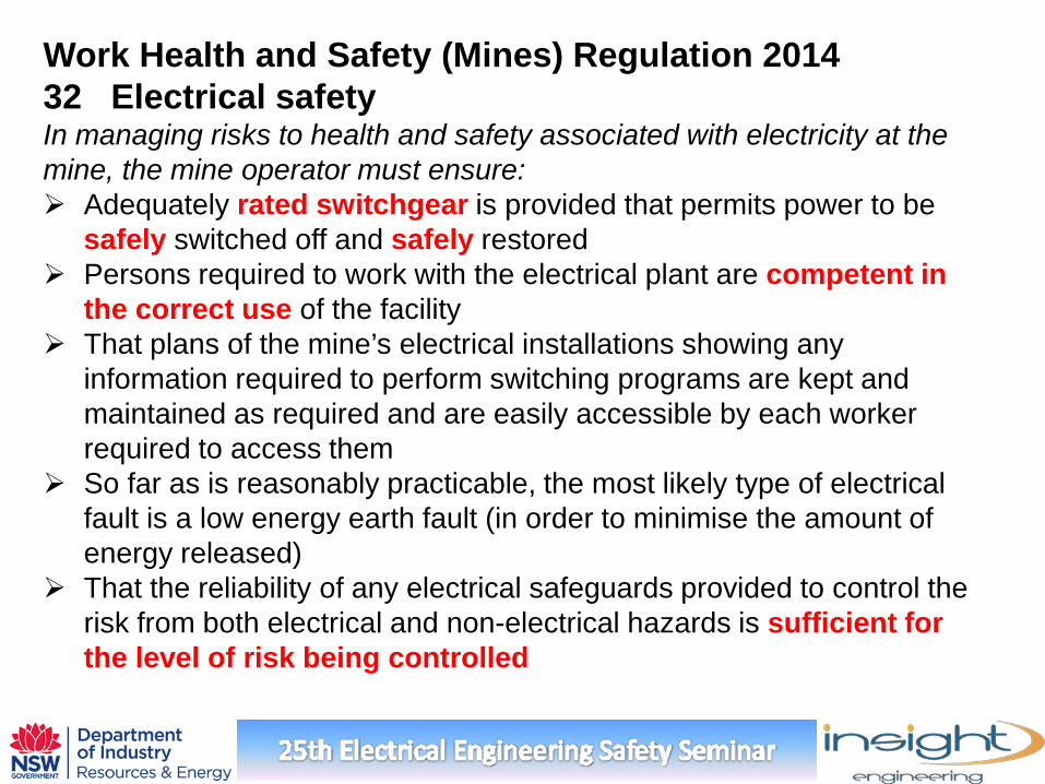
Work Health and Safety (Mines) Regulation 2014 32 Electrical safety In managing risks to health and safety associated with electricity at the mine, the mine operator must ensure: Adequately rated switchgear is provided that permits power to be
safely switched off and safely restored Persons required to work with the electrical plant are competent in
the correct use of the facility That plans of the mine’s electrical installations showing any
information required to perform switching programs are kept and maintained as required and are easily accessible by each worker required to access them
So far as is reasonably practicable, the most likely type of electrical fault is a low energy earth fault (in order to minimise the amount of energy released)
That the reliability of any electrical safeguards provided to control the risk from both electrical and non-electrical hazards is sufficient for the level of risk being controlled
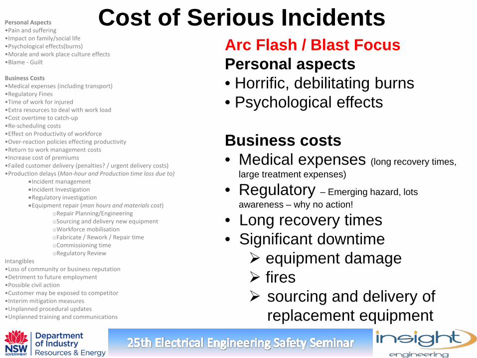
Personal Aspects •Pain and suffering •Impact on family/social life •Psychological effects(burns) •Morale and work place culture effects •Blame - Guilt Business Costs •Medical expenses (including transport) •Regulatory Fines •Time of work for injured •Extra resources to deal with work load •Cost overtime to catch-up •Re-scheduling costs •Effect on Productivity of workforce •Over-reaction policies effecting productivity •Return to work management costs •Increase cost of premiums •Failed customer delivery (penalties? / urgent delivery costs) •Production delays (Man-hour and Production time loss due to)
•Incident management •Incident Investigation •Regulatory investigation •Equipment repair (man hours and materials cost)
oRepair Planning/Engineering oSourcing and delivery new equipment oWorkforce mobilisation oFabricate / Rework / Repair time oCommissioning time oRegulatory Review
Intangibles •Loss of community or business reputation •Detriment to future employment •Possible civil action •Customer may be exposed to competitor •Interim mitigation measures •Unplanned procedural updates •Unplanned training and communications
Arc Flash / Blast Focus Personal aspects • Horrific, debilitating burns • Psychological effects Business costs • Medical expenses (long recovery times,
large treatment expenses)
• Regulatory – Emerging hazard, lots awareness – why no action!
• Long recovery times • Significant downtime equipment damage fires sourcing and delivery of
replacement equipment
Cost of Serious Incidents
Good reasons to do it, advantages of an Arc Flash study
Major electrical system safety and operational health /condition audit. Updated plant electrical system data, single line schematic Update on switchgear documentation and manufacturers
operational updates. Load flow study identifies overloaded equipment. These become
object of IR monitoring, load shedding. Uncover/fix many protection issues. Verify Protective Co-ordination issues Verify equipment Prospective Fault Current withstand Raises the risk profile of certain electrical work activities Helps drive culture for No-Live work priority Knowledge of arc physics provides inherent risk reduction Better understanding of fault propagation and better estimates of
fault level
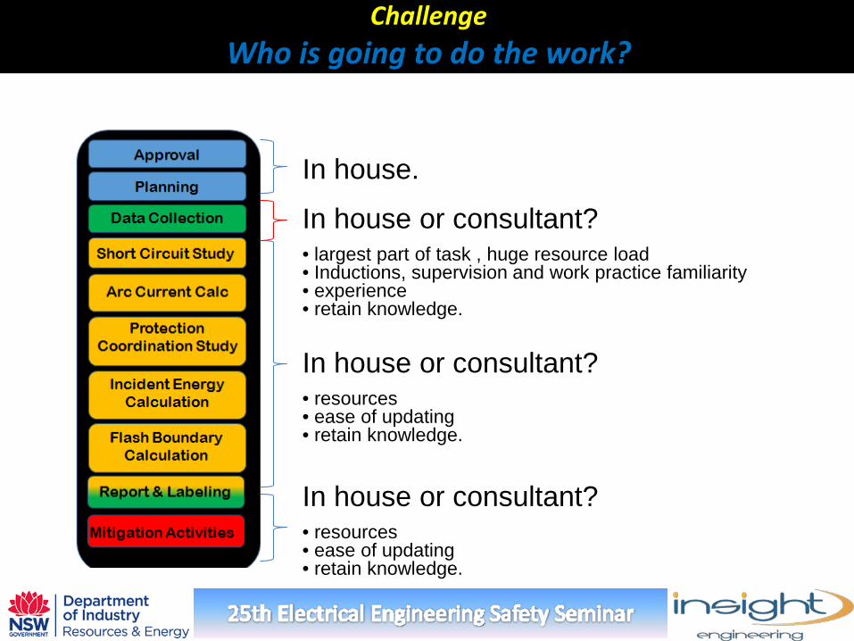
Challenge Who is going to do the work?
In house or consultant? • largest part of task , huge resource load • Inductions, supervision and work practice familiarity • experience • retain knowledge.
In house or consultant? • resources • ease of updating • retain knowledge.
In house or consultant? • resources • ease of updating • retain knowledge.
In house.
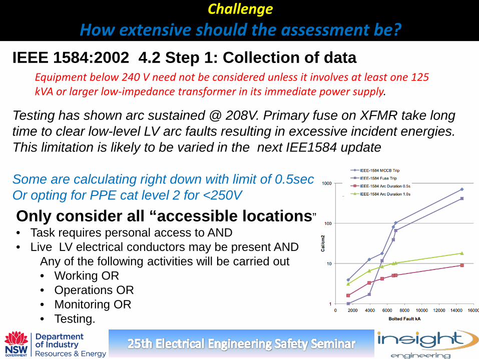
Challenge How extensive should the assessment be?
IEEE 1584:2002 4.2 Step 1: Collection of data Equipment below 240 V need not be considered unless it involves at least one 125 kVA or larger low-impedance transformer in its immediate power supply.
Only consider all “accessible locations” • Task requires personal access to AND • Live LV electrical conductors may be present AND
Any of the following activities will be carried out • Working OR • Operations OR • Monitoring OR • Testing.
Testing has shown arc sustained @ 208V. Primary fuse on XFMR take long time to clear low-level LV arc faults resulting in excessive incident energies. This limitation is likely to be varied in the next IEE1584 update Some are calculating right down with limit of 0.5sec Or opting for PPE cat level 2 for <250V
Challenge The data collection step?
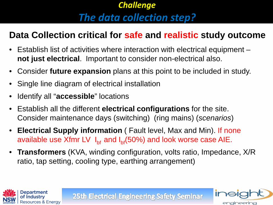
Data Collection critical for safe and realistic study outcome • Establish list of activities where interaction with electrical equipment – not just electrical. Important to consider non-electrical also.
• Consider future expansion plans at this point to be included in study. • Single line diagram of electrical installation • Identify all “accessible” locations • Establish all the different electrical configurations for the site.
Consider maintenance days (switching) (ring mains) (scenarios) • Electrical Supply information ( Fault level, Max and Min). If none
available use Xfmr LV Ibf and Ibf(50%) and look worse case AIE. • Transformers (KVA, winding configuration, volts ratio, Impedance, X/R
ratio, tap setting, cooling type, earthing arrangement)
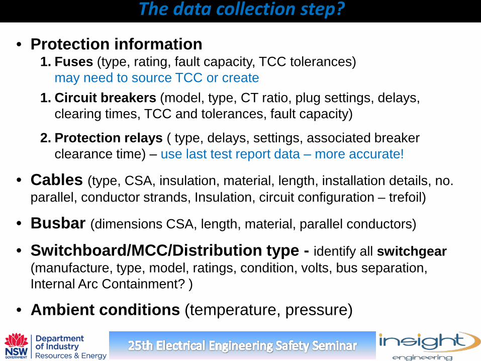
• Protection information 1. Fuses (type, rating, fault capacity, TCC tolerances) may need to source TCC or create 1. Circuit breakers (model, type, CT ratio, plug settings, delays,
clearing times, TCC and tolerances, fault capacity)
2. Protection relays ( type, delays, settings, associated breaker clearance time) – use last test report data – more accurate!
• Cables (type, CSA, insulation, material, length, installation details, no. parallel, conductor strands, Insulation, circuit configuration – trefoil)
• Busbar (dimensions CSA, length, material, parallel conductors)
• Switchboard/MCC/Distribution type - identify all switchgear (manufacture, type, model, ratings, condition, volts, bus separation, Internal Arc Containment? )
• Ambient conditions (temperature, pressure)
The data collection step?
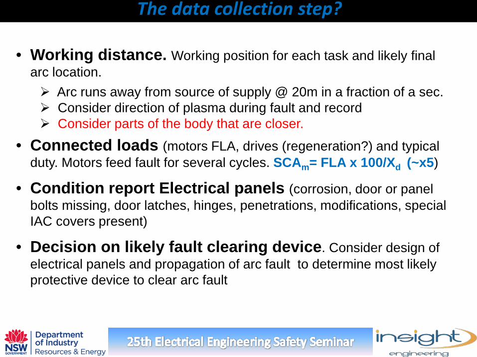
• Working distance. Working position for each task and likely final arc location. Arc runs away from source of supply @ 20m in a fraction of a sec. Consider direction of plasma during fault and record Consider parts of the body that are closer.
• Connected loads (motors FLA, drives (regeneration?) and typical duty. Motors feed fault for several cycles. SCAm= FLA x 100/Xd (~x5)
• Condition report Electrical panels (corrosion, door or panel bolts missing, door latches, hinges, penetrations, modifications, special IAC covers present)
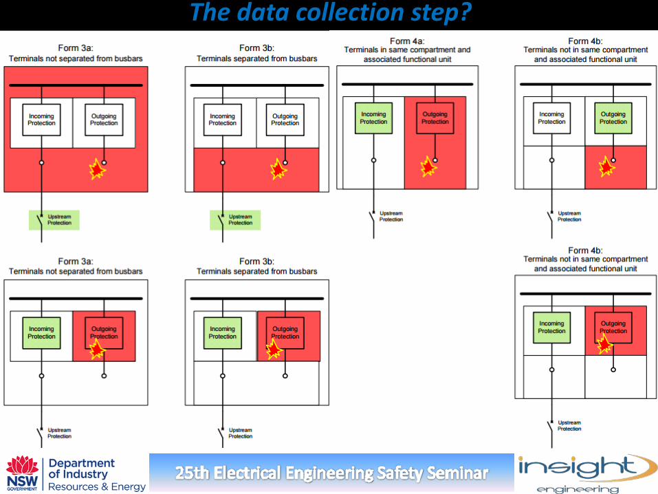
• Decision on likely fault clearing device. Consider design of electrical panels and propagation of arc fault to determine most likely protective device to clear arc fault
The data collection step?
The data collection step?
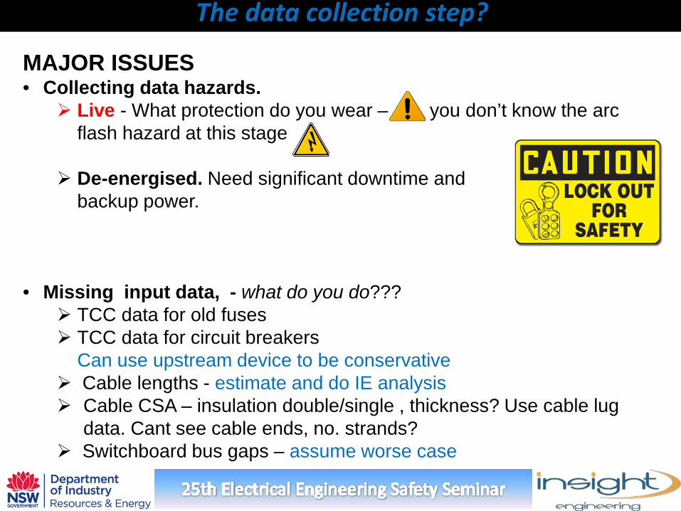
MAJOR ISSUES • Collecting data hazards.
Live - What protection do you wear – you don’t know the arc flash hazard at this stage
De-energised. Need significant downtime and backup power.
• Missing input data, - what do you do??? TCC data for old fuses TCC data for circuit breakers Can use upstream device to be conservative Cable lengths - estimate and do IE analysis Cable CSA – insulation double/single , thickness? Use cable lug
data. Cant see cable ends, no. strands? Switchboard bus gaps – assume worse case
The data collection step?
Challenge Calculation issues?
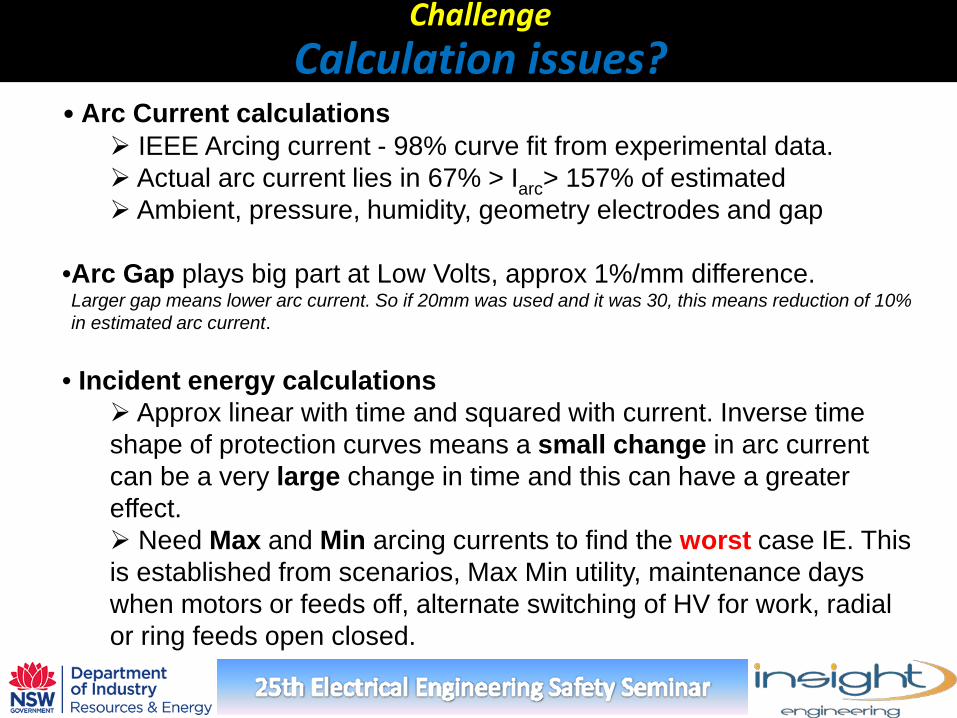
• Arc Current calculations IEEE Arcing current - 98% curve fit from experimental data. Actual arc current lies in 67% > Iarc> 157% of estimated Ambient, pressure, humidity, geometry electrodes and gap
•Arc Gap plays big part at Low Volts, approx 1%/mm difference. Larger gap means lower arc current. So if 20mm was used and it was 30, this means reduction of 10% in estimated arc current.
• Incident energy calculations Approx linear with time and squared with current. Inverse time shape of protection curves means a small change in arc current can be a very large change in time and this can have a greater effect. Need Max and Min arcing currents to find the worst case IE. This is established from scenarios, Max Min utility, maintenance days when motors or feeds off, alternate switching of HV for work, radial or ring feeds open closed.
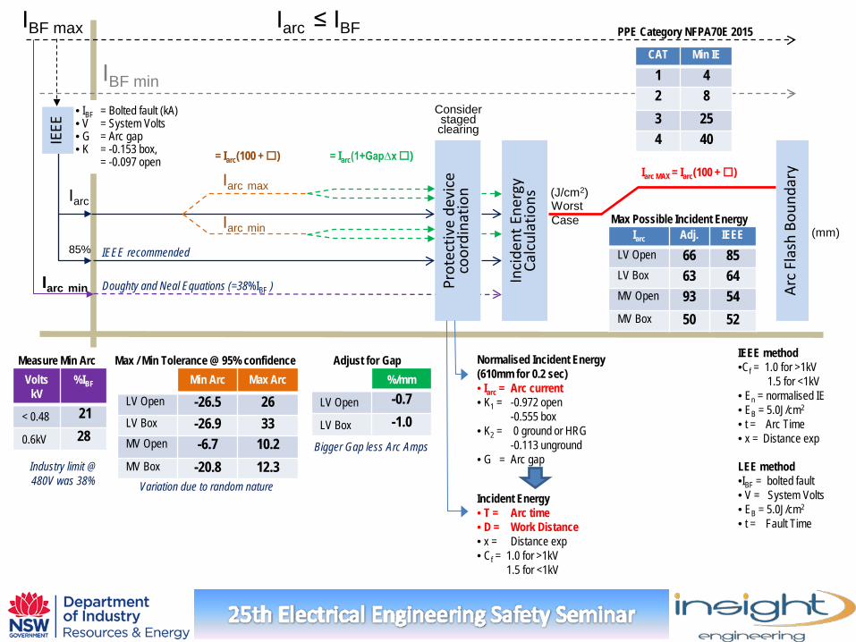
Iarc min
IBF max
Iarc Iarc max
Iarc min
Inci
dent
Ene
rgy
Calc
ulat
ions
Prot
ectiv
e de
vice
co
ordi
natio
n
Worst Case
Arc
Flas
h Bo
unda
ry
(mm)
IEEE method •Cf = 1.0 for >1kV 1.5 for <1kV • En = normalised IE • EB = 5.0J/cm2
• t = Arc Time • x = Distance exp
Iarc Adj. IEEE LV Open 66 85 LV Box 63 64 MV Open 93 54 MV Box 50 52
Min Arc Max Arc
LV Open -26.5 26 LV Box -26.9 33 MV Open -6.7 10.2 MV Box -20.8 12.3
%/mm
LV Open -0.7
LV Box -1.0
Max / Min Tolerance @ 95% confidence Adjust for Gap
Max Possible Incident Energy
Variation due to random nature
Bigger Gap less Arc Amps
= Iarc(1+Gap∆x ) Iarc MAX = Iarc(100 + )
Doughty and Neal Equations (=38%IBF )
85%
Volts kV
%IBF
< 0.48 21
0.6kV 28
IBF min
• IBF = Bolted fault (kA) • V = System Volts • G = Arc gap
• K = -0.153 box, = -0.097 open
Normalised Incident Energy (610mm for 0.2 sec) • Iarc = Arc current • K1 = -0.972 open -0.555 box • K2 = 0 ground or HRG -0.113 unground • G = Arc gap
Incident Energy • T = Arc time • D = Work Distance • x = Distance exp • Cf = 1.0 for >1kV 1.5 for <1kV
= Iarc(100 + )
Measure Min Arc
IEEE
IEEE recommended
LEE method •IBF = bolted fault • V = System Volts • EB = 5.0J/cm2
• t = Fault Time
Iarc ≤ IBF
Industry limit @ 480V was 38%
(J/cm2)
Consider staged clearing
CAT Min IE
1 4 2 8 3 25 4 40
PPE Category NFPA70E 2015
Calculation issues
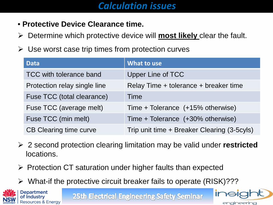
• Protective Device Clearance time. Determine which protective device will most likely clear the fault.
Use worst case trip times from protection curves
2 second protection clearing limitation may be valid under restricted locations.
Protection CT saturation under higher faults than expected
What-if the protective circuit breaker fails to operate (RISK)???
Data What to use
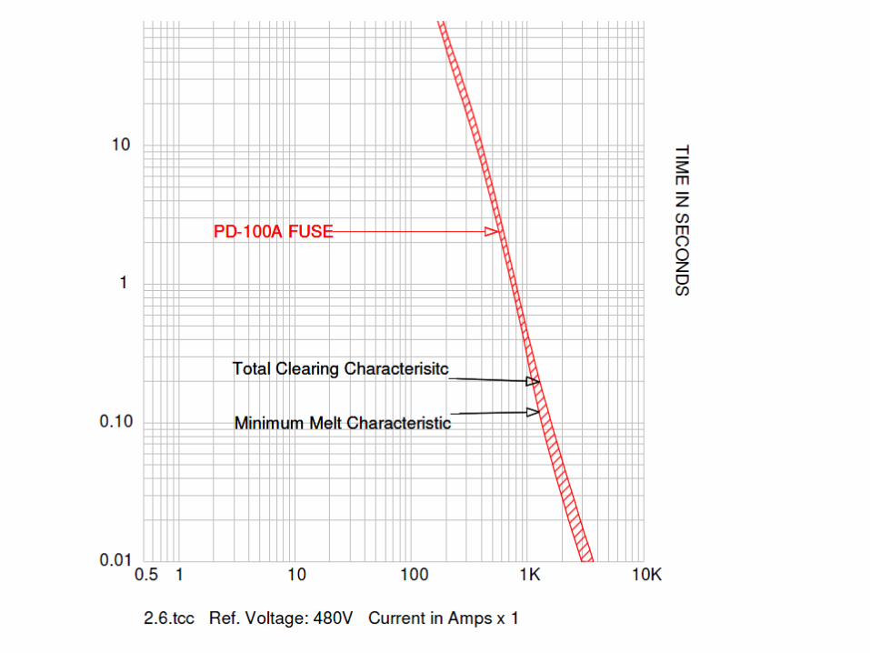
TCC with tolerance band Upper Line of TCC Protection relay single line Relay Time + tolerance + breaker time Fuse TCC (total clearance) Time Fuse TCC (average melt) Time + Tolerance (+15% otherwise) Fuse TCC (min melt) Time + Tolerance (+30% otherwise) CB Clearing time curve Trip unit time + Breaker Clearing (3-5cyls)
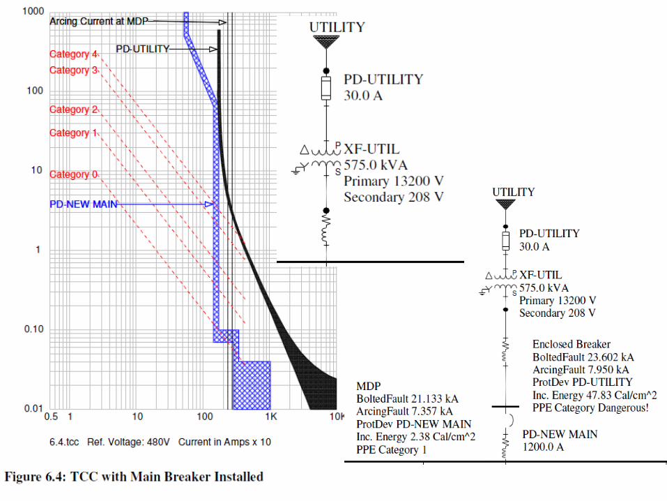
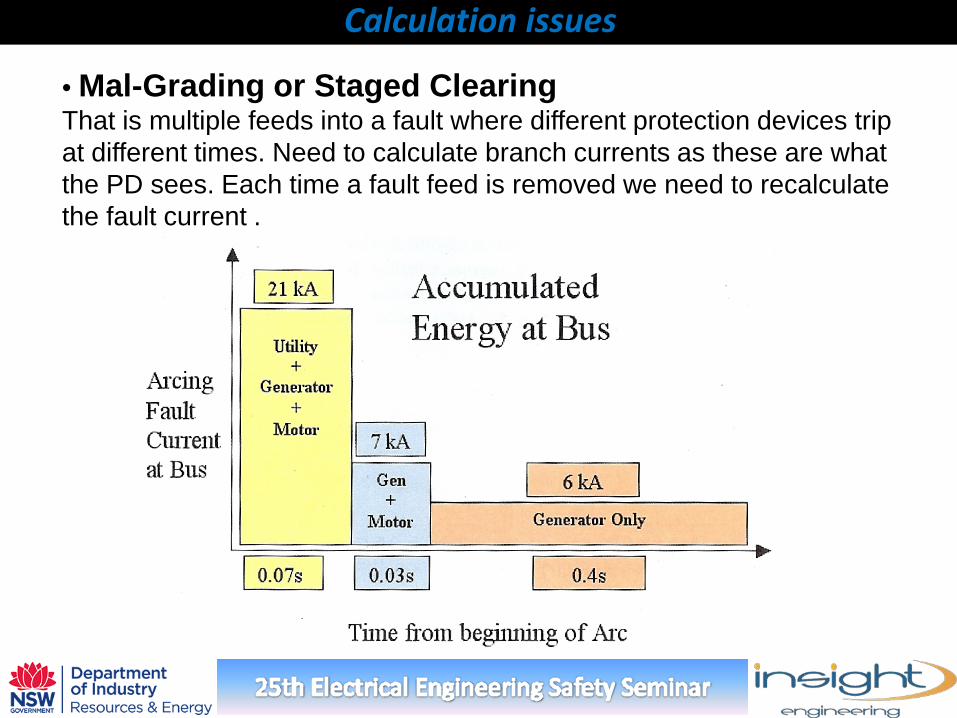
• Mal-Grading or Staged Clearing That is multiple feeds into a fault where different protection devices trip at different times. Need to calculate branch currents as these are what the PD sees. Each time a fault feed is removed we need to recalculate the fault current .
Calculation issues
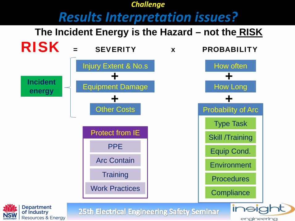
The Incident Energy is the Hazard – not the RISK
RISK = SEVERITY x PROBABILITY
Injury Extent & No.s
Equipment Damage
Other Costs
How often
How Long
Probability of Arc
Type Task
Skill /Training
Equip Cond.
Environment
+ +
+ +
Protect from IE
PPE
Arc Contain
Training
Work Practices
Incident energy
Procedures
Compliance
Challenge Results Interpretation issues?
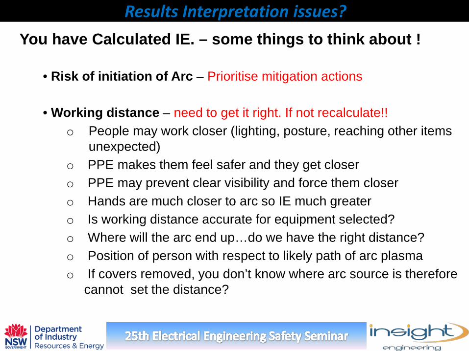
You have Calculated IE. – some things to think about !
• Risk of initiation of Arc – Prioritise mitigation actions • Working distance – need to get it right. If not recalculate!!
o People may work closer (lighting, posture, reaching other items unexpected)
o PPE makes them feel safer and they get closer o PPE may prevent clear visibility and force them closer o Hands are much closer to arc so IE much greater o Is working distance accurate for equipment selected? o Where will the arc end up…do we have the right distance? o Position of person with respect to likely path of arc plasma o If covers removed, you don’t know where arc source is therefore
cannot set the distance?
Results Interpretation issues?
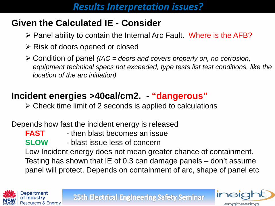
Given the Calculated IE - Consider Panel ability to contain the Internal Arc Fault. Where is the AFB? Risk of doors opened or closed Condition of panel (IAC = doors and covers properly on, no corrosion,
equipment technical specs not exceeded, type tests list test conditions, like the location of the arc initiation)
Incident energies >40cal/cm2. - “dangerous” Check time limit of 2 seconds is applied to calculations
Depends how fast the incident energy is released
FAST - then blast becomes an issue SLOW - blast issue less of concern Low Incident energy does not mean greater chance of containment. Testing has shown that IE of 0.3 can damage panels – don’t assume panel will protect. Depends on containment of arc, shape of panel etc
Results Interpretation issues?
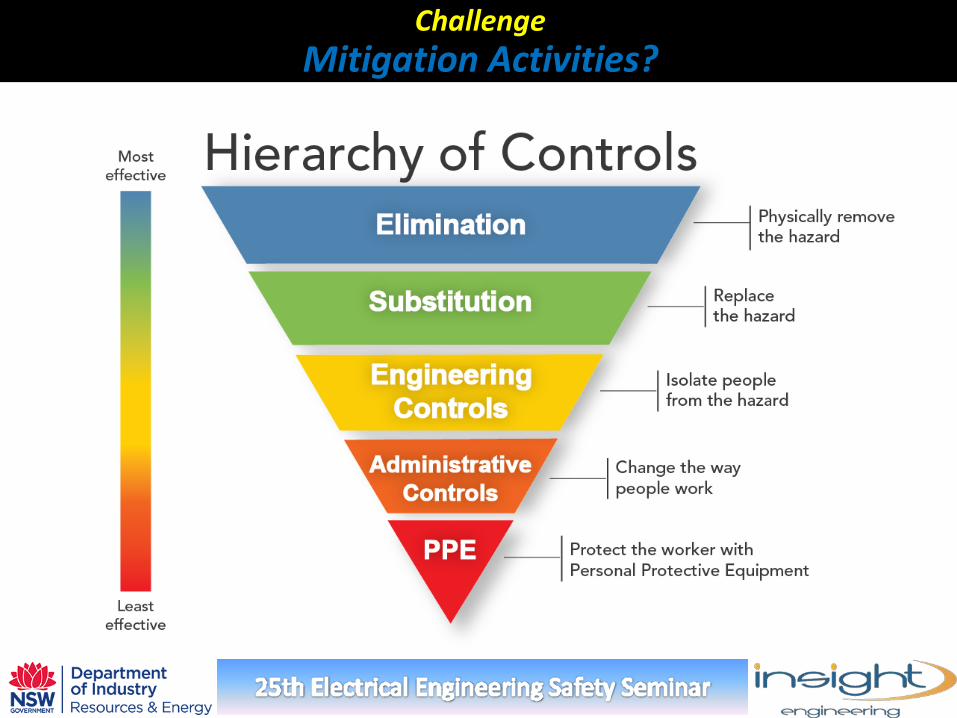
Challenge Mitigation Activities?
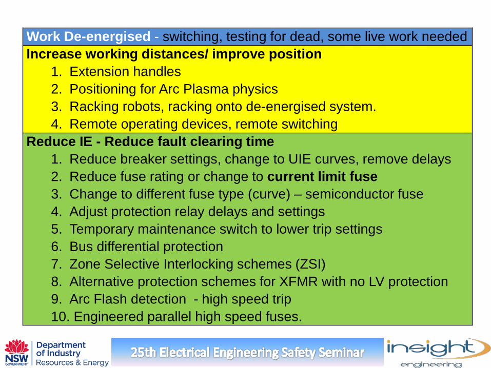
Work De-energised - switching, testing for dead, some live work needed Increase working distances/ improve position
1. Extension handles 2. Positioning for Arc Plasma physics 3. Racking robots, racking onto de-energised system. 4. Remote operating devices, remote switching
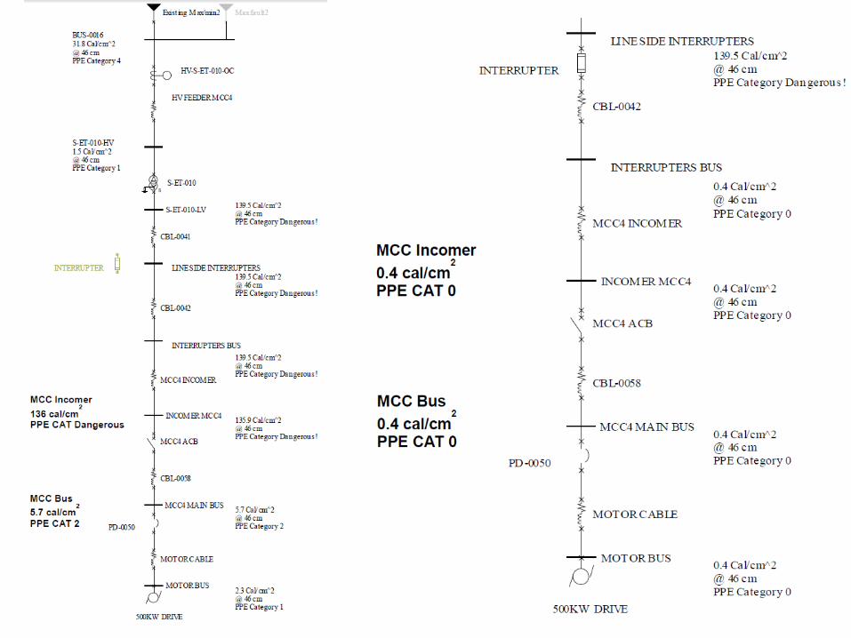
Reduce IE - Reduce fault clearing time 1. Reduce breaker settings, change to UIE curves, remove delays 2. Reduce fuse rating or change to current limit fuse 3. Change to different fuse type (curve) – semiconductor fuse 4. Adjust protection relay delays and settings 5. Temporary maintenance switch to lower trip settings 6. Bus differential protection 7. Zone Selective Interlocking schemes (ZSI) 8. Alternative protection schemes for XFMR with no LV protection 9. Arc Flash detection - high speed trip 10. Engineered parallel high speed fuses.
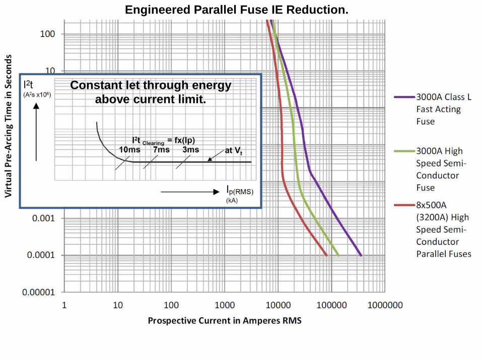
Engineered Parallel Fuse IE Reduction.
Constant let through energy above current limit.
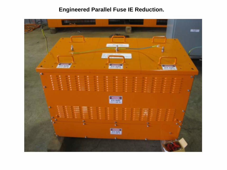
Engineered Parallel Fuse IE Reduction.
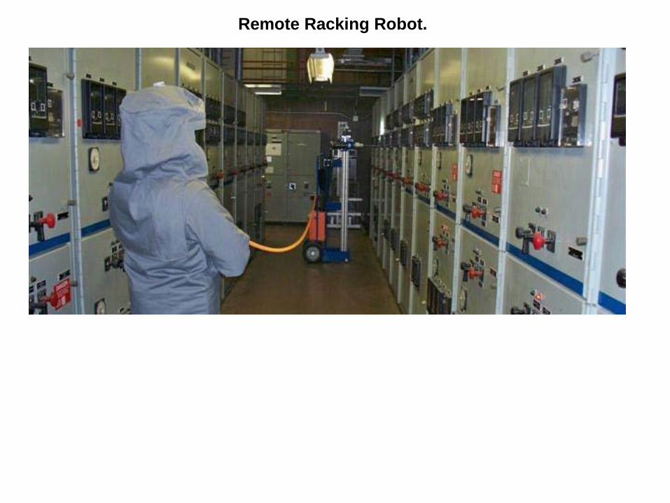
Remote Racking Robot.
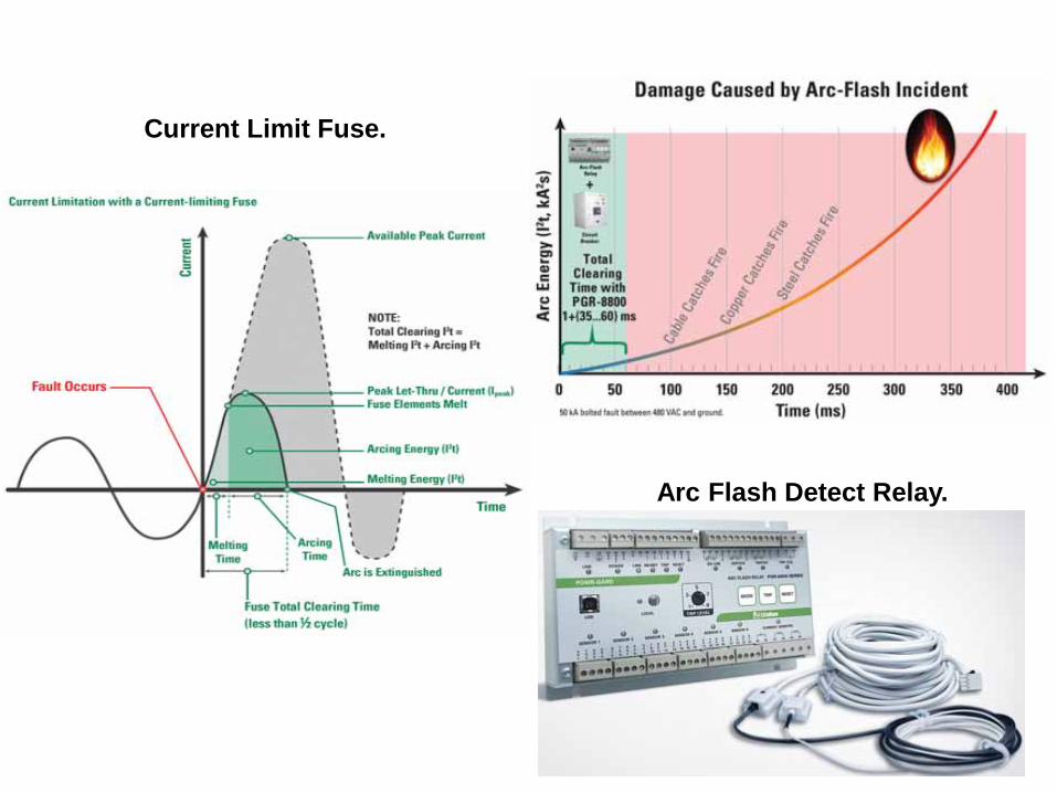
Current Limit Fuse.
Arc Flash Detect Relay.
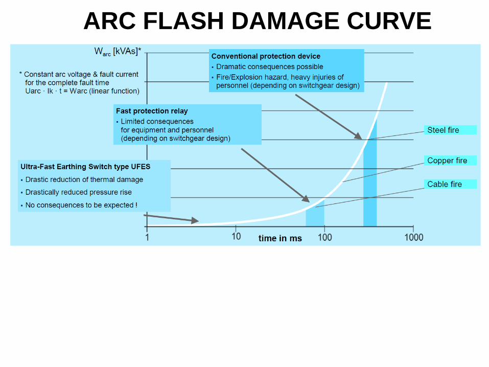
ARC FLASH DAMAGE CURVE
Education – reduce triggers, reduce exposure, maintain system 1. Understand arc flash /blast hazard 2. Understand trigger events 3. Understand mitigation activities - work practices techniques 4. Understand what electrical adjustments make hazard worse 5. Multimeter usage 6. Usage of electrical switchgear 7. Keep panel doors closed
Electrical work practices – reduce triggers, reduce exposure 1. Working de-energised 2. Remote monitoring 3. Reduce pressure/distractions 4. Modify tools used 5. Maintenance setting on protecting device 6. Body position to avoid arc plasma path. (50cal or 5 cal!) 7. Body position while operate panel – let door take heat! 8. Increase working distances
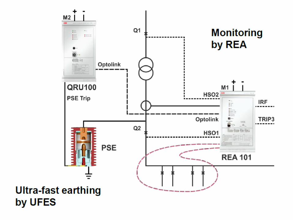
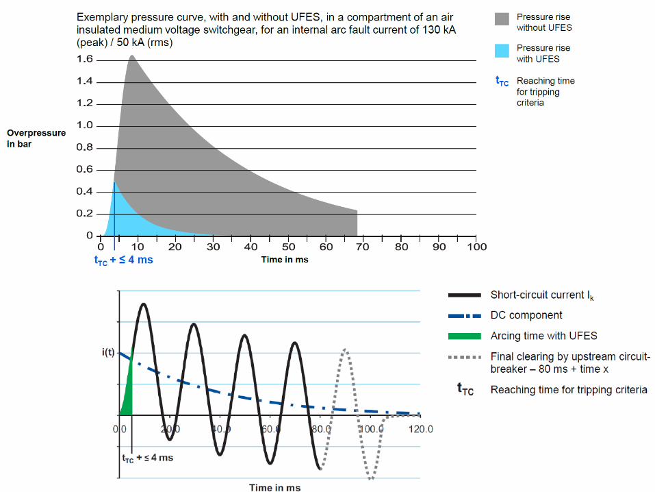
Arc Flash energy capture Detection and Ultra Fast Earthing Switch UFES - “airbag for switchboards”
Switchboard Design - reduce triggers, reduce exposure,
IAC - type tested AS.NZS 3439.1 Annex ZD a. Standard test - downstream of SCPD b. Special test - line side of SCPD or other user specified
Safety by design – withdraw able functional units Partial discharge sensing Form design – segregate control and power IR windows Extra insulation on bus, greater separation, terminal barriers IP2X protection, 24V Control Fused test points on outside of panel Replace non complying high risk switchboards
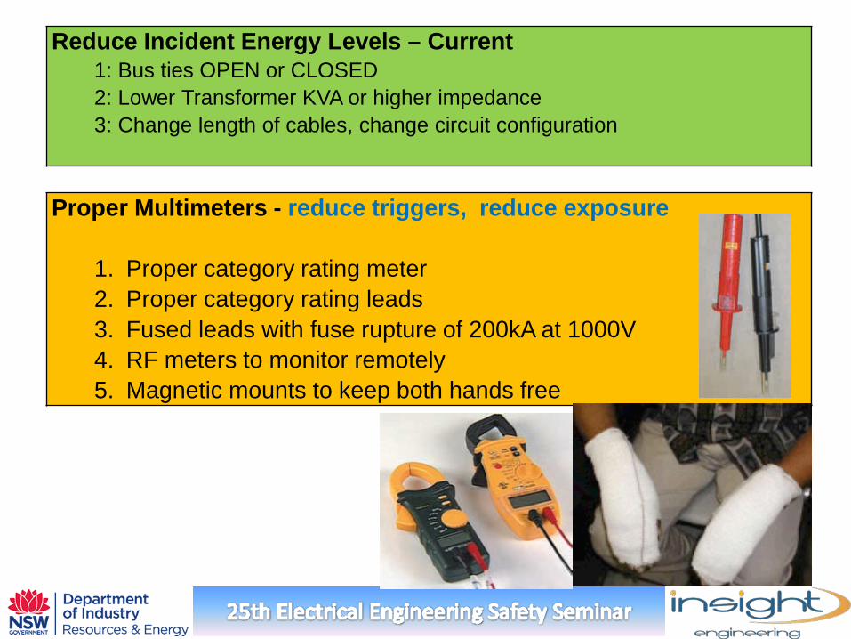
Reduce Incident Energy Levels – Current 1: Bus ties OPEN or CLOSED 2: Lower Transformer KVA or higher impedance 3: Change length of cables, change circuit configuration
Proper Multimeters - reduce triggers, reduce exposure
1. Proper category rating meter 2. Proper category rating leads 3. Fused leads with fuse rupture of 200kA at 1000V 4. RF meters to monitor remotely 5. Magnetic mounts to keep both hands free
Proper Scheduled Maintenance for switchgear - Reduce Arc Flash triggers . Reduce exposure
1. Dust, moisture, rodents, corrosion, humidity, weather 2. Contacts serviced, aligned, tension 3. Arc chutes checked 4. Insulation -SF6, oil levels , oil cleaning, leaks 5. Manufacturers recommended maintenance 6. Protection setting checks and testing 7. Operating within design limits (A,V,Hz,operations,ambient) 8. Replace overstressed equipment (load or PFC) 9. IR monitoring 10.Covers/terminal barriers maintained/ doors closed and all latches
intact, no panel modifications 11.Signage maintained, records of all the above maintained
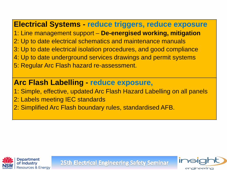
Electrical Systems - reduce triggers, reduce exposure 1: Line management support – De-energised working, mitigation 2: Up to date electrical schematics and maintenance manuals 3: Up to date electrical isolation procedures, and good compliance 4: Up to date underground services drawings and permit systems 5: Regular Arc Flash hazard re-assessment. Arc Flash Labelling - reduce exposure, 1: Simple, effective, updated Arc Flash Hazard Labelling on all panels 2: Labels meeting IEC standards 2: Simplified Arc Flash boundary rules, standardised AFB.
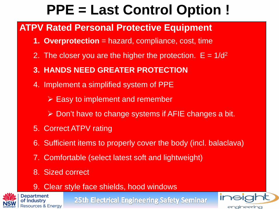
ATPV Rated Personal Protective Equipment 1. Overprotection = hazard, compliance, cost, time
2. The closer you are the higher the protection. E = 1/d2
3. HANDS NEED GREATER PROTECTION
4. Implement a simplified system of PPE
Easy to implement and remember
Don’t have to change systems if AFIE changes a bit.
5. Correct ATPV rating
6. Sufficient items to properly cover the body (incl. balaclava)
7. Comfortable (select latest soft and lightweight)
8. Sized correct
9. Clear style face shields, hood windows
PPE = Last Control Option !
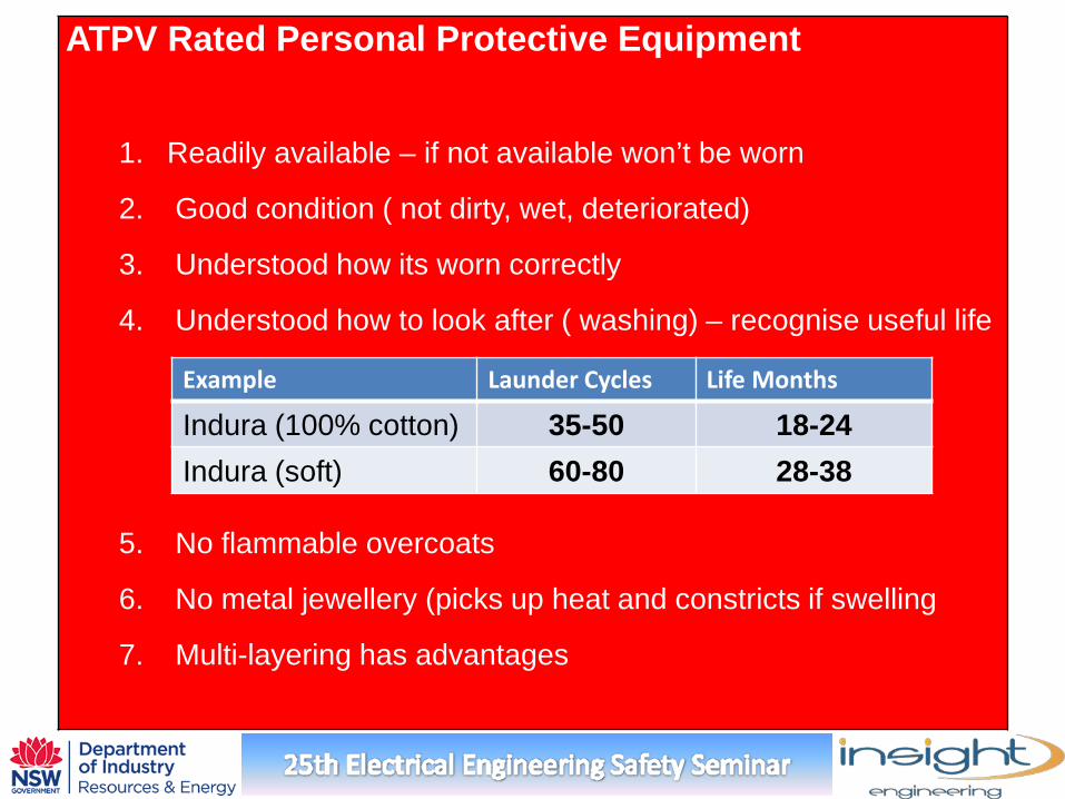
ATPV Rated Personal Protective Equipment
1. Readily available – if not available won’t be worn
2. Good condition ( not dirty, wet, deteriorated)
3. Understood how its worn correctly
4. Understood how to look after ( washing) – recognise useful life
5. No flammable overcoats
6. No metal jewellery (picks up heat and constricts if swelling
7. Multi-layering has advantages
Example Launder Cycles Life Months
Indura (100% cotton) 35-50 18-24 Indura (soft) 60-80 28-38
Challenge
Electrical Worker Culture?
Change mentality Education Support / recognition for safer practices not heroes!!! Recognise need to change
Commitment proven through meaningful action Organisational support crucial What mitigation priorities given illustrates commitment Line management support for de-energised work Reduce time pressures on job planning and completion