Embed Size (px)
DESCRIPTION
จำหน่าย MANN ฟิลเตอร์อุตสาหกรรม และยานยนต์ รายละเอียดเพิ่มเติม ติดต่อ www.FilterTH.com
Citation preview
MANN+HUMMEL Filters for Liquids
2
MANN+HUMMEL Industrial Filters
Also near to you
Our production facilities andsales offices at a number ofEuropean locations, in theUSA, South America and inAsia enable the analysis oftechnical questions on site.One of our subsidiary com-panies or representatives isalso sure to be near to you to enable easy contact.
Modern, high-performancevehicles, machines, equipmentand engines require filtersand components with a corresponding performance.This catalogue provides anoverview of our filters forliquids and the matchingaccessories, naturally all inthe standard MANN+HUMMELOEM quality.
Our customers come frommany varied fields such as:
• Construction machines• Agricultural machines• Compressors• Mechanical engineering• Engine and drive systems• Commercial and special
vehicles, etc.,
This extensive experienceenables MANN+HUMMELto offer individual conceptsand solutions for specialcustomer requirements.
Liquid filters for many applications
How to find your contactpartner:
In order to establish yourcontact partner atMANN+HUMMEL or makecontact with one of our re-presentatives, just call
Tel.: +49 (62 32) 53-80Fax: +49 (62 32) 53-88 99
and tell us your area of ope-rations. We will then imme-diately put you in contact withone of our specialised salesteams.
You can find us in the internetat:www.mann-hummel.comE-Mail: [email protected]
automotive industry and manyother fields. A key area ishigh quality filtration productsfor vehicles, engines andindustrial applications. TheOEM business with globalmarket leaders and produc-ers of vehicles, machinesand installations defines thequality and performance ofthe group. Filters for the
The MANN+HUMMEL Groupis an international companywith its headquarters inLudwigsburg, Germany. Thegroup employs approx. 9500people worldwide at morethan 40 locations.
The company develops, pro-duces and sells technicallycomplex components for the
international aftermarket aresold under numerous inter-national brands as well asunder the MANN-FILTERbrand.
The Industrial Filters BusinessUnit with its headquarters inSpeyer, Germany is special-ised in meeting the require-ments of off-highway vehicle
and - engine applications,compressed air and vacuumtechnology, mechanical engineering and plant construction. For these and other industrial fieldsMANN+HUMMEL IndustrialFilters offers high perfor-mance products for the filtration and separation of air, gases and liquids.
3
Contents
Company profile .................................................................................................................................................. Page 2
Product overview ................................................................................................................................................. Page 4
Spin-on oil filters .................................................................................................................................................. Page 7
In-line oil filters .................................................................................................................................................... Page 15
Overview of oil filter heads .................................................................................................................................. Page 18
Oil filter elements ................................................................................................................................................. Page 33
High pressure filters ............................................................................................................................................ Page 43
Strainer filters ...................................................................................................................................................... Page 51
Centrifuges .......................................................................................................................................................... Page 55
Fuel filters ........................................................................................................................................................... Page 65
Spin-on fuel filters ............................................................................................................................................... Page 68
In-line fuel filters .................................................................................................................................................. Page 73
Overview of fuel filter heads ............................................................................................................................... Page 76
PreLine® in-line fuel filter .................................................................................................................................... Page 78
Fuel filter elements ............................................................................................................................................. Page 87
Gap-type filters ................................................................................................................................................... Page 91
Plate gap-type filters ........................................................................................................................................... Page 94
Wire gap-type filters .......................................................................................................................................... Page 96
Gap-type tube filters ........................................................................................................................................... Page 97
High pressure filters for reaction injection moulding .......................................................................................... Page 99
Accessories for liquid filters ................................................................................................................................ Page 103
Technical annex .................................................................................................................................................. Page 109
Filter terminology ................................................................................................................................................ Page 110
Oil and fuel viscosities ........................................................................................................................................ Page 112
List of contents according to order numbers ...................................................................................................... Page 114
MANN+HUMMEL Industrial Filters worldwide .................................................................................................... Page 118
Notes .................................................................................................................................................................. Page 120
Conversion table (back cover)
4
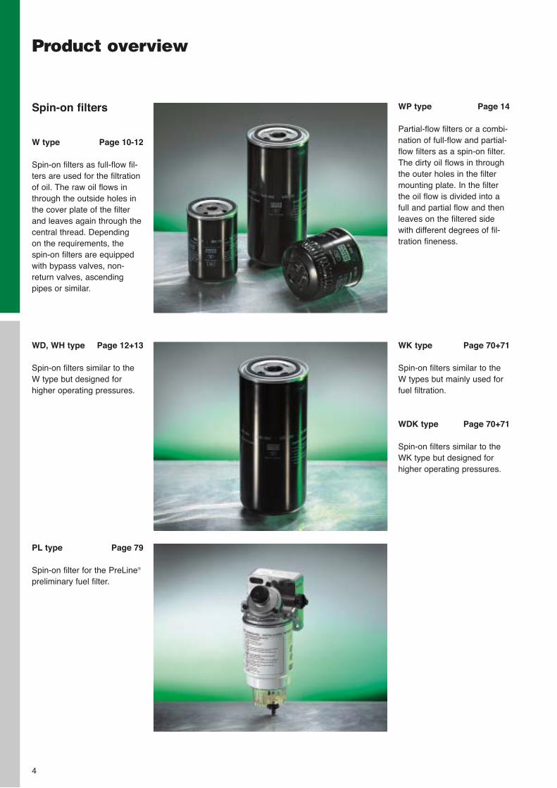
Spin-on filters
W type Page 10-12
Spin-on filters as full-flow fil-ters are used for the filtrationof oil. The raw oil flows inthrough the outside holes inthe cover plate of the filterand leaves again through thecentral thread. Depending on the requirements, thespin-on filters are equippedwith bypass valves, non-return valves, ascendingpipes or similar.
Product overview
WD, WH type Page 12+13
Spin-on filters similar to theW type but designed for higher operating pressures.
PL type Page 79
Spin-on filter for the PreLine®
preliminary fuel filter.
WP type Page 14
Partial-flow filters or a combi-nation of full-flow and partial-flow filters as a spin-on filter.The dirty oil flows in throughthe outer holes in the filtermounting plate. In the filterthe oil flow is divided into afull and partial flow and thenleaves on the filtered sidewith different degrees of fil-tration fineness.
WK type Page 70+71
Spin-on filters similar to theW types but mainly used forfuel filtration.
WDK type Page 70+71
Spin-on filters similar to theWK type but designed forhigher operating pressures.
5
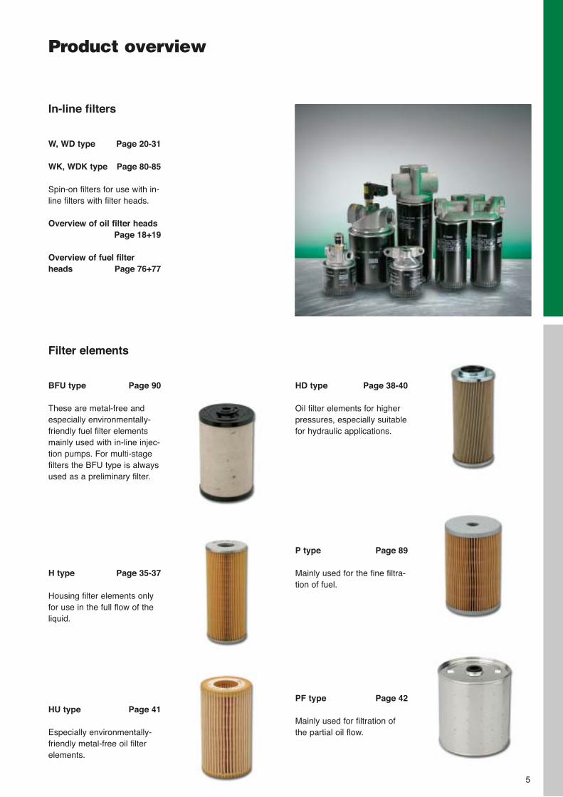
In-line filters
W, WD type Page 20-31
WK, WDK type Page 80-85
Spin-on filters for use with in-line filters with filter heads.
Overview of oil filter headsPage 18+19
Overview of fuel filterheads Page 76+77
HD type Page 38-40
Oil filter elements for higherpressures, especially suitablefor hydraulic applications.
P type Page 89
Mainly used for the fine filtra-tion of fuel.
PF type Page 42
Mainly used for filtration ofthe partial oil flow.
Filter elements
BFU type Page 90
These are metal-free andespecially environmentally-friendly fuel filter elementsmainly used with in-line injec-tion pumps. For multi-stagefilters the BFU type is alwaysused as a preliminary filter.
H type Page 35-37
Housing filter elements onlyfor use in the full flow of theliquid.
HU type Page 41
Especially environmentally-friendly metal-free oil filterelements.
Product overview
6
Product overview
Centrifuges Page 55
Centrifuges have an externalhousing cover and a centralspindle around which a rotorturns at high speed. Theresulting centrifugal forceserves to separate the finestparticles (soot) from the lubeoil. Centrifuges are partial-flow filters and are operatedin combination with a full-flowfilter.
Gap-type filters Page 91
Gap-type filters always findapplication when coarse par-ticles have to be separatedfrom heavily contaminatedliquids. These are surface-type filters. During normaloperation a filter cake formswhich is cleaned awaymanually or with the supportof a motor.
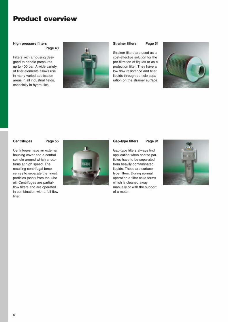
High pressure filters Page 43
Filters with a housing desi-gned to handle pressures up to 400 bar. A wide varietyof filter elements allows usein many varied applicationareas in all industrial fields,especially in hydraulics.
Strainer filters Page 51
Strainer filters are used as acost-effective solution for thepre-filtration of liquids or as aprotection filter. They have alow flow resistance and filterliquids through particle sepa-ration on the strainer surface.
MANN+HUMMEL Spin-on oil filters
7
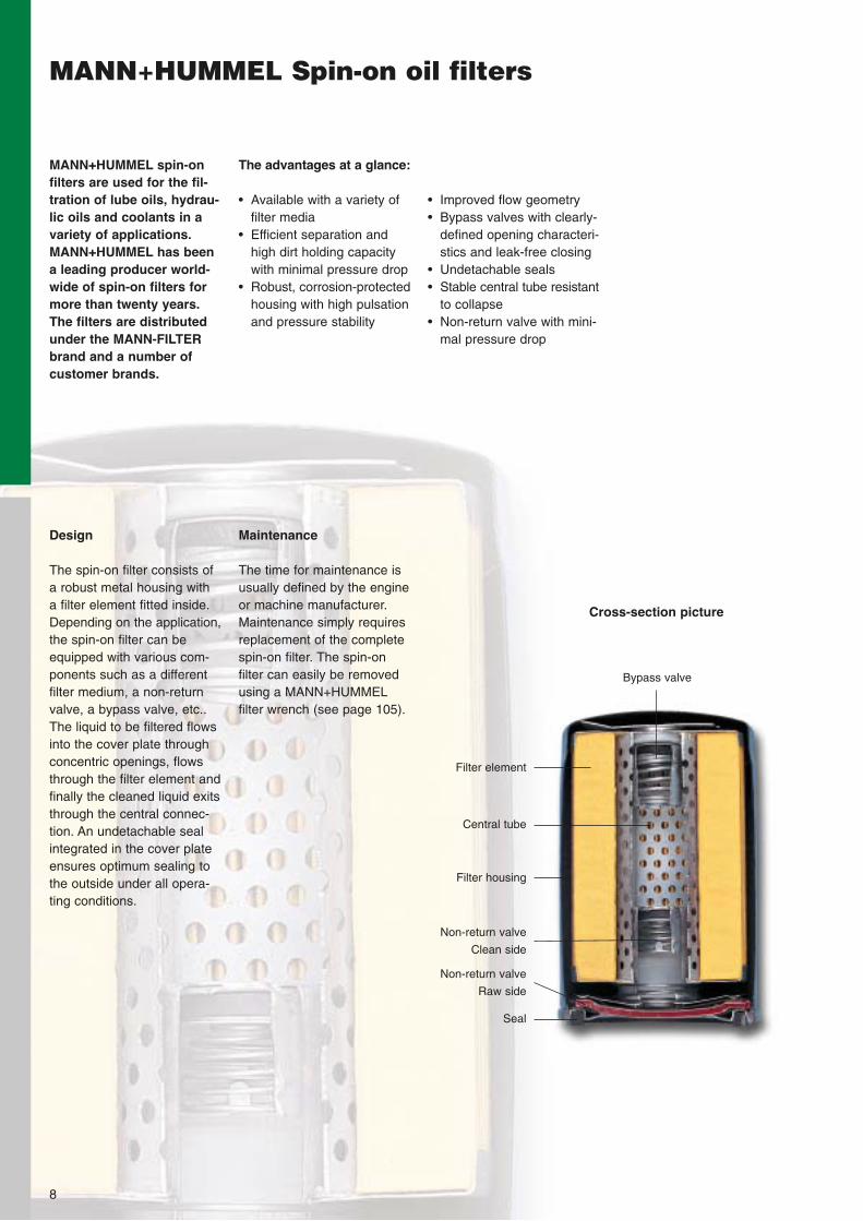
Filter element
Central tube
Filter housing
Seal
The advantages at a glance:
• Available with a variety offilter media
• Efficient separation andhigh dirt holding capacitywith minimal pressure drop
• Robust, corrosion-protectedhousing with high pulsationand pressure stability
MANN+HUMMEL spin-onfilters are used for the fil-tration of lube oils, hydrau-lic oils and coolants in avariety of applications.MANN+HUMMEL has beena leading producer world-wide of spin-on filters formore than twenty years.The filters are distributedunder the MANN-FILTERbrand and a number ofcustomer brands.
8
• Improved flow geometry• Bypass valves with clearly-
defined opening characteri-stics and leak-free closing
• Undetachable seals• Stable central tube resistant
to collapse• Non-return valve with mini-
mal pressure drop
MANN+HUMMEL Spin-on oil filters
Maintenance
The time for maintenance isusually defined by the engineor machine manufacturer.Maintenance simply requiresreplacement of the completespin-on filter. The spin-on filter can easily be removedusing a MANN+HUMMELfilter wrench (see page 105).
Design
The spin-on filter consists ofa robust metal housing with a filter element fitted inside.Depending on the application,the spin-on filter can beequipped with various com-ponents such as a differentfilter medium, a non-returnvalve, a bypass valve, etc..The liquid to be filtered flowsinto the cover plate throughconcentric openings, flowsthrough the filter element andfinally the cleaned liquid exitsthrough the central connec-tion. An undetachable sealintegrated in the cover plateensures optimum sealing tothe outside under all opera-ting conditions.
Bypass valve
Non-return valve
Clean side
Cross-section picture
Non-return valve
Raw side
9
MANN+HUMMEL Spin-on oil filters
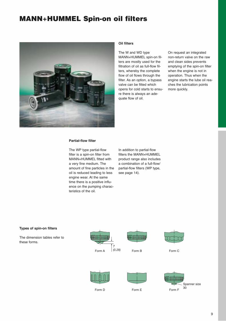
Oil filters
The W and WD typeMANN+HUMMEL spin-on fil-ters are mostly used for thefiltration of oil as full-flow fil-ters, whereby the completeflow of oil flows through thefilter. As an option, a bypassvalve can be fitted whichopens for cold starts to ensu-re there is always an ade-quate flow of oil.
On request an integratednon-return valve on the rawand clean sides preventsemptying of the spin-on filterwhen the engine is not inoperation. Thus when theengine starts the lube oil rea-ches the lubrication pointsmore quickly.
Partial-flow filter
The WP type partial-flow filter is a spin-on filter fromMANN+HUMMEL fitted witha very fine medium. Theamount of fine particles in theoil is reduced leading to lessengine wear. At the sametime there is a positive influ-ence on the pumping charac-teristics of the oil.
In addition to partial-flow filters the MANN+HUMMELproduct range also includes a combination of a full-flow/partial-flow filters (WP type,see page 14).
Types of spin-on filters
The dimension tables refer tothese forms.
Form A
Form D
Form B
Form E
Form C
Form F
7(0.28)
Spanner size30
10
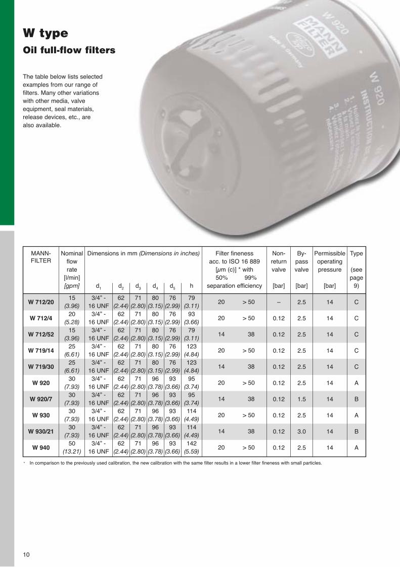
The table below lists selectedexamples from our range offilters. Many other variationswith other media, valveequipment, seal materials,release devices, etc., arealso available.
W typeOil full-flow filters
W 712/20
W 712/4
W 712/52
W 719/14
W 719/30
W 920
W 920/7
W 930
W 930/21
W 940
MANN-FILTER
Dimensions in mm (Dimensions in inches)
d1
3/4” - 16 UNF3/4” -
16 UNF3/4” -
16 UNF3/4” -
16 UNF3/4” -
16 UNF3/4” -
16 UNF3/4” -
16 UNF3/4” -
16 UNF3/4” -
16 UNF3/4” -
16 UNF
d2
62(2.44)
62(2.44)
62(2.44)
62(2.44)
62(2.44)
62(2.44)
62(2.44)
62(2.44)
62(2.44)
62(2.44)
d3
71(2.80)
71(2.80)
71(2.80)
71(2.80)
71(2.80)
71(2.80)
71(2.80)
71(2.80)
71(2.80)
71(2.80)
d4
80(3.15)
80(3.15)
80(3.15)
80(3.15)
80(3.15)
96(3.78)
96(3.78)
96(3.78)
96(3.78)
96(3.78)
d5
76(2.99)
76(2.99)
76(2.99)
76(2.99)
76(2.99)
93(3.66)
93(3.66)
93(3.66)
93(3.66)
93(3.66)
h
79(3.11)
93(3.66)
79(3.11)123
(4.84)123
(4.84)95
(3.74)95
(3.74)114
(4.49)114
(4.49)142
(5.59)
Non-returnvalve
[bar]
–
0.12
0.12
0.12
0.12
0.12
0.12
0.12
0.12
0.12
By-pass valve
[bar]
2.5
2.5
2.5
2.5
2.5
2.5
1.5
2.5
3.0
2.5
Permissibleoperatingpressure
[bar]
14
14
14
14
14
14
14
14
14
14
Type
(seepage
9)
C
C
C
C
C
A
B
A
B
A
Nominalflow rate
[l/min][gpm]
15(3.96)
20(5.28)
15(3.96)
25(6.61)
25(6.61)
30(7.93)
30(7.93)
30(7.93)
30(7.93)
50(13.21)
Filter fineness acc. to ISO 16 889
[µm (c)] * with50% 99%
separation efficiency
20 > 50
20 > 50
14 38
20 > 50
14 38
20 > 50
14 38
20 > 50
14 38
20 > 50
* In comparison to the previously used calibration, the new calibration with the same filter results in a lower filter fineness with small particles.
11
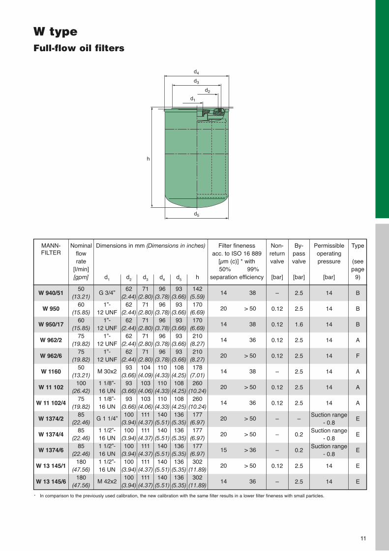
W typeFull-flow oil filters
d4
h
d3
d2
d1
d5
W 940/51
W 950
W 950/17
W 962/2
W 962/6
W 1160
W 11 102
W 11 102/4
W 1374/2
W 1374/4
W 1374/6
W 13 145/1
W 13 145/6
MANN-FILTER
Dimensions in mm (Dimensions in inches)
d1
G 3/4”
1”-12 UNF
1”-12 UNF
1”-12 UNF
1”-12 UNF
M 30x2
1 1/8”-16 UN1 1/8”-16 UN
G 1 1/4”
1 1/2”-16 UN1 1/2”-16 UN1 1/2”-16 UN
M 42x2
d2
62(2.44)
62(2.44)
62(2.44)
62(2.44)
62(2.44)
93(3.66)
93(3.66)
93(3.66)100
(3.94)100
(3.94)100
(3.94)100
(3.94)100
(3.94)
d3
71(2.80)
71(2.80)
71(2.80)
71(2.80)
71(2.80)104
(4.09)103
(4.06)103
(4.06)111
(4.37)111
(4.37)111
(4.37)111
(4.37)111
(4.37)
d4
96(3.78)
96(3.78)
96(3.78)
96(3.78)
96(3.78)110
(4.33)110
(4.33)110
(4.33)140
(5.51)140
(5.51)140
(5.51)140
(5.51)140
(5.51)
d5
93(3.66)
93(3.66)
93(3.66)
93(3.66)
93(3.66)108
(4.25)108
(4.25)108
(4.25)136
(5.35)136
(5.35)136
(5.35)136
(5.35)136
(5.35)
h
142(5.59)170
(6.69)170
(6.69)210
(8.27)210
(8.27)178
(7.01)260
(10.24)260
(10.24)177
(6.97)177
(6.97)177
(6.97)302
(11.89)302
(11.89)
Non-returnvalve
[bar]
–
0.12
0.12
0.12
0.12
–
0.12
0.12
–
–
–
0.12
–
By-passvalve
[bar]
2.5
2.5
1.6
2.5
2.5
2.5
2.5
2.5
–
0.2
0.2
2.5
2.5
Permissibleoperatingpressure
[bar]
14
14
14
14
14
14
14
14
Suction range- 0.8
Suction range- 0.8
Suction range- 0.8
14
14
Type
(seepage
9)
B
B
B
A
F
A
A
A
E
E
E
E
E
Nominalflow rate
[l/min][gpm]
50(13.21)
60(15.85)
60(15.85)
75(19.82)
75(19.82)
50(13.21)
100(26.42)
75(19.82)
85(22.46)
85(22.46)
85(22.46)
180(47.56)
180(47.56)
Filter fineness acc. to ISO 16 889
[µm (c)] * with50% 99%
separation efficiency
14 38
20 > 50
14 38
14 36
20 > 50
14 38
20 > 50
14 36
20 > 50
20 > 50
15 > 36
20 > 50
14 36
* In comparison to the previously used calibration, the new calibration with the same filter results in a lower filter fineness with small particles.
12
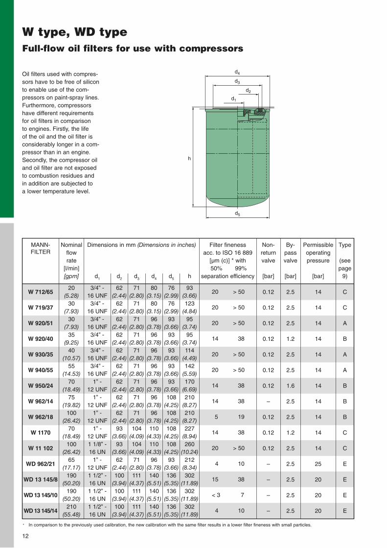
W type, WD typeFull-flow oil filters for use with compressors
d4
h
d3
d2
d1
d5
W 712/65
W 719/37
W 920/51
W 920/40
W 930/35
W 940/55
W 950/24
W 962/14
W 962/18
W 1170
W 11 102
WD 962/21
WD 13 145/8
WD 13 145/10
WD 13 145/14
MANN-FILTER
Dimensions in mm (Dimensions in inches)
d1
3/4” - 16 UNF3/4” -
16 UNF3/4” -
16 UNF3/4” -
16 UNF3/4” -
16 UNF3/4” -
16 UNF1” -
12 UNF1” -
12 UNF1” -
12 UNF1” -
12 UNF1 1/8” - 16 UN
1” - 12 UNF1 1/2” - 16 UN1 1/2” - 16 UN1 1/2” - 16 UN
d2
62(2.44)
62(2.44)
62(2.44)
62(2.44)
62(2.44)
62(2.44)
62(2.44)
62(2.44)
62(2.44)
93(3.66)
93(3.66)
62(2.44)100
(3.94)100
(3.94)100
(3.94)
d3
71(2.80)
71(2.80)
71(2.80)
71(2.80)
71(2.80)
71(2.80)
71(2.80)
71(2.80)
71(2.80)104
(4.09)104
(4.09)71
(2.80)111
(4.37)111
(4.37)111
(4.37)
d4
80(3.15)
80(3.15)
96(3.78)
96(3.78)
96(3.78)
96(3.78)
96(3.78)
96(3.78)
96(3.78)110
(4.33)110
(4.33)96
(3.78)140
(5.51)140
(5.51)140
(5.51)
d5
76(2.99)
76(2.99)
93(3.66)
93(3.66)
93(3.66)
93(3.66)
93(3.66)108
(4.25)108
(4.25)108
(4.25)108
(4.25)93
(3.66)136
(5.35)136
(5.35)136
(5.35)
h
93(3.66)123
(4.84)95
(3.74)95
(3.74)114
(4.49)142
(5.59)170
(6.69)210
(8.27)210
(8.27)227
(8.94)260
(10.24)212
(8.34)302
(11.89)302
(11.89)302
(11.89)
Non-returnvalve
[bar]
0.12
0.12
0.12
0.12
0.12
0.12
0.12
–
0.12
0.12
0.12
–
–
–
–
By-pass valve
[bar]
2.5
2.5
2.5
1.2
2.5
2.5
1.6
2.5
2.5
1.2
2.5
2.5
2.5
2.5
2.5
Permissibleoperatingpressure
[bar]
14
14
14
14
14
14
14
14
14
14
14
25
20
20
20
Type
(seepage
9)
C
C
A
B
A
A
B
B
B
C
C
E
E
E
E
Nominalflow rate
[l/min][gpm]
20(5.28)
30(7.93)
30(7.93)
35(9.25)
40(10.57)
55(14.53)
70(18.49)
75(19.82)
100(26.42)
70(18.49)
100(26.42)
65(17.17)
190(50.20)
190(50.20)
210(55.48)
Filter fineness acc. to ISO 16 889
[µm (c)] * with50% 99%
separation efficiency
20 > 50
20 > 50
20 > 50
14 38
20 > 50
20 > 50
14 38
14 38
5 19
14 38
20 > 50
4 10
15 38
< 3 7
4 10
Oil filters used with compres-sors have to be free of siliconto enable use of the com-pressors on paint-spray lines.Furthermore, compressorshave different requirementsfor oil filters in comparison to engines. Firstly, the life of the oil and the oil filter isconsiderably longer in a com-pressor than in an engine.Secondly, the compressor oiland oil filter are not exposedto combustion residues andin addition are subjected to a lower temperature level.
* In comparison to the previously used calibration, the new calibration with the same filter results in a lower filter fineness with small particles.
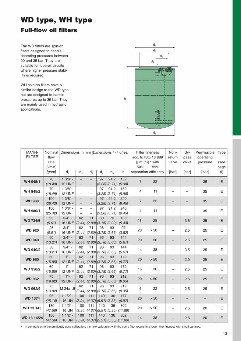
WD type, WH typeFull-flow oil filters
d4
h
d3
d2
d1
d5
The WD filters are spin-on filters designed to handleoperating pressures between20 and 35 bar. They are suitable for lube-oil circuitswhere higher pressure stabi-lity is required.
WH spin-on filters have asimilar design to the WD typebut are designed to handlepressures up to 35 bar. Theyare mainly used in hydraulicapplications.
WH 945/1
WH 945/2
WH 980
WH 980/1
WD 724/6
WD 920
WD 940
WD 940/2
WD 950
WD 950/2
WD 962
WD 962/9
WD 1374
WD 13 145
WD 13 145/4
MANN-FILTER
Dimensions in mm (Dimensions in inches)
d1
1 3/8” - 12 UNF1 3/8” - 12 UNF1 3/8” - 12 UNF1 3/8” - 12 UNF3/4” -
16 UNF3/4” -
16 UNF3/4” -
16 UNF3/4” -
16 UNF1”-
12 UNF1”-
12 UNF1”-
12 UNF
M 24x1.5
1 1/2” - 16 UN1 1/2” -16 UN1 1/2” -16 UN
d2
––––––––
62(2.44)
62(2.44)
62(2.44)
62(2.44)
62(2.44)
62(2.44)
62(2.44)
62(2.44)100
(3.94)100
(3.94)100
(3.94)
d3
––––––––
71(2.80)
71(2.80)
71(2.80)
71(2.80)
71(2.80)
71(2.80)
71(2.80)
71(2.80)111
(4.37)111
(4.37)111
(4.37)
d4
97(3.28)
97(3.28)
97(3.28)
97(3.28)
80(3.15)
96(3.78)
96(3.78)
96(3.78)
96(3.78)
96(3.78)
96(3.78)
96(3.78)140
(5.51)140
(5.51)140
(5.51)
d5
94.2(3.71)94.2(3.71)94.2(3.71)94.2(3.71)
76(2.99)
93(3.66)
93(3.66)
93(3.66)
93(3.66)
93(3.66)
93(3.66)
93(3.66)136
(5.35)136
(5.35)136
(5.35)
h
152(5.98)152
(5.98)240
(9.45)240
(9.45)138
(5.43)97
(3.82)144
(5.67)144
(5.67)172
(6.77)172
(6.77)212
(8.35)212
(8.35)177
(6.97)302
(11.89)302
(11.89)
Non-returnvalve
[bar]
–
–
–
–
–
–
–
–
–
–
–
–
–
–
–
By-pass valve
[bar]
–
–
–
–
3.5
2.5
2.5
3.5
2.5
2.5
2.5
2.5
–
2.5
2.5
Permissibleoperatingpressure
[bar]
35
35
35
35
35
25
25
25
25
25
25
25
–
20
20
Type
(seepage
9)
E
E
E
E
E
E
E
E
E
E
E
E
E
E
E
Nominalflow rate
[l/min][gpm]
70(18.49)
70(18.49)
100(26.42)
100(26.42)
25(6.61)
25(6.61)
50(13.21)
50(13.21)
60(15.85)
60(15.85)
75(19.82)
75(19.82)
95(25.10)
180(47.56)
180(47.56)
Filter fineness acc. to ISO 16 889
[µm (c)] * with50% 99%
separation efficiency
7 22
4 11
7 22
4 11
11 28
20 > 50
20 50
14 38
20 > 50
15 36
20 > 50
6 22
20 > 50
20 > 50
14 38
13
* In comparison to the previously used calibration, the new calibration with the same filter results in a lower filter fineness with small particles.
14
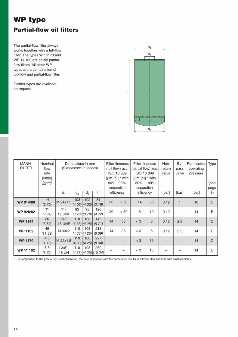
WP typePartial-flow oil filters
The partial-flow filter alwaysworks together with a full-flowfilter. The types WP 1170 andWP 11 102 are solely partial-flow filters. All other WPtypes are a combination offull-flow and partial-flow filter.
Further types are availableon request.
WP 914/80
WP 928/82
WP 1144
WP 1169
WP 1170
WP 11 102
MANN-FILTER
Dimensions in mm(Dimensions in inches)
d1
M 24x1.5
1” -12 UNF3/4” -
16 UNF
M 30x2
M 22x1.5
1 3/8” - 16 UN
d4
103(4.06)
93(3.78)110
(4.33)110
(4.33)110
(4.33)110
(4.33)
d5
102(4.02)
93(3.78)108
(4.25)108
(4.25)108
(4.25)108
(4.25)
h
81(3.19)120
(4.72)145
(5.71)213
(8.39)227
(8.94)260
(10.24)
Non-returnvalve
[bar]
0.12
0.12
0.12
0.12
–
–
By-passvalve
[bar]
1
–
2.5
2.5
–
–
Permissibleoperatingpressure
[bar]
10
14
14
14
14
14
Type
(seepage
9)
C
E
C
C
C
C
Nominalflow rate
[l/min][gpm]
14(3.70)
11(2.91)
26(6.87)
45(11.89)
4.5(1.19)6.5
(1.72)
Filter fineness(full flow) acc. ISO 16 889
[µm (c)] * with50% 99%separation efficiency
20 > 50
20 > 50
14 36
14 36
– –
– –
Filter fineness(partial flow) acc.
ISO 16 889[µm (c)] * with50% 99%separation efficiency
14 38
5 19
< 3 6
< 3 6
< 3 15
< 3 15
d4
h
d1
d5
* In comparison to the previously used calibration, the new calibration with the same filter results in a lower filter fineness with small particles.
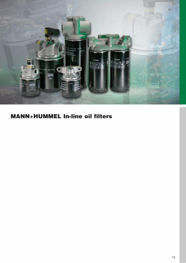
MANN+HUMMEL In-line oil filters
15
MANN+HUMMEL In-line oil filters
The advantages at a glance:
• Easy to fit to existing lines• Solid and stable cast
aluminium construction• Increased flexibility availa-
ble for standard versionwith option of optical orelectrical service switch(see pages 106 107)
MANN+HUMMEL in-line filters are used mainly inhydraulic systems, for thefiltration of engine andgearbox oil, and in lube-oilcircuits in general mecha-nical engineering applica-tions. The range of filtersincludes filters with singleheads, duplex filters with-out changeover, duplex filters with changeover,and large triplex oil filters.The filtration characteristicsdepend on the respectivespin-on filter and used filtermedium.
• Duplex types with change-over available
• Minimal pressure drop• Proven quality of
MANN+HUMMEL spin-onfilters
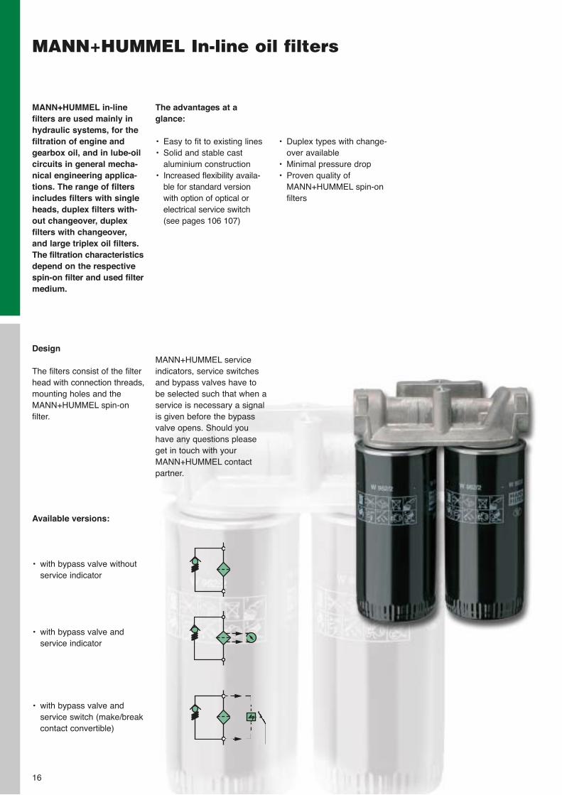
Design
The filters consist of the filterhead with connection threads,mounting holes and theMANN+HUMMEL spin-on filter.
Available versions:
• with bypass valve withoutservice indicator
• with bypass valve and service indicator
• with bypass valve and service switch (make/breakcontact convertible)
MANN+HUMMEL serviceindicators, service switchesand bypass valves have tobe selected such that when aservice is necessary a signalis given before the bypassvalve opens. Should youhave any questions pleaseget in touch with yourMANN+HUMMEL contactpartner.
16
17
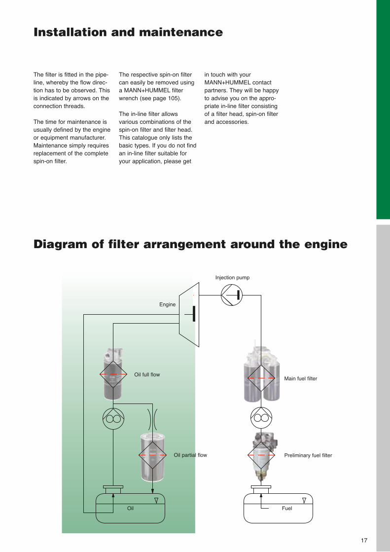
Main fuel filter
Preliminary fuel filter
Oil full flow
Oil partial flow
Injection pump
Engine
Oil Fuel
Installation and maintenance
The filter is fitted in the pipe-line, whereby the flow direc-tion has to be observed. Thisis indicated by arrows on theconnection threads.
The time for maintenance isusually defined by the engineor equipment manufacturer.Maintenance simply requiresreplacement of the completespin-on filter.
The respective spin-on filtercan easily be removed usinga MANN+HUMMEL filterwrench (see page 105).
The in-line filter allowsvarious combinations of thespin-on filter and filter head.This catalogue only lists thebasic types. If you do not findan in-line filter suitable foryour application, please get
in touch with yourMANN+HUMMEL contactpartners. They will be happyto advise you on the appro-priate in-line filter consistingof a filter head, spin-on filterand accessories.
Diagram of filter arrangement around the engine
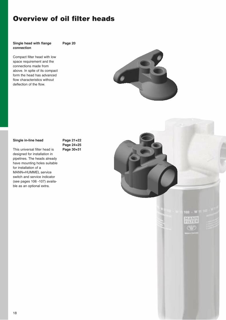
Single head with flangeconnection
Compact filter head with lowspace requirement and theconnections made fromabove. In spite of its compactform the head has advancedflow characteristics withoutdeflection of the flow.
Overview of oil filter heads
Single in-line head
This universal filter head isdesigned for installation inpipelines. The heads alreadyhave mounting holes suitablefor installation of aMANN+HUMMEL serviceswitch and service indicator(see pages 106 -107) availa-ble as an optional extra.
18
Page 20
Page 21+22Page 24+25Page 30+31
Overview of oil filter heads
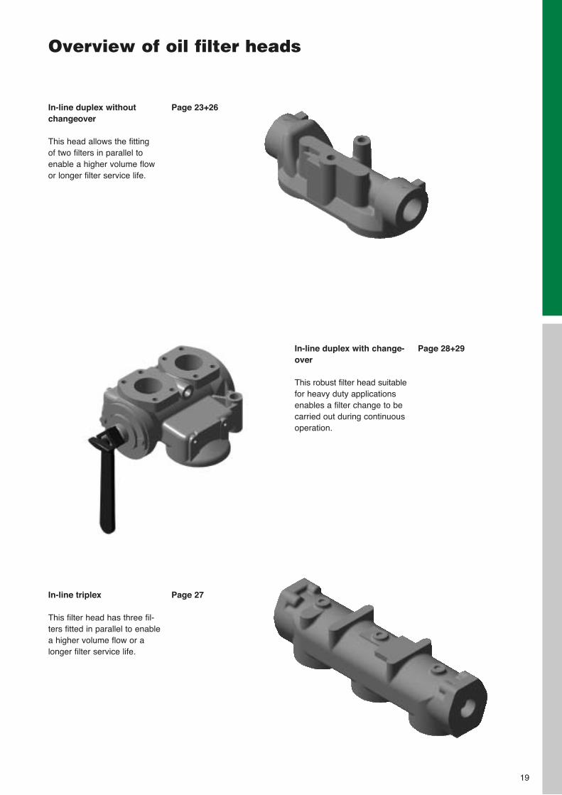
In-line duplex withoutchangeover
This head allows the fitting of two filters in parallel toenable a higher volume flowor longer filter service life.
In-line triplex
This filter head has three fil-ters fitted in parallel to enablea higher volume flow or alonger filter service life.
In-line duplex with change-over
This robust filter head suitablefor heavy duty applicationsenables a filter change to becarried out during continuousoperation.
19
Page 23+26
Page 27
Page 28+29
20
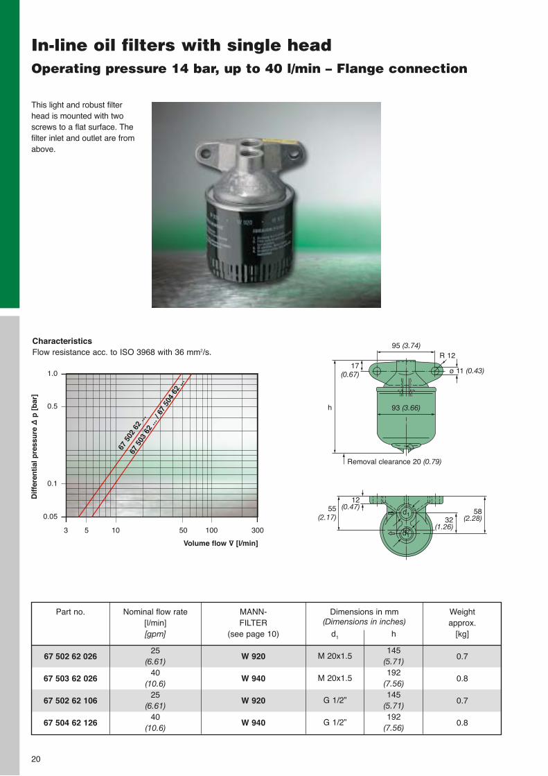
In-line oil filters with single headOperating pressure 14 bar, up to 40 l/min – Flange connection
This light and robust filterhead is mounted with two screws to a flat surface. Thefilter inlet and outlet are fromabove.
67 502 62 026
67 503 62 026
67 502 62 106
67 504 62 126
Part no. Dimensions in mm (Dimensions in inches)
d1
M 20x1.5
M 20x1.5
G 1/2”
G 1/2”
h
145(5.71)192
(7.56)145
(5.71)192
(7.56)
Weight approx.
[kg]
0.7
0.8
0.7
0.8
Nominal flow rate[l/min][gpm]
25(6.61)
40(10.6)
25(6.61)
40(10.6)
MANN-FILTER
(see page 10)
W 920
W 940
W 920
W 940
h
17(0.67)
95 (3.74)
ø 11 (0.43)
R 12
93 (3.66)
12(0.47)55
(2.17)58
(2.28)32(1.26)
d1
d1
CharacteristicsFlow resistance acc. to ISO 3968 with 36 mm2/s.
Volume flow V̇ [l/min]
Dif
fere
nti
al p
ress
ure
∆p
[b
ar]
1.0
0.5
0.1
0.05
3 5 10 50 100 300
67 5
02 6
2 ...
67 5
03 6
2 ...
/ 67
504
62
...
Removal clearance 20 (0.79)
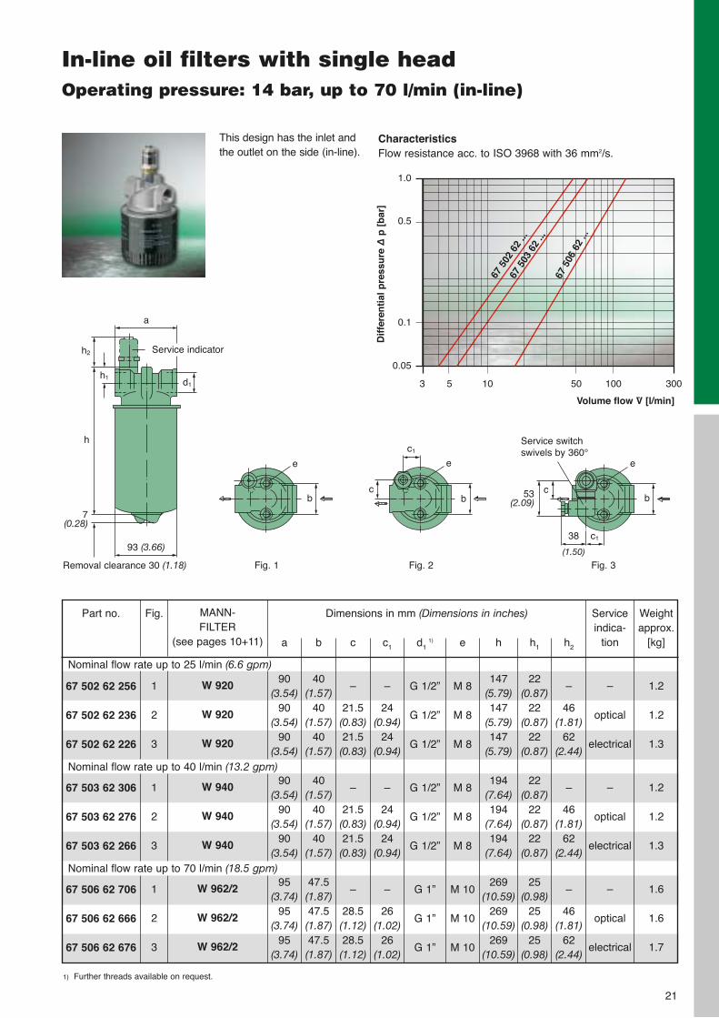
In-line oil filters with single headOperating pressure: 14 bar, up to 70 l/min (in-line)
Fig. 1
a
93 (3.66)
h
d1
h2
h1
7(0.28)
Removal clearance 30 (1.18)
b
e e
bc
c1
Fig. 2 Fig. 3
c138
(1.50)
53(2.09)
cb
e
Service switch swivels by 360°
1) Further threads available on request.
67 502 62 256
67 502 62 236
67 502 62 226
67 503 62 306
67 503 62 276
67 503 62 266
67 506 62 706
67 506 62 666
67 506 62 676
Part no. Dimensions in mm (Dimensions in inches)
a
90(3.54)
90(3.54)
90(3.54)
90(3.54)
90(3.54)
90(3.54)
95(3.74)
95(3.74)
95(3.74)
b
40(1.57)
40(1.57)
40(1.57)
40(1.57)
40(1.57)
40(1.57)
47.5(1.87)47.5(1.87)47.5(1.87)
c
–
21.5(0.83)21.5(0.83)
–
21.5(0.83)21.5(0.83)
–
28.5(1.12)28.5(1.12)
c1
–
24(0.94)
24(0.94)
–
24(0.94)
24(0.94)
–
26(1.02)
26(1.02)
h2
–
46(1.81)
62(2.44)
–
46(1.81)
62(2.44)
–
46(1.81)
62(2.44)
h1
22(0.87)
22(0.87)
22(0.87)
22(0.87)
22(0.87)
22(0.87)
25(0.98)
25(0.98)
25(0.98)
d1 1)
G 1/2”
G 1/2”
G 1/2”
G 1/2”
G 1/2”
G 1/2”
G 1”
G 1”
G 1”
h
147(5.79)147
(5.79)147
(5.79)
194(7.64)194
(7.64)194
(7.64)
269(10.59)
269(10.59)
269(10.59)
e
M 8
M 8
M 8
M 8
M 8
M 8
M 10
M 10
M 10
Weightapprox.
[kg]
1.2
1.2
1.3
1.2
1.2
1.3
1.6
1.6
1.7
Fig.
1
2
3
1
2
3
1
2
3
MANN-FILTER
(see pages 10+11)
W 920
W 920
W 920
W 940
W 940
W 940
W 962/2
W 962/2
W 962/2
Nominal flow rate up to 25 l/min (6.6 gpm)
Nominal flow rate up to 40 l/min (13.2 gpm)
Nominal flow rate up to 70 l/min (18.5 gpm)
Serviceindica-
tion
–
optical
electrical
–
optical
electrical
–
optical
electrical
Service indicator
21
Volume flow V̇ [l/min]
Dif
fere
nti
al p
ress
ure
∆p
[b
ar]
1.0
0.5
0.1
0.05
3 5 10 50 100 300
67 5
02 6
2 ...
67 5
03 6
2 ...
67 5
06 6
2 ...
CharacteristicsFlow resistance acc. to ISO 3968 with 36 mm2/s.
This design has the inlet andthe outlet on the side (in-line).
22
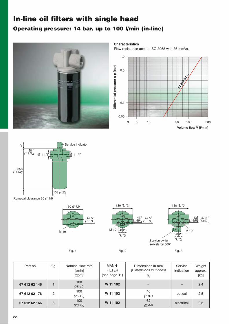
In-line oil filters with single headOperating pressure: 14 bar, up to 100 l/min (in-line)
67 612 62 146
67 612 62 176
67 612 62 166
Part no. Dimensions in mm (Dimensions in inches)
h2
–
46(1.81)
62(2.44)
Weightapprox.
[kg]
2.4
2.5
2.5
Fig.
1
2
3
MANN-FILTER
(see page 11)
W 11 102
W 11 102
W 11 102
Service indication
–
optical
electrical
Nominal flow rate[l/min][gpm]
100(26.42)
100(26.42)
100(26.42)
108 (4.25)
h2
Removal clearance 30 (1.18)
Service indicator
356(14.02)
50(1.97) G 1 1/4” G 1 1/4”
Fig. 1
47.5(1.87)
130 (5.12)
Fig. 2 Fig. 3
Service switch swivels by 360°
M 10
130 (5.12)
M 10
47.5(1.87)
43(1.69)
28 2828 28
M 10
130 (5.12)
47.5(1.87)
43(1.69)
(1.10)(1.10)
Volume flow V̇ [l/min]
Dif
fere
nti
al p
ress
ure
∆p
[b
ar]
1.0
0.5
0.1
0.05
3 5 10 50 100 300
67 6
12 6
2 ...
CharacteristicsFlow resistance acc. to ISO 3968 with 36 mm2/s.
23
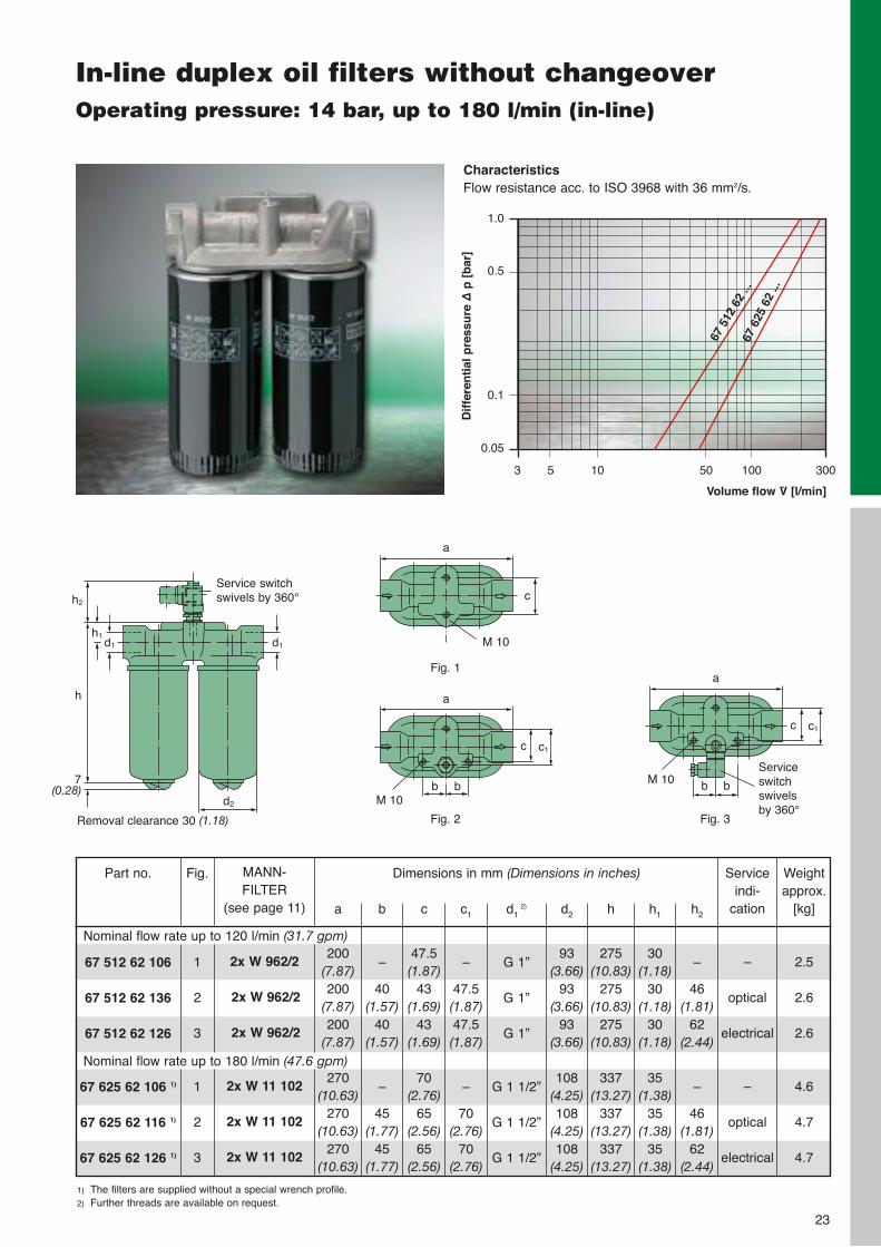
In-line duplex oil filters without changeoverOperating pressure: 14 bar, up to 180 l/min (in-line)
1) The filters are supplied without a special wrench profile.2) Further threads are available on request.
67 512 62 106
67 512 62 136
67 512 62 126
67 625 62 106 1)
67 625 62 116 1)
67 625 62 126 1)
Part no. Dimensions in mm (Dimensions in inches)
a
200(7.87)200
(7.87)200
(7.87)
270(10.63)
270(10.63)
270(10.63)
b
–
40(1.57)
40(1.57)
–
45(1.77)
45(1.77)
c
47.5(1.87)
43(1.69)
43(1.69)
70(2.76)
65(2.56)
65(2.56)
c1
–
47.5(1.87)47.5(1.87)
–
70(2.76)
70(2.76)
h2
–
46(1.81)
62(2.44)
–
46(1.81)
62(2.44)
h1
30(1.18)
30(1.18)
30(1.18)
35(1.38)
35(1.38)
35(1.38)
d1 2)
G 1”
G 1”
G 1”
G 1 1/2”
G 1 1/2”
G 1 1/2”
h
275(10.83)
275(10.83)
275(10.83)
337(13.27)
337(13.27)
337(13.27)
d2
93(3.66)
93(3.66)
93(3.66)
108(4.25)108
(4.25)108
(4.25)
Weightapprox.
[kg]
2.5
2.6
2.6
4.6
4.7
4.7
Fig.
1
2
3
1
2
3
MANN-FILTER
(see page 11)
2x W 962/2
2x W 962/2
2x W 962/2
2x W 11 102
2x W 11 102
2x W 11 102
Nominal flow rate up to 120 l/min (31.7 gpm)
Nominal flow rate up to 180 l/min (47.6 gpm)
Service indi-
cation
–
optical
electrical
–
optical
electrical
h2
Removal clearance 30 (1.18)
Service switch swivels by 360°
7(0.28)
h1d1d1
d2
h
a
c
M 10
Fig. 1
a
c
M 10
Fig. 2
c1
b b
a
c
M 10
Fig. 3
c1
b b
Serviceswitch swivels by 360°
Volume flow V̇ [l/min]
Dif
fere
nti
al p
ress
ure
∆p
[b
ar]
1.0
0.5
0.1
0.05
3 5 10 50 100 300
67 5
12 6
2 ...
67 6
25 6
2 ...
CharacteristicsFlow resistance acc. to ISO 3968 with 36 mm2/s.
24
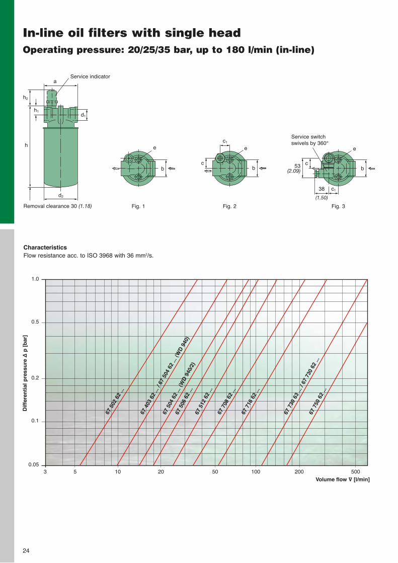
In-line oil filters with single headOperating pressure: 20/25/35 bar, up to 180 l/min (in-line)
CharacteristicsFlow resistance acc. to ISO 3968 with 36 mm2/s.
Fig. 1
b
e
Fig. 2 Fig. 3
Service switch swivels by 360°c1
38
(1.50)
c1
b
e
cb
e
c53(2.09)
h2
Removal clearance 30 (1.18)
Service indicator
h
a
d2
h1d1
Dif
fere
nti
al p
ress
ure
∆p
[b
ar]
Volume flow V̇ [l/min]3 5 10 20 50 100 200 500
1.0
0.5
0.2
0.1
0.05
67 7
08 6
2 ...
67 7
16 6
2 ...
67 7
30 6
3 ...
/ 67
730
62
...67
750
62
...
67 5
12 6
2 ...
67 5
06 6
2 ...
67 5
04 6
2 ...
(WD
940
/2)
67 4
03 6
2 ...
/ 67
504
62
... (W
D 9
40)
67 5
02 6
2 ...
25
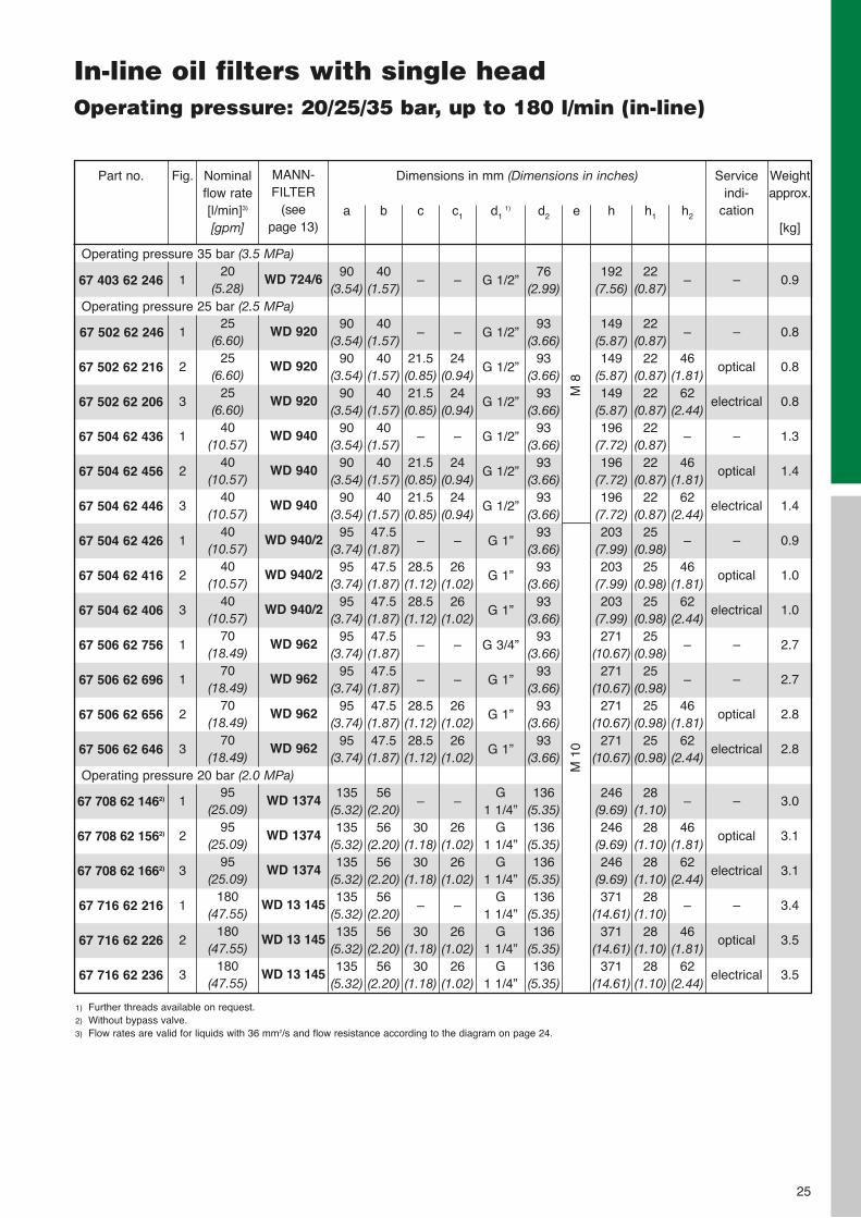
In-line oil filters with single headOperating pressure: 20/25/35 bar, up to 180 l/min (in-line)
1) Further threads available on request.2) Without bypass valve.3) Flow rates are valid for liquids with 36 mm2/s and flow resistance according to the diagram on page 24.
67 403 62 246
67 502 62 246
67 502 62 216
67 502 62 206
67 504 62 436
67 504 62 456
67 504 62 446
67 504 62 426
67 504 62 416
67 504 62 406
67 506 62 756
67 506 62 696
67 506 62 656
67 506 62 646
67 708 62 1462)
67 708 62 1562)
67 708 62 1662)
67 716 62 216
67 716 62 226
67 716 62 236
Part no. Dimensions in mm (Dimensions in inches)
a
90(3.54)
90(3.54)
90(3.54)
90(3.54)
90(3.54)
90(3.54)
90(3.54)
95(3.74)
95(3.74)
95(3.74)
95(3.74)
95(3.74)
95(3.74)
95(3.74)
135(5.32)135
(5.32)135
(5.32)135
(5.32)135
(5.32)135
(5.32)
b
40(1.57)
40(1.57)
40(1.57)
40(1.57)
40(1.57)
40(1.57)
40(1.57)47.5(1.87)47.5(1.87)47.5(1.87)47.5(1.87)47.5(1.87)47.5(1.87)47.5(1.87)
56(2.20)
56(2.20)
56(2.20)
56(2.20)
56(2.20)
56(2.20)
c
–
–
21.5(0.85)21.5(0.85)
–
21.5(0.85)21.5(0.85)
–
28.5(1.12)28.5(1.12)
–
–
28.5(1.12)28.5(1.12)
–
30(1.18)
30(1.18)
–
30(1.18)
30(1.18)
c1
–
–
24(0.94)
24(0.94)
–
24(0.94)
24(0.94)
–
26(1.02)
26(1.02)
–
–
26(1.02)
26(1.02)
–
26(1.02)
26(1.02)
–
26(1.02)
26(1.02)
h2
–
–
46(1.81)
62(2.44)
–
46(1.81)
62(2.44)
–
46(1.81)
62(2.44)
–
–
46(1.81)
62(2.44)
–
46(1.81)
62(2.44)
–
46(1.81)
62(2.44)
h1
22(0.87)
22(0.87)
22(0.87)
22(0.87)
22(0.87)
22(0.87)
22(0.87)
25(0.98)
25(0.98)
25(0.98)
25(0.98)
25(0.98)
25(0.98)
25(0.98)
28(1.10)
28(1.10)
28(1.10)
28(1.10)
28(1.10)
28(1.10)
d1 1)
G 1/2”
G 1/2”
G 1/2”
G 1/2”
G 1/2”
G 1/2”
G 1/2”
G 1”
G 1”
G 1”
G 3/4”
G 1”
G 1”
G 1”
G 1 1/4”
G 1 1/4”
G 1 1/4”
G 1 1/4”
G 1 1/4”
G 1 1/4”
h
192(7.56)
149(5.87)149
(5.87)149
(5.87)196
(7.72)196
(7.72)196
(7.72)203
(7.99)203
(7.99)203
(7.99)271
(10.67)271
(10.67)271
(10.67)271
(10.67)
246(9.69)246
(9.69)246
(9.69)371
(14.61)371
(14.61)371
(14.61)
d2
76(2.99)
93(3.66)
93(3.66)
93(3.66)
93(3.66)
93(3.66)
93(3.66)
93(3.66)
93(3.66)
93(3.66)
93(3.66)
93(3.66)
93(3.66)
93(3.66)
136(5.35)136
(5.35)136
(5.35)136
(5.35)136
(5.35)136
(5.35)
Weightapprox.
[kg]
0.9
0.8
0.8
0.8
1.3
1.4
1.4
0.9
1.0
1.0
2.7
2.7
2.8
2.8
3.0
3.1
3.1
3.4
3.5
3.5
Fig.
1
1
2
3
1
2
3
1
2
3
1
1
2
3
1
2
3
1
2
3
MANN-FILTER
(see page 13)
WD 724/6
WD 920
WD 920
WD 920
WD 940
WD 940
WD 940
WD 940/2
WD 940/2
WD 940/2
WD 962
WD 962
WD 962
WD 962
WD 1374
WD 1374
WD 1374
WD 13 145
WD 13 145
WD 13 145
Operating pressure 35 bar (3.5 MPa)
Operating pressure 25 bar (2.5 MPa)
Serviceindi-
cation
–
–
optical
electrical
–
optical
electrical
–
optical
electrical
–
–
optical
electrical
–
optical
electrical
–
optical
electrical
Nominalflow rate[l/min]3)
[gpm]
20(5.28)
25(6.60)
25(6.60)
25(6.60)
40(10.57)
40(10.57)
40(10.57)
40(10.57)
40(10.57)
40(10.57)
70(18.49)
70(18.49)
70(18.49)
70(18.49)
95(25.09)
95(25.09)
95(25.09)
180(47.55)
180(47.55)
180(47.55)
Operating pressure 20 bar (2.0 MPa)
e
M 8
M 1
0
26
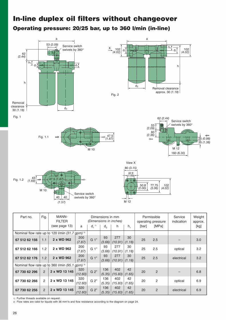
In-line duplex oil filters without changeoverOperating pressure: 20/25 bar, up to 360 l/min (in-line)
1) Further threads available on request.2) Flow rates are valid for liquids with 36 mm2/s and flow resistance according to the diagram on page 24.
67 512 62 156
67 512 62 166
67 512 62 176
67 730 62 296
67 730 62 266
67 730 62 256
Part no. Dimensions in mm (Dimensions in inches)
a
200(7.87)200
(7.87)200
(7.87)
320(12.60)
320(12.60)
320(12.60)
h1
30(1.18)
30(1.18)
30(1.18)
42(1.65)
42(1.65)
42(1.65)
d1 1)
G 1”
G 1”
G 1”
G 2”
G 2”
G 2”
h
277(10.91)
277(10.91)
277(10.91)
402(15.83)
402(15.83)
402(15.83)
d2
93(3.66)
93(3.66)
93(3.66)
136(5.35)136
(5.35)136
(5.35)
Weightapprox.
[kg]
3.0
3.2
3.2
6.8
6.9
6.9
Fig.
1.1
1.2
1.2
2
2
2
MANN-FILTER
(see page 13)
2 x WD 962
2 x WD 962
2 x WD 962
2 x WD 13 145
2 x WD 13 145
2 x WD 13 145
Nominal flow rate up to 120 l/min (31.7 gpm) 2)
Nominal flow rate up to 360 l/min (95.1 gpm) 2)
Service indication
–
optical
electrical
–
optical
electrical
Permissible operating pressure
[bar] [MPa]
25 2.5
25 2.5
25 2.5
20 2
20 2
20 2
Removalclearance30 (1.18)
h
a
d2
h1d1
Service switch swivels by 360°
62(2.44)
d1
53 (2.09)
a
d2Removal clearance
approx. 30 (1.18)
h
d1 d1102
(4.02)X h1
47.5(1.87)
M 10
M 12
Service switch swivels by 360°40 40
43(1.69)
M 10
Service switch swivels by 360°
62 (2.44)
160 (6.30)
80 (3.15)
53(2.09)
25 (0.98)
60(2.36)
M 12
35 (1.38)
42.9 (1.69)
102(4.02)
77.75(3.06)
50.8(2.00)
View X
Fig. 1
Fig. 2
Fig. 1.1
Fig. 1.2
102(4.02)
(1.57)
47.5 (1.87)
27
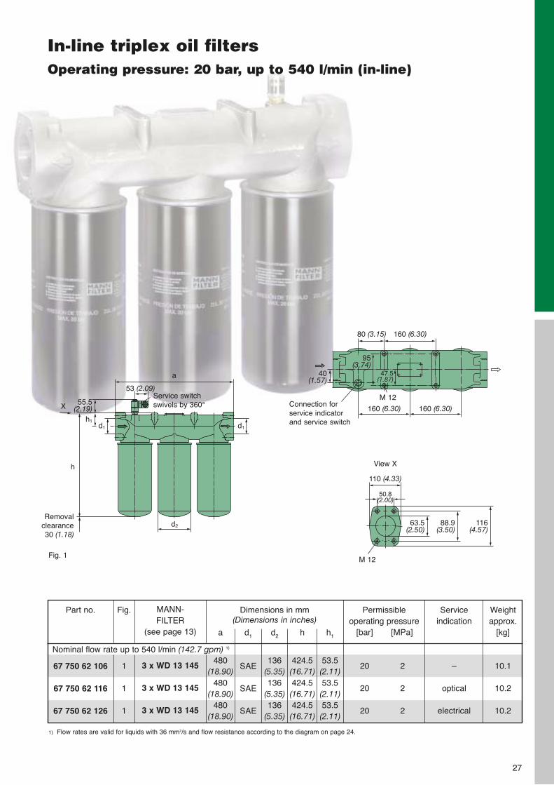
In-line triplex oil filtersOperating pressure: 20 bar, up to 540 l/min (in-line)
Service switch swivels by 360°
a
53 (2.09)
Removalclearance30 (1.18)
d2
h
d1 d1
55.5(2.19)
h1
X
Fig. 1
Connection for service indicator and service switch
80 (3.15)
160 (6.30)
M 12
160 (6.30)
160 (6.30)
40(1.57)
47.5(1.87)
95(3.74)
110 (4.33)
View X
50.8(2.00)
M 12
116(4.57)
88.9(3.50)
63.5(2.50)
1) Flow rates are valid for liquids with 36 mm2/s and flow resistance according to the diagram on page 24.
67 750 62 106
67 750 62 116
67 750 62 126
Part no. Dimensions in mm (Dimensions in inches)
a
480(18.90)
480(18.90)
480(18.90)
d1
SAE
SAE
SAE
d2
136(5.35)136
(5.35)136
(5.35)
h
424.5(16.71)424.5(16.71)424.5(16.71)
h1
53.5(2.11)53.5(2.11)53.5(2.11)
Weightapprox.
[kg]
10.1
10.2
10.2
Fig.
1
1
1
MANN-FILTER
(see page 13)
3 x WD 13 145
3 x WD 13 145
3 x WD 13 145
Nominal flow rate up to 540 l/min (142.7 gpm) 1)
Service indication
–
optical
electrical
Permissible operating pressure
[bar] [MPa]
20 2
20 2
20 2
28
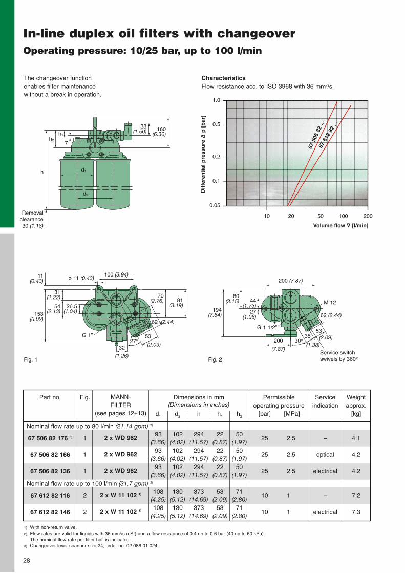
In-line duplex oil filters with changeoverOperating pressure: 10/25 bar, up to 100 l/min
h2
Removalclearance30 (1.18)
h
h1
The changeover functionenables filter maintenancewithout a break in operation.
CharacteristicsFlow resistance acc. to ISO 3968 with 36 mm2/s.
Fig. 1
7
38(1.50) 160
(6.30)
d1
d2
Fig. 2
100 (3.94)11(0.43)
153(6.02)
31(1.22)
54(2.13)
26.5(1.04)
ø 11 (0.43)
70(2.76) 81
(3.19)
62 (2.44)
53
(2.09)32
(1.26)
27°G 1”
Service switch swivels by 360°
62 (2.44)
53(2.09)200
(7.87)
30°35
(1.38)
M 12
200 (7.87)
194(7.64)
80(3.15) 44
(1.73)
G 1 1/2”
27(1.06)
1) With non-return valve.2) Flow rates are valid for liquids with 36 mm2/s (cSt) and a flow resistance of 0.4 up to 0.6 bar (40 up to 60 kPa).
The nominal flow rate per filter half is indicated.3) Changeover lever spanner size 24, order no. 02 086 01 024.
67 506 82 176 3)
67 506 82 166
67 506 82 136
67 612 82 116
67 612 82 146
Part no. Dimensions in mm (Dimensions in inches)
d1
93(3.66)
93(3.66)
93(3.66)
108(4.25)108
(4.25)
h2
50(1.97)
50(1.97)
50(1.97)
71(2.80)
71(2.80)
d2
102(4.02)102
(4.02)102
(4.02)
130(5.12)130
(5.12)
h1
22(0.87)
22(0.87)
22(0.87)
53(2.09)
53(2.09)
h
294(11.57)
294(11.57)
294(11.57)
373(14.69)
373(14.69)
Weightapprox.
[kg]
4.1
4.2
4.2
7.2
7.3
Fig.
1
1
1
2
2
MANN-FILTER
(see pages 12+13)
2 x WD 962
2 x WD 962
2 x WD 962
2 x W 11 102 1)
2 x W 11 102 1)
Nominal flow rate up to 80 l/min (21.14 gpm) 2)
Nominal flow rate up to 100 l/min (31.7 gpm) 2)
Service indication
–
optical
electrical
–
electrical
Permissible operating pressure
[bar] [MPa]
25 2.5
25 2.5
25 2.5
10 1
10 1
Volume flow V̇ [l/min]
Dif
fere
nti
al p
ress
ure
∆p
[b
ar]
1.0
0.5
0.2
0.1
0.05
10 20 50 100 200
67 5
06 8
2 ...
67 6
12 8
2 ...
29
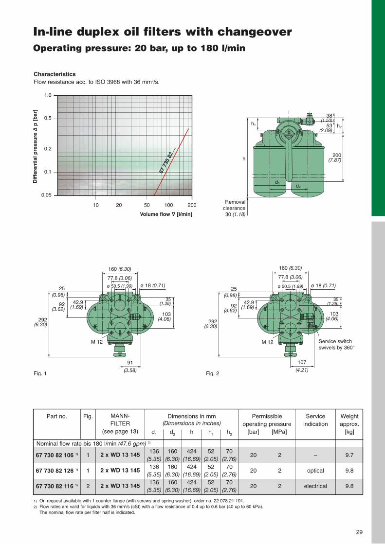
In-line duplex oil filters with changeoverOperating pressure: 20 bar, up to 180 l/min
ZUR REINIGUNG DREHEN
1) On request available with 1 counter flange (with screws and spring washer), order no. 22 078 21 101.2) Flow rates are valid for liquids with 36 mm2/s (cSt) with a flow resistance of 0.4 up to 0.6 bar (40 up to 60 kPa).
The nominal flow rate per filter half is indicated.
67 730 82 106 1)
67 730 82 126 1)
67 730 82 116 1)
Part no. Dimensions in mm (Dimensions in inches)
d1
136(5.35)136
(5.35)136
(5.35)
d2
160(6.30)160
(6.30)160
(6.30)
h
424(16.69)
424(16.69)
424(16.69)
h1
52(2.05)
52(2.05)
52(2.05)
h2
70(2.76)
70(2.76)
70(2.76)
Weightapprox.
[kg]
9.7
9.8
9.8
Fig.
1
1
2
MANN-FILTER
(see page 13)
2 x WD 13 145
2 x WD 13 145
2 x WD 13 145
Nominal flow rate bis 180 l/min (47.6 gpm) 2)
Service indication
–
optical
electrical
Permissible operating pressure
[bar] [MPa]
20 2
20 2
20 2
160 (6.30)
292(6.30)
Fig. 1 Fig. 2
77.8 (3.06)ø 18 (0.71)
92(3.62)
25(0.98)
42.9(1.69)
91
(3.58)
M 12
103(4.06)
35(1.38)
160 (6.30)
292(6.30)
77.8 (3.06)
ø 18 (0.71)
92(3.62)
25(0.98)
42.9(1.69)
107
(4.21)
M 12
103(4.06)
35(1.38)
Service switch swivels by 360°
h1
Removalclearance30 (1.18)
h
d2d1
h253(2.09)
38(1.50)
200(7.87)
ø 50.5 (1.99) ø 50.5 (1.99)
CharacteristicsFlow resistance acc. to ISO 3968 with 36 mm2/s.
Volume flow V̇ [l/min]
Dif
fere
nti
al p
ress
ure
∆p
[b
ar]
1.0
0.5
0.2
0.1
0.05
10 20 50 100 200
67 7
30 8
2 ...
30
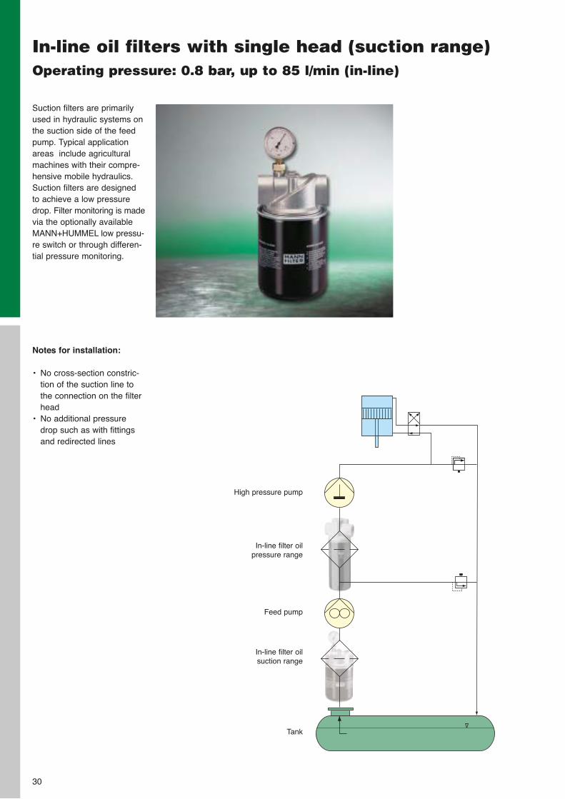
In-line oil filters with single head (suction range)Operating pressure: 0.8 bar, up to 85 l/min (in-line)
Suction filters are primarilyused in hydraulic systems onthe suction side of the feedpump. Typical applicationareas include agriculturalmachines with their compre-hensive mobile hydraulics.Suction filters are designedto achieve a low pressuredrop. Filter monitoring is madevia the optionally availableMANN+HUMMEL low pressu-re switch or through differen-tial pressure monitoring.
Notes for installation:
• No cross-section constric-tion of the suction line tothe connection on the filterhead
• No additional pressuredrop such as with fittingsand redirected lines
High pressure pump
In-line filter oil pressure range
Feed pump
In-line filter oil suction range
Tank
31
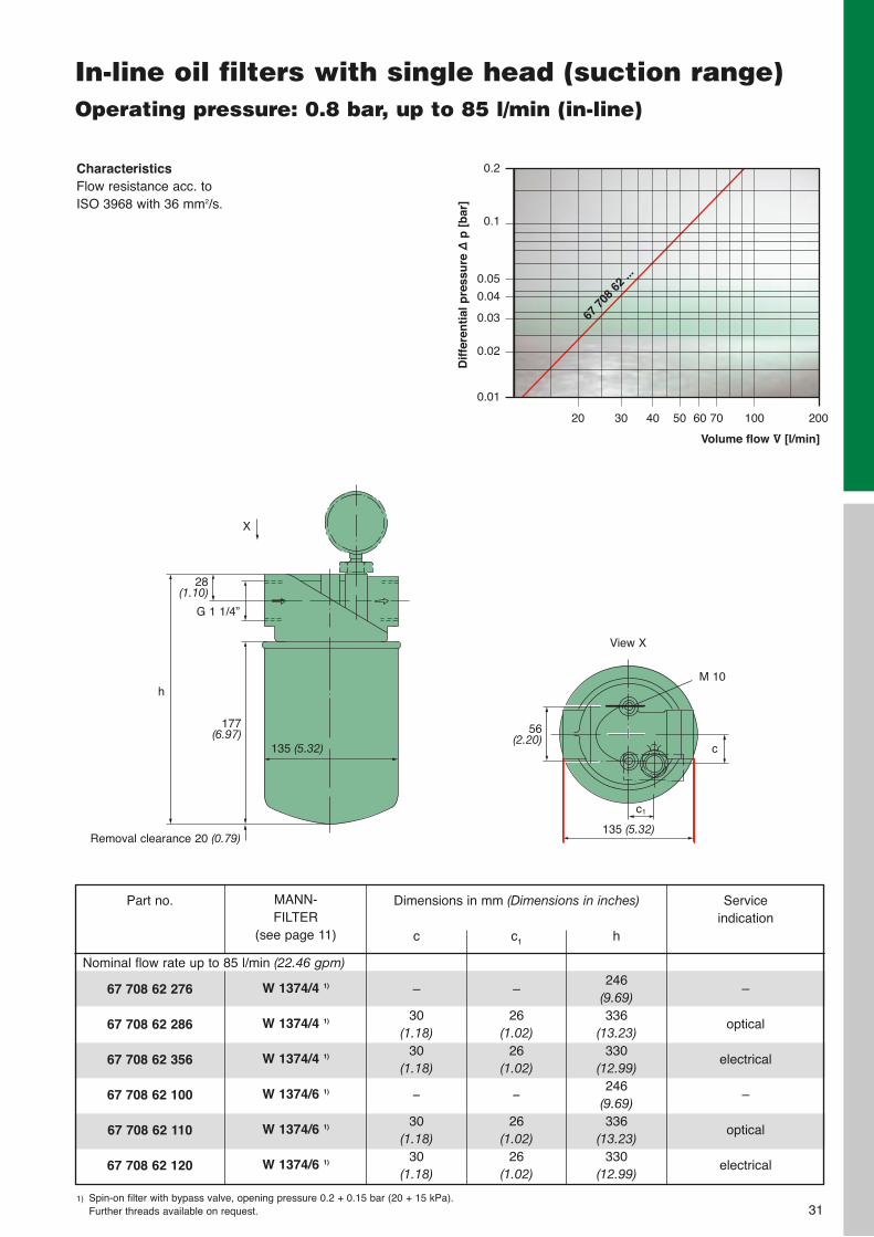
In-line oil filters with single head (suction range)Operating pressure: 0.8 bar, up to 85 l/min (in-line)
CharacteristicsFlow resistance acc. to ISO 3968 with 36 mm2/s.
Removal clearance 20 (0.79)
h
135 (5.32)
X
28(1.10)
177(6.97)
c1
G 1 1/4”
c
56(2.20)
135 (5.32)
View X
M 10
1) Spin-on filter with bypass valve, opening pressure 0.2 + 0.15 bar (20 + 15 kPa).Further threads available on request.
67 708 62 276
67 708 62 286
67 708 62 356
67 708 62 100
67 708 62 110
67 708 62 120
Part no. Dimensions in mm (Dimensions in inches)
c
–
30(1.18)
30(1.18)
–
30(1.18)
30(1.18)
c1
–
26(1.02)
26(1.02)
–
26(1.02)
26(1.02)
h
246(9.69)336
(13.23)330
(12.99)246
(9.69)336
(13.23)330
(12.99)
MANN-FILTER
(see page 11)
W 1374/4 1)
W 1374/4 1)
W 1374/4 1)
W 1374/6 1)
W 1374/6 1)
W 1374/6 1)
Nominal flow rate up to 85 l/min (22.46 gpm)
Service indication
–
optical
electrical
–
optical
electrical
Volume flow V̇ [l/min]
Dif
fere
nti
al p
ress
ure
∆p
[b
ar]
0.2
0.1
0.05
0.04
0.03
0.02
0.01
20 30 40 50 60 70 100 200
67 7
08 6
2 ...

32
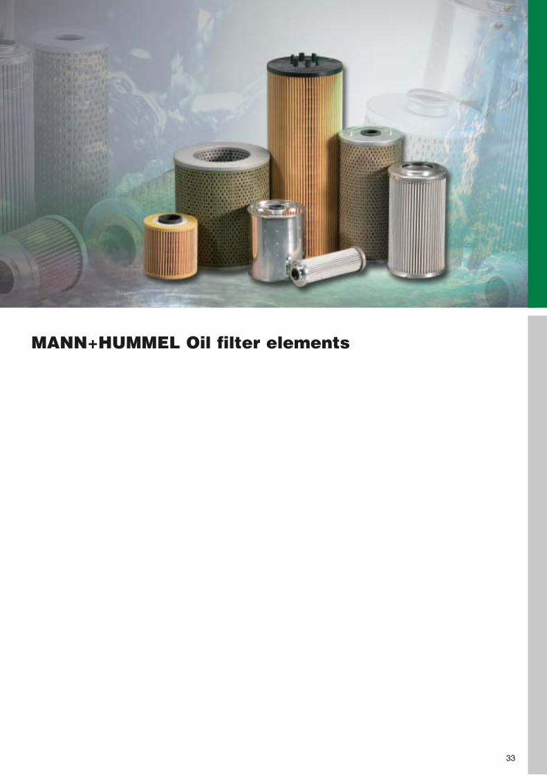
MANN+HUMMEL Oil filter elements
33
34
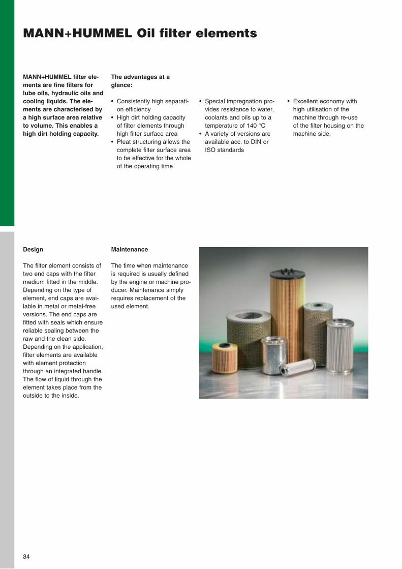
MANN+HUMMEL Oil filter elements
The advantages at a glance:
• Consistently high separati-on efficiency
• High dirt holding capacityof filter elements throughhigh filter surface area
• Pleat structuring allows thecomplete filter surface areato be effective for the wholeof the operating time
MANN+HUMMEL filter ele-ments are fine filters forlube oils, hydraulic oils andcooling liquids. The ele-ments are characterised bya high surface area relativeto volume. This enables ahigh dirt holding capacity.
• Special impregnation pro-vides resistance to water,coolants and oils up to atemperature of 140 °C
• A variety of versions areavailable acc. to DIN orISO standards
• Excellent economy withhigh utilisation of themachine through re-use of the filter housing on themachine side.
Design
The filter element consists oftwo end caps with the filtermedium fitted in the middle.Depending on the type ofelement, end caps are avai-lable in metal or metal-freeversions. The end caps arefitted with seals which ensurereliable sealing between theraw and the clean side.Depending on the application,filter elements are availablewith element protectionthrough an integrated handle.The flow of liquid through theelement takes place from theoutside to the inside.
Maintenance
The time when maintenanceis required is usually definedby the engine or machine pro-ducer. Maintenance simplyrequires replacement of theused element.
H 31/1
H 31/2
H 42
H 53
H 53/3
H 68/1
H 601
H 601/4
H 614/3
H 616/1
H 617 N
H 715/1 X
MANN-FILTER
Dimensions in mm (Dimensions in inches)
d1
30.5(1.20)
26(1.02)27.5(1.08)
40(1.57)
40(1.57)
59(2.32)
59(2.32)
60(2.36)
59(2.32)
59(2.32)
59(2.32)
68(2.68)
d2
8(0.32)
8(0.32)
10(0.39)12.8(0.50)12.8(0.50)
32(1.26)
18(0.71)
18(0.71)28.3(1.11)
32(1.26)28.2(1.11)
20(0.79)
h
26(1.02)
19(0.75)
51(2.01)
64(2.52)
64(2.52)103
(4.06)101
(3.98)101
(3.98)200
(7.87)189
(7.44)101
(3.98)109
(4.29)
Type
E
A
A
A
A
E
A
A
E
E
A
B
Nominal flow rate
[l/min][gpm]
0.5 (0.1)0.5(0.1) 1.5(0.4)
5(1.3)
5(1.3)10
(2.6)17
(4.5)17
(4.5)18
(4.8)20
(5.3)21
(5.5)18
(4.8)
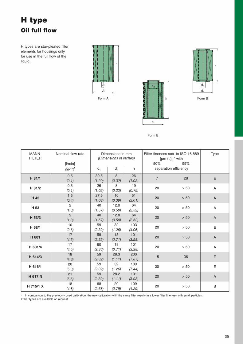
H types are star-pleated filterelements for housings onlyfor use in the full flow of theliquid.
H typeOil full flow
50%
7
20
20
20
20
20
20
20
15
20
20
20
99%
28
> 50
> 50
> 50
> 50
> 50
> 50
> 50
36
> 50
> 50
> 50
Filter fineness acc. to ISO 16 889[µm (c)] * with
separation efficiency
35
Form A Form B
h
d2
d1
h
d2
d1
Form E
h
d1
d2
* In comparison to the previously used calibration, the new calibration with the same filter results in a lower filter fineness with small particles.Other types are available on request.
36
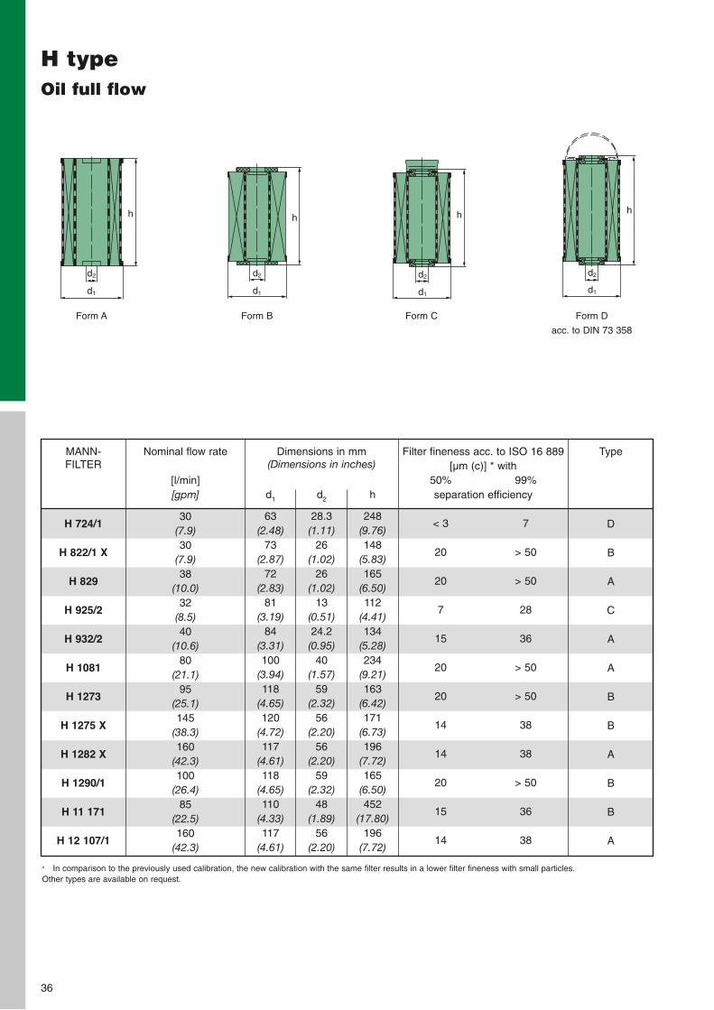
H typeOil full flow
H 724/1
H 822/1 X
H 829
H 925/2
H 932/2
H 1081
H 1273
H 1275 X
H 1282 X
H 1290/1
H 11 171
H 12 107/1
MANN-FILTER
Dimensions in mm (Dimensions in inches)
d1
63(2.48)
73(2.87)
72(2.83)
81(3.19)
84(3.31)100
(3.94)118
(4.65)120
(4.72)117
(4.61)118
(4.65)110
(4.33)117
(4.61)
d2
28.3(1.11)
26(1.02)
26(1.02)
13(0.51)24.2(0.95)
40(1.57)
59(2.32)
56(2.20)
56(2.20)
59(2.32)
48(1.89)
56(2.20)
h
248(9.76)148
(5.83)165
(6.50)112
(4.41)134
(5.28)234
(9.21)163
(6.42)171
(6.73)196
(7.72)165
(6.50)452
(17.80)196
(7.72)
Type
D
B
A
C
A
A
B
B
A
B
B
A
Nominal flow rate
[l/min][gpm]
30(7.9)30
(7.9)38
(10.0)32
(8.5)40
(10.6)80
(21.1)95
(25.1)145
(38.3)160
(42.3)100
(26.4)85
(22.5)160
(42.3)
50%
< 3
20
20
7
15
20
20
14
14
20
15
14
99%
7
> 50
> 50
28
36
> 50
> 50
38
38
> 50
36
38
Filter fineness acc. to ISO 16 889[µm (c)] * with
separation efficiency
Form A Form B Form C Form D
acc. to DIN 73 358
h
d2
d1
h
d2
d1
h
d2
d1
h
d2
d1
* In comparison to the previously used calibration, the new calibration with the same filter results in a lower filter fineness with small particles.Other types are available on request.
37
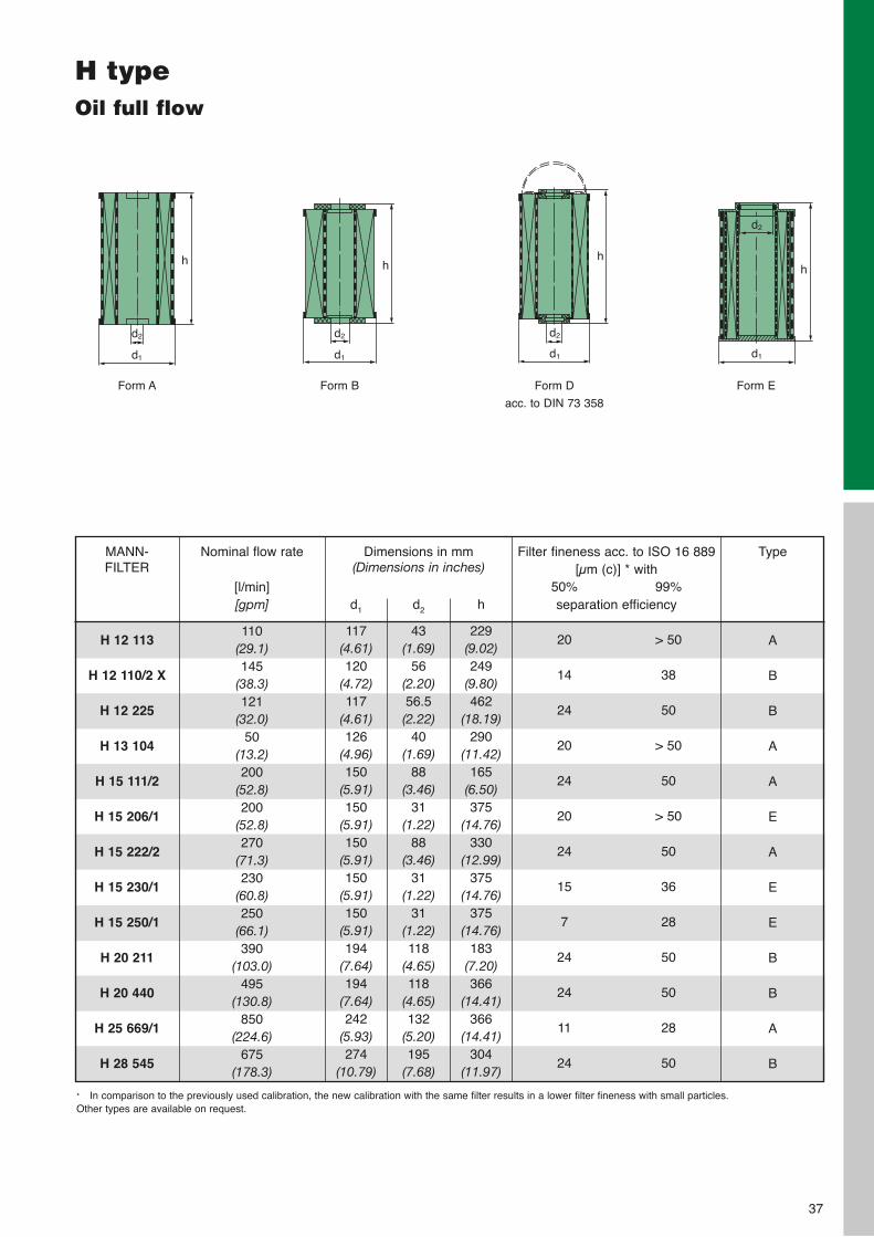
H typeOil full flow
H 12 113
H 12 110/2 X
H 12 225
H 13 104
H 15 111/2
H 15 206/1
H 15 222/2
H 15 230/1
H 15 250/1
H 20 211
H 20 440
H 25 669/1
H 28 545
MANN-FILTER
Dimensions in mm (Dimensions in inches)
d1
117(4.61)120
(4.72)117
(4.61)126
(4.96)150
(5.91)150
(5.91)150
(5.91)150
(5.91)150
(5.91)194
(7.64)194
(7.64)242
(5.93)274
(10.79)
d2
43(1.69)
56(2.20)56.5(2.22)
40(1.69)
88(3.46)
31(1.22)
88(3.46)
31(1.22)
31(1.22)118
(4.65)118
(4.65)132
(5.20)195
(7.68)
h
229(9.02)249
(9.80)462
(18.19)290
(11.42)165
(6.50)375
(14.76)330
(12.99)375
(14.76)375
(14.76)183
(7.20)366
(14.41)366
(14.41)304
(11.97)
Type
A
B
B
A
A
E
A
E
E
B
B
A
B
Nominal flow rate
[l/min][gpm]
110(29.1)145
(38.3)121
(32.0)50
(13.2)200
(52.8)200
(52.8)270
(71.3)230
(60.8)250
(66.1)390
(103.0)495
(130.8)850
(224.6)675
(178.3)
50%
20
14
24
20
24
20
24
15
7
24
24
11
24
99%
> 50
38
50
> 50
50
> 50
50
36
28
50
50
28
50
Filter fineness acc. to ISO 16 889[µm (c)] * with
separation efficiency
* In comparison to the previously used calibration, the new calibration with the same filter results in a lower filter fineness with small particles.Other types are available on request.
Form A Form B Form D
acc. to DIN 73 358
h
d2
d1
h
d2
d1
h
d2
d1
Form E
h
d1
d2
38
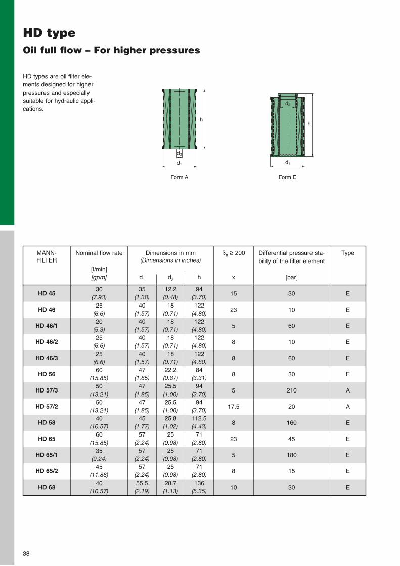
HD typeOil full flow – For higher pressures
HD types are oil filter ele-ments designed for higherpressures and especially suitable for hydraulic appli-cations.
HD 45
HD 46
HD 46/1
HD 46/2
HD 46/3
HD 56
HD 57/3
HD 57/2
HD 58
HD 65
HD 65/1
HD 65/2
HD 68
MANN-FILTER
Dimensions in mm (Dimensions in inches)
d1
35(1.38)
40(1.57)
40(1.57)
40(1.57)
40(1.57)
47(1.85)
47(1.85)
47(1.85)
45(1.77)
57(2.24)
57(2.24)
57(2.24)55.5(2.19)
d2
12.2(0.48)
18(0.71)
18(0.71)
18(0.71)
18(0.71)22.2(0.87)25.5(1.00)25.5(1.00)25.8(1.02)
25(0.98)
25(0.98)
25(0.98)28.7(1.13)
h
94(3.70)122
(4.80)122
(4.80)122
(4.80)122
(4.80)84
(3.31)94
(3.70)94
(3.70)112.5(4.43)
71(2.80)
71(2.80)
71(2.80)136
(5.35)
Type
E
E
E
E
E
E
A
A
E
E
E
E
E
Nominal flow rate
[l/min][gpm]
30(7.93)
25(6.6) 20
(5.3)25
(6.6)25
(6.6)60
(15.85)50
(13.21)50
(13.21)40
(10.57)60
(15.85)35
(9.24)45
(11.88)40
(10.57)
Differential pressure sta-bility of the filter element
[bar]
30
10
60
10
60
30
210
20
160
45
180
15
30
ßx ≥ 200
x
15
23
5
8
8
8
5
17.5
8
23
5
8
10
Form A
h
d2
d1
Form E
h
d1
d2
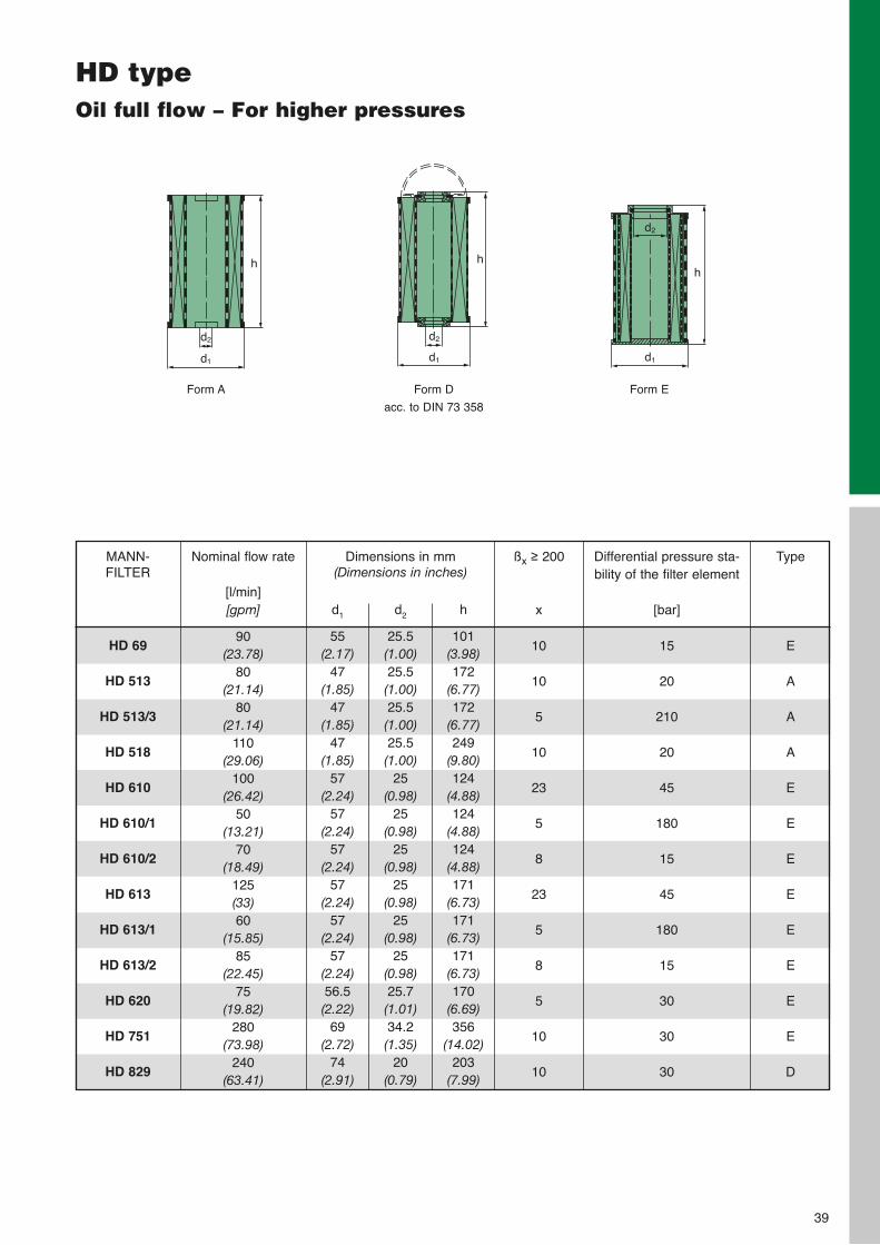
39
HD typeOil full flow – For higher pressures
HD 69
HD 513
HD 513/3
HD 518
HD 610
HD 610/1
HD 610/2
HD 613
HD 613/1
HD 613/2
HD 620
HD 751
HD 829
MANN-FILTER
Dimensions in mm (Dimensions in inches)
d1
55(2.17)
47(1.85)
47(1.85)
47(1.85)
57(2.24)
57(2.24)
57(2.24)
57(2.24)
57(2.24)
57(2.24)56.5(2.22)
69(2.72)
74(2.91)
d2
25.5(1.00)25.5(1.00)25.5(1.00)25.5(1.00)
25(0.98)
25(0.98)
25(0.98)
25(0.98)
25(0.98)
25(0.98)25.7(1.01)34.2(1.35)
20(0.79)
h
101(3.98)172
(6.77)172
(6.77)249
(9.80)124
(4.88)124
(4.88)124
(4.88)171
(6.73)171
(6.73)171
(6.73)170
(6.69)356
(14.02)203
(7.99)
Type
E
A
A
A
E
E
E
E
E
E
E
E
D
Nominal flow rate
[l/min][gpm]
90(23.78)
80(21.14)
80(21.14)
110(29.06)
100(26.42)
50(13.21)
70(18.49)
125(33)60
(15.85)85
(22.45)75
(19.82)280
(73.98)240
(63.41)
Differential pressure sta-bility of the filter element
[bar]
15
20
210
20
45
180
15
45
180
15
30
30
30
ßx ≥ 200
x
10
10
5
10
23
5
8
23
5
8
5
10
10
Form A Form D
acc. to DIN 73 358
h
d2
d1
h
d2
d1
Form E
h
d1
d2
40
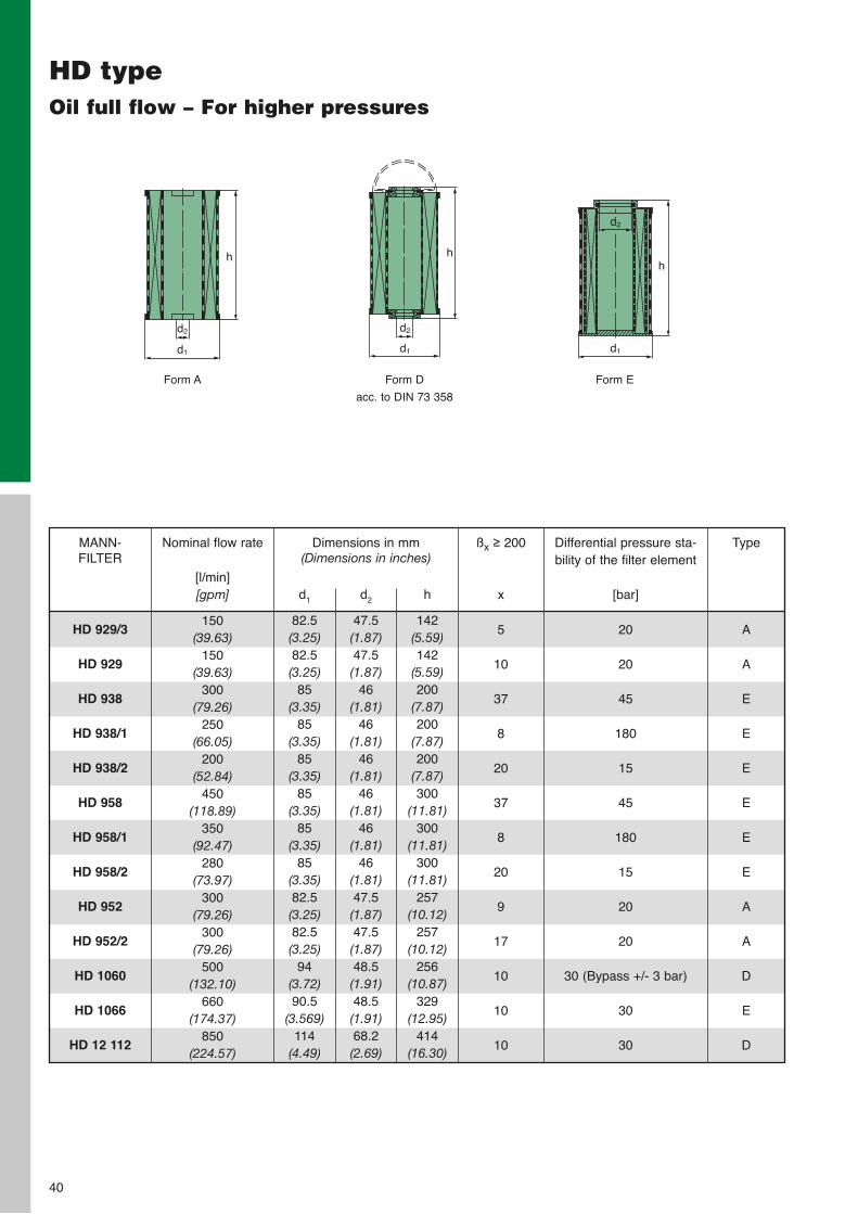
HD typeOil full flow – For higher pressures
HD 929/3
HD 929
HD 938
HD 938/1
HD 938/2
HD 958
HD 958/1
HD 958/2
HD 952
HD 952/2
HD 1060
HD 1066
HD 12 112
MANN-FILTER
Dimensions in mm (Dimensions in inches)
d1
82.5(3.25)82.5(3.25)
85(3.35)
85(3.35)
85(3.35)
85(3.35)
85(3.35)
85(3.35)82.5(3.25)82.5(3.25)
94(3.72)90.5
(3.569)114
(4.49)
d2
47.5(1.87)47.5(1.87)
46(1.81)
46(1.81)
46(1.81)
46(1.81)
46(1.81)
46(1.81)47.5(1.87)47.5(1.87)48.5(1.91)48.5(1.91)68.2(2.69)
h
142(5.59)142
(5.59)200
(7.87)200
(7.87)200
(7.87)300
(11.81)300
(11.81)300
(11.81)257
(10.12)257
(10.12)256
(10.87)329
(12.95)414
(16.30)
Type
A
A
E
E
E
E
E
E
A
A
D
E
D
Nominal flow rate
[l/min][gpm]
150(39.63)
150(39.63)
300(79.26)
250(66.05)
200(52.84)
450(118.89)
350(92.47)
280(73.97)
300(79.26)
300(79.26)
500(132.10)
660(174.37)
850(224.57)
Differential pressure sta-bility of the filter element
[bar]
20
20
45
180
15
45
180
15
20
20
30 (Bypass +/- 3 bar)
30
30
ßx ≥ 200
x
5
10
37
8
20
37
8
20
9
17
10
10
10
Form A Form D
acc. to DIN 73 358
h
d2
d1
h
d2
d1
Form E
h
d1
d2
41
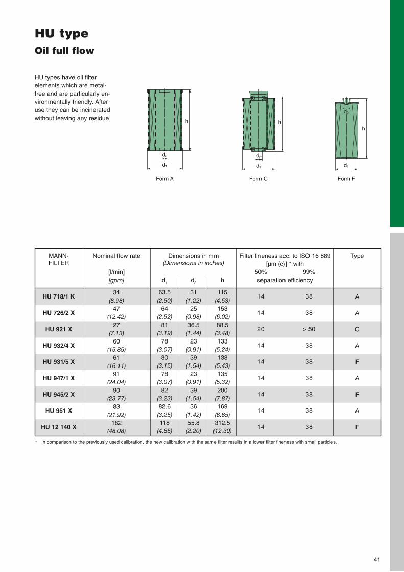
HU typeOil full flow
HU types have oil filter elements which are metal-free and are particularly en-vironmentally friendly. Afteruse they can be incineratedwithout leaving any residue
HU 718/1 K
HU 726/2 X
HU 921 X
HU 932/4 X
HU 931/5 X
HU 947/1 X
HU 945/2 X
HU 951 X
HU 12 140 X
MANN-FILTER
Dimensions in mm (Dimensions in inches)
d1
63.5(2.50)
64(2.52)
81(3.19)
78(3.07)
80(3.15)
78(3.07)
82(3.23)82.6(3.25)118
(4.65)
d2
31(1.22)
25(0.98)36.5(1.44)
23(0.91)
39(1.54)
23(0.91)
39(1.54)
36(1.42)55.8(2.20)
h
115(4.53)153
(6.02)88.5(3.48)133
(5.24)138
(5.43)135
(5.32)200
(7.87)169
(6.65)312.5(12.30)
Type
A
A
C
A
F
A
F
A
F
Nominal flow rate
[l/min][gpm]
34(8.98)
47(12.42)
27(7.13)
60(15.85)
61(16.11)
91(24.04)
90(23.77)
83(21.92)
182(48.08)
50%
14
14
20
14
14
14
14
14
14
99%
38
38
> 50
38
38
38
38
38
38
Filter fineness acc. to ISO 16 889[µm (c)] * with
separation efficiency
Form C Form F
h
d2
d1
h
d2
d1
Form A
h
d2
d1
* In comparison to the previously used calibration, the new calibration with the same filter results in a lower filter fineness with small particles.
42
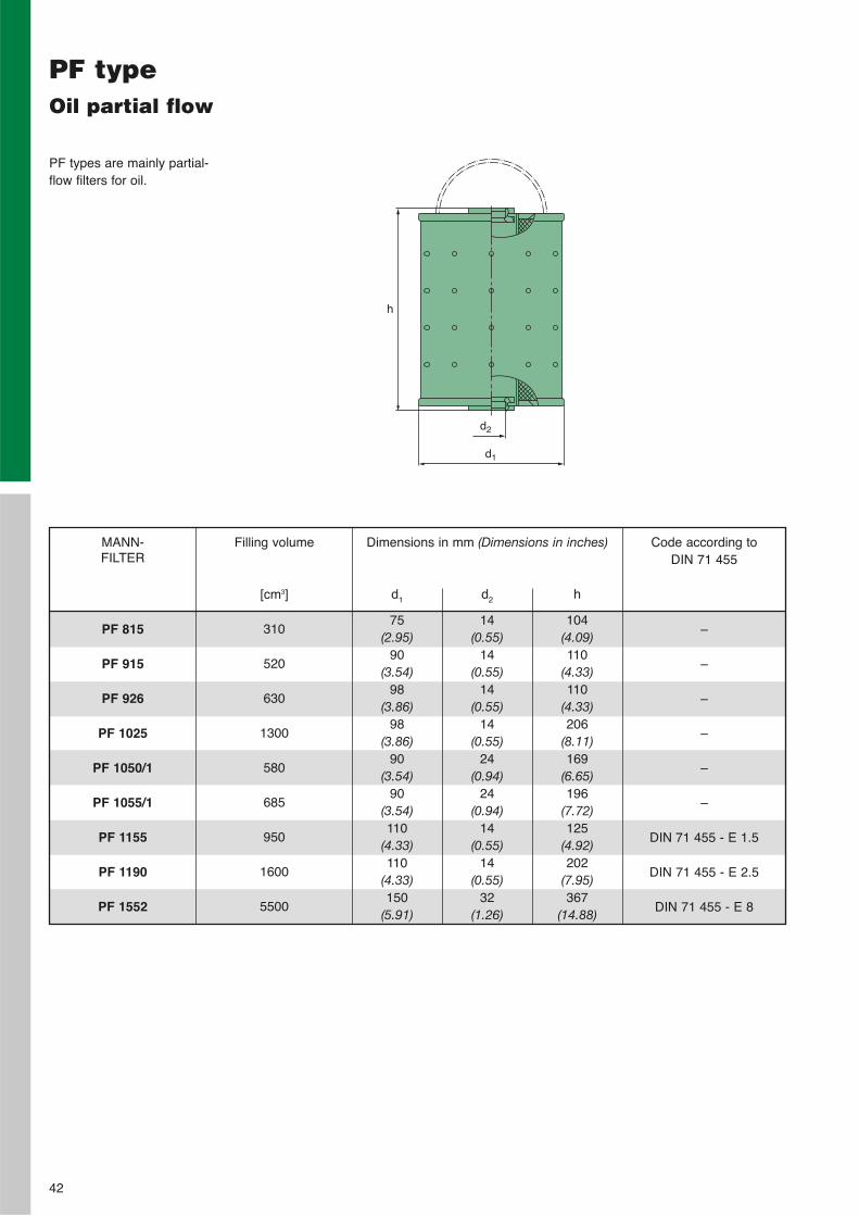
PF typeOil partial flow
PF types are mainly partial-flow filters for oil.
PF 815
PF 915
PF 926
PF 1025
PF 1050/1
PF 1055/1
PF 1155
PF 1190
PF 1552
MANN-FILTER
Dimensions in mm (Dimensions in inches)
d1
75(2.95)
90(3.54)
98(3.86)
98(3.86)
90(3.54)
90(3.54)110
(4.33)110
(4.33)150
(5.91)
d2
14(0.55)
14(0.55)
14(0.55)
14(0.55)
24(0.94)
24(0.94)
14(0.55)
14(0.55)
32(1.26)
h
104(4.09)110
(4.33)110
(4.33)206
(8.11)169
(6.65)196
(7.72)125
(4.92)202
(7.95)367
(14.88)
Filling volume
[cm3]
310
520
630
1300
580
685
950
1600
5500
Code according to DIN 71 455
–
–
–
–
–
–
DIN 71 455 - E 1.5
DIN 71 455 - E 2.5
DIN 71 455 - E 8
h
d2
d1
MANN+HUMMEL High pressure filters
43
MANN+HUMMEL Housings for high pressure filters
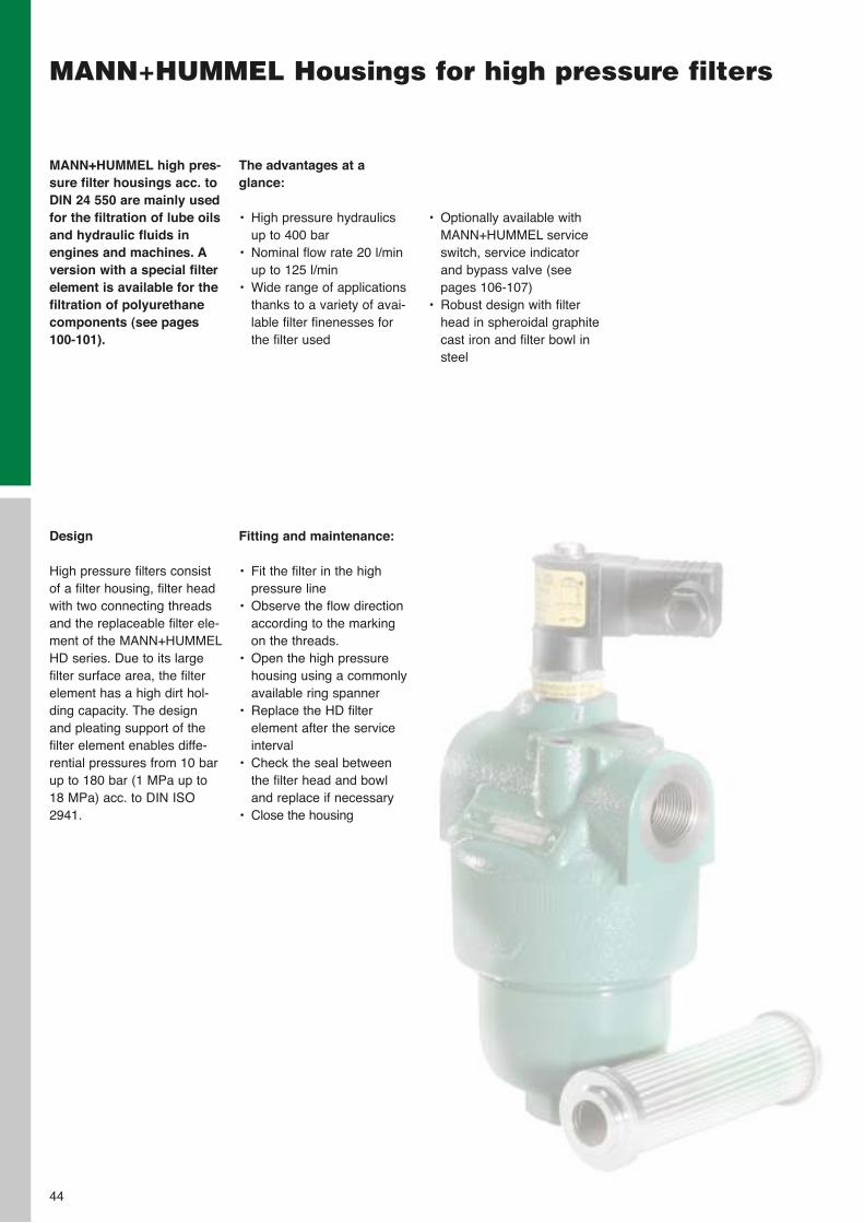
The advantages at a glance:
• High pressure hydraulicsup to 400 bar
• Nominal flow rate 20 l/minup to 125 l/min
• Wide range of applicationsthanks to a variety of avai-lable filter finenesses forthe filter used
MANN+HUMMEL high pres-sure filter housings acc. toDIN 24 550 are mainly usedfor the filtration of lube oilsand hydraulic fluids inengines and machines. Aversion with a special filterelement is available for thefiltration of polyurethanecomponents (see pages100-101).
Fitting and maintenance:
• Fit the filter in the highpressure line
• Observe the flow directionaccording to the markingon the threads.
• Open the high pressurehousing using a commonlyavailable ring spanner
• Replace the HD filter element after the serviceinterval
• Check the seal betweenthe filter head and bowland replace if necessary
• Close the housing
Design
High pressure filters consistof a filter housing, filter headwith two connecting threadsand the replaceable filter ele-ment of the MANN+HUMMELHD series. Due to its large filter surface area, the filterelement has a high dirt hol-ding capacity. The designand pleating support of thefilter element enables diffe-rential pressures from 10 barup to 180 bar (1 MPa up to18 MPa) acc. to DIN ISO2941.
44
• Optionally available withMANN+HUMMEL serviceswitch, service indicatorand bypass valve (seepages 106-107)
• Robust design with filterhead in spheroidal graphitecast iron and filter bowl insteel
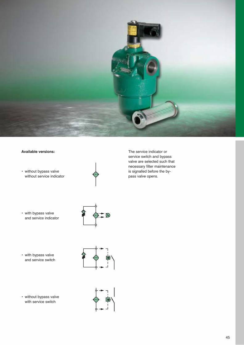
Available versions:
• without bypass valvewithout service indicator
• with bypass valveand service indicator
• with bypass valveand service switch
• without bypass valvewith service switch
45
The service indicator or service switch and bypassvalve are selected such thatnecessary filter maintenanceis signalled before the by-pass valve opens.
46
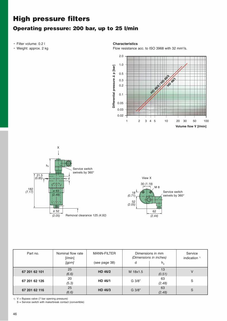
High pressure filtersOperating pressure: 200 bar, up to 25 l/min
CharacteristicsFlow resistance acc. to ISO 3968 with 32 mm2/s.
• Filter volume: 0.2 l• Weight: approx. 2 kg
ø 52
(2.05)
h2
Removal clearance 125 (4.92)
Service switch swivels by 360°
182(7.17)
21.5(0.85)
X
d
30 (1.18)
62
(2.44)
Service switch swivels by 360°
M 8
18(0.71)
52(2.05)
View X
1) V = Bypass valve (7 bar opening pressure)S = Service switch with make/break contact (convertible)
67 201 62 101
67 201 62 126
67 201 62 116
Part no. Dimensions in mm (Dimensions in inches)
d
M 18x1.5
G 3/8”
G 3/8”
h2
13(0.51)
63(2.48)
63(2.48)
Service indication 1)
V
S
S
MANN-FILTER
(see page 38)
HD 46/2
HD 46/1
HD 46/3
Volume flow V̇ [l/min]
Dif
fere
nti
al p
ress
ure
∆p
[b
ar]
2.0
1.0
0.5
0.3
0.2
0.1
0.05
0.03
0.02
1 2 3 4 5 10 20 30 50 100
HD 46/2
/ HD 4
6/3
HD 46/1
ø 63(2.48)
Nominal flow rate[l/min][gpm]
25(6.6)20
(5.3)25
(6.6)
47
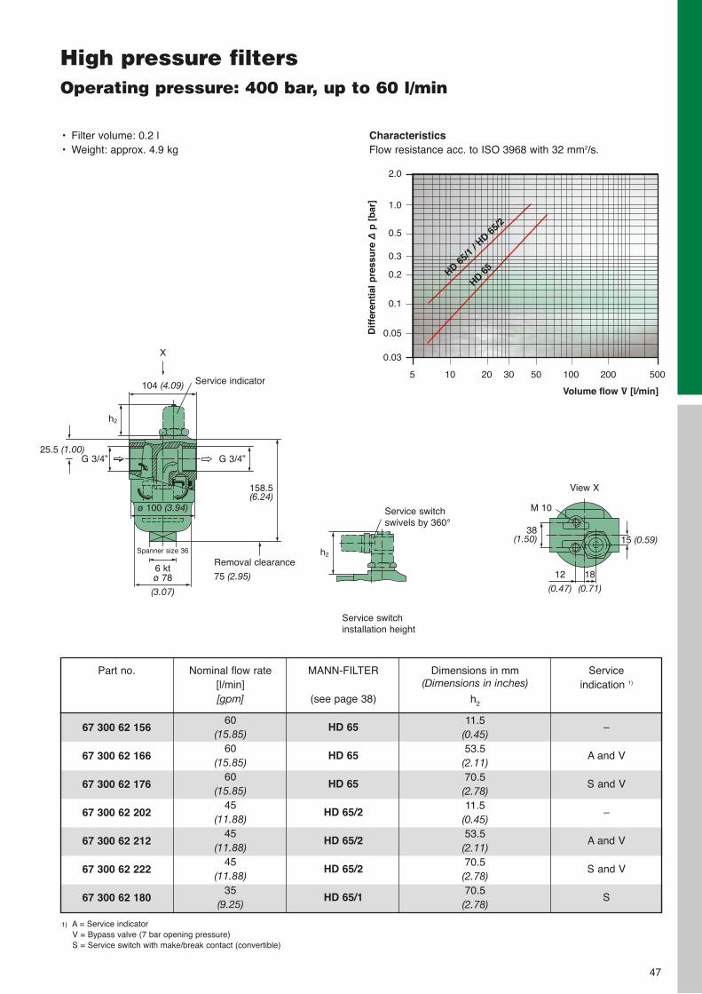
High pressure filtersOperating pressure: 400 bar, up to 60 l/min
Service switch installation height
1) A = Service indicatorV = Bypass valve (7 bar opening pressure)S = Service switch with make/break contact (convertible)
67 300 62 156
67 300 62 166
67 300 62 176
67 300 62 202
67 300 62 212
67 300 62 222
67 300 62 180
Part no. Dimensions in mm (Dimensions in inches)
h2
11.5(0.45)53.5(2.11)70.5(2.78)11.5
(0.45)53.5(2.11)70.5(2.78)70.5(2.78)
Service indication 1)
–
A and V
S and V
–
A and V
S and V
S
MANN-FILTER
(see page 38)
HD 65
HD 65
HD 65
HD 65/2
HD 65/2
HD 65/2
HD 65/1
Service switch swivels by 360°
Spanner size 36
h2
Removal clearance
75 (2.95)
25.5 (1.00)G 3/4”
X
6 ktø 78
(3.07)
Service indicator
158.5(6.24)
G 3/4”
h2
12
(0.47)
38(1.50)
M 10
15 (0.59)
18
(0.71)
View X
• Filter volume: 0.2 l• Weight: approx. 4.9 kg
104 (4.09)
ø 100 (3.94)
CharacteristicsFlow resistance acc. to ISO 3968 with 32 mm2/s.
Volume flow V̇ [l/min]
Dif
fere
nti
al p
ress
ure
∆p
[b
ar]
2.0
1.0
0.5
0.3
0.2
0.1
0.05
0.03
5 10 20 30 50 100 200 500
HD 65/1
/ HD 6
5/2
HD 65
Nominal flow rate[l/min][gpm]
60(15.85)
60(15.85)
60(15.85)
45(11.88)
45(11.88)
45(11.88)
35(9.25)
48
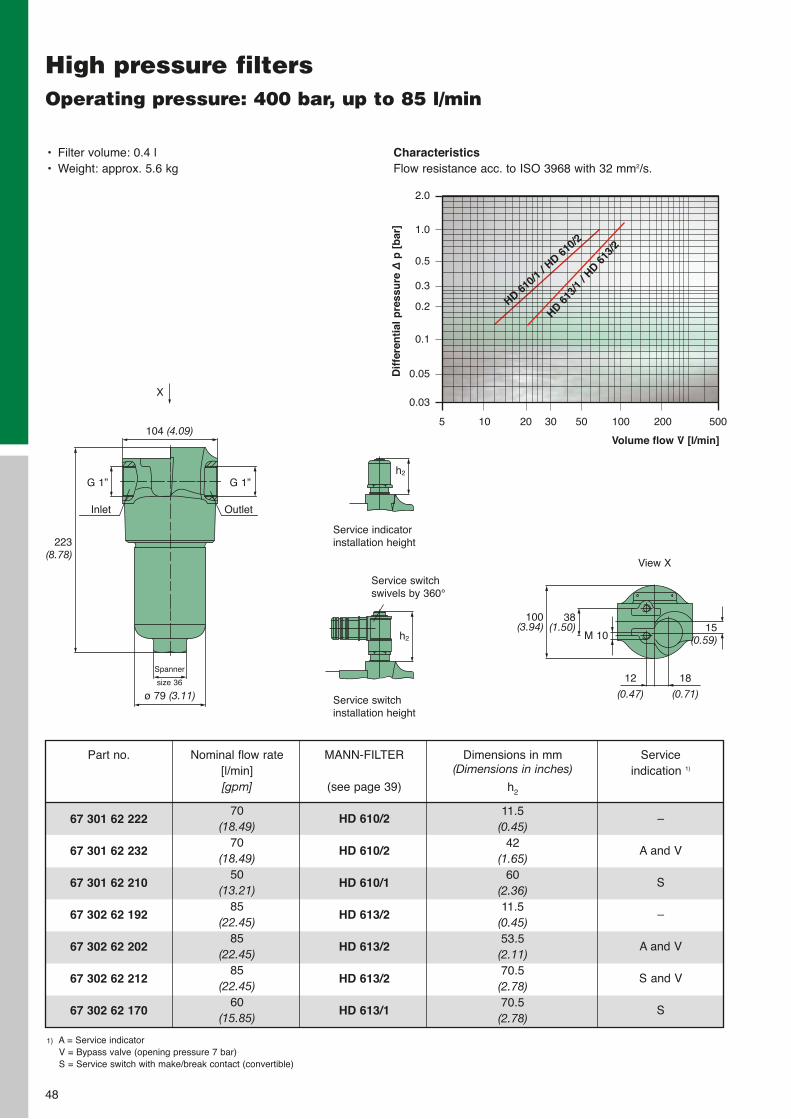
High pressure filtersOperating pressure: 400 bar, up to 85 l/min
Service switch installation height
• Filter volume: 0.4 l• Weight: approx. 5.6 kg
CharacteristicsFlow resistance acc. to ISO 3968 with 32 mm2/s.
Volume flow V̇ [l/min]
Dif
fere
nti
al p
ress
ure
∆p
[b
ar]
2.0
1.0
0.5
0.3
0.2
0.1
0.05
0.03
5 10 20 30 50 100 200 500
HD 610/1
/ HD 61
0/2
HD 613
/1 /
HD 613
/2
Spanner
size 36
223 (8.78)
G 1”
ø 79 (3.11)
Outlet
G 1”
h2 M 10
104 (4.09)
12
(0.47)
38(1.50) 15
(0.59)
18
(0.71)
Service indicatorinstallation height
h2
Inlet
100(3.94)
Service switch swivels by 360°
X
View X
1) A = Service indicatorV = Bypass valve (opening pressure 7 bar)S = Service switch with make/break contact (convertible)
67 301 62 222
67 301 62 232
67 301 62 210
67 302 62 192
67 302 62 202
67 302 62 212
67 302 62 170
Part no. Dimensions in mm (Dimensions in inches)
h2
11.5(0.45)
42(1.65)
60(2.36)11.5
(0.45)53.5(2.11)70.5(2.78)70.5(2.78)
Service indication 1)
–
A and V
S
–
A and V
S and V
S
MANN-FILTER
(see page 39)
HD 610/2
HD 610/2
HD 610/1
HD 613/2
HD 613/2
HD 613/2
HD 613/1
Nominal flow rate[l/min][gpm]
70(18.49)
70(18.49)
50(13.21)
85(22.45)
85(22.45)
85(22.45)
60(15.85)
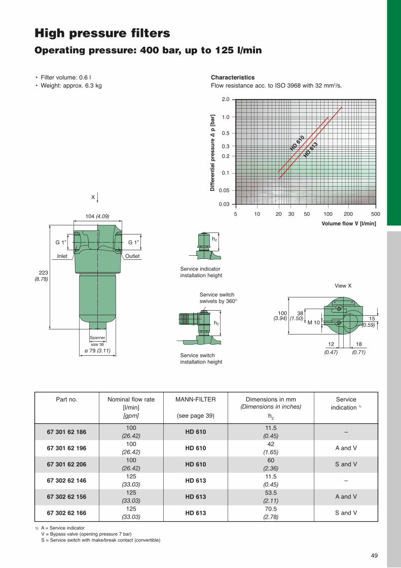
49
High pressure filtersOperating pressure: 400 bar, up to 125 l/min
• Filter volume: 0.6 l• Weight: approx. 6.3 kg
CharacteristicsFlow resistance acc. to ISO 3968 with 32 mm2/s.
Volume flow V̇ [l/min]
Dif
fere
nti
al p
ress
ure
∆p
[b
ar]
2.0
1.0
0.5
0.3
0.2
0.1
0.05
0.03
5 10 20 30 50 100 200 500
HD 613
Service switch installation height
Spanner
size 36
223 (8.78)
G 1”
ø 79 (3.11)
Outlet
G 1”
h2 M 10
104 (4.09)
12
(0.47)
38(1.50) 15
(0.59)
18
(0.71)
Service indicatorinstallation height
h2
Inlet
100(3.94)
Service switch swivels by 360°
X
View XHD 6
10
1) A = Service indicatorV = Bypass valve (opening pressure 7 bar)S = Service switch with make/break contact (convertible)
67 301 62 186
67 301 62 196
67 301 62 206
67 302 62 146
67 302 62 156
67 302 62 166
Part no. Dimensions in mm (Dimensions in inches)
h2
11.5(0.45)
42(1.65)
60(2.36)11.5
(0.45)53.5(2.11)70.5(2.78)
Service indication 1)
–
A and V
S and V
–
A and V
S and V
MANN-FILTER
(see page 39)
HD 610
HD 610
HD 610
HD 613
HD 613
HD 613
Nominal flow rate[l/min][gpm]
100(26.42)
100(26.42)
100(26.42)
125(33.03)
125(33.03)
125(33.03)

50
MANN+HUMMEL Strainer filters
51
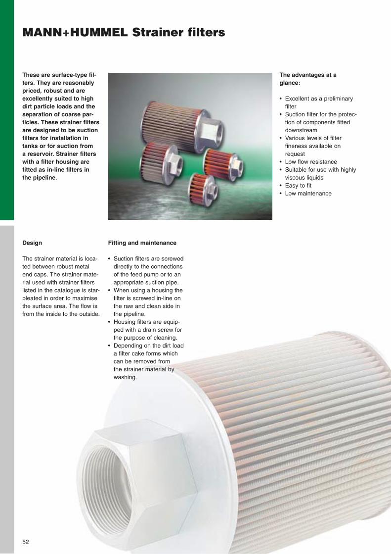
The advantages at a glance:
• Excellent as a preliminaryfilter
• Suction filter for the protec-tion of components fitteddownstream
• Various levels of filterfineness available onrequest
• Low flow resistance• Suitable for use with highly
viscous liquids• Easy to fit• Low maintenance
These are surface-type fil-ters. They are reasonablypriced, robust and areexcellently suited to highdirt particle loads and theseparation of coarse par-ticles. These strainer filtersare designed to be suctionfilters for installation intanks or for suction from a reservoir. Strainer filterswith a filter housing are fitted as in-line filters in the pipeline.
MANN+HUMMEL Strainer filters
Fitting and maintenance
• Suction filters are screweddirectly to the connectionsof the feed pump or to anappropriate suction pipe.
• When using a housing thefilter is screwed in-line onthe raw and clean side inthe pipeline.
• Housing filters are equip-ped with a drain screw forthe purpose of cleaning.
• Depending on the dirt loada filter cake forms whichcan be removed from the strainer material by washing.
Design
The strainer material is loca-ted between robust metalend caps. The strainer mate-rial used with strainer filterslisted in the catalogue is star-pleated in order to maximisethe surface area. The flow isfrom the inside to the outside.
52
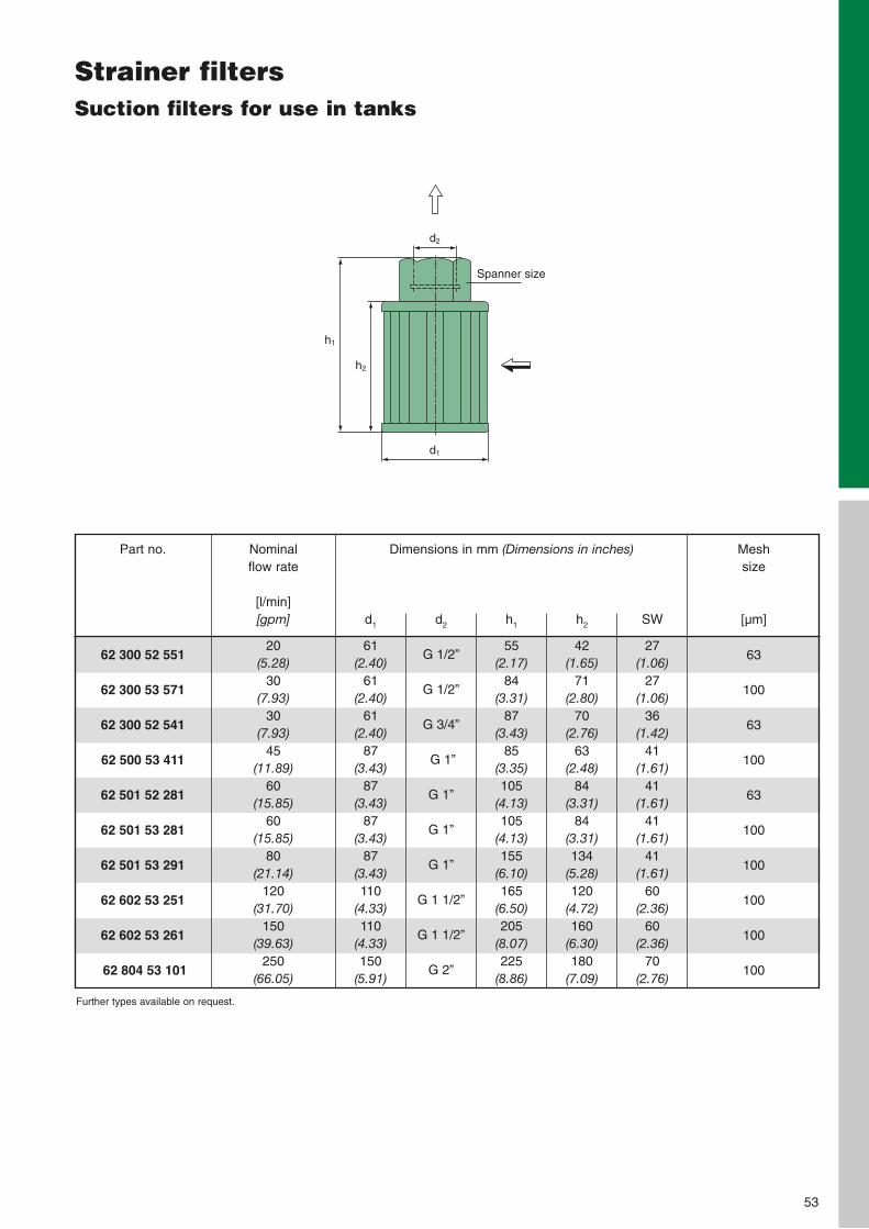
53
Strainer filtersSuction filters for use in tanks
62 300 52 551
62 300 53 571
62 300 52 541
62 500 53 411
62 501 52 281
62 501 53 281
62 501 53 291
62 602 53 251
62 602 53 261
62 804 53 101
Part no. Dimensions in mm (Dimensions in inches)
d2
G 1/2”
G 1/2”
G 3/4”
G 1”
G 1”
G 1”
G 1”
G 1 1/2”
G 1 1/2”
G 2”
d1
61(2.40)
61(2.40)
61(2.40)
87(3.43)
87(3.43)
87(3.43)
87(3.43)110
(4.33)110
(4.33)150
(5.91)
h1
55(2.17)
84(3.31)
87(3.43)
85(3.35)105
(4.13)105
(4.13)155
(6.10)165
(6.50)205
(8.07)225
(8.86)
h2
42(1.65)
71(2.80)
70(2.76)
63(2.48)
84(3.31)
84(3.31)134
(5.28)120
(4.72)160
(6.30)180
(7.09)
SW
27(1.06)
27(1.06)
36(1.42)
41(1.61)
41(1.61)
41(1.61)
41(1.61)
60(2.36)
60(2.36)
70(2.76)
Mesh size
[µm]
63
100
63
100
63
100
100
100
100
100
Nominal flow rate
[l/min][gpm]
20(5.28)
30(7.93)
30(7.93)
45(11.89)
60(15.85)
60(15.85)
80(21.14)
120(31.70)
150(39.63)
250(66.05)
d2
d1
h2
h1
Spanner size
Further types available on request.
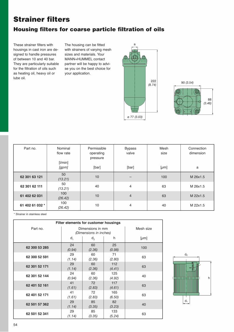
Strainer filtersHousing filters for coarse particle filtration of oils
54
These strainer filters withhousings in cast iron are de-signed to handle pressures of between 10 and 40 bar.They are particularly suitablefor the filtration of oils suchas heating oil, heavy oil orlube oil.
The housing can be fittedwith strainers of varying meshsizes and materials. YourMANN+HUMMEL contactpartner will be happy to advi-se you on the best choice foryour application.
62 301 63 121
62 301 62 111
61 402 62 031
61 402 61 032 *
Part no. Mesh size
[µm]
100
63
63
40
Connection dimension
a
M 26x1.5
M 26x1.5
M 22x1.5
M 22x1.5
Nominal flow rate
[l/min][gpm]
50(13.21)
50(13.21)
100(26.42)
100(26.42)
Permissible operating pressure
[bar]
10
40
10
10
Bypass valve
[bar]
–
4
4
4
* Strainer in stainless steel
a
ø 77 (3.03)
90 (3.54)222 (8.74)
88 (3.46)
Filter elements for customer housings
62 300 53 285
62 300 52 591
62 301 52 171
62 301 52 144
62 401 52 161
62 401 52 171
62 501 57 362
62 501 52 341
Part no. Dimensions in mm (Dimensions in inches)
d2
60(2.36)
60(2.36)
60(2.36)
60(2.36)
72(2.83)
72(2.83)
85(3.35)
85(3.35)
d1
24(0.94)
29(1.14)
29(1.14)
24(0.94)
41(1.61)
41(1.61)
29(1.14)
29(1.14)
h
25(0.98)
71(2.80)112
(4.41)125
(4.92)117
(4.61)165
(6.50)82
(3.23)133
(5.24)
Mesh size
[µm]
100
63
63
40
63
63
40
63
d2
d1
h
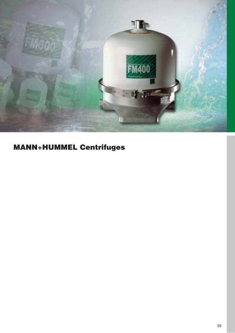
MANN+HUMMEL Centrifuges
55
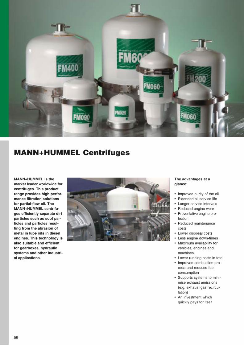
MANN+HUMMEL Centrifuges
MANN+HUMMEL is themarket leader worldwide forcentrifuges. This productrange provides high perfor-mance filtration solutionsfor partial-flow oil. TheMANN+HUMMEL centrifu-ges efficiently separate dirtparticles such as soot par-ticles and particles resul-ting from the abrasion ofmetal in lube oils in dieselengines. This technology isalso suitable and efficientfor gearboxes, hydraulicsystems and other industri-al applications.
56
The advantages at a glance:
• Improved purity of the oil• Extended oil service life • Longer service intervals • Reduced engine wear• Preventative engine pro-
tection• Reduced maintenance
costs• Lower disposal costs• Less engine down-times• Maximum availability for
vehicles, engines andmachines
• Lower running costs in total• Improved combustion pro-
cess and reduced fuel consumption
• Supports systems to mini-mise exhaust emissions(e.g. exhaust gas recircu-lation)
• An investment which quickly pays for itself
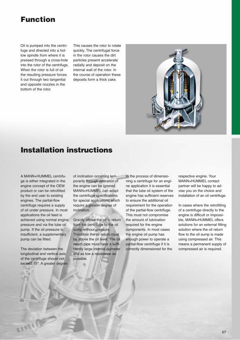
Function
Oil is pumped into the centri-fuge and directed into a hol-low spindle from where it ispressed through a cross-holeinto the rotor of the centrifuge.When the rotor is full of oilthe resulting pressure forcesit out through two tangentialand opposite nozzles in thebottom of the rotor.
This causes the rotor to rotatequickly. The centrifugal forcein the rotor causes the dirtparticles present accelerateradially and deposit on theinternal wall of the rotor. Inthe course of operation thesedeposits form a thick cake.
57
Installation instructions
of inclination occurring tem-porarily through operation ofthe engine can be ignored.MANN+HUMMEL can adaptthe centrifuge specificationsfor special applications whichrequire a greater degree ofinclination.
Gravity allows the oil to returnfrom the centrifuge to the oilsump without pressure.Therefore the oil return mustbe above the oil level. The oilreturn pipe must have a suffi-ciently large internal diameterand as low a resistance aspossible.
A MANN+HUMMEL centrifu-ge is either integrated in theengine concept of the OEMproduct or can be retrofittedby the end user to existingengines. The partial-flow centrifuge requires a supplyof oil under pressure. In mostapplications the oil feed isachieved using normal enginepressure and via the lube oilpump. If the oil pressure isinsufficient, a supplementarypump can be fitted.
The deviation between thelongitudinal and vertical axisof the centrifuge should notexceed 15°. A greater degree
respective engine. YourMANN+HUMMEL contactpartner will be happy to ad-vise you on the choice andinstallation of an oil centrifuge.
In cases where the retrofittingof a centrifuge directly to theengine is difficult or impossi-ble, MANN+HUMMEL offerssolutions for an external fittingsolution where the oil returnflow to the oil sump is madeusing compressed air. Thismeans a permanent supply ofcompressed air is required.
In the process of dimensio-ning a centrifuge for an engi-ne application it is essentialthat the lube oil system of theengine has sufficient reservesto ensure the additional oilrequirement for the operationof the partial-flow centrifuge.This must not compromisethe amount of lubricationrequired for the engine components. In most casesthe engine oil pump hasenough power to operate apartial-flow centrifuge if it iscorrectly dimensioned for the
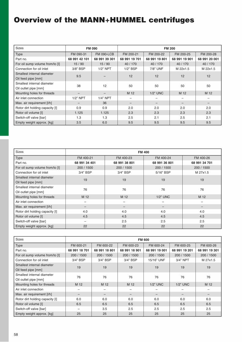
58
Overview of the MANN+HUMMEL centrifuges
Sizes
Type
Part no.
For oil sump volume from/to [l]
Connection for oil inlet
Smallest internal diameter
Oil feed pipe [mm]
Smallest internal diameter
Oil outlet pipe [mm]
Mounting holes for threads
Air inlet connection
Max. air requirement [l/h]
Rotor dirt holding capacity [l]
Rotor oil volume [l]
Switch-off valve [bar]
Empty weight approx. [kg]
FM 090-31
68 991 42 101
15 / 90
3/8” BSP
9.5
38
–
1/2” NPT
–
0.9
1.125
1.3
3.5
FM 090-LCB
68 991 39 301
15 / 90
1/2” NPT
–
12
–
1/4” NPT
36
0.9
1.125
1.3
6.0
FM 200-21
68 991 19 701
40 / 170
1/2” BSP
12
50
M 12
–
–
2.0
2.3
2.5
9.5
FM 200-22
68 991 19 801
40 / 170
7/8” UNF
12
50
1/2” UNC
–
–
2.0
2.3
2.1
9.5
FM 200-25
68 991 19 901
40 / 170
M 22x1.5
12
50
M 12
–
–
2.0
2.3
2.5
9.5
FM 200-28
68 991 20 001
40 / 170
M 22x1.5
12
50
M 12
–
–
2.0
2.3
2.1
9.5
FM 090 FM 200
Sizes
Type
Part no.
For oil sump volume from/to [l]
Connection for oil inlet
Smallest internal diameter
Oil feed pipe [mm]
Smallest internal diameter
Oil outlet pipe [mm]
Mounting holes for threads
Air inlet connection
Max. air requirement [l/h]
Rotor dirt holding capacity [l]
Rotor oil volume [l]
Switch-off valve [bar]
Empty weight approx. [kg]
FM 400-21
68 991 34 401
200 / 1500
3/4” BSP
19
76
M 12
–
–
4.0
4.5
–
22
FM 400-23
68 991 38 801
200 / 1500
3/4” BSP
19
76
M 12
–
–
4.0
4.5
2.5
22
FM 400-24
68 991 36 801
200 / 1500
5/16” BSP
19
76
1/2” UNC
–
–
4.0
4.5
2.5
22
FM 400-26
68 991 34 701
200 / 1500
M 27x1.5
19
76
M 12
–
–
4.0
4.5
2.5
22
FM 400
Sizes
Type
Part no.
For oil sump volume from/to [l]
Connection for oil inlet
Smallest internal diameter
Oil feed pipe [mm]
Smallest internal diameter
Oil outlet pipe [mm]
Mounting holes for threads
Air inlet connection
Max. air requirement [l/h]
Rotor dirt holding capacity [l]
Rotor oil volume [l]
Switch-off valve [bar]
Empty weight approx. [kg]
FM 600-21
68 991 18 701
200 / 1500
3/4” BSP
19
76
M 12
–
–
6.0
6.5
–
25
FM 600-22
68 991 18 801
200 / 1500
3/4” BSP
19
76
M 12
–
–
6.0
6.5
3.5
25
FM 600-23
68 991 18 901
200 / 1500
3/4” BSP
19
76
M 12
–
–
6.0
6.5
2.5
25
FM 600-24
68 991 19 001
200 / 1500
15/16” UNF
19
76
1/2” UNC
–
–
6.0
6.5
2.5
25
FM 600-25
68 991 19 201
200 / 1500
3/4” NPT
19
76
1/2” UNC
–
–
6.0
6.5
2.5
25
FM 600-26
68 991 19 301
200 / 1500
M 27x1.5
19
76
M 12
–
–
6.0
6.5
2.5
25
FM 600
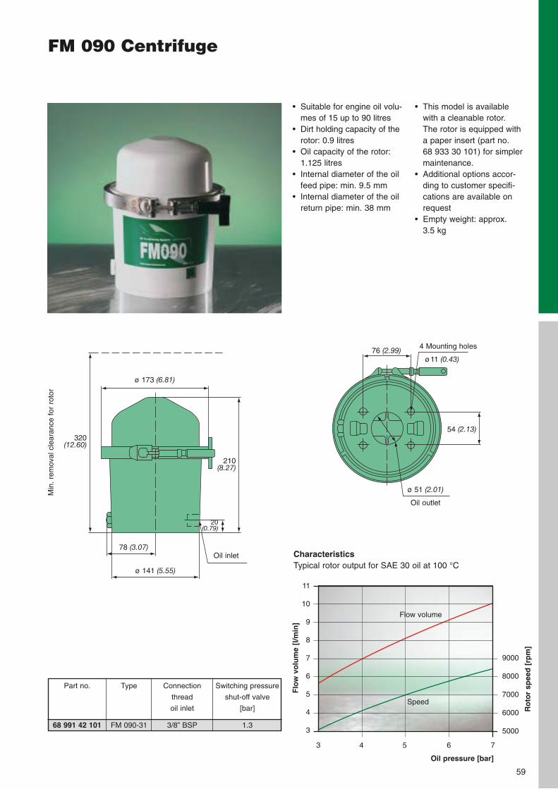
59
FM 090 Centrifuge
• This model is available with a cleanable rotor. The rotor is equipped witha paper insert (part no. 68 933 30 101) for simplermaintenance.
• Additional options accor-ding to customer specifi-cations are available onrequest
• Empty weight: approx. 3.5 kg
• Suitable for engine oil volu-mes of 15 up to 90 litres
• Dirt holding capacity of therotor: 0.9 litres
• Oil capacity of the rotor:1.125 litres
• Internal diameter of the oilfeed pipe: min. 9.5 mm
• Internal diameter of the oilreturn pipe: min. 38 mm
4 Mounting holes
ø11 (0.43)76 (2.99)
ø 51 (2.01)
Oil outlet
54 (2.13)
ø 173 (6.81)
320(12.60)
210(8.27)
20(0.79)
ø 141 (5.55)
78 (3.07)Oil inlet
Min
. re
mov
al c
lear
ance
for
rot
or
CharacteristicsTypical rotor output for SAE 30 oil at 100 °C
Part no.
68 991 42 101
Connection
thread
oil inlet
3/8” BSP
Switching pressure
shut-off valve
[bar]
1.3
Type
FM 090-31
Oil pressure [bar]
Flo
w v
olu
me
[l/m
in]
3 4 5 6 7
9000
8000
7000
6000
5000
Ro
tor
spee
d [
rpm
]
Speed
Flow volume
11
10
9
8
7
6
5
4
3
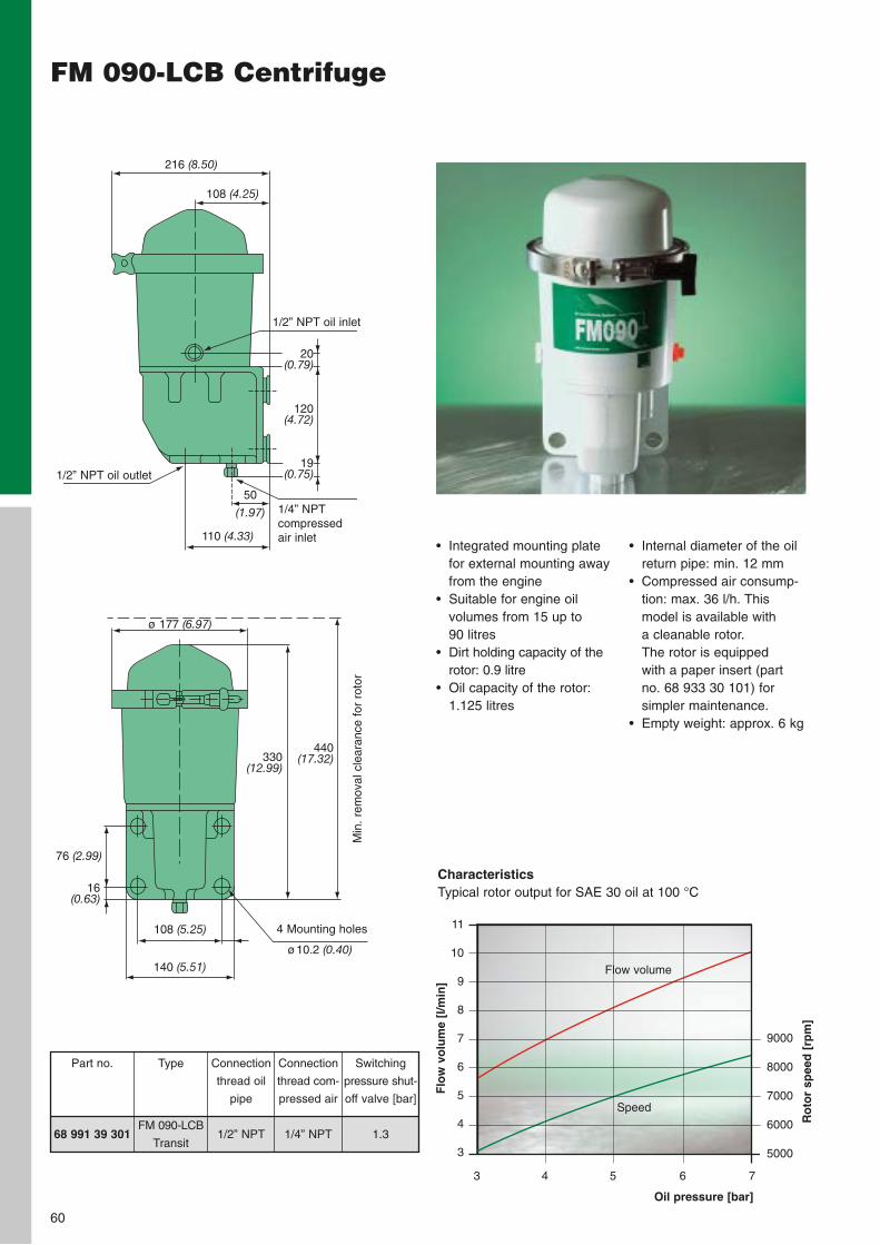
60
FM 090-LCB Centrifuge
• Integrated mounting platefor external mounting awayfrom the engine
• Suitable for engine oilvolumes from 15 up to 90 litres
• Dirt holding capacity of therotor: 0.9 litre
• Oil capacity of the rotor:1.125 litres
216 (8.50)
108 (4.25)
50
(1.97)
110 (4.33)
120(4.72)
1/2” NPT oil inlet
1/2” NPT oil outlet
1/4” NPTcompressed air inlet
76 (2.99)
16(0.63)
ø 177 (6.97)
4 Mounting holes
ø10.2 (0.40)
108 (5.25)
140 (5.51)
Min
. re
mov
al c
lear
ance
for
rot
or
• Internal diameter of the oilreturn pipe: min. 12 mm
• Compressed air consump-tion: max. 36 l/h. Thismodel is available with a cleanable rotor. The rotor is equipped with a paper insert (partno. 68 933 30 101) forsimpler maintenance.
• Empty weight: approx. 6 kg
CharacteristicsTypical rotor output for SAE 30 oil at 100 °C
Oil pressure [bar]
Flo
w v
olu
me
[l/m
in]
3 4 5 6 7
9000
8000
7000
6000
5000
Ro
tor
spee
d [
rpm
]
Speed
Flow volume
11
10
9
8
7
6
5
4
3
20(0.79)
19(0.75)
330(12.99)
440(17.32)
Type
FM 090-LCB
Transit
Connection
thread oil
pipe
1/2” NPT
Connection
thread com-
pressed air
1/4” NPT
Switching
pressure shut-
off valve [bar]
1.3
Part no.
68 991 39 301
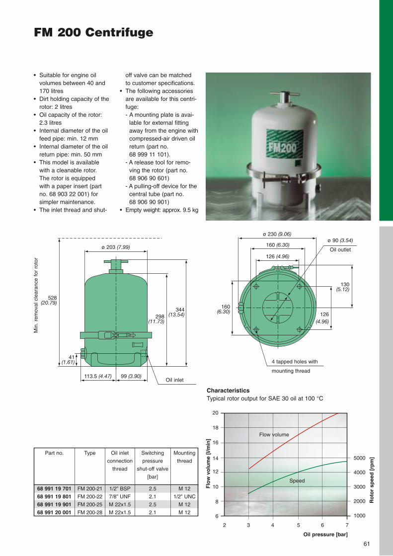
61
FM 200 Centrifuge
off valve can be matched to customer specifications.
• The following accessoriesare available for this centri-fuge: - A mounting plate is avai-
lable for external fittingaway from the engine withcompressed-air driven oilreturn (part no. 68 999 11 101).
- A release tool for remo-ving the rotor (part no. 68 906 90 601)
- A pulling-off device for thecentral tube (part no. 68 906 90 901)
• Empty weight: approx. 9.5 kg
• Suitable for engine oil volumes between 40 and170 litres
• Dirt holding capacity of therotor: 2 litres
• Oil capacity of the rotor: 2.3 litres
• Internal diameter of the oilfeed pipe: min. 12 mm
• Internal diameter of the oilreturn pipe: min. 50 mm
• This model is available with a cleanable rotor. The rotor is equipped with a paper insert (part no. 68 903 22 001) forsimpler maintenance.
• The inlet thread and shut-
ø 90 (3.54)
Oil outlet
ø 230 (9.06)
4 tapped holes with
mounting thread
ø 203 (7.99)
113.5 (4.47)Oil inlet
Min
. re
mov
al c
lear
ance
for
rot
or
160 (6.30)
126 (4.96)
126 (4.96)
99 (3.90)
CharacteristicsTypical rotor output for SAE 30 oil at 100 °C
Oil pressure [bar]
Flo
w v
olu
me
[l/m
in]
2 3 4 5 6 7
5000
4000
3000
2000
1000
Ro
tor
spee
d [
rpm
]
Speed
Flow volume
20
18
16
14
12
10
8
6
528(20.79)
298(11.73)
344(13.54)
41(1.61)
160(6.30)
130(5.12)
Type
FM 200-21
FM 200-22
FM 200-25
FM 200-28
Oil inlet
connection
thread
1/2” BSP
7/8” UNF
M 22x1.5
M 22x1.5
Switching
pressure
shut-off valve
[bar]
2.5
2.1
2.5
2.1
Mounting
thread
M 12
1/2” UNC
M 12
M 12
Part no.
68 991 19 701
68 991 19 801
68 991 19 901
68 991 20 001
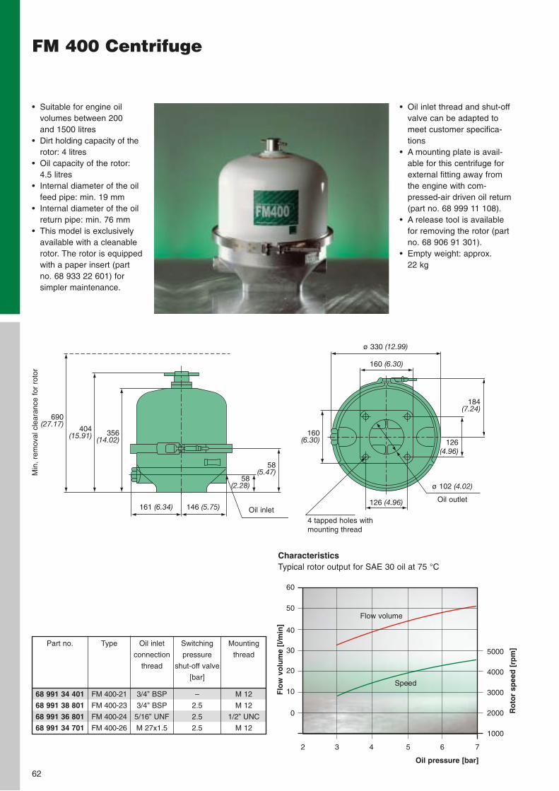
62
FM 400 Centrifuge
• Oil inlet thread and shut-offvalve can be adapted tomeet customer specifica-tions
• A mounting plate is avail-able for this centrifuge forexternal fitting away fromthe engine with com-pressed-air driven oil return(part no. 68 999 11 108).
• A release tool is availablefor removing the rotor (partno. 68 906 91 301).
• Empty weight: approx. 22 kg
• Suitable for engine oil volumes between 200 and 1500 litres
• Dirt holding capacity of therotor: 4 litres
• Oil capacity of the rotor:4.5 litres
• Internal diameter of the oilfeed pipe: min. 19 mm
• Internal diameter of the oilreturn pipe: min. 76 mm
• This model is exclusivelyavailable with a cleanablerotor. The rotor is equippedwith a paper insert (partno. 68 933 22 601) for simpler maintenance.
ø 102 (4.02)
Oil outlet
ø 330 (12.99)
4 tapped holes withmounting thread
161 (6.34) Oil inlet
Min
. re
mov
al c
lear
ance
for
rot
or
160 (6.30)
126 (4.96)
126 (4.96)
146 (5.75)
CharacteristicsTypical rotor output for SAE 30 oil at 75 °C
Oil pressure [bar]
Flo
w v
olu
me
[l/m
in]
2 3 4 5 6 7
5000
4000
3000
2000
1000
Ro
tor
spee
d [
rpm
]
Speed
Flow volume
60
50
40
30
20
10
0
356(14.02)
690(27.17)
404(15.91)
58(2.28)
58(5.47)
184(7.24)
160(6.30)
Type
FM 400-21
FM 400-23
FM 400-24
FM 400-26
Oil inlet
connection
thread
3/4” BSP
3/4” BSP
5/16” UNF
M 27x1.5
Switching
pressure
shut-off valve
[bar]
–
2.5
2.5
2.5
Mounting
thread
M 12
M 12
1/2” UNC
M 12
Part no.
68 991 34 401
68 991 38 801
68 991 36 801
68 991 34 701
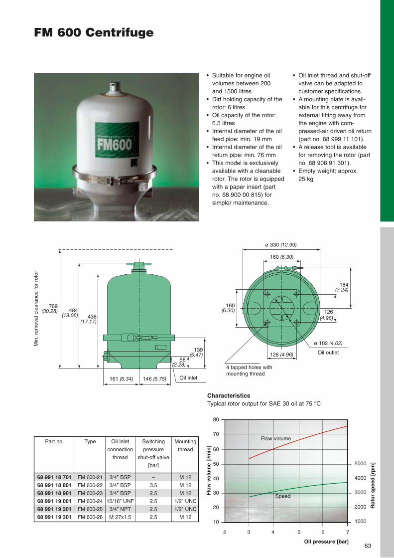
63
FM 600 Centrifuge
• Oil inlet thread and shut-offvalve can be adapted tocustomer specifications
• A mounting plate is avail-able for this centrifuge forexternal fitting away fromthe engine with com-pressed-air driven oil return(part no. 68 999 11 101).
• A release tool is availablefor removing the rotor (partno. 68 906 91 301).
• Empty weight: approx. 25 kg
• Suitable for engine oil volumes between 200 and 1500 litres
• Dirt holding capacity of therotor: 6 litres
• Oil capacity of the rotor:6.5 litres
• Internal diameter of the oilfeed pipe: min. 19 mm
• Internal diameter of the oilreturn pipe: min. 76 mm
• This model is exclusivelyavailable with a cleanablerotor. The rotor is equippedwith a paper insert (partno. 68 900 00 815) for simpler maintenance.
ø 102 (4.02)
Oil outlet
ø 330 (12.99)
4 tapped holes withmounting thread
161 (6.34) Oil inlet
Min
. re
mov
al c
lear
ance
for
rot
or
160 (6.30)
126 (4.96)
146 (5.75)
CharacteristicsTypical rotor output for SAE 30 oil at 75 °C
Oil pressure [bar]
Flo
w v
olu
me
[l/m
in]
2 3 4 5 6 7
5000
4000
3000
2000
1000
Ro
tor
spee
d [
rpm
]
Speed
Flow volume
80
70
60
50
40
30
20
10
126 (4.96)
160(6.30)
184(7.24)
769(30.28) 484
(19.06) 436(17.17)
139(5.47)
58(2.28)
Part no.
68 991 18 701
68 991 18 801
68 991 18 901
68 991 19 001
68 991 19 201
68 991 19 301
Oil inlet
connection
thread
3/4” BSP
3/4” BSP
3/4” BSP
15/16” UNF
3/4” NPT
M 27x1.5
Switching
pressure
shut-off valve
[bar]
–
3.5
2.5
2.5
2.5
2.5
Mounting
thread
M 12
M 12
M 12
1/2” UNC
1/2” UNC
M 12
Type
FM 600-21
FM 600-22
FM 600-23
FM 600-24
FM 600-25
FM 600-26

64
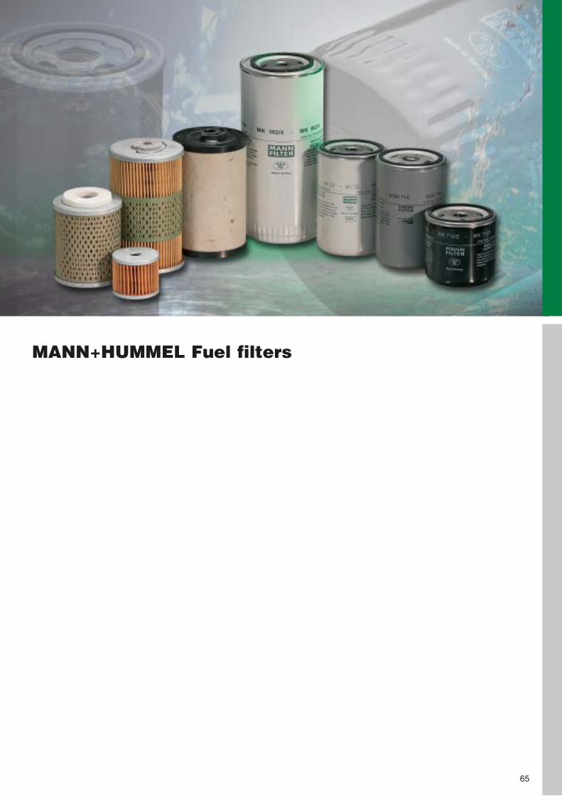
MANN+HUMMEL Fuel filters
65
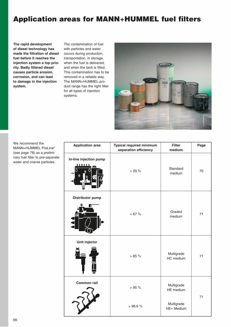
The rapid development of diesel technology hasmade the filtration of dieselfuel before it reaches theinjection system a top prio-rity. Badly filtered dieselcauses particle erosion,corrosion, and can lead to damage in the injectionsystem.
66
Application areas for MANN+HUMMEL fuel filters
We recommend theMANN+HUMMEL PreLine®
(see page 78) as a prelimi-nary fuel filter to pre-separatewater and coarse particles.
The contamination of fuelwith particles and wateroccurs during production,transportation, in storage,when the fuel is delivered,and when the tank is filled.This contamination has to beremoved in a reliable way.The MANN+HUMMEL pro-duct range has the right filterfor all types of injectionsystems.
Typical required minimumseparation efficiency
> 20 %
> 67 %
> 85 %
> 95 %
> 98.6 %
Filter medium
Standard medium
Graded medium
Multigrade HC medium
Multigrade HE medium
Multigrade HE+ Medium
Page
70
71
71
71
Application area
In-line injection pump
Distributor pump
Unit injector
Common rail
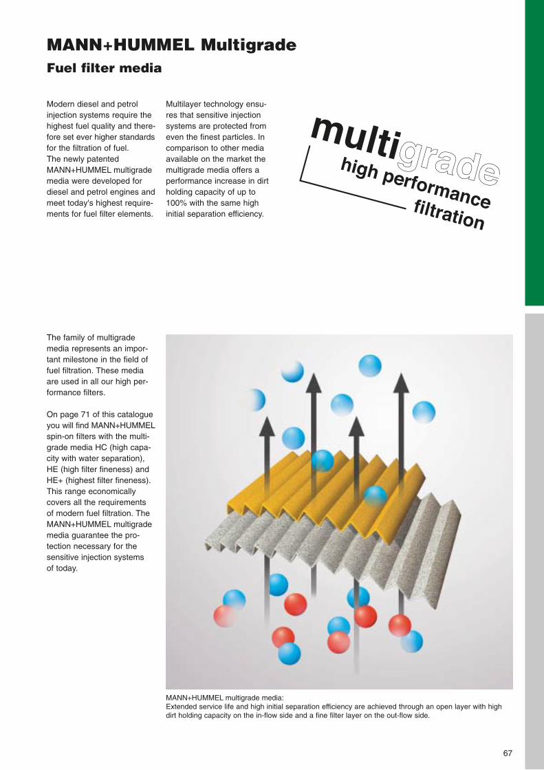
MANN+HUMMEL MultigradeFuel filter media
67
Modern diesel and petrolinjection systems require thehighest fuel quality and there-fore set ever higher standardsfor the filtration of fuel. The newly patentedMANN+HUMMEL multigrademedia were developed fordiesel and petrol engines andmeet today's highest require-ments for fuel filter elements.
The family of multigrademedia represents an impor-tant milestone in the field offuel filtration. These mediaare used in all our high per-formance filters.
On page 71 of this catalogueyou will find MANN+HUMMELspin-on filters with the multi-grade media HC (high capa-city with water separation),HE (high filter fineness) andHE+ (highest filter fineness).This range economicallycovers all the requirements of modern fuel filtration. TheMANN+HUMMEL multigrademedia guarantee the pro-tection necessary for the sensitive injection systems of today.
Multilayer technology ensu-res that sensitive injectionsystems are protected fromeven the finest particles. Incomparison to other mediaavailable on the market themultigrade media offers aperformance increase in dirtholding capacity of up to100% with the same highinitial separation efficiency.
MANN+HUMMEL multigrade media:Extended service life and high initial separation efficiency are achieved through an open layer with highdirt holding capacity on the in-flow side and a fine filter layer on the out-flow side.
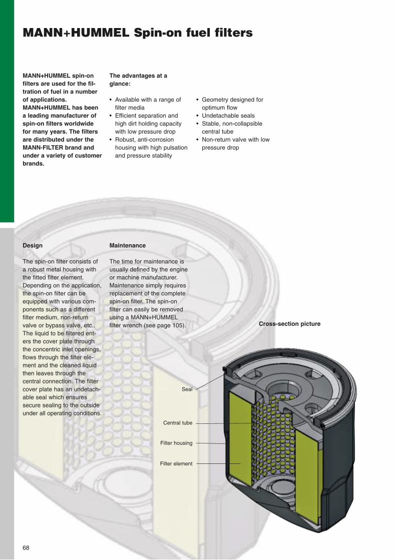
The advantages at a glance:
• Available with a range offilter media
• Efficient separation andhigh dirt holding capacitywith low pressure drop
• Robust, anti-corrosion housing with high pulsationand pressure stability
MANN+HUMMEL spin-onfilters are used for the fil-tration of fuel in a numberof applications.MANN+HUMMEL has beena leading manufacturer ofspin-on filters worldwidefor many years. The filtersare distributed under theMANN-FILTER brand andunder a variety of customerbrands.
• Geometry designed foroptimum flow
• Undetachable seals• Stable, non-collapsible
central tube• Non-return valve with low
pressure drop
MANN+HUMMEL Spin-on fuel filters
Maintenance
The time for maintenance isusually defined by the engineor machine manufacturer.Maintenance simply requiresreplacement of the completespin-on filter. The spin-on filter can easily be removedusing a MANN+HUMMELfilter wrench (see page 105).
Design
The spin-on filter consists ofa robust metal housing withthe fitted filter element.Depending on the application,the spin-on filter can beequipped with various com-ponents such as a differentfilter medium, non-returnvalve or bypass valve, etc..The liquid to be filtered ent-ers the cover plate throughthe concentric inlet openings,flows through the filter ele-ment and the cleaned liquidthen leaves through the central connection. The filtercover plate has an undetach-able seal which ensuressecure sealing to the outsideunder all operating conditions.
Filter element
Central tube
Filter housing
Seal
68
Cross-section picture
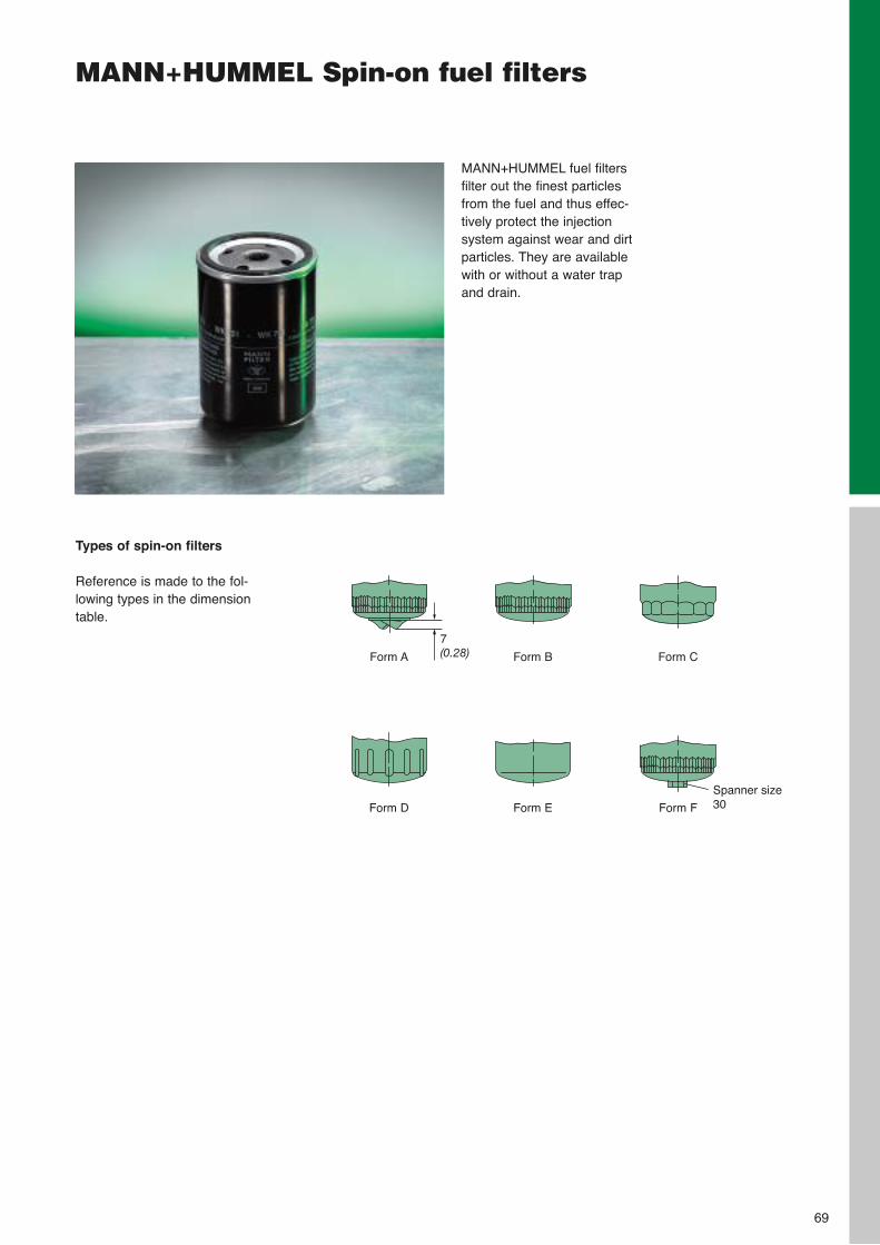
MANN+HUMMEL Spin-on fuel filters
MANN+HUMMEL fuel filtersfilter out the finest particlesfrom the fuel and thus effec-tively protect the injectionsystem against wear and dirtparticles. They are availablewith or without a water trapand drain.
Types of spin-on filters
Reference is made to the fol-lowing types in the dimensiontable.
Form A
Form D
Form B
Form E
Form C
Form F
7(0.28)
Spanner size30
69
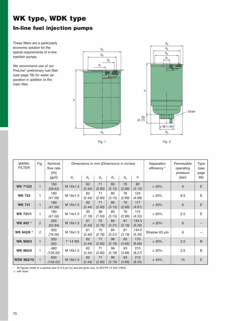
70
WK type, WDK typeIn-line fuel injection pumps
These filters are a particularlyeconomic solution for the typical requirements of in-lineinjection pumps.
We recommend use of ourPreLine® preliminary fuel filter(see page 78) for water se-paration in addition to themain filter.
WK 712/2
WK 723
WK 731
WK 731/1
WK 842 1)
WK 842/6 1)
WK 950/3
WK 962/4
WDK 962/10
MANN-FILTER
Dimensions in mm (Dimensions in inches)
d1
M 16x1.5
M 16x1.5
M 16x1.5
M 14x1.5
M 16x1.5
M 16x1.5
1“-14 NS
M 16x1.5
M 16x1.5
d2
62(2.44)
62(2.44)
62(2.44)
30(1.18)
61(2.40)
61(2.40)
62(2.44)
62(2.44)
62(2.44)
d3
71(2.80)
71(2.80)
71(2.80)
38(1.50)
70(2.76)
70(2.76)
71(2.80)
71(2.80)
71(2.80)
d4
80(3.15)
80(3.15)
80(3.15)
80(3.15)
84(3.31)
84(3.31)
96(3.78)
96(3.78)
96(3.78)
d5
76(2.99)
76(2.99)
76(2.99)
76(2.99)
81(3.19)
81(3.19)
93(3.66)
93(3.66)
93(3.66)
h
80(3.15)124
(4.88)117
(4.61)115
(4.53)134.5(5.30)134.5(5.30)170
(6.69)210
(8.27)212
(8.35)
Separation efficiency *
> 20%
> 20%
> 20%
> 20%
> 20%
Strainer 63 µm
> 20%
> 20%
> 45%
Permissibleoperatingpressure
[bar]
6
9.5
6
2.5
6
6
2.5
2.5
15
Type(seepage69)
E
E
E
E
–
–
B
B
E
Nominalflow rate
[l/h][gph]
150(39.63)
180(47.56)
180(47.56)
180(47.56)
200(52.84)
300(79.26)
350(92)480
(126.82)600
(158.52)
Drain
d4
h
h
55(2.17)
ø 38 (1.50)
d3
d2
d1
d5 d5
d4
d3
d2
d1
Fig. 1 Fig. 2
Fig.
1
1
1
1
2
2
1
1
1
* All figures relate to a particle size of 3-5 µm (c) and are given acc. to ISO/TR 13 353 (1994).1) with drain
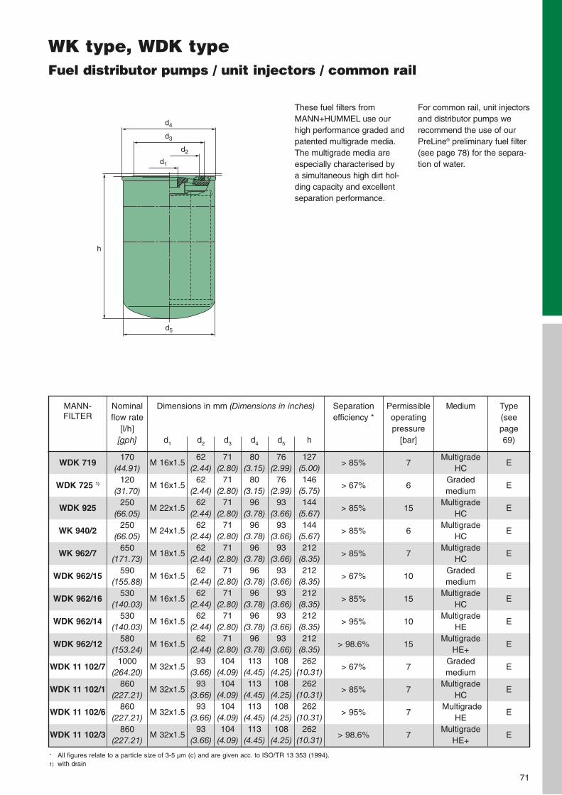
71
WK type, WDK typeFuel distributor pumps / unit injectors / common rail
d4
h
d3
d2
d1
d5
These fuel filters fromMANN+HUMMEL use ourhigh performance graded andpatented multigrade media.The multigrade media areespecially characterised by a simultaneous high dirt hol-ding capacity and excellentseparation performance.
For common rail, unit injectorsand distributor pumps werecommend the use of ourPreLine® preliminary fuel filter(see page 78) for the separa-tion of water.
WDK 719
WDK 725 1)
WDK 925
WK 940/2
WK 962/7
WDK 962/15
WDK 962/16
WDK 962/14
WDK 962/12
WDK 11 102/7
WDK 11 102/1
WDK 11 102/6
WDK 11 102/3
MANN-FILTER
Dimensions in mm (Dimensions in inches)
d1
M 16x1.5
M 16x1.5
M 22x1.5
M 24x1.5
M 18x1.5
M 16x1.5
M 16x1.5
M 16x1.5
M 16x1.5
M 32x1.5
M 32x1.5
M 32x1.5
M 32x1.5
d2
62(2.44)
62(2.44)
62(2.44)
62(2.44)
62(2.44)
62(2.44)
62(2.44)
62(2.44)
62(2.44)
93(3.66)
93(3.66)
93(3.66)
93(3.66)
d3
71(2.80)
71(2.80)
71(2.80)
71(2.80)
71(2.80)
71(2.80)
71(2.80)
71(2.80)
71(2.80)104
(4.09)104
(4.09)104
(4.09)104
(4.09)
d4
80(3.15)
80(3.15)
96(3.78)
96(3.78)
96(3.78)
96(3.78)
96(3.78)
96(3.78)
96(3.78)113
(4.45)113
(4.45)113
(4.45)113
(4.45)
d5
76(2.99)
76(2.99)
93(3.66)
93(3.66)
93(3.66)
93(3.66)
93(3.66)
93(3.66)
93(3.66)108
(4.25)108
(4.25)108
(4.25)108
(4.25)
h
127(5.00)146
(5.75)144
(5.67)144
(5.67)212
(8.35)212
(8.35)212
(8.35)212
(8.35)212
(8.35)262
(10.31)262
(10.31)262
(10.31)262
(10.31)
Separationefficiency *
> 85%
> 67%
> 85%
> 85%
> 85%
> 67%
> 85%
> 95%
> 98.6%
> 67%
> 85%
> 95%
> 98.6%
Permissibleoperatingpressure
[bar]
7
6
15
6
7
10
15
10
15
7
7
7
7
Medium
MultigradeHC
Gradedmedium
MultigradeHC
MultigradeHC
MultigradeHC
Gradedmedium
MultigradeHC
MultigradeHE
MultigradeHE+
Gradedmedium
MultigradeHC
MultigradeHE
MultigradeHE+
Type (see page 69)
E
E
E
E
E
E
E
E
E
E
E
E
E
Nominalflow rate
[l/h][gph]
170(44.91)
120(31.70)
250(66.05)
250(66.05)
650(171.73)
590(155.88)
530(140.03)
530(140.03)
580(153.24)
1000(264.20)
860(227.21)
860(227.21)
860(227.21)
* All figures relate to a particle size of 3-5 µm (c) and are given acc. to ISO/TR 13 353 (1994).1) with drain

72
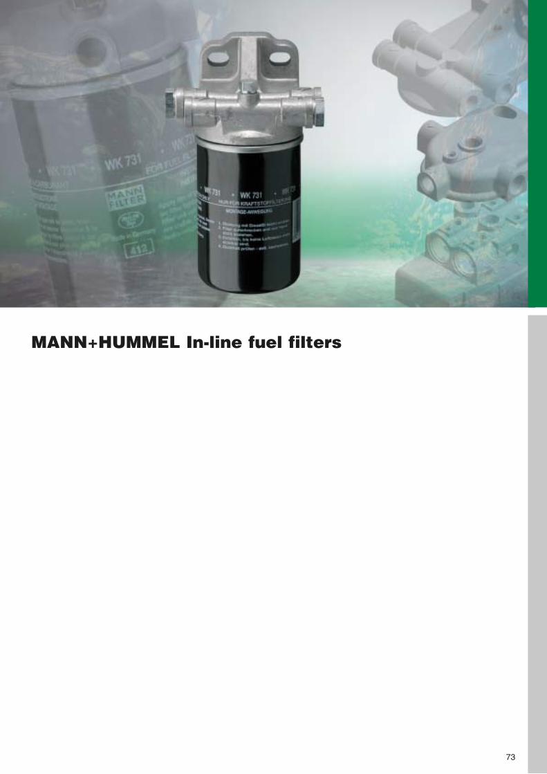
MANN+HUMMEL In-line fuel filters
73
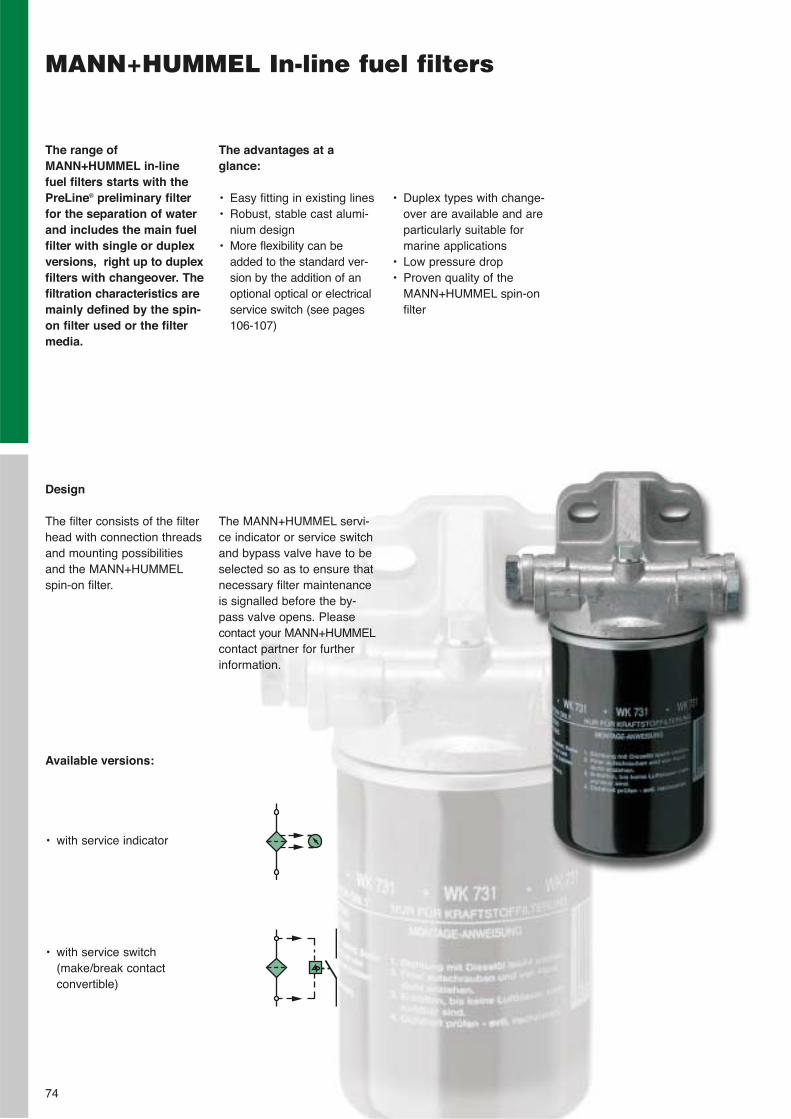
MANN+HUMMEL In-line fuel filters
The advantages at a glance:
• Easy fitting in existing lines• Robust, stable cast alumi-
nium design• More flexibility can be
added to the standard ver-sion by the addition of anoptional optical or electricalservice switch (see pages106-107)
The range of MANN+HUMMEL in-linefuel filters starts with thePreLine® preliminary filterfor the separation of waterand includes the main fuelfilter with single or duplexversions, right up to duplexfilters with changeover. Thefiltration characteristics aremainly defined by the spin-on filter used or the filtermedia.
• Duplex types with change-over are available and areparticularly suitable formarine applications
• Low pressure drop• Proven quality of the
MANN+HUMMEL spin-onfilter
Design
The filter consists of the filterhead with connection threadsand mounting possibilitiesand the MANN+HUMMELspin-on filter.
Available versions:
• with service indicator
• with service switch(make/break contactconvertible)
The MANN+HUMMEL servi-ce indicator or service switchand bypass valve have to beselected so as to ensure thatnecessary filter maintenanceis signalled before the by-pass valve opens. Pleasecontact your MANN+HUMMELcontact partner for furtherinformation.
74
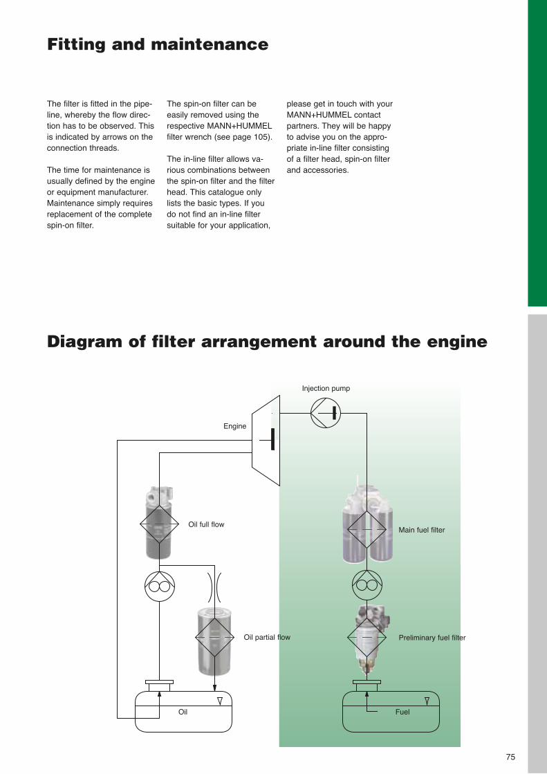
Fitting and maintenance
The filter is fitted in the pipe-line, whereby the flow direc-tion has to be observed. Thisis indicated by arrows on theconnection threads.
The time for maintenance isusually defined by the engineor equipment manufacturer.Maintenance simply requiresreplacement of the completespin-on filter.
The spin-on filter can beeasily removed using the respective MANN+HUMMELfilter wrench (see page 105).
The in-line filter allows va-rious combinations betweenthe spin-on filter and the filterhead. This catalogue onlylists the basic types. If you do not find an in-line filter suitable for your application,
please get in touch with yourMANN+HUMMEL contactpartners. They will be happyto advise you on the appro-priate in-line filter consistingof a filter head, spin-on filterand accessories.
75
Main fuel filter
Preliminary fuel filter
Oil full flow
Oil partial flow
Injection pump
Engine
Oil Fuel
Diagram of filter arrangement around the engine
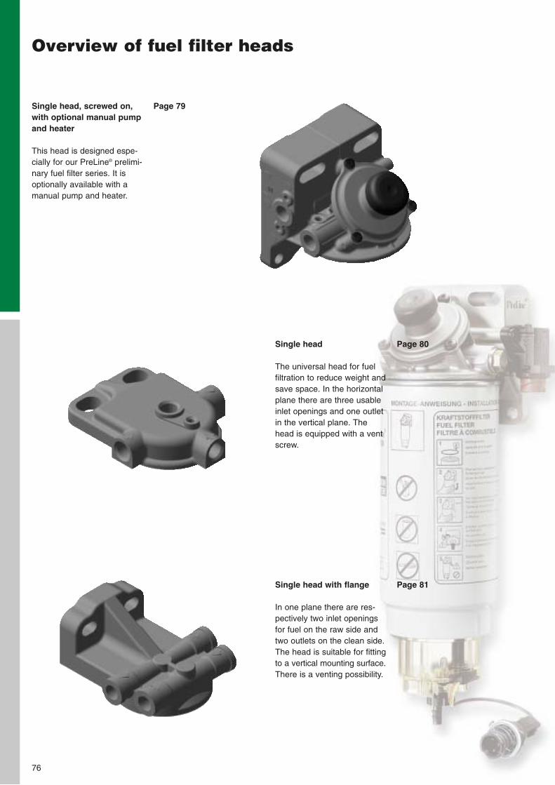
76
Overview of fuel filter heads
Single head, screwed on,with optional manual pumpand heater
This head is designed espe-cially for our PreLine® prelimi-nary fuel filter series. It isoptionally available with amanual pump and heater.
Single head
The universal head for fuelfiltration to reduce weight andsave space. In the horizontalplane there are three usableinlet openings and one outletin the vertical plane. Thehead is equipped with a ventscrew.
Single head with flange
In one plane there are res-pectively two inlet openingsfor fuel on the raw side andtwo outlets on the clean side.The head is suitable for fittingto a vertical mounting surface.There is a venting possibility.
Page 79
Page 80
Page 81
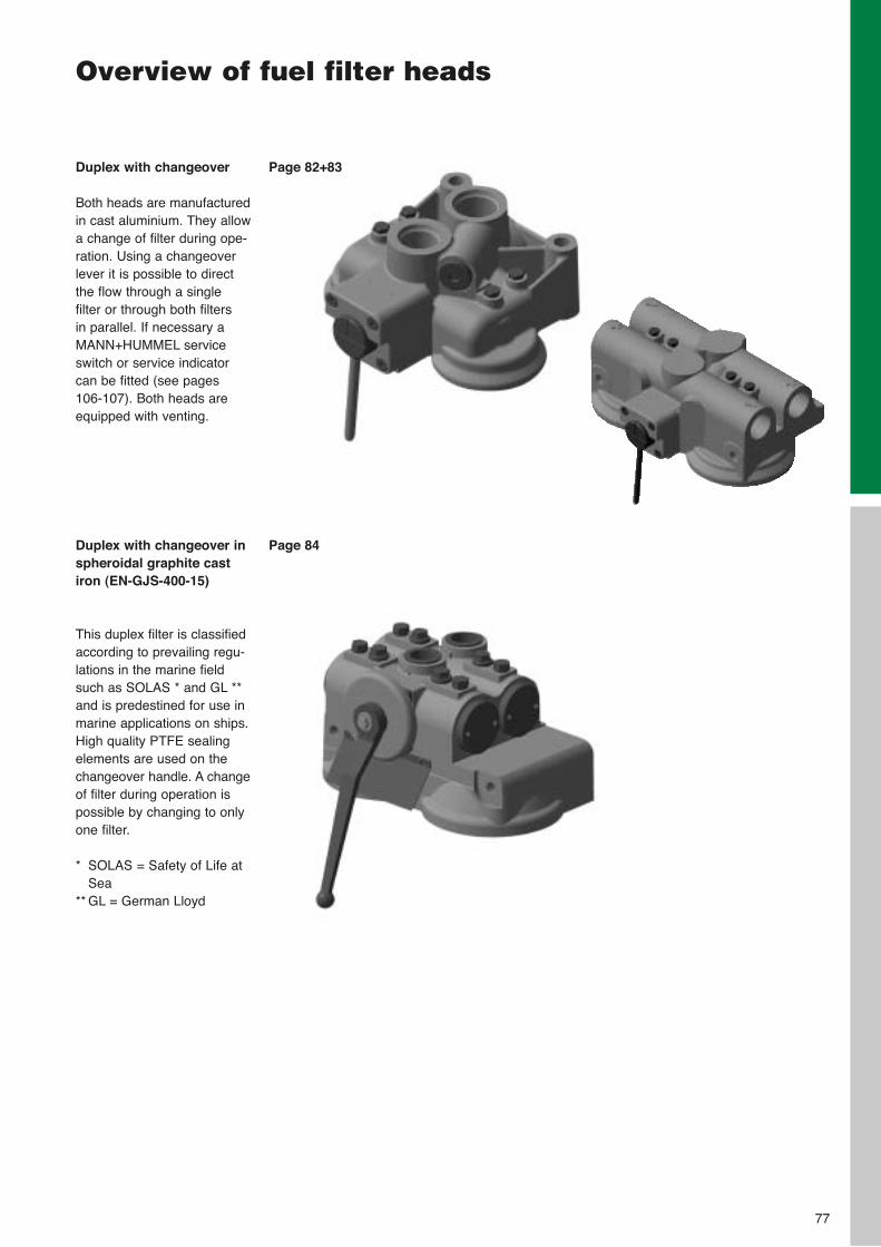
77
Overview of fuel filter heads
Duplex with changeover
Both heads are manufacturedin cast aluminium. They allowa change of filter during ope-ration. Using a changeoverlever it is possible to directthe flow through a single filter or through both filters in parallel. If necessary aMANN+HUMMEL serviceswitch or service indicatorcan be fitted (see pages 106-107). Both heads areequipped with venting.
Duplex with changeover inspheroidal graphite castiron (EN-GJS-400-15)
This duplex filter is classifiedaccording to prevailing regu-lations in the marine fieldsuch as SOLAS * and GL **and is predestined for use inmarine applications on ships.High quality PTFE sealingelements are used on thechangeover handle. A changeof filter during operation ispossible by changing to onlyone filter.
* SOLAS = Safety of Life atSea
** GL = German Lloyd
Page 82+83
Page 84
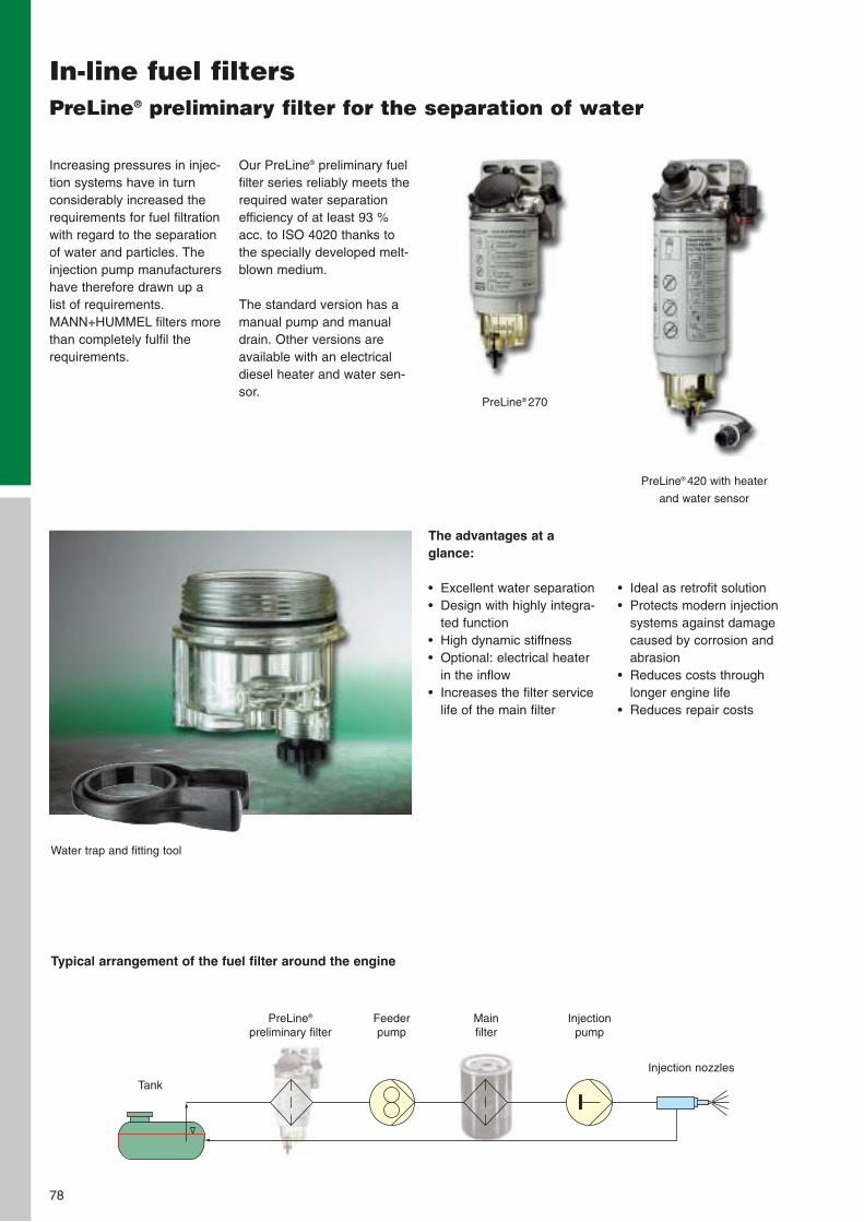
78
In-line fuel filtersPreLine® preliminary filter for the separation of water
Increasing pressures in injec-tion systems have in turnconsiderably increased therequirements for fuel filtrationwith regard to the separationof water and particles. Theinjection pump manufacturershave therefore drawn up alist of requirements.MANN+HUMMEL filters morethan completely fulfil therequirements.
Our PreLine® preliminary fuelfilter series reliably meets therequired water separationefficiency of at least 93 %acc. to ISO 4020 thanks tothe specially developed melt-blown medium.
The standard version has amanual pump and manualdrain. Other versions areavailable with an electricaldiesel heater and water sen-sor.
The advantages at a glance:
• Excellent water separation• Design with highly integra-
ted function• High dynamic stiffness• Optional: electrical heater
in the inflow• Increases the filter service
life of the main filter
• Ideal as retrofit solution• Protects modern injection
systems against damagecaused by corrosion andabrasion
• Reduces costs through longer engine life
• Reduces repair costs
PreLine® 270
PreLine® 420 with heater
and water sensor
Water trap and fitting tool
Typical arrangement of the fuel filter around the engine
Tank
PreLine®
preliminary filterFeeder pump
Main filter
Injection pump
Injection nozzles
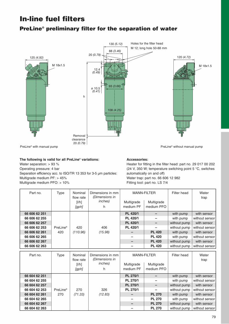
79
In-line fuel filtersPreLine® preliminary filter for the separation of water
Dimensions in mm (Dimensions in
inches)
h
406(15.98)
Nominal flow rate
[l/h][gph]
420(110.96)
ø 10.5(0.41)
125 (4.92)
108 (4.25)
93 (3.66)
20 (0.79)
The following is valid for all PreLine® variations:Water separation: > 93 %Operating pressure: 4 barSeparation efficiency acc. to ISO/TR 13 353 for 3-5 µm particles:Multigrade medium PF: > 45%Multigrade medium PFO: > 10%
130 (5.12)
88 (3.46)
12.4(0.49)
h
Removalclearance 20 (0.79)
Type
PreLine®
420
Part no.
66 606 62 25166 606 62 25566 606 62 25766 606 62 25366 606 62 26166 606 62 26566 606 62 26766 606 62 263
PreLine® with manual pump PreLine® without manual pump
Water trap
with sensorwithout sensor
with sensorwithout sensor
with sensorwithout sensor
with sensorwithout sensor
Filter head
with pumpwith pump
without pumpwithout pump
with pumpwith pump
without pumpwithout pump
MANN-FILTER
Multigrademedium PFO
––––
PL 420PL 420PL 420PL 420
Multigrademedium PF
PL 420/1PL 420/1PL 420/1PL 420/1
––––
Dimensions in mm (Dimensions in
inches)
h
326(12.83)
Nominal flow rate
[l/h][gph]
270(71.33)
Type
PreLine®
270
Part no.
66 604 62 25166 604 62 25566 604 62 25766 604 62 25366 604 62 26166 604 62 26566 604 62 26766 604 62 263
Water trap
with sensorwithout sensor
with sensorwithout sensor
with sensorwithout sensor
with sensorwithout sensor
Filter head
with pumpwith pump
without pumpwithout pump
with pumpwith pump
without pumpwithout pump
MANN-FILTER
Multigrademedium PFO
––––
PL 270PL 270PL 270PL 270
Multigrademedium PF
PL 270/1PL 270/1PL 270/1PL 270/1
––––
Accessories:Heater for fitting in the filter head: part no. 29 017 00 202 (24 V, 350 W; temperature switching point 5 °C, switches automatically on and off)Water trap: part no. 66 606 12 982Fitting tool: part no. LS 7/4
Holes for the filter head
M 12; long hole 50-88 mm
M 18x1.5
120 (4.72)
M 18x1.5
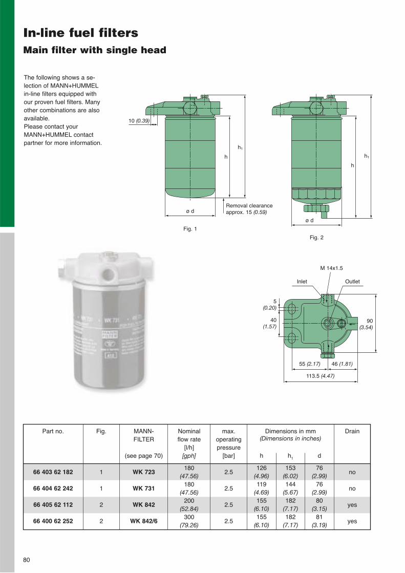
80
In-line fuel filtersMain filter with single head
The following shows a se-lection of MANN+HUMMELin-line filters equipped withour proven fuel filters. Manyother combinations are alsoavailable. Please contact yourMANN+HUMMEL contactpartner for more information.
66 403 62 182
66 404 62 242
66 405 62 112
66 400 62 252
Part no. Dimensions in mm(Dimensions in inches)
h
126(4.96)119
(4.69)155
(6.10)155
(6.10)
h1
153(6.02)144
(5.67)182
(7.17)182
(7.17)
d
76(2.99)
76(2.99)
80(3.15)
81(3.19)
MANN-FILTER
(see page 70)
WK 723
WK 731
WK 842
WK 842/6
Nominal flow rate
[l/h][gph]
180(47.56)
180(47.56)
200(52.84)
300(79.26)
max. operatingpressure
[bar]
2.5
2.5
2.5
2.5
Inlet
Drain
no
no
yes
yes
Fig.
1
1
2
2
h
ø d
10 (0.39)
h1
Removal clearanceapprox. 15 (0.59)
Fig. 1
Fig. 2
h
ø d
h1
Outlet
5(0.20)
40(1.57)
90(3.54)
55 (2.17) 46 (1.81)
113.5 (4.47)
M 14x1.5
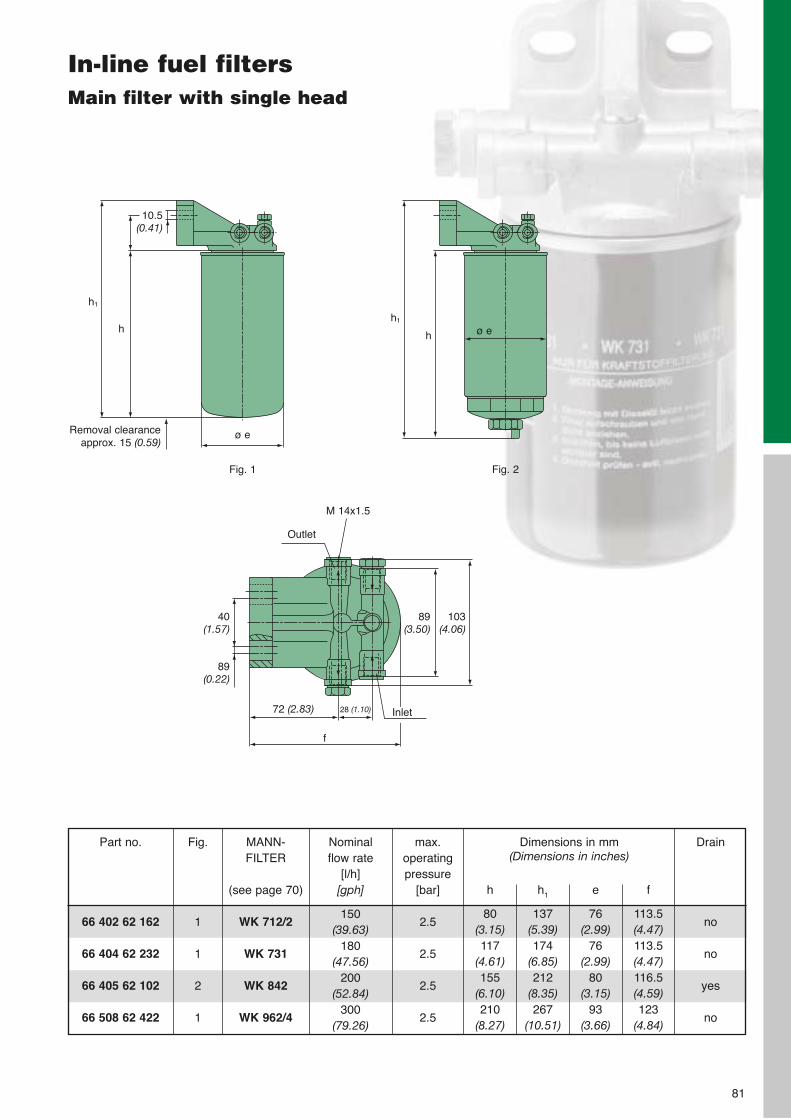
81
In-line fuel filtersMain filter with single head
66 402 62 162
66 404 62 232
66 405 62 102
66 508 62 422
Part no. Dimensions in mm (Dimensions in inches)
h
80(3.15)117
(4.61)155
(6.10)210
(8.27)
h1
137(5.39)174
(6.85)212
(8.35)267
(10.51)
e
76(2.99)
76(2.99)
80(3.15)
93(3.66)
f
113.5(4.47)113.5(4.47)116.5(4.59)123
(4.84)
MANN-FILTER
(see page 70)
WK 712/2
WK 731
WK 842
WK 962/4
Nominal flow rate
[l/h][gph]
150(39.63)
180(47.56)
200(52.84)
300(79.26)
max. operatingpressure
[bar]
2.5
2.5
2.5
2.5
Outlet
89(3.50)
103(4.06)
72 (2.83)
f
28 (1.10) Inlet
h
ø e
10.5 (0.41)
h1
Removal clearanceapprox. 15 (0.59)
Fig. 1
h
h1
Fig. 2
40(1.57)
89(0.22)
Drain
no
no
yes
no
Fig.
1
1
2
1
ø e
M 14x1.5
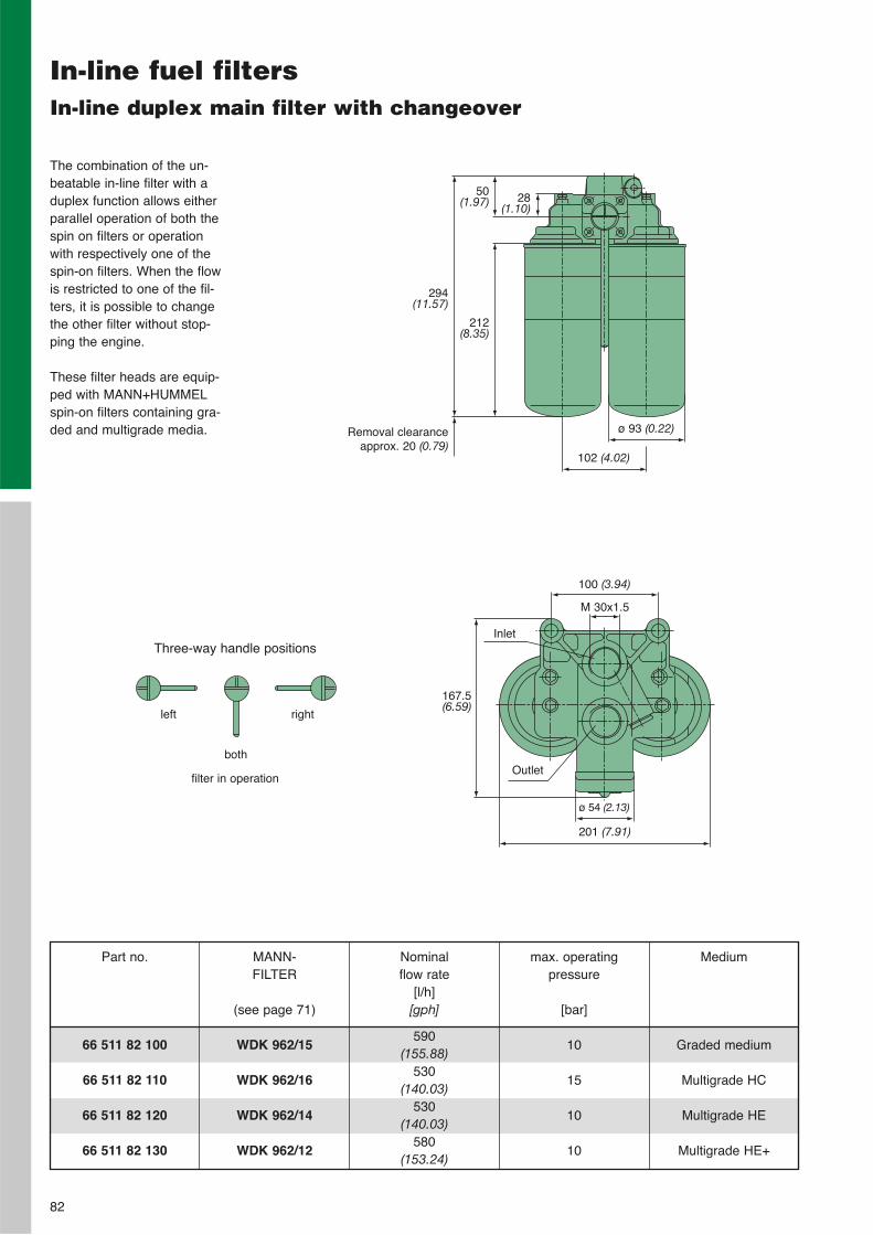
82
In-line fuel filtersIn-line duplex main filter with changeover
The combination of the un-beatable in-line filter with aduplex function allows eitherparallel operation of both thespin on filters or operationwith respectively one of thespin-on filters. When the flowis restricted to one of the fil-ters, it is possible to changethe other filter without stop-ping the engine.
These filter heads are equip-ped with MANN+HUMMELspin-on filters containing gra-ded and multigrade media.
66 511 82 100
66 511 82 110
66 511 82 120
66 511 82 130
Part no. MANN-FILTER
(see page 71)
WDK 962/15
WDK 962/16
WDK 962/14
WDK 962/12
max. operating pressure
[bar]
10
15
10
10
Nominal flow rate
[l/h][gph]
590(155.88)
530(140.03)
530(140.03)
580(153.24)
Medium
Graded medium
Multigrade HC
Multigrade HE
Multigrade HE+
100 (3.94)
167.5(6.59)
M 30x1.5
28(1.10)
Removal clearanceapprox. 20 (0.79)
ø 93 (0.22)
Three-way handle positions
left right
both
filter in operation
102 (4.02)
212(8.35)
294(11.57)
50(1.97)
Outlet
ø 54 (2.13)
Inlet
201 (7.91)
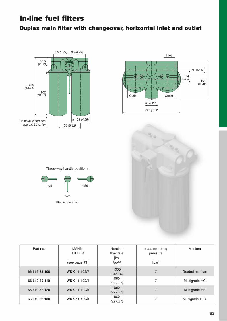
83
In-line fuel filtersDuplex main filter with changeover, horizontal inlet and outlet
66 619 82 100
66 619 82 110
66 619 82 120
66 619 82 130
Part no. MANN-FILTER
(see page 71)
WDK 11 102/7
WDK 11 102/1
WDK 11 102/6
WDK 11 102/3
max. operating pressure
[bar]
7
7
7
7
Nominal flow rate
[l/h][gph]
1000(246.20)
860(227.21)
860(227.21)
860(227.21)
Medium
Graded medium
Multigrade HC
Multigrade HE
Multigrade HE+
Inlet
M 30x1.5
ø 54 (2.13)
Outlet
247 (9.72)
262(10.31)
Removal clearanceapprox. 20 (0.79)
Three-way handle positions
left right
both
filter in operation
54(2.13)
56.5(2.22)
350(13.78)
135 (5.32)
ø 108 (4.25)
95 (3.74) 95 (3.74)
Outlet
164(6.46)
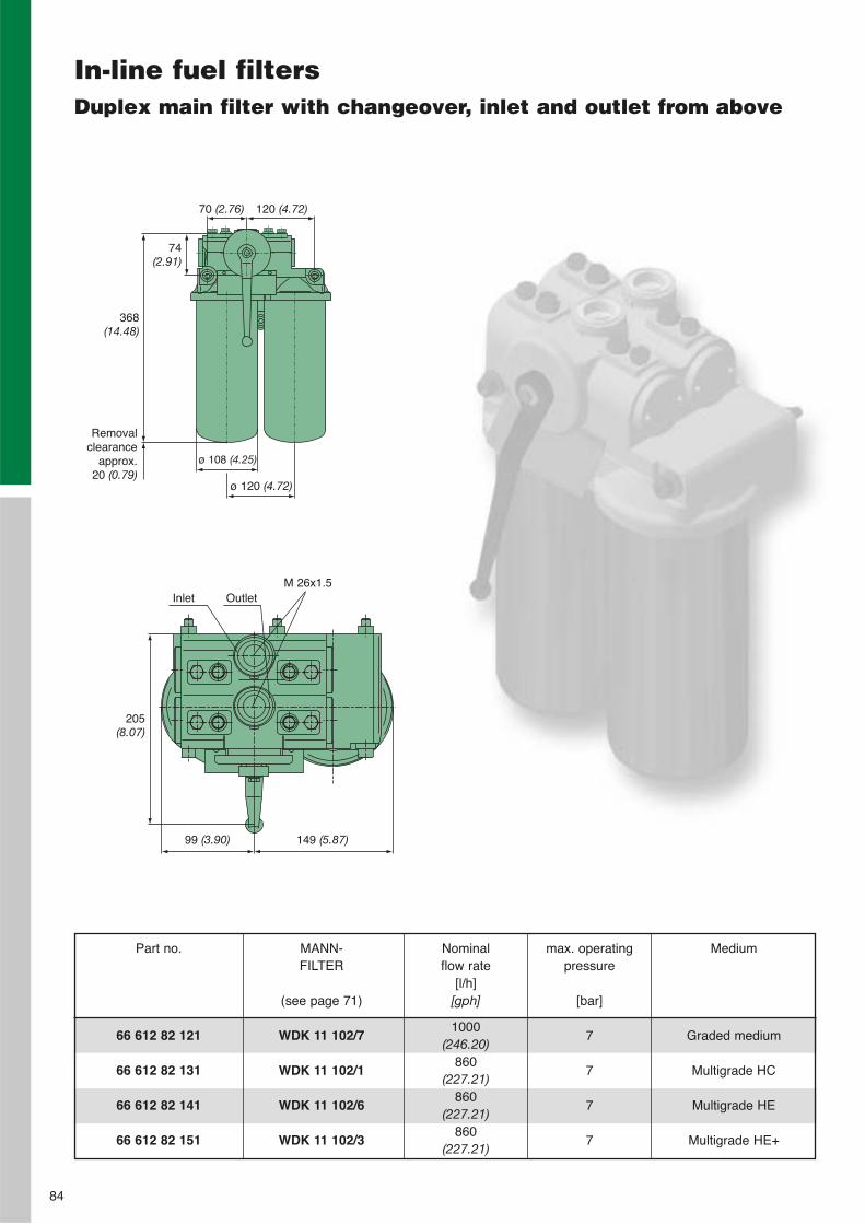
84
In-line fuel filtersDuplex main filter with changeover, inlet and outlet from above
Outlet
99 (3.90)
Inlet
ø 108 (4.25)
74 (2.91)
149 (5.87)
205(8.07)
66 612 82 121
66 612 82 131
66 612 82 141
66 612 82 151
Part no. MANN-FILTER
(see page 71)
WDK 11 102/7
WDK 11 102/1
WDK 11 102/6
WDK 11 102/3
max. operating pressure
[bar]
7
7
7
7
Nominal flow rate
[l/h][gph]
1000(246.20)
860(227.21)
860(227.21)
860(227.21)
Medium
Graded medium
Multigrade HC
Multigrade HE
Multigrade HE+
70 (2.76) 120 (4.72)
368 (14.48)
ø 120 (4.72)
Removalclearance
approx.20 (0.79)
M 26x1.5
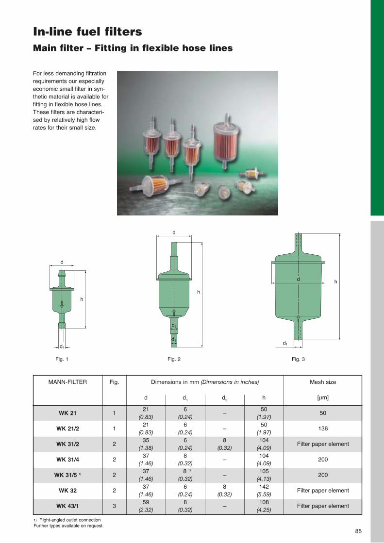
85
In-line fuel filtersMain filter – Fitting in flexible hose lines
For less demanding filtrationrequirements our especiallyeconomic small filter in syn-thetic material is available forfitting in flexible hose lines.These filters are characteri-sed by relatively high flowrates for their small size.
Fig. 1 Fig. 2 Fig. 3
d1
1) Right-angled outlet connectionFurther types available on request.
WK 21
WK 21/2
WK 31/2
WK 31/4
WK 31/5 1)
WK 32
WK 43/1
MANN-FILTER Dimensions in mm (Dimensions in inches)
d
21(0.83)
21(0.83)
35(1.38)
37(1.46)
37(1.46)
37(1.46)
59(2.32)
d1
6(0.24)
6(0.24)
6(0.24)
8(0.32)
8 1)
(0.32)6
(0.24)8
(0.32)
d2
–
–
8(0.32)
–
–
8(0.32)
–
h
50(1.97)
50(1.97)104
(4.09)104
(4.09)105
(4.13)142
(5.59)108
(4.25)
Mesh size
[µm]
50
136
Filter paper element
200
200
Filter paper element
Filter paper element
hh
h
d
d
d
d1
d2
d1
Fig.
1
1
2
2
2
2
3

86
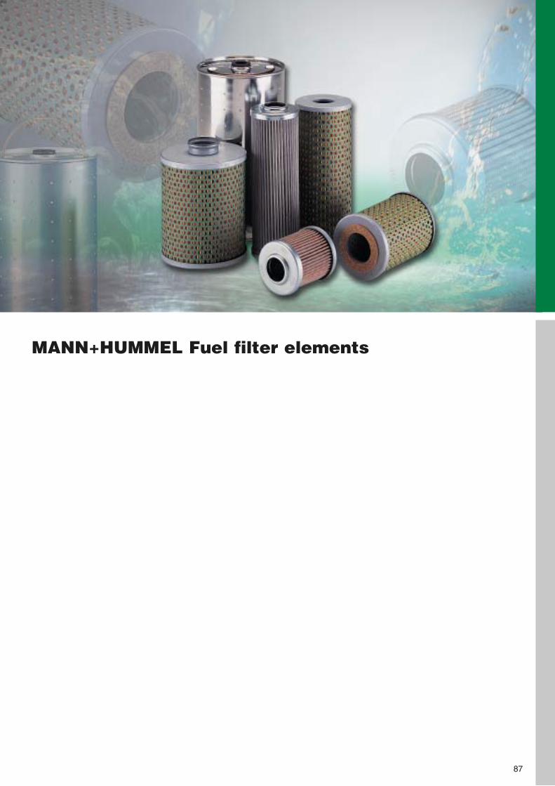
MANN+HUMMEL Fuel filter elements
87
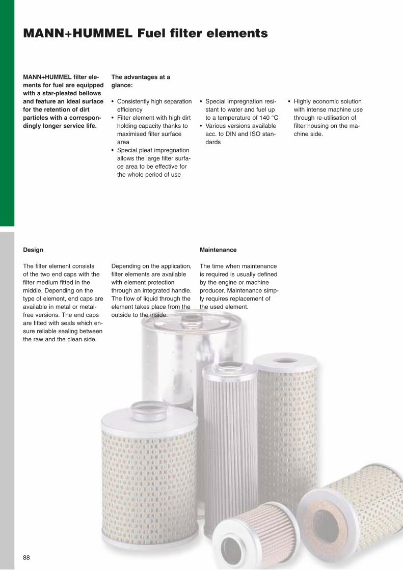
MANN+HUMMEL Fuel filter elements
88
The advantages at a glance:
• Consistently high separationefficiency
• Filter element with high dirtholding capacity thanks tomaximised filter surfacearea
• Special pleat impregnationallows the large filter surfa-ce area to be effective forthe whole period of use
MANN+HUMMEL filter ele-ments for fuel are equippedwith a star-pleated bellowsand feature an ideal surfacefor the retention of dirt particles with a correspon-dingly longer service life.
• Special impregnation resi-stant to water and fuel upto a temperature of 140 °C
• Various versions availableacc. to DIN and ISO stan-dards
• Highly economic solutionwith intense machine usethrough re-utilisation of filter housing on the ma-chine side.
Design
The filter element consists of the two end caps with thefilter medium fitted in themiddle. Depending on thetype of element, end caps areavailable in metal or metal-free versions. The end capsare fitted with seals which en-sure reliable sealing betweenthe raw and the clean side.
Maintenance
The time when maintenanceis required is usually definedby the engine or machineproducer. Maintenance simp-ly requires replacement ofthe used element.
Depending on the application,filter elements are availablewith element protectionthrough an integrated handle.The flow of liquid through theelement takes place from theoutside to the inside.
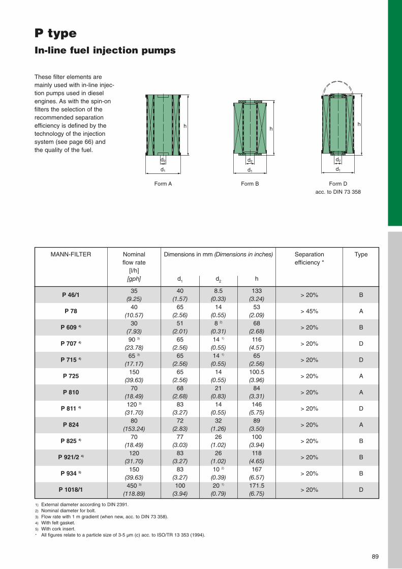
89
Form A Form B Form D
acc. to DIN 73 358
h
d2
d1
h
d2
d1
h
d2
d1
P typeIn-line fuel injection pumps
These filter elements aremainly used with in-line injec-tion pumps used in dieselengines. As with the spin-onfilters the selection of therecommended separationefficiency is defined by thetechnology of the injectionsystem (see page 66) andthe quality of the fuel.
P 46/1
P 78
P 609 4)
P 707 4)
P 715 4)
P 725
P 810
P 811 4)
P 824
P 825 4)
P 921/2 4)
P 934 5)
P 1018/1
MANN-FILTER Dimensions in mm (Dimensions in inches)
d1
40(1.57)
65(2.56)
51(2.01)
65(2.56)
65(2.56)
65(2.56)
68(2.68)
83(3.27)
72(2.83)
77(3.03)
83(3.27)
83(3.27)100
(3.94)
d2
8.5(0.33)
14(0.55)
8 2)
(0.31)14 1)
(0.55)14 1)
(0.55)14
(0.55)21
(0.83)14
(0.55)32
(1.26)26
(1.02)26
(1.02)10 2)
(0.39)20 1)
(0.79)
h
133(3.24)
53(2.09)
68(2.68)116
(4.57)65
(2.56)100.5(3.96)
84(3.31)146
(5.75)89
(3.50)100
(3.94)118
(4.65)167
(6.57)171.5(6.75)
Separation efficiency *
> 20%
> 45%
> 20%
> 20%
> 20%
> 20%
> 20%
> 20%
> 20%
> 20%
> 20%
> 20%
> 20%
Type
B
A
B
D
D
A
A
D
A
B
B
B
D
Nominal flow rate
[l/h][gph]
35(9.25)
40(10.57)
30(7.93)90 3)
(23.78)65 3)
(17.17)150
(39.63)70
(18.49)120 3)
(31.70)80
(153.24)70
(18.49)120
(31.70)150
(39.63)450 3)
(118.89)
1) External diameter according to DIN 2391. 2) Nominal diameter for bolt.3) Flow rate with 1 m gradient (when new, acc. to DIN 73 358).4) With felt gasket.5) With cork insert.* All figures relate to a particle size of 3-5 µm (c) acc. to ISO/TR 13 353 (1994).
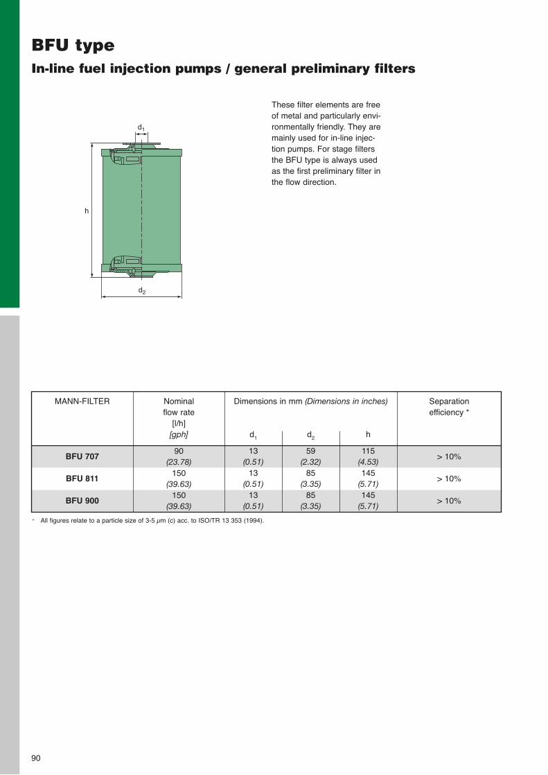
90
BFU typeIn-line fuel injection pumps / general preliminary filters
h
d1
d2
These filter elements are freeof metal and particularly envi-ronmentally friendly. They aremainly used for in-line injec-tion pumps. For stage filtersthe BFU type is always usedas the first preliminary filter inthe flow direction.
BFU 707
BFU 811
BFU 900
MANN-FILTER Dimensions in mm (Dimensions in inches)
d1
13(0.51)
13(0.51)
13(0.51)
d2
59(2.32)
85(3.35)
85(3.35)
h
115(4.53)145
(5.71)145
(5.71)
Separation efficiency *
> 10%
> 10%
> 10%
Nominal flow rate
[l/h][gph]
90(23.78)
150(39.63)
150(39.63)
* All figures relate to a particle size of 3-5 µm (c) acc. to ISO/TR 13 353 (1994).
MANN+HUMMEL Gap-type filters
91
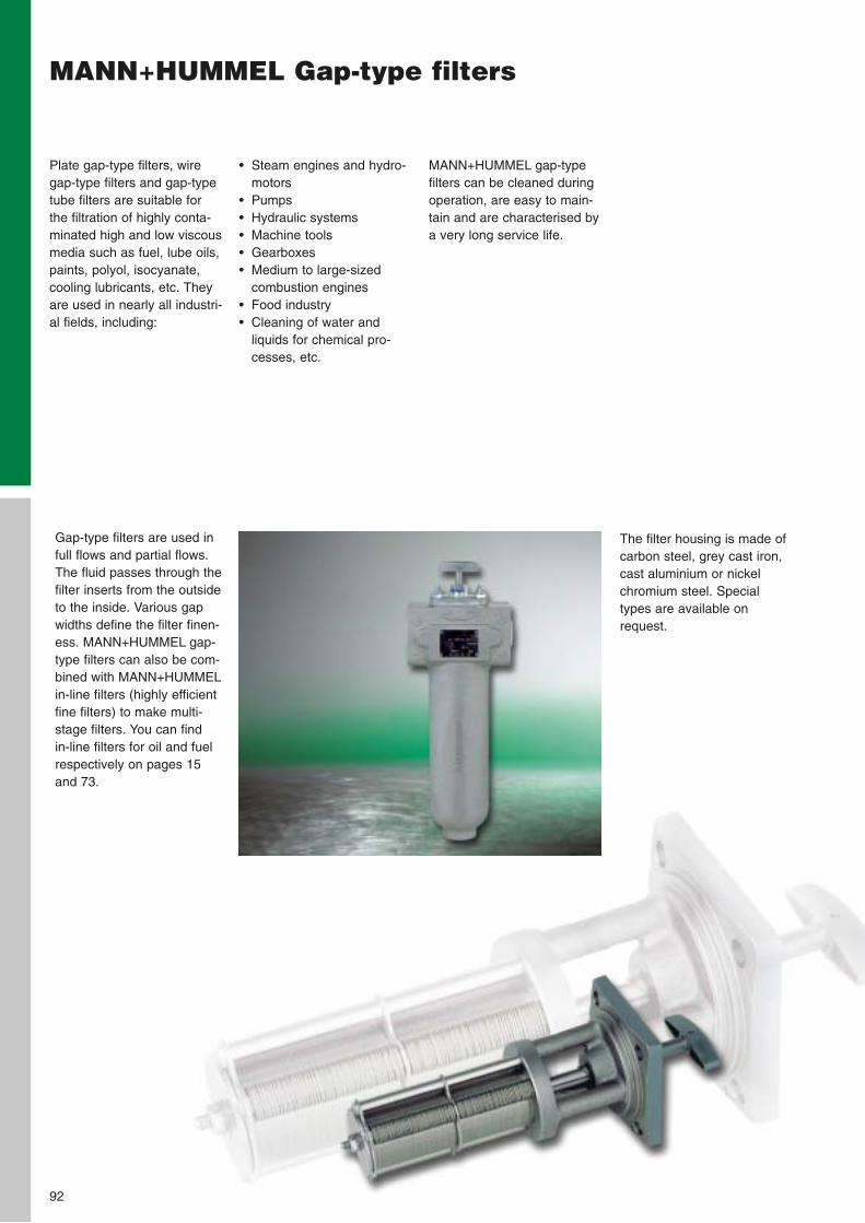
92
MANN+HUMMEL Gap-type filters
• Steam engines and hydro-motors
• Pumps• Hydraulic systems• Machine tools• Gearboxes• Medium to large-sized
combustion engines• Food industry• Cleaning of water and
liquids for chemical pro-cesses, etc.
Plate gap-type filters, wiregap-type filters and gap-typetube filters are suitable forthe filtration of highly conta-minated high and low viscousmedia such as fuel, lube oils,paints, polyol, isocyanate,cooling lubricants, etc. Theyare used in nearly all industri-al fields, including:
MANN+HUMMEL gap-typefilters can be cleaned duringoperation, are easy to main-tain and are characterised bya very long service life.
Gap-type filters are used infull flows and partial flows.The fluid passes through thefilter inserts from the outsideto the inside. Various gapwidths define the filter finen-ess. MANN+HUMMEL gap-type filters can also be com-bined with MANN+HUMMELin-line filters (highly efficientfine filters) to make multi-stage filters. You can find in-line filters for oil and fuelrespectively on pages 15and 73.
The filter housing is made ofcarbon steel, grey cast iron,cast aluminium or nickelchromium steel. Specialtypes are available onrequest.
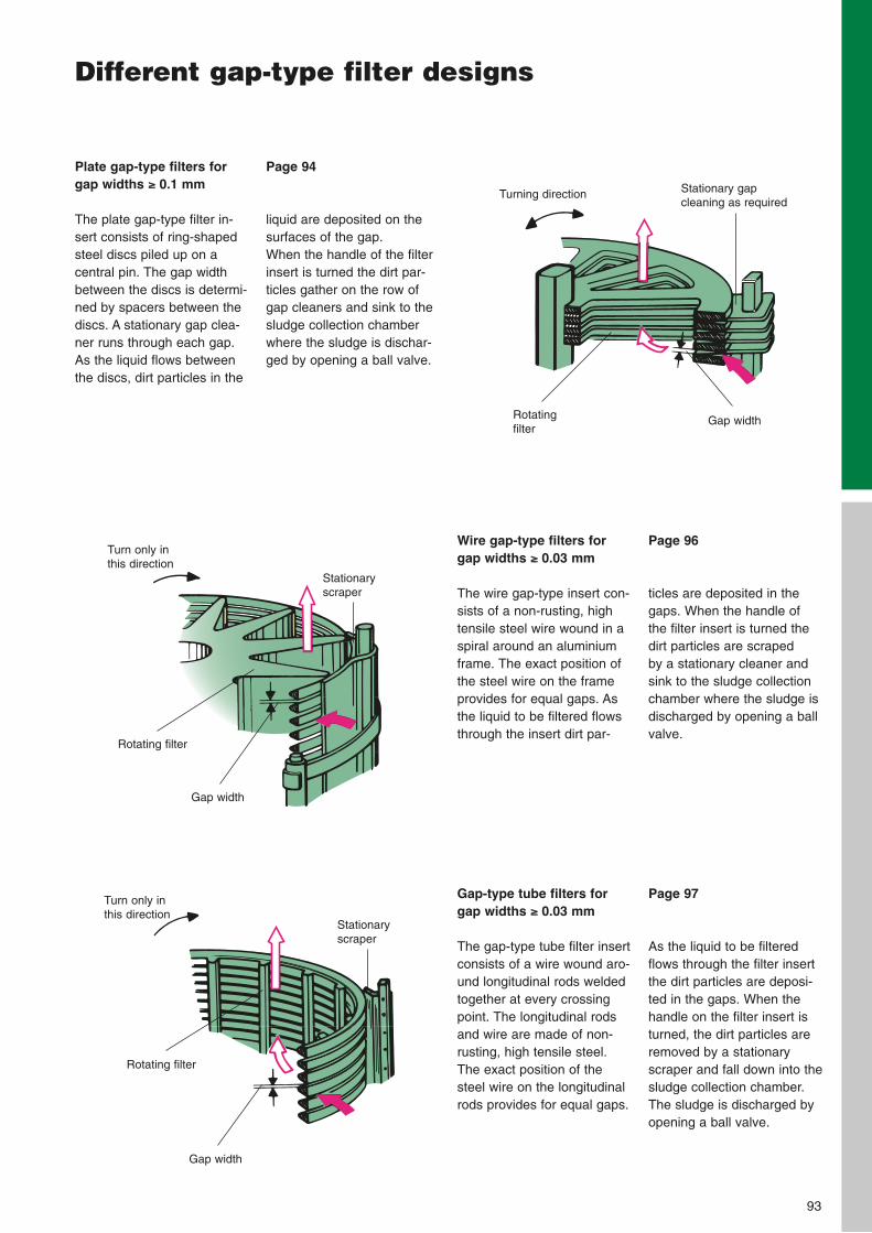
93
Different gap-type filter designs
Page 94
liquid are deposited on thesurfaces of the gap.When the handle of the filterinsert is turned the dirt par-ticles gather on the row ofgap cleaners and sink to thesludge collection chamberwhere the sludge is dischar-ged by opening a ball valve.
Plate gap-type filters forgap widths ≥≥ 0.1 mm
The plate gap-type filter in-sert consists of ring-shapedsteel discs piled up on a central pin. The gap widthbetween the discs is determi-ned by spacers between thediscs. A stationary gap clea-ner runs through each gap.As the liquid flows betweenthe discs, dirt particles in the
Page 96
ticles are deposited in thegaps. When the handle of the filter insert is turned thedirt particles are scraped by a stationary cleaner andsink to the sludge collectionchamber where the sludge isdischarged by opening a ballvalve.
Wire gap-type filters forgap widths ≥≥ 0.03 mm
The wire gap-type insert con-sists of a non-rusting, hightensile steel wire wound in aspiral around an aluminiumframe. The exact position ofthe steel wire on the frameprovides for equal gaps. Asthe liquid to be filtered flowsthrough the insert dirt par-
Page 97
As the liquid to be filteredflows through the filter insertthe dirt particles are deposi-ted in the gaps. When thehandle on the filter insert isturned, the dirt particles areremoved by a stationaryscraper and fall down into thesludge collection chamber.The sludge is discharged byopening a ball valve.
Gap-type tube filters forgap widths ≥≥ 0.03 mm
The gap-type tube filter insertconsists of a wire wound aro-und longitudinal rods weldedtogether at every crossingpoint. The longitudinal rodsand wire are made of non-rusting, high tensile steel.The exact position of thesteel wire on the longitudinalrods provides for equal gaps.
Turning direction Stationary gap cleaning as required
Rotating filter
Turn only inthis direction
Stationaryscraper
Rotating filter
Gap width
Gap width
Turn only inthis direction
Stationaryscraper
Gap width
Rotating filter
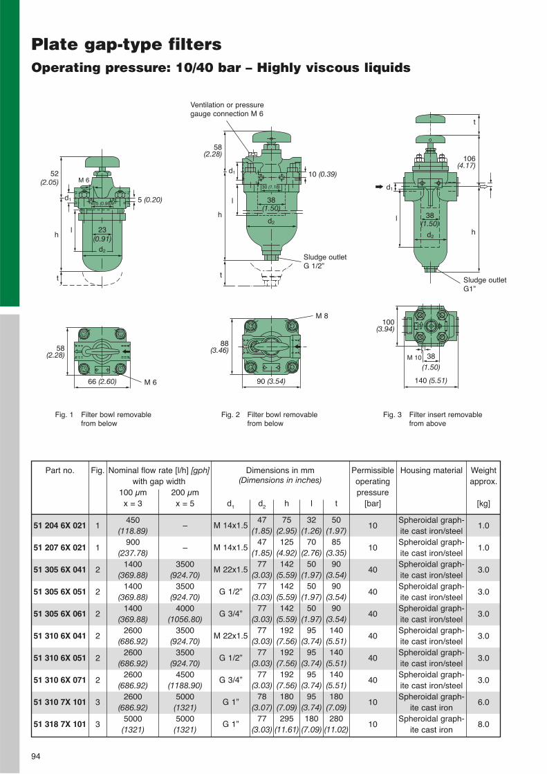
94
Plate gap-type filtersOperating pressure: 10/40 bar – Highly viscous liquids
51 204 6X 021
51 207 6X 021
51 305 6X 041
51 305 6X 051
51 305 6X 061
51 310 6X 041
51 310 6X 051
51 310 6X 071
51 310 7X 101
51 318 7X 101
Part no. Dimensions in mm (Dimensions in inches)
d1
M 14x1.5
M 14x1.5
M 22x1.5
G 1/2”
G 3/4”
M 22x1.5
G 1/2”
G 3/4”
G 1”
G 1”
d2
47(1.85)
47(1.85)
77(3.03)
77(3.03)
77(3.03)
77(3.03)
77(3.03)
77(3.03)
78(3.07)
77(3.03)
h
75(2.95)125
(4.92)142
(5.59)142
(5.59)142
(5.59)192
(7.56)192
(7.56)192
(7.56)180
(7.09)295
(11.61)
l
32(1.26)
70(2.76)
50(1.97)
50(1.97)
50(1.97)
95(3.74)
95(3.74)
95(3.74)
95(3.74)180
(7.09)
t
50(1.97)
85(3.35)
90(3.54)
90(3.54)
90(3.54)140
(5.51)140
(5.51)140
(5.51)180
(7.09)280
(11.02)
Weightapprox.
[kg]
1.0
1.0
3.0
3.0
3.0
3.0
3.0
3.0
6.0
8.0
Nominal flow rate [l/h] [gph] with gap width
Fig. 1 Filter bowl removablefrom below
Fig. 2 Filter bowl removablefrom below
Fig. 3 Filter insert removablefrom above
d2
Sludge outletG 1/2”
Ventilation or pressuregauge connection M 6
52(2.05)
58(2.28)
66 (2.60)
88(3.46)
90 (3.54)
100(3.94)
140 (5.51)
38
(1.50)M 10
23(0.91)
5 (0.20)
M 6
d125 (0.98)
lh
t Sludge outletG1”
58(2.28)
h
t
d1
l
30 (1.18)
38(1.50)
d2
10 (0.39)
t
h
106(4.17)
l
d2
38(1.50)
d1
Fig.
1
1
2
2
2
2
2
2
3
3
Permissibleoperatingpressure
[bar]
10
10
40
40
40
40
40
40
10
10
100 µmx = 3
450(118.89)
900(237.78)
1400(369.88)
1400(369.88)
1400(369.88)
2600(686.92)
2600(686.92)
2600(686.92)
2600(686.92)
5000(1321)
200 µmx = 5
–
–
3500(924.70)
3500(924.70)
4000(1056.80)
3500(924.70)
3500(924.70)
4500(1188.90)
5000(1321)5000(1321)
M 6
M 8
Housing material
Spheroidal graph-ite cast iron/steelSpheroidal graph-ite cast iron/steelSpheroidal graph-ite cast iron/steelSpheroidal graph-ite cast iron/steelSpheroidal graph-ite cast iron/steelSpheroidal graph-ite cast iron/steelSpheroidal graph-ite cast iron/steelSpheroidal graph-ite cast iron/steelSpheroidal graph-
ite cast ironSpheroidal graph-
ite cast iron
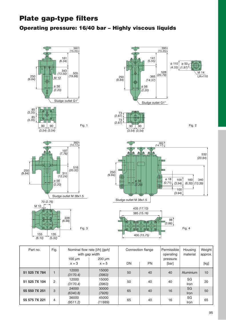
95
51 525 7X 784
51 525 7X 10⁴
55 550 7X 251
55 575 7X 221
Part no. Weightapprox.
[kg]
10
20
50
65
Nominal flow rate [l/h] [gph] with gap width
Fig.
1
2
3
4
Permissibleoperatingpressure
[bar]
40
40
16
16
Housingmaterial
Aluminium
SGIronSGIronSGIron
100 µmx = 3
12000(3170.4)12000
(3170.4)24000
(6340.8)36000
(9511.2)
200 µmx = 5
15000(3963)15000(3963)30000(7926)45000(11889)
Connection flange
DN
50
50
65
65
PN
40
40
40
40
Plate gap-type filtersOperating pressure: 16/40 bar – Highly viscous liquids
Fig. 1
Sludge outlet G1”
250(9.84)
343(13.50) 505
(19.88)
390(15.35)
161(6.34)
M 12
ø 56(2.20)
85(3.35)
85(3.35)
90
(3.54)
90
(3.54)
Fig. 2
Sludge outlet G1”
250(9.84)
365(14.37)
528(20.79)
390(15.35)
141(5.55)
ø 56(2.20)
ø 110(4.33)
ø 50(1.97)
M 14LK=110
73(2.87)
73(2.87)
90
(3.54)
90
(3.54)
Fig. 3
155(6.10)
135(5.32)
228(8.98)
70 (2.76)M 10
Sludge outlet M 38x1.5
250(9.84) 311
(12.24)
516(20.32)
360(14.17)
197(7.76)
ø 56(2.20)
Fig. 4
Sludge outlet M 38x1.5
250(9.84)
532(20.94)
360(14.17)
ø 56(2.20)
100(3.94)
ø 18(0.71)
100(3.94)
160(6.30)
340(13.39)
435 (17.13)
385 (15.16)
400 (15.75)
98(3.86)
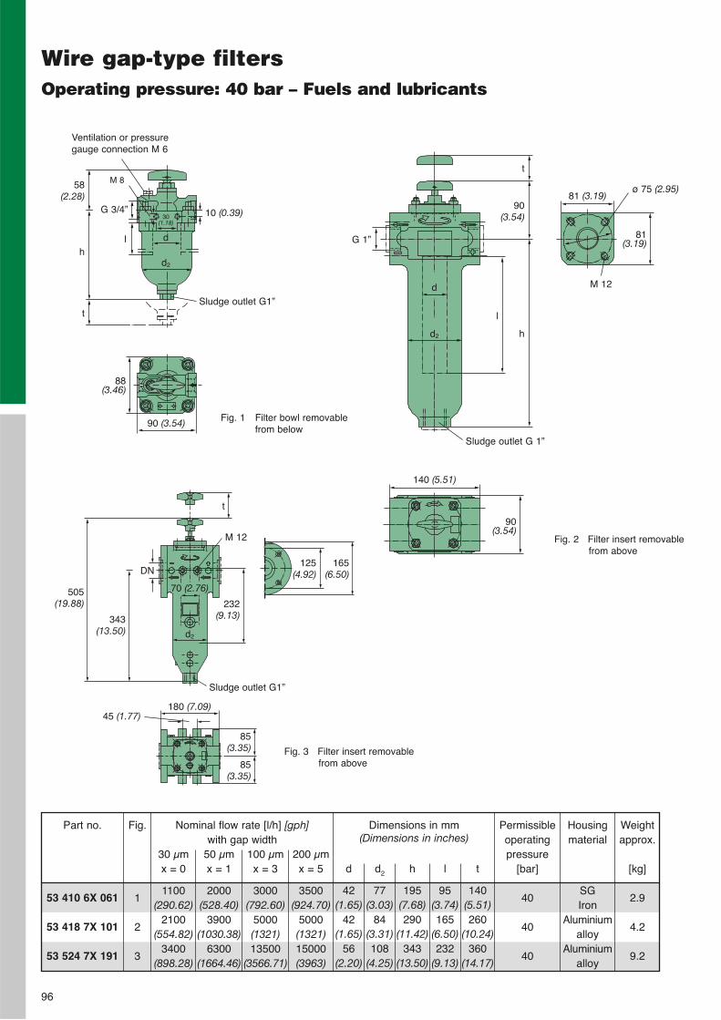
53 410 6X 061
53 418 7X 101
53 524 7X 191
Part no. Weightapprox.
[kg]
2.9
4.2
9.2
Fig.
1
2
3
Permissibleoperatingpressure
[bar]
40
40
40
Housingmaterial
SGIron
Aluminiumalloy
Aluminiumalloy
30 µmx = 0
1100(290.62)
2100(554.82)
3400(898.28)
50 µmx = 1
2000(528.40)
3900(1030.38)
6300(1664.46)
100 µmx = 3
3000(792.60)
5000(1321)13500
(3566.71)
200 µmx = 5
3500(924.70)
5000(1321)15000(3963)
Wire gap-type filtersOperating pressure: 40 bar – Fuels and lubricants
Dimensions in mm (Dimensions in inches)
d
42(1.65)
42(1.65)
56(2.20)
d2
77(3.03)
84(3.31)108
(4.25)
h
195(7.68)290
(11.42)343
(13.50)
l
95(3.74)165
(6.50)232
(9.13)
t
140(5.51)260
(10.24)360
(14.17)
Nominal flow rate [l/h] [gph] with gap width
96
Fig. 1 Filter bowl removablefrom below
Fig. 2 Filter insert removablefrom above
d2
58(2.28)
88(3.46)
90 (3.54)
d
10 (0.39)
M 8
G 3/4”30
(1.18)
lh
tSludge outlet G1”
Ventilation or pressuregauge connection M 6
Sludge outlet G 1”
81(3.19)
81 (3.19)
90(3.54)
140 (5.51)
90(3.54)
t
h
l
d2
d
G 1”
ø 75 (2.95)
M 12
Fig. 3 Filter insert removablefrom above
505(19.88)
343(13.50)
t
232(9.13)
125(4.92)
165(6.50)DN
d2
70 (2.76)
Sludge outlet G1”
85(3.35)
85(3.35)
180 (7.09)
M 12
45 (1.77)
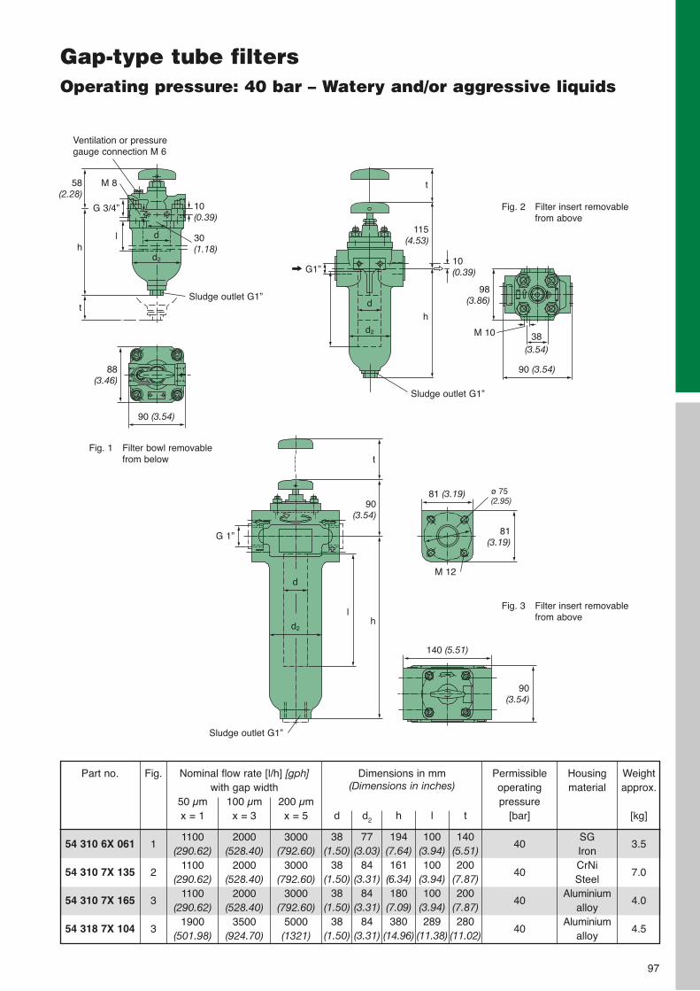
54 310 6X 061
54 310 7X 135
54 310 7X 165
54 318 7X 10⁴
Part no. Weightapprox.
[kg]
3.5
7.0
4.0
4.5
Nominal flow rate [l/h] [gph] with gap width
Fig.
1
2
3
3
Permissibleoperating pressure
[bar]
40
40
40
40
50 µmx = 1
1100(290.62)
1100(290.62)
1100(290.62)
1900(501.98)
100 µmx = 3
2000(528.40)
2000(528.40)
2000(528.40)
3500(924.70)
200 µmx = 5
3000(792.60)
3000(792.60)
3000(792.60)
5000(1321)
Gap-type tube filtersOperating pressure: 40 bar – Watery and/or aggressive liquids
97
Dimensions in mm (Dimensions in inches)
d
38(1.50)
38(1.50)
38(1.50)
38(1.50)
d2
77(3.03)
84(3.31)
84(3.31)
84(3.31)
h
194(7.64)161
(6.34)180
(7.09)380
(14.96)
l
100(3.94)100
(3.94)100
(3.94)289
(11.38)
t
140(5.51)200
(7.87)200
(7.87)280
(11.02)
Fig. 1 Filter bowl removablefrom below
Fig. 3 Filter insert removablefrom above
Fig. 2 Filter insert removablefrom above
Sludge outlet G1”
G 3/4”
lh
t
58(2.28)
M 8
Ventilation or pressuregauge connection M 6
10(0.39)
30(1.18)
d2
d
90 (3.54)
88(3.46)
t
h
115(4.53)
10(0.39)
d2
G1”
d
Sludge outlet G1”
M 10
98(3.86)
90 (3.54)
38 (3.54)
t
h
90(3.54)
G 1”
l
d
d2
Sludge outlet G1”
81 (3.19)
M 12
81(3.19)
ø 75(2.95)
140 (5.51)
90(3.54)
Housingmaterial
SGIronCrNiSteel
Aluminiumalloy
Aluminiumalloy

98
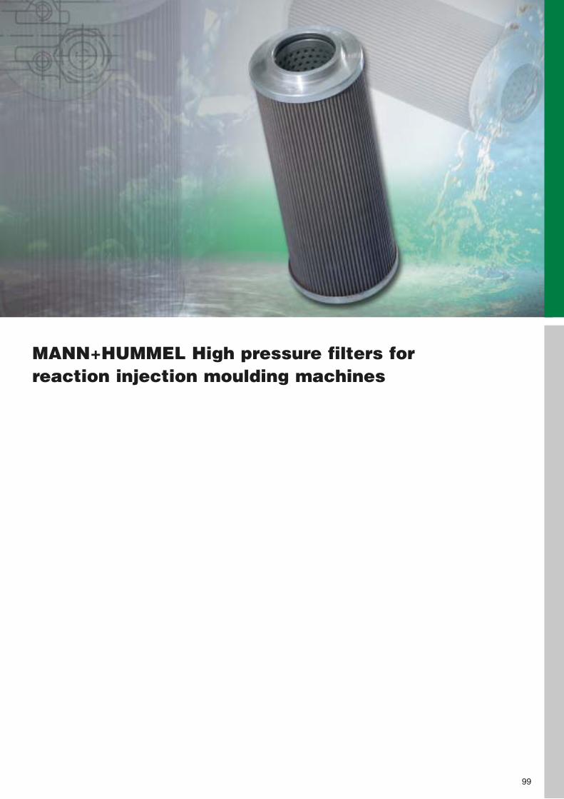
MANN+HUMMEL High pressure filters forreaction injection moulding machines
99
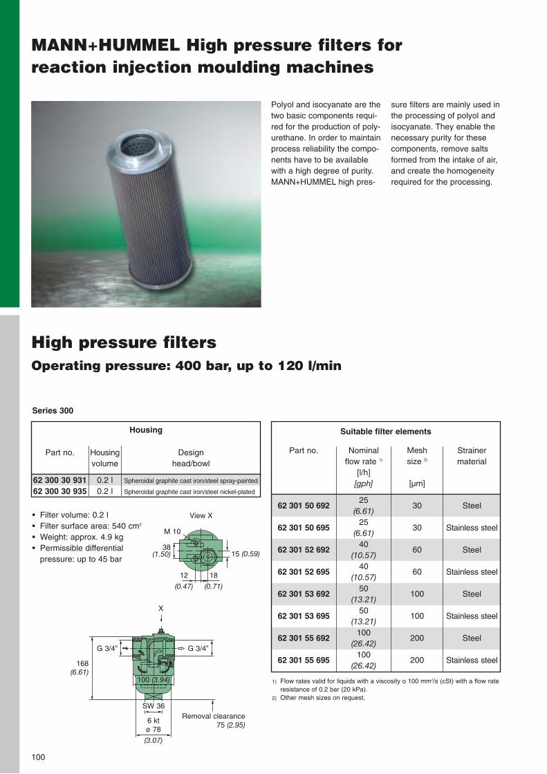
100
MANN+HUMMEL High pressure filters forreaction injection moulding machines
sure filters are mainly used inthe processing of polyol andisocyanate. They enable thenecessary purity for thesecomponents, remove saltsformed from the intake of air,and create the homogeneityrequired for the processing.
Polyol and isocyanate are thetwo basic components requi-red for the production of poly-urethane. In order to maintainprocess reliability the compo-nents have to be availablewith a high degree of purity.MANN+HUMMEL high pres-
High pressure filtersOperating pressure: 400 bar, up to 120 l/min
• Filter volume: 0.2 l• Filter surface area: 540 cm2
• Weight: approx. 4.9 kg• Permissible differential
pressure: up to 45 bar
Suitable filter elements
Part no.
62 300 30 93162 300 30 935
Design head/bowl
Spheroidal graphite cast iron/steel spray-painted
Spheroidal graphite cast iron/steel nickel-plated
Housingvolume
0.2 l0.2 l
Housing
Series 300
168(6.61)
38(1.50)
18
(0.71)
SW 36
15 (0.59)
12
(0.47)
View X
6 ktø 78
(3.07)
Removal clearance75 (2.95)
100 (3.94)
G 3/4”G 3/4”
X
62 301 50 692
62 301 50 695
62 301 52 692
62 301 52 695
62 301 53 692
62 301 53 695
62 301 55 692
62 301 55 695
Part no. Nominal flow rate 1)
[l/h][gph]
25(6.61)
25(6.61)
40(10.57)
40(10.57)
50(13.21)
50(13.21)
100(26.42)
100(26.42)
Mesh size 2)
[µm]
30
30
60
60
100
100
200
200
Strainer material
Steel
Stainless steel
Steel
Stainless steel
Steel
Stainless steel
Steel
Stainless steel
1) Flow rates valid for liquids with a viscosity o 100 mm2/s (cSt) with a flow rateresistance of 0.2 bar (20 kPa).
2) Other mesh sizes on request.
M 10
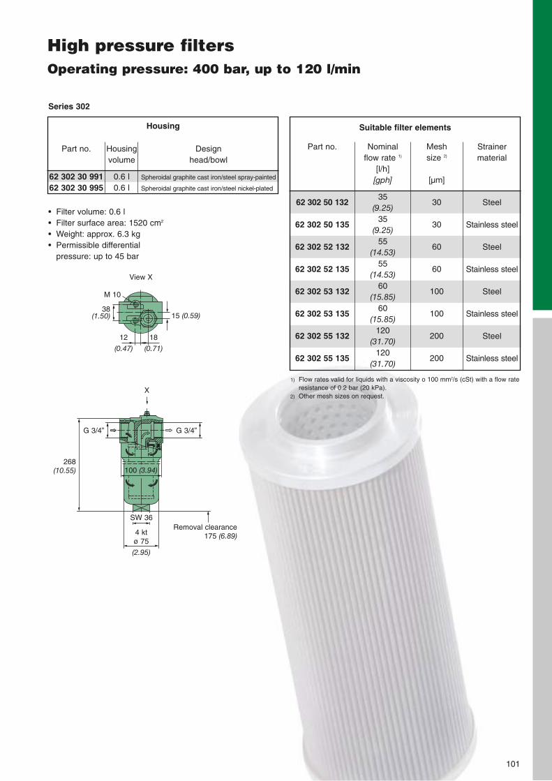
101
High pressure filtersOperating pressure: 400 bar, up to 120 l/min
Part no.
62 302 30 99162 302 30 995
Design head/bowl
Spheroidal graphite cast iron/steel spray-painted
Spheroidal graphite cast iron/steel nickel-plated
Housing volume
0.6 l0.6 l
Housing
Series 302
Suitable filter elements
62 302 50 132
62 302 50 135
62 302 52 132
62 302 52 135
62 302 53 132
62 302 53 135
62 302 55 132
62 302 55 135
Part no. Nominal flow rate 1)
[l/h][gph]
35(9.25)
35(9.25)
55(14.53)
55(14.53)
60(15.85)
60(15.85)
120(31.70)
120(31.70)
Mesh size 2)
[µm]
30
30
60
60
100
100
200
200
Strainer material
Steel
Stainless steel
Steel
Stainless steel
Steel
Stainless steel
Steel
Stainless steel
1) Flow rates valid for liquids with a viscosity o 100 mm2/s (cSt) with a flow rateresistance of 0.2 bar (20 kPa).
2) Other mesh sizes on request.
• Filter volume: 0.6 l• Filter surface area: 1520 cm2
• Weight: approx. 6.3 kg• Permissible differential
pressure: up to 45 bar
38(1.50)
18
(0.71)
15 (0.59)
12
(0.47)
View X
268(10.55)
SW 36
4 ktø 75
(2.95)
Removal clearance 175 (6.89)
100 (3.94)
G 3/4”G 3/4”
X
M 10

102
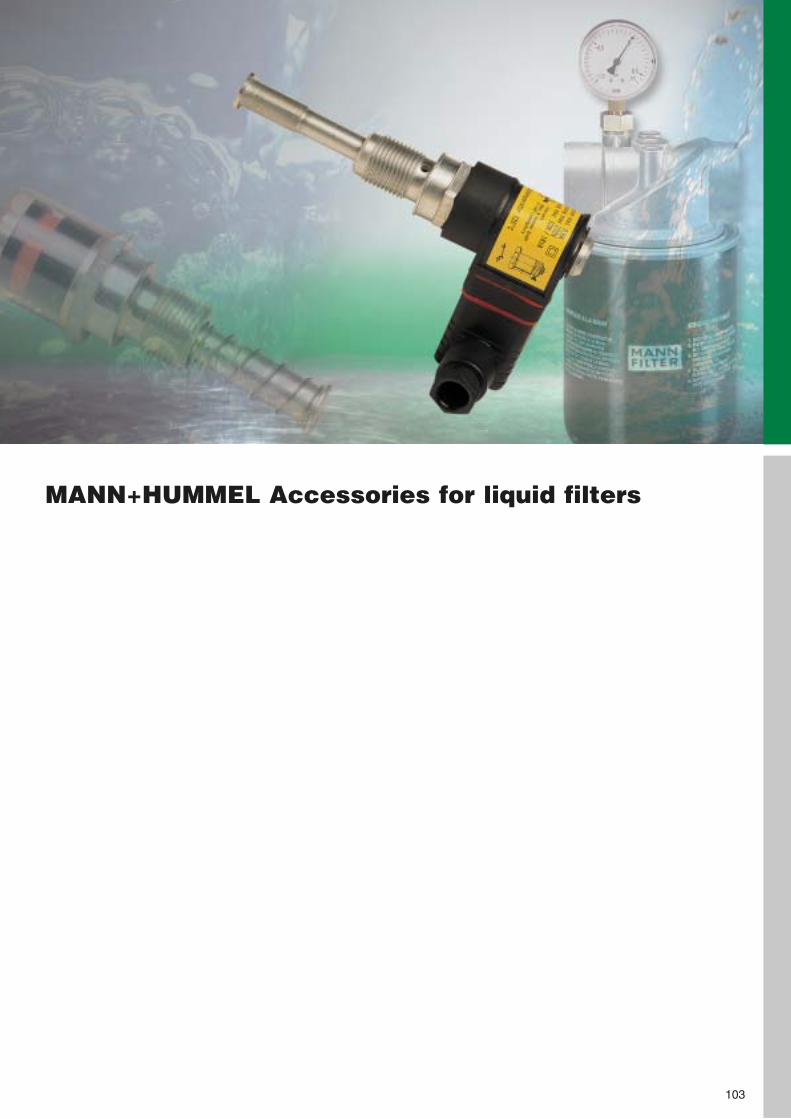
MANN+HUMMEL Accessories for liquid filters
103
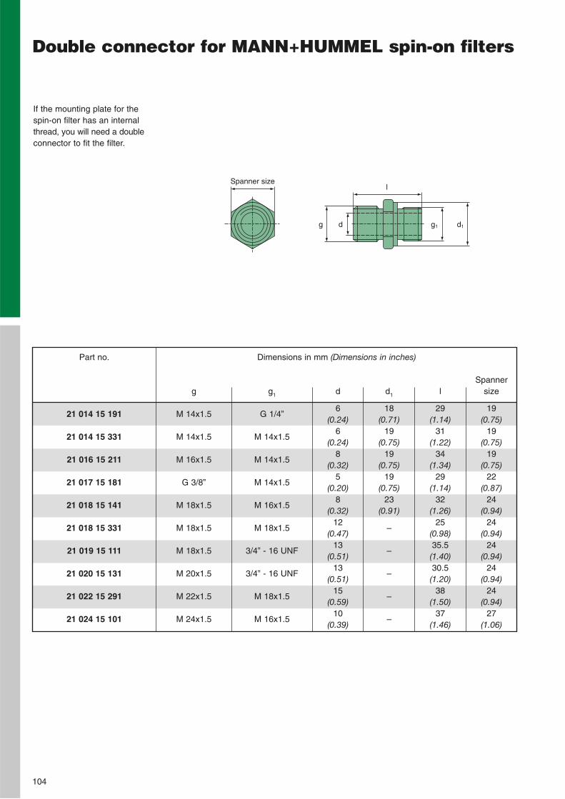
104
Double connector for MANN+HUMMEL spin-on filters
If the mounting plate for thespin-on filter has an internalthread, you will need a doubleconnector to fit the filter.
21 014 15 191
21 014 15 331
21 016 15 211
21 017 15 181
21 018 15 141
21 018 15 331
21 019 15 111
21 020 15 131
21 022 15 291
21 024 15 101
Part no. Dimensions in mm (Dimensions in inches)
g
M 14x1.5
M 14x1.5
M 16x1.5
G 3/8”
M 18x1.5
M 18x1.5
M 18x1.5
M 20x1.5
M 22x1.5
M 24x1.5
g1
G 1/4”
M 14x1.5
M 14x1.5
M 14x1.5
M 16x1.5
M 18x1.5
3/4” - 16 UNF
3/4” - 16 UNF
M 18x1.5
M 16x1.5
d
6(0.24)
6(0.24)
8(0.32)
5(0.20)
8(0.32)
12(0.47)
13(0.51)
13(0.51)
15(0.59)
10(0.39)
d1
18(0.71)
19(0.75)
19(0.75)
19(0.75)
23(0.91)
–
–
–
–
–
l
29(1.14)
31(1.22)
34(1.34)
29(1.14)
32(1.26)
25(0.98)35.5(1.40)30.5(1.20)
38(1.50)
37(1.46)
Spannersize
19(0.75)
19(0.75)
19(0.75)
22(0.87)
24(0.94)
24(0.94)
24(0.94)
24(0.94)
24(0.94)
27(1.06)
Spanner sizel
d1g1dg
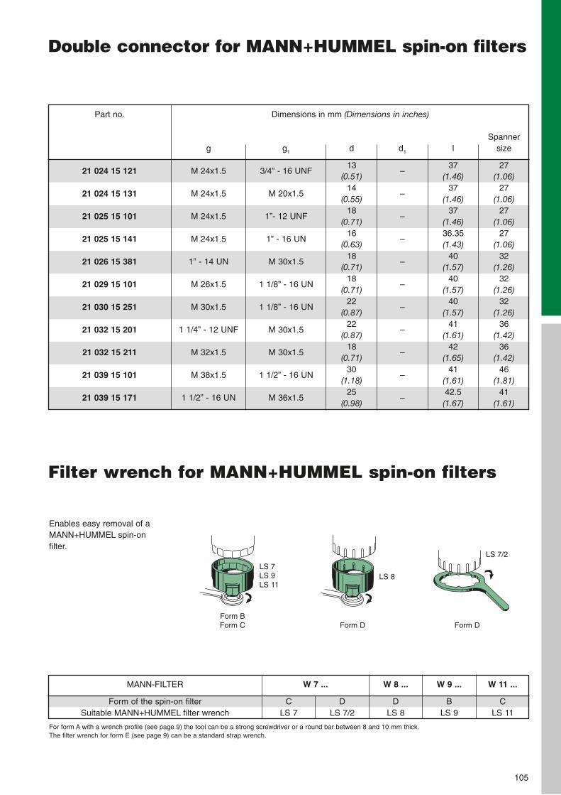
105
Double connector for MANN+HUMMEL spin-on filters
Enables easy removal of aMANN+HUMMEL spin-on filter.
For form A with a wrench profile (see page 9) the tool can be a strong screwdriver or a round bar between 8 and 10 mm thick. The filter wrench for form E (see page 9) can be a standard strap wrench.
MANN-FILTER
Form of the spin-on filterSuitable MANN+HUMMEL filter wrench
CLS 7
W 7 ...
DLS 7/2
W 8 ...
DLS 8
W 9 ...
BLS 9
W 11 ...
CLS 11
Form DForm DForm BForm C
LS 7LS 9LS 11
LS 8
LS 7/2
21 024 15 121
21 024 15 131
21 025 15 101
21 025 15 141
21 026 15 381
21 029 15 101
21 030 15 251
21 032 15 201
21 032 15 211
21 039 15 101
21 039 15 171
Part no. Dimensions in mm (Dimensions in inches)
g
M 24x1.5
M 24x1.5
M 24x1.5
M 24x1.5
1” - 14 UN
M 26x1.5
M 30x1.5
1 1/4” - 12 UNF
M 32x1.5
M 38x1.5
1 1/2” - 16 UN
g1
3/4” - 16 UNF
M 20x1.5
1”- 12 UNF
1” - 16 UN
M 30x1.5
1 1/8” - 16 UN
1 1/8” - 16 UN
M 30x1.5
M 30x1.5
1 1/2” - 16 UN
M 36x1.5
d
13(0.51)
14(0.55)
18(0.71)
16(0.63)
18(0.71)
18(0.71)
22(0.87)
22(0.87)
18(0.71)
30(1.18)
25(0.98)
d1
–
–
–
–
–
–
–
–
–
–
–
l
37(1.46)
37(1.46)
37(1.46)36.35(1.43)
40(1.57)
40(1.57)
40(1.57)
41(1.61)
42(1.65)
41(1.61)42.5(1.67)
Spannersize
27(1.06)
27(1.06)
27(1.06)
27(1.06)
32(1.26)
32(1.26)
32(1.26)
36(1.42)
36(1.42)
46(1.81)
41(1.61)
Filter wrench for MANN+HUMMEL spin-on filters
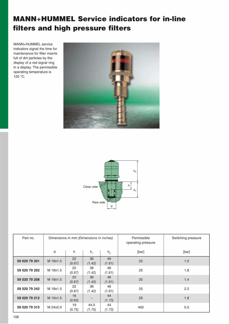
106
MANN+HUMMEL Service indicators for in-line filters and high pressure filters
MANN+HUMMEL serviceindicators signal the time formaintenance for filter insertsfull of dirt particles by thedisplay of a red signal ring in a display. The permissibleoperating temperature is 120 °C.
Clean sideh1
h
d
h2
Raw side
59 020 79 201
59 020 79 202
59 020 79 208
59 020 79 242
59 020 79 212
59 020 79 315
Part no. Dimensions in mm (Dimensions in inches)
d
M 18x1.5
M 18x1.5
M 18x1.5
M 18x1.5
M 10x1.5
M 24x2.0
h
22(0.87)
22(0.87)
22(0.87)
22(0.87)
16(0.63)
19(0.75)
h1
36(1.42)
36(1.42)
36(1.42)
36(1.42)
–
44.5(1.75)
h2
46(1.81)
46(1.81)
46(1.81)
46(1.81)
44(1.73)
44(1.73)
Switching pressure
[bar]
1.0
1.8
1.4
2.2
1.8
5.0
Permissible operating pressure
[bar]
25
25
25
25
25
400
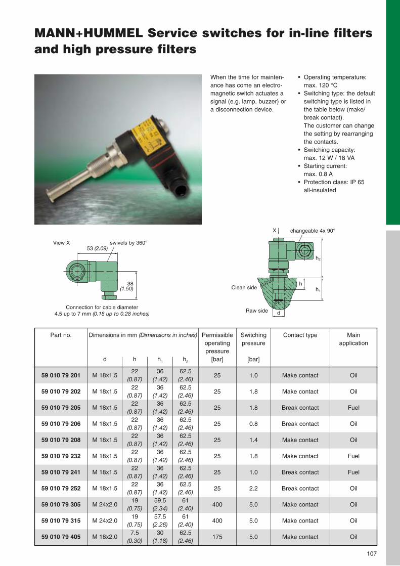
MANN+HUMMEL Service switches for in-line filtersand high pressure filters
59 010 79 201
59 010 79 202
59 010 79 205
59 010 79 206
59 010 79 208
59 010 79 232
59 010 79 241
59 010 79 252
59 010 79 305
59 010 79 315
59 010 79 405
Part no. Dimensions in mm (Dimensions in inches)
d
M 18x1.5
M 18x1.5
M 18x1.5
M 18x1.5
M 18x1.5
M 18x1.5
M 18x1.5
M 18x1.5
M 24x2.0
M 24x2.0
M 18x2.0
h
22(0.87)
22(0.87)
22(0.87)
22(0.87)
22(0.87)
22(0.87)
22(0.87)
22(0.87)
19(0.75)
19(0.75)7.5
(0.30)
h1
36(1.42)
36(1.42)
36(1.42)
36(1.42)
36(1.42)
36(1.42)
36(1.42)
36(1.42)59.5(2.34)57.5(2.26)
30(1.18)
h2
62.5(2.46)62.5(2.46)62.5(2.46)62.5(2.46)62.5(2.46)62.5(2.46)62.5(2.46)62.5(2.46)
61(2.40)
61(2.40)62.5(2.46)
107
Permissibleoperatingpressure
[bar]
25
25
25
25
25
25
25
25
400
400
175
Switchingpressure
[bar]
1.0
1.8
1.8
0.8
1.4
1.8
1.0
2.2
5.0
5.0
5.0
Contact type
Make contact
Make contact
Break contact
Break contact
Make contact
Make contact
Break contact
Break contact
Make contact
Make contact
Make contact
Main application
Oil
Oil
Fuel
Oil
Oil
Fuel
Fuel
Oil
Oil
Oil
Oil
When the time for mainten-ance has come an electro-magnetic switch actuates asignal (e.g. lamp, buzzer) ora disconnection device.
• Operating temperature:max. 120 °C
• Switching type: the defaultswitching type is listed inthe table below (make/break contact). The customer can changethe setting by rearrangingthe contacts.
• Switching capacity: max. 12 W / 18 VA
• Starting current: max. 0.8 A
• Protection class: IP 65 all-insulated
Clean side h1
h
d
h2
Raw side
X changeable 4x 90°
53 (2.09)
38 (1.50)
swivels by 360°
Connection for cable diameter 4.5 up to 7 mm (0.18 up to 0.28 inches)
View X
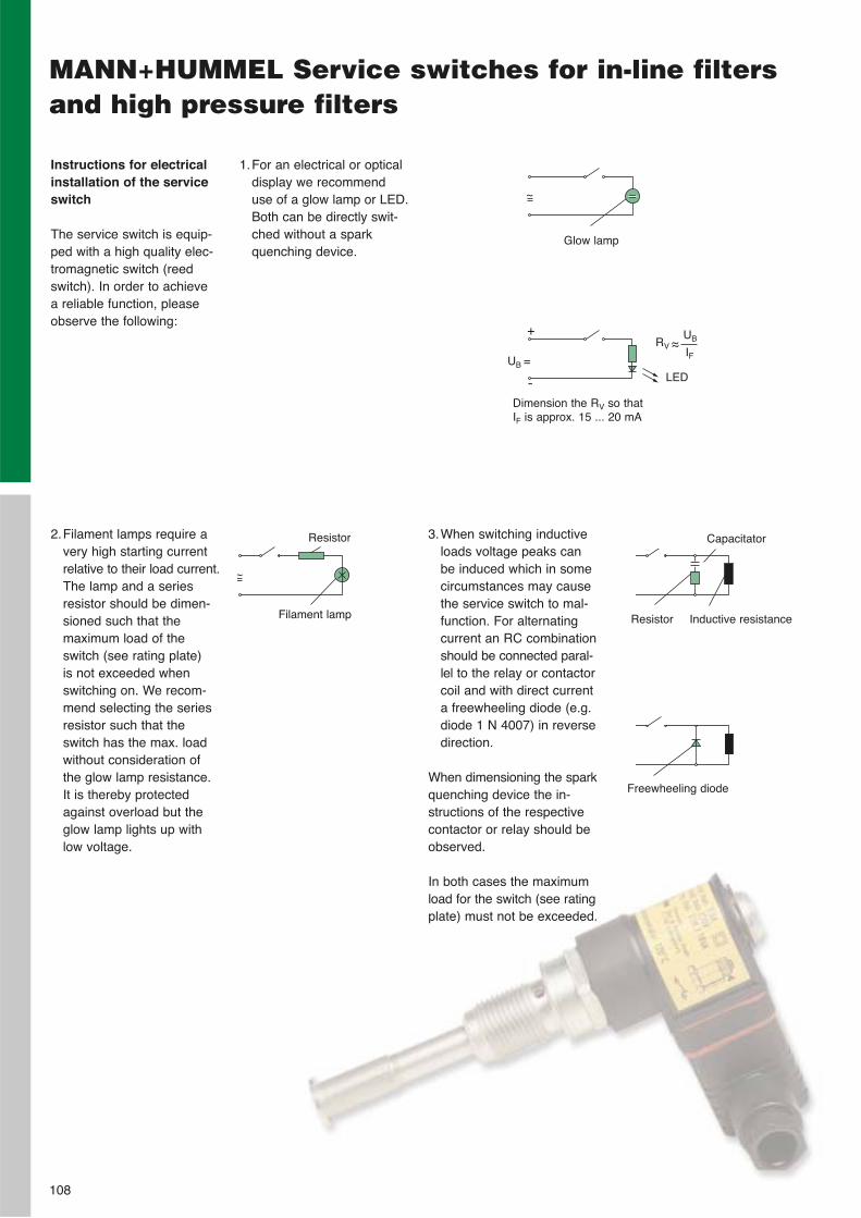
108
MANN+HUMMEL Service switches for in-line filtersand high pressure filters
Instructions for electricalinstallation of the serviceswitch
The service switch is equip-ped with a high quality elec-tromagnetic switch (reedswitch). In order to achieve a reliable function, pleaseobserve the following:
2.Filament lamps require avery high starting currentrelative to their load current.The lamp and a seriesresistor should be dimen-sioned such that the maximum load of theswitch (see rating plate) is not exceeded whenswitching on. We recom-mend selecting the seriesresistor such that theswitch has the max. loadwithout consideration ofthe glow lamp resistance.It is thereby protectedagainst overload but theglow lamp lights up withlow voltage.
3.When switching inductiveloads voltage peaks canbe induced which in somecircumstances may causethe service switch to mal-function. For alternatingcurrent an RC combinationshould be connected paral-lel to the relay or contactorcoil and with direct currenta freewheeling diode (e.g.diode 1 N 4007) in reversedirection.
When dimensioning the sparkquenching device the in-structions of the respectivecontactor or relay should beobserved.
In both cases the maximumload for the switch (see ratingplate) must not be exceeded.
~
+
-
~
Dimension the RV so thatIF is approx. 15 ... 20 mA
Resistor
Filament lamp
1.For an electrical or opticaldisplay we recommenduse of a glow lamp or LED.Both can be directly swit-ched without a sparkquenching device.
Resistor
Capacitator
Inductive resistance
Freewheeling diode
UB =
Glow lamp
RV ~~UB
IF
LED
Technical Annex
109
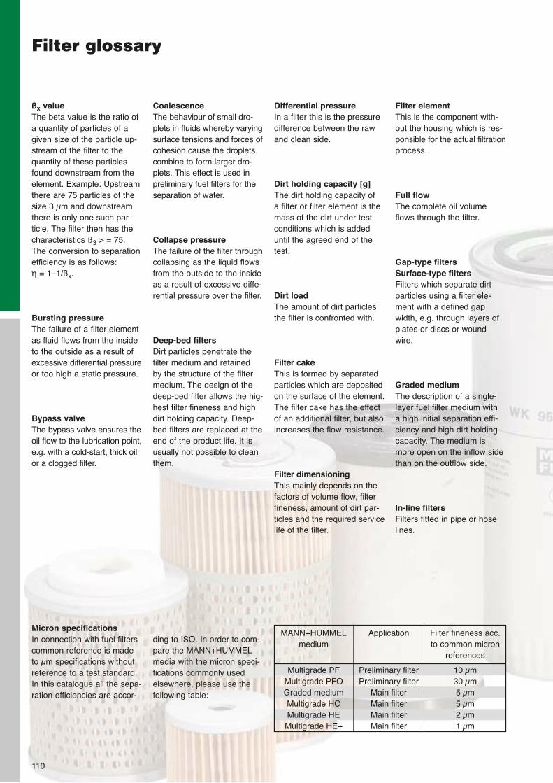
ßx valueThe beta value is the ratio ofa quantity of particles of agiven size of the particle up-stream of the filter to thequantity of these particlesfound downstream from theelement. Example: Upstreamthere are 75 particles of thesize 3 µm and downstreamthere is only one such par-ticle. The filter then has thecharacteristics ß3 > = 75.The conversion to separationefficiency is as follows: η = 1–1/ßx.
Bursting pressureThe failure of a filter elementas fluid flows from the insideto the outside as a result ofexcessive differential pressureor too high a static pressure.
Bypass valveThe bypass valve ensures theoil flow to the lubrication point,e.g. with a cold-start, thick oilor a clogged filter.
Filter glossary
110
Micron specificationsIn connection with fuel filterscommon reference is madeto µm specifications withoutreference to a test standard.In this catalogue all the sepa-ration efficiencies are accor-
Filter elementThis is the component with-out the housing which is res-ponsible for the actual filtrationprocess.
Full flowThe complete oil volumeflows through the filter.
Gap-type filters Surface-type filtersFilters which separate dirtparticles using a filter ele-ment with a defined gapwidth, e.g. through layers ofplates or discs or woundwire.
Graded mediumThe description of a single-layer fuel filter medium with a high initial separation effi-ciency and high dirt holdingcapacity. The medium ismore open on the inflow sidethan on the outflow side.
In-line filtersFilters fitted in pipe or hoselines.
ding to ISO. In order to com-pare the MANN+HUMMELmedia with the micron speci-fications commonly usedelsewhere, please use thefollowing table:
MANN+HUMMELmedium
Multigrade PFMultigrade PFOGraded mediumMultigrade HCMultigrade HE
Multigrade HE+
Application
Preliminary filterPreliminary filter
Main filterMain filterMain filterMain filter
Filter fineness acc. to common micron
references
10 µm30 µm5 µm5 µm2 µm1 µm
Coalescence The behaviour of small dro-plets in fluids whereby varyingsurface tensions and forces ofcohesion cause the dropletscombine to form larger dro-plets. This effect is used inpreliminary fuel filters for theseparation of water.
Collapse pressureThe failure of the filter throughcollapsing as the liquid flowsfrom the outside to the insideas a result of excessive diffe-rential pressure over the filter.
Deep-bed filtersDirt particles penetrate the filter medium and retained by the structure of the filtermedium. The design of thedeep-bed filter allows the hig-hest filter fineness and highdirt holding capacity. Deep-bed filters are replaced at theend of the product life. It isusually not possible to cleanthem.
Differential pressureIn a filter this is the pressuredifference between the rawand clean side.
Dirt holding capacity [g]The dirt holding capacity of a filter or filter element is themass of the dirt under testconditions which is addeduntil the agreed end of thetest.
Dirt loadThe amount of dirt particlesthe filter is confronted with.
Filter cakeThis is formed by separatedparticles which are depositedon the surface of the element.The filter cake has the effectof an additional filter, but alsoincreases the flow resistance.
Filter dimensioningThis mainly depends on thefactors of volume flow, filterfineness, amount of dirt par-ticles and the required servicelife of the filter.
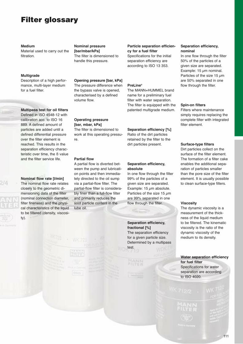
MediumMaterial used to carry out thefiltration.
MultigradeDescription of a high perfor-mance, multi-layer mediumfor a fuel filter.
Multipass test for oil filtersDefined in ISO 4548-12 withcalibration acc. to ISO 16889. A defined amount ofparticles are added until adefined differential pressureover the filter element is reached. This results in theseparation efficiency charac-teristic over time, the ß valueand the filter service life.
Nominal flow rate [l/min]The nominal flow rate relatesclosely to the geometric di-mensioning data of the filter(nominal connection diameter,filter fineness) and the physi-cal characteristics of the liquidto be filtered (density, viscosi-ty).
Nominal pressure[bar/mbar/kPa]The filter is dimensioned tohandle this pressure.
Opening pressure [bar, kPa]The pressure difference whenthe bypass valve is opened,characterised by a definedvolume flow.
Operating pressure [bar, mbar, kPa]The filter is dimensioned towork at this operating pressu-re.
Partial flowA partial flow is diverted bet-ween the pump and lubricati-on points and then immedia-tely directed to the oil sumpvia a partial-flow filter. Thepartial-flow filter is considera-bly finer than a full-flow filterand primarily reduces thesoot particle content in thelube oil.
Particle separation efficien-cy for a fuel filterSpecifications for the initialseparation efficiency areaccording to ISO 13 353.
PreLine®
The MANN+HUMMEL brandname for a preliminary fuelfilter with water separation.The filter is equipped with thepatented multigrade medium.
Separation efficiency [%]Ratio of the dirt particlesretained by the filter to thedirt particles present.
Separation efficiency,absoluteIn one flow through the filter99% of the particles of agiven size are separated.Example: 15 µm absolute.Particles of the size 15 µmare 99% separated in oneflow through the filter.
Separation efficiency, fractional [%]The separation efficiency for a given particle size.Determined by a multipasstest.
Separation efficiency,nominal In one flow through the filter50% of the particles of agiven size are separated.Example: 15 µm nominal.Particles of the size 15 µmare 50% separated in oneflow through the filter.
Spin-on filtersFilters where maintenancesimply requires replacing thecomplete filter with integratedfilter element.
Surface-type filtersDirt particles collect on thesurface of the filter element.The formation of a filter cakeenables the additional sepa-ration of particles smallerthan the pore size of the filterelement. It is usually possibleto clean surface-type filters.
ViscosityThe dynamic viscosity is ameasurement of the thick-ness of the liquid medium to be filtered. The kinematic viscosity is the ratio of thedynamic viscosity of themedium to its density.
Water separation efficiencyfor fuel filterSpecifications for water separation are according to ISO 4020.
111
Filter glossary
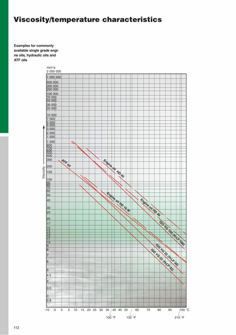
112
Viscosity/temperature characteristics
Examples for commonlyavailable single grade engi-ne oils, hydraulic oils andATF oils
Vis
cosi
ty
100 °F
-10 -5 0 5 10 15 20 25 30 35 40 45 50 60 70 80 90 100 °C
130 °F 210 °F
mm2/s2 000 000
1 000 000
500 000300 000200 000100 00070 00050 00030 00020 000
10 0007 0005 0004 0003 0002 0001 500
1 000800700600500400300
200
150
1009080706050
40
3025
20
1715141312111098
7
6
5
4.5
4
3.5
32.8
Engine oil HD 40
Engine oil HD 30
ISO VG 100 (H-LP100)
Engine oil HD 10 W
ATF oil
ISO VG 32 (H-LP32)
ISO VG 22 (H-LP22)
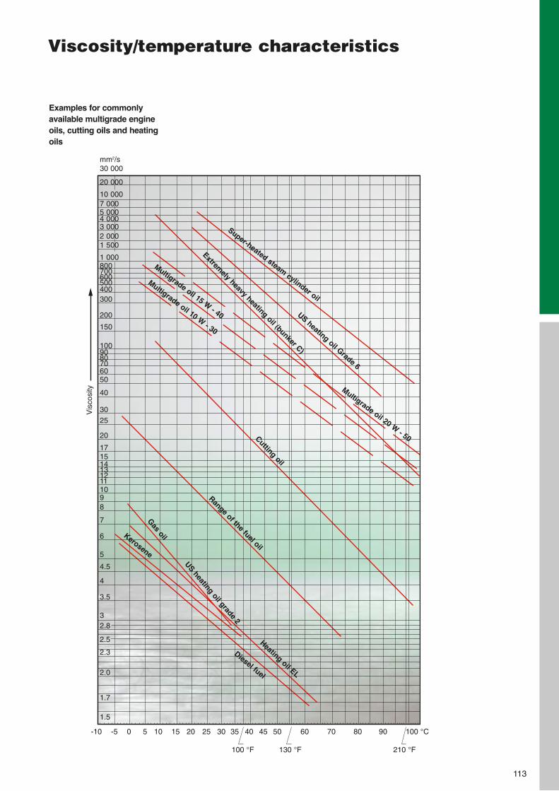
113
Viscosity/temperature characteristics
Examples for commonlyavailable multigrade engineoils, cutting oils and heatingoils
Vis
cosi
ty
100 °F
-10 -5 0 5 10 15 20 25 30 35 40 45 50 60 70 80 90 100 °C
130 °F 210 °F
Super-heated steam cylinder oil
US heating oil Grade 6
Extremely heavy heating oil (bunker C)
Multigrade oil 20 W - 50
Multigrade oil 15 W - 40
Multigrade oil 10 W - 30
Cutting oil
Range of the fuel oil
Heating oil EL
Gas oil
US heating oil grade 2
Kerosene
Diesel fuel
mm2/s30 000
20 000
10 0007 0005 0004 0003 0002 0001 500
1 000800700600500400300
200
150
1009080706050
40
3025
20
1715141312111098
7
6
5
4.5
4
3.5
32.8
2.5
2.3
2.0
1.7
1.5
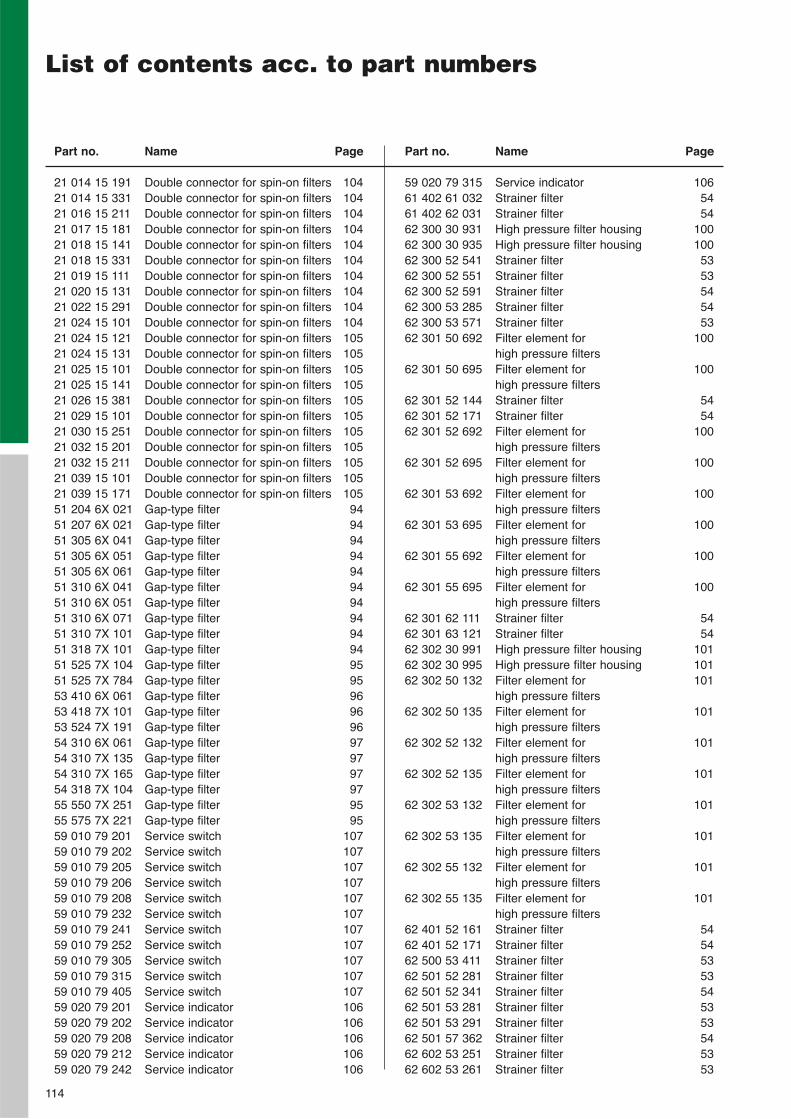
114
List of contents acc. to part numbers
Part no. Name Page
21 014 15 191 Double connector for spin-on filters 10421 014 15 331 Double connector for spin-on filters 10421 016 15 211 Double connector for spin-on filters 10421 017 15 181 Double connector for spin-on filters 10421 018 15 141 Double connector for spin-on filters 10421 018 15 331 Double connector for spin-on filters 10421 019 15 111 Double connector for spin-on filters 10421 020 15 131 Double connector for spin-on filters 10421 022 15 291 Double connector for spin-on filters 10421 024 15 101 Double connector for spin-on filters 10421 024 15 121 Double connector for spin-on filters 10521 024 15 131 Double connector for spin-on filters 10521 025 15 101 Double connector for spin-on filters 10521 025 15 141 Double connector for spin-on filters 10521 026 15 381 Double connector for spin-on filters 10521 029 15 101 Double connector for spin-on filters 10521 030 15 251 Double connector for spin-on filters 10521 032 15 201 Double connector for spin-on filters 10521 032 15 211 Double connector for spin-on filters 10521 039 15 101 Double connector for spin-on filters 10521 039 15 171 Double connector for spin-on filters 10551 204 6X 021 Gap-type filter 9451 207 6X 021 Gap-type filter 9451 305 6X 041 Gap-type filter 9451 305 6X 051 Gap-type filter 9451 305 6X 061 Gap-type filter 9451 310 6X 041 Gap-type filter 9451 310 6X 051 Gap-type filter 9451 310 6X 071 Gap-type filter 9451 310 7X 101 Gap-type filter 9451 318 7X 101 Gap-type filter 9451 525 7X 10⁴ Gap-type filter 9551 525 7X 784 Gap-type filter 9553 410 6X 061 Gap-type filter 9653 418 7X 101 Gap-type filter 9653 524 7X 191 Gap-type filter 9654 310 6X 061 Gap-type filter 9754 310 7X 135 Gap-type filter 9754 310 7X 165 Gap-type filter 9754 318 7X 10⁴ Gap-type filter 9755 550 7X 251 Gap-type filter 9555 575 7X 221 Gap-type filter 9559 010 79 201 Service switch 10759 010 79 202 Service switch 10759 010 79 205 Service switch 10759 010 79 206 Service switch 10759 010 79 208 Service switch 10759 010 79 232 Service switch 10759 010 79 241 Service switch 10759 010 79 252 Service switch 10759 010 79 305 Service switch 10759 010 79 315 Service switch 10759 010 79 405 Service switch 10759 020 79 201 Service indicator 10659 020 79 202 Service indicator 10659 020 79 208 Service indicator 10659 020 79 212 Service indicator 10659 020 79 242 Service indicator 106
Part no. Name Page
59 020 79 315 Service indicator 10661 402 61 032 Strainer filter 5461 402 62 031 Strainer filter 5462 300 30 931 High pressure filter housing 10062 300 30 935 High pressure filter housing 10062 300 52 541 Strainer filter 5362 300 52 551 Strainer filter 5362 300 52 591 Strainer filter 5462 300 53 285 Strainer filter 5462 300 53 571 Strainer filter 5362 301 50 692 Filter element for 100
high pressure filters 62 301 50 695 Filter element for 100
high pressure filters62 301 52 144 Strainer filter 5462 301 52 171 Strainer filter 5462 301 52 692 Filter element for 100
high pressure filters62 301 52 695 Filter element for 100
high pressure filters62 301 53 692 Filter element for 100
high pressure filters62 301 53 695 Filter element for 100
high pressure filters62 301 55 692 Filter element for 100
high pressure filters62 301 55 695 Filter element for 100
high pressure filters62 301 62 111 Strainer filter 5462 301 63 121 Strainer filter 5462 302 30 991 High pressure filter housing 10162 302 30 995 High pressure filter housing 10162 302 50 132 Filter element for 101
high pressure filters62 302 50 135 Filter element for 101
high pressure filters62 302 52 132 Filter element for 101
high pressure filters62 302 52 135 Filter element for 101
high pressure filters62 302 53 132 Filter element for 101
high pressure filters62 302 53 135 Filter element for 101
high pressure filters62 302 55 132 Filter element for 101
high pressure filters62 302 55 135 Filter element for 101
high pressure filters62 401 52 161 Strainer filter 5462 401 52 171 Strainer filter 5462 500 53 411 Strainer filter 5362 501 52 281 Strainer filter 5362 501 52 341 Strainer filter 5462 501 53 281 Strainer filter 5362 501 53 291 Strainer filter 5362 501 57 362 Strainer filter 5462 602 53 251 Strainer filter 5362 602 53 261 Strainer filter 53
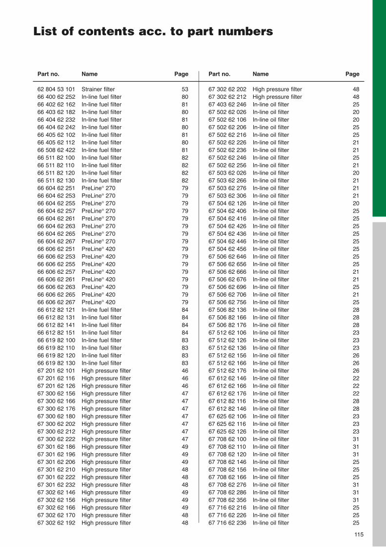
115
List of contents acc. to part numbers
Part no. Name Page
62 804 53 101 Strainer filter 5366 400 62 252 In-line fuel filter 8066 402 62 162 In-line fuel filter 8166 403 62 182 In-line fuel filter 8066 404 62 232 In-line fuel filter 8166 404 62 242 In-line fuel filter 8066 405 62 102 In-line fuel filter 8166 405 62 112 In-line fuel filter 8066 508 62 422 In-line fuel filter 8166 511 82 100 In-line fuel filter 8266 511 82 110 In-line fuel filter 8266 511 82 120 In-line fuel filter 8266 511 82 130 In-line fuel filter 8266 604 62 251 PreLine® 270 7966 604 62 253 PreLine® 270 7966 604 62 255 PreLine® 270 7966 604 62 257 PreLine® 270 7966 604 62 261 PreLine® 270 7966 604 62 263 PreLine® 270 7966 604 62 265 PreLine® 270 7966 604 62 267 PreLine® 270 7966 606 62 251 PreLine® 420 7966 606 62 253 PreLine® 420 7966 606 62 255 PreLine® 420 7966 606 62 257 PreLine® 420 7966 606 62 261 PreLine® 420 7966 606 62 263 PreLine® 420 7966 606 62 265 PreLine® 420 7966 606 62 267 PreLine® 420 7966 612 82 121 In-line fuel filter 8466 612 82 131 In-line fuel filter 8466 612 82 141 In-line fuel filter 8466 612 82 151 In-line fuel filter 8466 619 82 100 In-line fuel filter 8366 619 82 110 In-line fuel filter 8366 619 82 120 In-line fuel filter 8366 619 82 130 In-line fuel filter 8367 201 62 101 High pressure filter 4667 201 62 116 High pressure filter 4667 201 62 126 High pressure filter 4667 300 62 156 High pressure filter 4767 300 62 166 High pressure filter 4767 300 62 176 High pressure filter 4767 300 62 180 High pressure filter 4767 300 62 202 High pressure filter 4767 300 62 212 High pressure filter 4767 300 62 222 High pressure filter 4767 301 62 186 High pressure filter 4967 301 62 196 High pressure filter 4967 301 62 206 High pressure filter 4967 301 62 210 High pressure filter 4867 301 62 222 High pressure filter 4867 301 62 232 High pressure filter 4867 302 62 146 High pressure filter 4967 302 62 156 High pressure filter 4967 302 62 166 High pressure filter 4967 302 62 170 High pressure filter 4867 302 62 192 High pressure filter 48
Part no. Name Page
67 302 62 202 High pressure filter 4867 302 62 212 High pressure filter 4867 403 62 246 In-line oil filter 2567 502 62 026 In-line oil filter 2067 502 62 106 In-line oil filter 2067 502 62 206 In-line oil filter 2567 502 62 216 In-line oil filter 2567 502 62 226 In-line oil filter 2167 502 62 236 In-line oil filter 2167 502 62 246 In-line oil filter 2567 502 62 256 In-line oil filter 2167 503 62 026 In-line oil filter 2067 503 62 266 In-line oil filter 2167 503 62 276 In-line oil filter 2167 503 62 306 In-line oil filter 2167 504 62 126 In-line oil filter 2067 504 62 406 In-line oil filter 2567 504 62 416 In-line oil filter 2567 504 62 426 In-line oil filter 2567 504 62 436 In-line oil filter 2567 504 62 446 In-line oil filter 2567 504 62 456 In-line oil filter 2567 506 62 646 In-line oil filter 2567 506 62 656 In-line oil filter 2567 506 62 666 In-line oil filter 2167 506 62 676 In-line oil filter 2167 506 62 696 In-line oil filter 2567 506 62 706 In-line oil filter 2167 506 62 756 In-line oil filter 2567 506 82 136 In-line oil filter 2867 506 82 166 In-line oil filter 2867 506 82 176 In-line oil filter 2867 512 62 106 In-line oil filter 2367 512 62 126 In-line oil filter 2367 512 62 136 In-line oil filter 2367 512 62 156 In-line oil filter 2667 512 62 166 In-line oil filter 2667 512 62 176 In-line oil filter 2667 612 62 146 In-line oil filter 2267 612 62 166 In-line oil filter 2267 612 62 176 In-line oil filter 2267 612 82 116 In-line oil filter 2867 612 82 146 In-line oil filter 2867 625 62 106 In-line oil filter 2367 625 62 116 In-line oil filter 2367 625 62 126 In-line oil filter 2367 708 62 100 In-line oil filter 3167 708 62 110 In-line oil filter 3167 708 62 120 In-line oil filter 3167 708 62 146 In-line oil filter 2567 708 62 156 In-line oil filter 2567 708 62 166 In-line oil filter 2567 708 62 276 In-line oil filter 3167 708 62 286 In-line oil filter 3167 708 62 356 In-line oil filter 3167 716 62 216 In-line oil filter 2567 716 62 226 In-line oil filter 2567 716 62 236 In-line oil filter 25
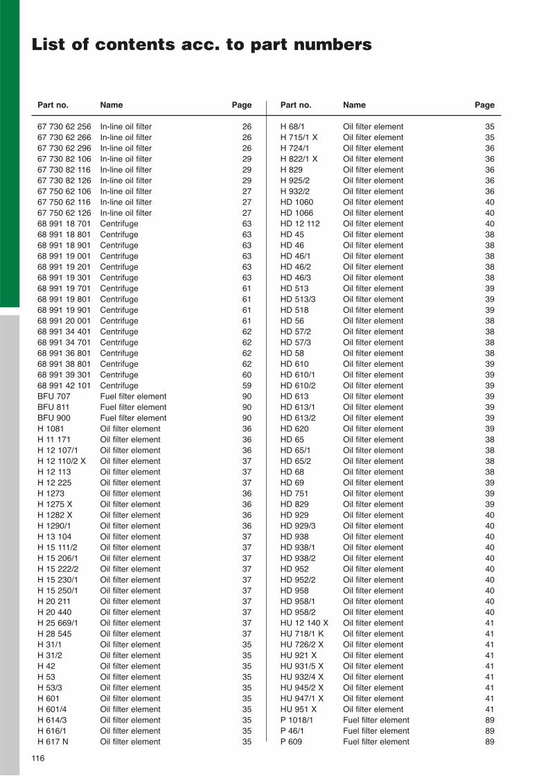
116
List of contents acc. to part numbers
Part no. Name Page
67 730 62 256 In-line oil filter 2667 730 62 266 In-line oil filter 2667 730 62 296 In-line oil filter 2667 730 82 106 In-line oil filter 2967 730 82 116 In-line oil filter 2967 730 82 126 In-line oil filter 2967 750 62 106 In-line oil filter 2767 750 62 116 In-line oil filter 2767 750 62 126 In-line oil filter 2768 991 18 701 Centrifuge 6368 991 18 801 Centrifuge 6368 991 18 901 Centrifuge 6368 991 19 001 Centrifuge 6368 991 19 201 Centrifuge 6368 991 19 301 Centrifuge 6368 991 19 701 Centrifuge 6168 991 19 801 Centrifuge 6168 991 19 901 Centrifuge 6168 991 20 001 Centrifuge 6168 991 34 401 Centrifuge 6268 991 34 701 Centrifuge 6268 991 36 801 Centrifuge 6268 991 38 801 Centrifuge 6268 991 39 301 Centrifuge 6068 991 42 101 Centrifuge 59BFU 707 Fuel filter element 90BFU 811 Fuel filter element 90BFU 900 Fuel filter element 90H 1081 Oil filter element 36H 11 171 Oil filter element 36H 12 107/1 Oil filter element 36H 12 110/2 X Oil filter element 37H 12 113 Oil filter element 37H 12 225 Oil filter element 37H 1273 Oil filter element 36H 1275 X Oil filter element 36H 1282 X Oil filter element 36H 1290/1 Oil filter element 36H 13 104 Oil filter element 37H 15 111/2 Oil filter element 37H 15 206/1 Oil filter element 37H 15 222/2 Oil filter element 37H 15 230/1 Oil filter element 37H 15 250/1 Oil filter element 37H 20 211 Oil filter element 37H 20 440 Oil filter element 37H 25 669/1 Oil filter element 37H 28 545 Oil filter element 37H 31/1 Oil filter element 35H 31/2 Oil filter element 35H 42 Oil filter element 35H 53 Oil filter element 35H 53/3 Oil filter element 35H 601 Oil filter element 35H 601/4 Oil filter element 35H 614/3 Oil filter element 35H 616/1 Oil filter element 35H 617 N Oil filter element 35
Part no. Name Page
H 68/1 Oil filter element 35H 715/1 X Oil filter element 35H 724/1 Oil filter element 36H 822/1 X Oil filter element 36H 829 Oil filter element 36H 925/2 Oil filter element 36H 932/2 Oil filter element 36HD 1060 Oil filter element 40HD 1066 Oil filter element 40HD 12 112 Oil filter element 40HD 45 Oil filter element 38HD 46 Oil filter element 38HD 46/1 Oil filter element 38HD 46/2 Oil filter element 38HD 46/3 Oil filter element 38HD 513 Oil filter element 39HD 513/3 Oil filter element 39HD 518 Oil filter element 39HD 56 Oil filter element 38HD 57/2 Oil filter element 38HD 57/3 Oil filter element 38HD 58 Oil filter element 38HD 610 Oil filter element 39HD 610/1 Oil filter element 39HD 610/2 Oil filter element 39HD 613 Oil filter element 39HD 613/1 Oil filter element 39HD 613/2 Oil filter element 39HD 620 Oil filter element 39HD 65 Oil filter element 38HD 65/1 Oil filter element 38HD 65/2 Oil filter element 38HD 68 Oil filter element 38HD 69 Oil filter element 39HD 751 Oil filter element 39HD 829 Oil filter element 39HD 929 Oil filter element 40HD 929/3 Oil filter element 40HD 938 Oil filter element 40HD 938/1 Oil filter element 40HD 938/2 Oil filter element 40HD 952 Oil filter element 40HD 952/2 Oil filter element 40HD 958 Oil filter element 40HD 958/1 Oil filter element 40HD 958/2 Oil filter element 40HU 12 140 X Oil filter element 41HU 718/1 K Oil filter element 41HU 726/2 X Oil filter element 41HU 921 X Oil filter element 41HU 931/5 X Oil filter element 41HU 932/4 X Oil filter element 41HU 945/2 X Oil filter element 41HU 947/1 X Oil filter element 41HU 951 X Oil filter element 41P 1018/1 Fuel filter element 89P 46/1 Fuel filter element 89P 609 Fuel filter element 89
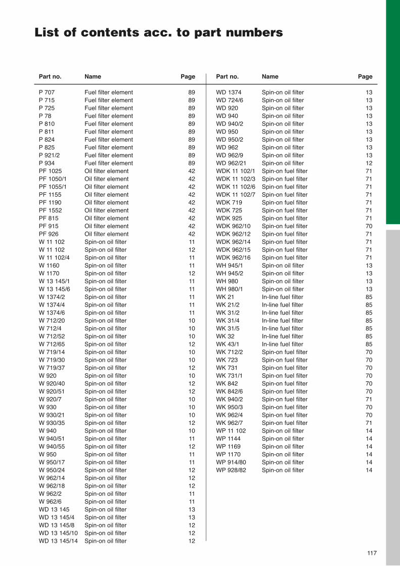
117
List of contents acc. to part numbers
Part no. Name Page
P 707 Fuel filter element 89P 715 Fuel filter element 89P 725 Fuel filter element 89P 78 Fuel filter element 89P 810 Fuel filter element 89P 811 Fuel filter element 89P 824 Fuel filter element 89P 825 Fuel filter element 89P 921/2 Fuel filter element 89P 934 Fuel filter element 89PF 1025 Oil filter element 42PF 1050/1 Oil filter element 42PF 1055/1 Oil filter element 42PF 1155 Oil filter element 42PF 1190 Oil filter element 42PF 1552 Oil filter element 42PF 815 Oil filter element 42PF 915 Oil filter element 42PF 926 Oil filter element 42W 11 102 Spin-on oil filter 11W 11 102 Spin-on oil filter 12W 11 102/4 Spin-on oil filter 11W 1160 Spin-on oil filter 11W 1170 Spin-on oil filter 12W 13 145/1 Spin-on oil filter 11W 13 145/6 Spin-on oil filter 11W 1374/2 Spin-on oil filter 11W 1374/4 Spin-on oil filter 11W 1374/6 Spin-on oil filter 11W 712/20 Spin-on oil filter 10W 712/4 Spin-on oil filter 10W 712/52 Spin-on oil filter 10W 712/65 Spin-on oil filter 12W 719/14 Spin-on oil filter 10W 719/30 Spin-on oil filter 10W 719/37 Spin-on oil filter 12W 920 Spin-on oil filter 10W 920/40 Spin-on oil filter 12W 920/51 Spin-on oil filter 12W 920/7 Spin-on oil filter 10W 930 Spin-on oil filter 10W 930/21 Spin-on oil filter 10W 930/35 Spin-on oil filter 12W 940 Spin-on oil filter 10W 940/51 Spin-on oil filter 11W 940/55 Spin-on oil filter 12W 950 Spin-on oil filter 11W 950/17 Spin-on oil filter 11W 950/24 Spin-on oil filter 12W 962/14 Spin-on oil filter 12W 962/18 Spin-on oil filter 12W 962/2 Spin-on oil filter 11W 962/6 Spin-on oil filter 11WD 13 145 Spin-on oil filter 13WD 13 145/4 Spin-on oil filter 13WD 13 145/8 Spin-on oil filter 12WD 13 145/10 Spin-on oil filter 12WD 13 145/14 Spin-on oil filter 12
Part no. Name Page
WD 1374 Spin-on oil filter 13WD 724/6 Spin-on oil filter 13WD 920 Spin-on oil filter 13WD 940 Spin-on oil filter 13WD 940/2 Spin-on oil filter 13WD 950 Spin-on oil filter 13WD 950/2 Spin-on oil filter 13WD 962 Spin-on oil filter 13WD 962/9 Spin-on oil filter 13WD 962/21 Spin-on oil filter 12WDK 11 102/1 Spin-on fuel filter 71WDK 11 102/3 Spin-on fuel filter 71WDK 11 102/6 Spin-on fuel filter 71WDK 11 102/7 Spin-on fuel filter 71WDK 719 Spin-on fuel filter 71WDK 725 Spin-on fuel filter 71WDK 925 Spin-on fuel filter 71WDK 962/10 Spin-on fuel filter 70WDK 962/12 Spin-on fuel filter 71WDK 962/14 Spin-on fuel filter 71WDK 962/15 Spin-on fuel filter 71WDK 962/16 Spin-on fuel filter 71WH 945/1 Spin-on oil filter 13WH 945/2 Spin-on oil filter 13WH 980 Spin-on oil filter 13WH 980/1 Spin-on oil filter 13WK 21 In-line fuel filter 85WK 21/2 In-line fuel filter 85WK 31/2 In-line fuel filter 85WK 31/4 In-line fuel filter 85WK 31/5 In-line fuel filter 85WK 32 In-line fuel filter 85WK 43/1 In-line fuel filter 85WK 712/2 Spin-on fuel filter 70WK 723 Spin-on fuel filter 70WK 731 Spin-on fuel filter 70WK 731/1 Spin-on fuel filter 70WK 842 Spin-on fuel filter 70WK 842/6 Spin-on fuel filter 70WK 940/2 Spin-on fuel filter 71WK 950/3 Spin-on fuel filter 70WK 962/4 Spin-on fuel filter 70WK 962/7 Spin-on fuel filter 71WP 11 102 Spin-on oil filter 14WP 1144 Spin-on oil filter 14WP 1169 Spin-on oil filter 14WP 1170 Spin-on oil filter 14WP 914/80 Spin-on oil filter 14WP 928/82 Spin-on oil filter 14
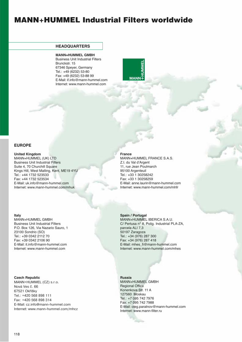
HEADQUARTERS
MANN+HUMMEL GMBHBusiness Unit Industrial FiltersBrunckstr. 1567346 Speyer, Germany Tel.: +49 (6232) 53-80Fax: +49 (6232) 53-88 99E-Mail: [email protected]: www.mann-hummel.com
MANN+HUMMEL Industrial Filters worldwide
118
EUROPE
United KingdomMANN+HUMMEL (UK) LTDBusiness Unit Industrial FiltersSuite 4, 70 Churchill SquareKings Hill, West Malling, Kent, ME19 4YUTel.: +44 1732 523533Fax: +44 1732 523534E-Mail: [email protected]: www.mann-hummel.com/mhuk
FranceMANN+HUMMEL FRANCE S.A.S.Z.I. du Val d’Argent11, rue Jean Poulmarch95100 ArgenteuilTel.: +33 1 30258242Fax: +33 1 30258259E-Mail: [email protected]: www.mann-hummel.com/mhfr
ItalyMANN+HUMMEL GMBHBusiness Unit Industrial FiltersP.O. Box 126, Via Nazario Sauro, 123100 Sondrio (SO)Tel.: +39 0342 2112 70Fax: +39 0342 2106 90E-Mail: [email protected]: www.mann-hummel.com
Spain / PortugalMANN+HUMMEL IBERICA S.A.U.C/ Pertusa n° 8, Polig. Industrial PLA-ZA,parcela ALI 7,350197 ZaragozaTel.: +34 (976) 287 300Fax: +34 (976) 287 418E-Mail: [email protected]: www.mann-hummel.com/mhes
Czech RepublicMANN+HUMMEL (CZ) s.r.o.Nová Ves č. 6667521 OkříškyTel.: +420 568 898 111Fax: +420 568 898 314E-Mail: [email protected]: www.mann-hummel.com/mhcz
RussiaMANN+HUMMEL GMBHRegional OfficeKonenkova Str. 11 A127560 MoskauTel.: +7 095 742 7976Fax: +7 095 742 7988E-Mail: [email protected] Internet: www.mann-filter.ru
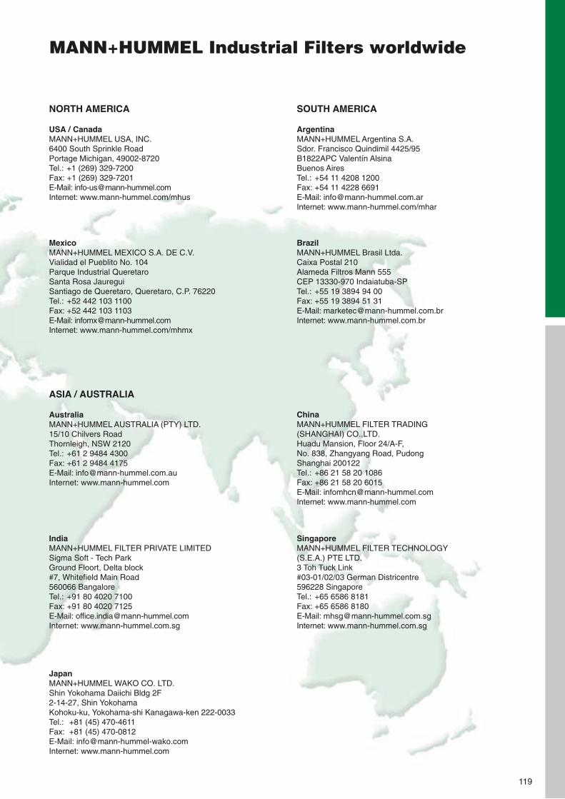
MANN+HUMMEL Industrial Filters worldwide
119
NORTH AMERICA
USA / CanadaMANN+HUMMEL USA, INC.6400 South Sprinkle RoadPortage Michigan, 49002-8720Tel.: +1 (269) 329-7200Fax: +1 (269) 329-7201E-Mail: [email protected]: www.mann-hummel.com/mhus
SOUTH AMERICA
ArgentinaMANN+HUMMEL Argentina S.A.Sdor. Francisco Quindimil 4425/95B1822APC Valentín AlsinaBuenos AiresTel.: +54 11 4208 1200Fax: +54 11 4228 6691E-Mail: [email protected]: www.mann-hummel.com/mhar
MexicoMANN+HUMMEL MEXICO S.A. DE C.V.Vialidad el Pueblito No. 104Parque Industrial QueretaroSanta Rosa JaureguiSantiago de Queretaro, Queretaro, C.P. 76220Tel.: +52 442 103 1100Fax: +52 442 103 1103E-Mail: [email protected]: www.mann-hummel.com/mhmx
BrazilMANN+HUMMEL Brasil Ltda.Caixa Postal 210Alameda Filtros Mann 555CEP 13330-970 Indaiatuba-SPTel.: +55 19 3894 94 00Fax: +55 19 3894 51 31E-Mail: [email protected]: www.mann-hummel.com.br
ASIA / AUSTRALIA
AustraliaMANN+HUMMEL AUSTRALIA (PTY) LTD.15/10 Chilvers RoadThornleigh, NSW 2120Tel.: +61 2 9484 4300Fax: +61 2 9484 4175E-Mail: [email protected]: www.mann-hummel.com
ChinaMANN+HUMMEL FILTER TRADING (SHANGHAI) CO.,LTD.Huadu Mansion, Floor 24/A-F, No. 838, Zhangyang Road, PudongShanghai 200122Tel.: +86 21 58 20 1086Fax: +86 21 58 20 6015E-Mail: [email protected]: www.mann-hummel.com
IndiaMANN+HUMMEL FILTER PRIVATE LIMITEDSigma Soft - Tech ParkGround Floort, Delta block#7, Whitefield Main Road560066 BangaloreTel.: +91 80 4020 7100Fax: +91 80 4020 7125E-Mail: [email protected]: www.mann-hummel.com.sg
SingaporeMANN+HUMMEL FILTER TECHNOLOGY(S.E.A.) PTE LTD.3 Toh Tuck Link#03-01/02/03 German Districentre596228 SingaporeTel.: +65 6586 8181Fax: +65 6586 8180E-Mail: [email protected]: www.mann-hummel.com.sg
JapanMANN+HUMMEL WAKO CO. LTD.Shin Yokohama Daiichi Bldg 2F2-14-27, Shin YokohamaKohoku-ku, Yokohama-shi Kanagawa-ken 222-0033Tel.: +81 (45) 470-4611Fax: +81 (45) 470-0812E-Mail: [email protected]: www.mann-hummel.com

Notes
120

Notes
121

Notes
122

Notes
123
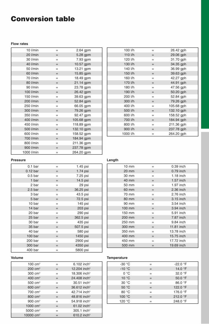
Conversion table
Temperature
-30 °C = -22.0 °F-10 °C = 14.0 °F
0 °C = 32.0 °F10 °C = 50.0 °F30 °C = 86.0 °F50 °C = 122.0 °F80 °C = 176.0 °F
100 °C = 212.0 °F120 °C = 248.0 °F
100 l/h = 26.42 gph110 l/h = 29.06 gph120 l/h = 31.70 gph130 l/h = 34.35 gph140 l/h = 36.99 gph150 l/h = 39.63 gph160 l/h = 42.27 gph170 l/h = 44.91 gph180 l/h = 47.56 gph190 l/h = 50.20 gph200 l/h = 52.84 gph300 l/h = 79.26 gph400 l/h = 105.68 gph500 l/h = 132.10 gph600 l/h = 158.52 gph700 l/h = 184.94 gph800 l/h = 211.36 gph900 l/h = 237.78 gph
1000 l/h = 264.20 gph
Flow rates
10 l/min = 2.64 gpm20 l/min = 5.28 gpm30 l/min = 7.93 gpm40 l/min = 10.57 gpm50 l/min = 13.21 gpm60 l/min = 15.85 gpm70 l/min = 18.49 gpm80 l/min = 21.14 gpm90 l/min = 23.78 gpm
100 l/min = 26.42 gpm150 l/min = 39.63 gpm200 l/min = 52.84 gpm250 l/min = 66.05 gpm300 l/min = 79.26 gpm350 l/min = 92.47 gpm400 l/min = 105.68 gpm450 l/min = 118.89 gpm500 l/min = 132.10 gpm600 l/min = 158.52 gpm700 l/min = 184.94 gpm800 l/min = 211.36 gpm900 l/min = 237.78 gpm
1000 l/min = 264.20 gpm
Length
10 mm = 0.39 inch20 mm = 0.79 inch30 mm = 1.18 inch40 mm = 1.57 inch50 mm = 1.97 inch60 mm = 2.36 inch70 mm = 2.76 inch80 mm = 3.15 inch90 mm = 3.54 inch
100 mm = 3.94 inch150 mm = 5.91 inch200 mm = 7.87 inch250 mm = 9.84 inch300 mm = 11.81 inch350 mm = 13.78 inch400 mm = 15.75 inch450 mm = 17.72 inch500 mm = 19.69 inch
Volume
100 cm3 = 6.102 inch3
200 cm3 = 12.204 inch3
300 cm3 = 18.306 inch3
400 cm3 = 24.408 inch3
500 cm3 = 30.51 inch3
600 cm3 = 36.612 inch3
700 cm3 = 42.714 inch3
800 cm3 = 48.816 inch3
900 cm3 = 54.918 inch3
1000 cm3 = 61.02 inch3
5000 cm3 = 305.1 inch3
10000 cm3 = 610.2 inch3
Pressure
0.1 bar = 1.45 psi0.12 bar = 1.74 psi0.5 bar = 7.25 psi
1 bar = 14.5 psi2 bar = 29 psi
2.5 bar = 36.25 psi3 bar = 43.5 psi5 bar = 72.5 psi
10 bar = 145 psi14 bar = 203 psi20 bar = 290 psi25 bar = 362.5 psi30 bar = 435 psi35 bar = 507.5 psi40 bar = 580 psi
100 bar = 1450 psi200 bar = 2900 psi300 bar = 4350 psi400 bar = 5800 psi
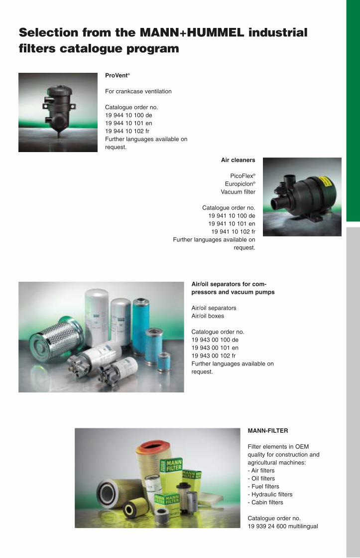
Selection from the MANN+HUMMEL industrial filters catalogue program
Air cleaners
PicoFlex®
Europiclon®
Vacuum filter
Catalogue order no.19 941 10 100 de19 941 10 101 en19 941 10 102 fr
Further languages available on request.
ProVent®
For crankcase ventilation
Catalogue order no.19 944 10 100 de19 944 10 101 en19 944 10 102 frFurther languages available onrequest.
MANN-FILTER
Filter elements in OEM quality for construction andagricultural machines:- Air filters- Oil filters- Fuel filters- Hydraulic filters- Cabin filters
Catalogue order no.19 939 24 600 multilingual
Air/oil separators for com-pressors and vacuum pumps
Air/oil separatorsAir/oil boxes
Catalogue order no.19 943 00 100 de19 943 00 101 en19 943 00 102 frFurther languages available onrequest.
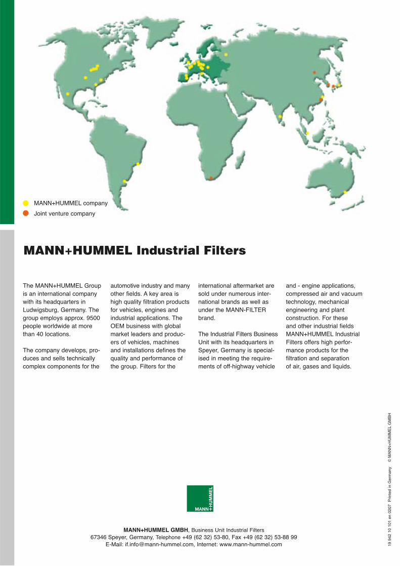
MANN+HUMMEL GMBH, Business Unit Industrial Filters67346 Speyer, Germany, Telephone +49 (62 32) 53-80, Fax +49 (62 32) 53-88 99
E-Mail: [email protected], Internet: www.mann-hummel.com 19 9
42 1
0 10
1 en
020
7 P
rinte
d in
Ger
man
y
©M
AN
N+
HU
MM
EL
GM
BH
MANN+HUMMEL Industrial Filters
MANN+HUMMEL company
Joint venture company
automotive industry and manyother fields. A key area ishigh quality filtration productsfor vehicles, engines andindustrial applications. TheOEM business with globalmarket leaders and produc-ers of vehicles, machinesand installations defines thequality and performance ofthe group. Filters for the
The MANN+HUMMEL Groupis an international companywith its headquarters inLudwigsburg, Germany. Thegroup employs approx. 9500people worldwide at morethan 40 locations.
The company develops, pro-duces and sells technicallycomplex components for the
international aftermarket aresold under numerous inter-national brands as well asunder the MANN-FILTERbrand.
The Industrial Filters BusinessUnit with its headquarters inSpeyer, Germany is special-ised in meeting the require-ments of off-highway vehicle
and - engine applications,compressed air and vacuumtechnology, mechanical engineering and plant construction. For these and other industrial fieldsMANN+HUMMEL IndustrialFilters offers high perfor-mance products for the filtration and separation of air, gases and liquids.


![Greater safety and longer life for the engine! Air filters ... · Greater safety and longer life for the engine! Air filters from MANN-FILTER [ Filter Media] [ Polyurethane Foam Seal](https://img.pdfslide.us/doc/110x75/5e03f26d423df55ec676cb7f/greater-safety-and-longer-life-for-the-engine-air-filters-greater-safety-and.jpg)