Embed Size (px)
Citation preview

Wide band transformer
Kumar goswami B.E.(electrical)
Rcet bhilai

Wide band transformer
A wideband transformer is a transformer that is designed to pass a frequency band of several decades. These transformers are usually used to handle complex waveforms rather than simple sinusoidal waveforms or for impedance matching.
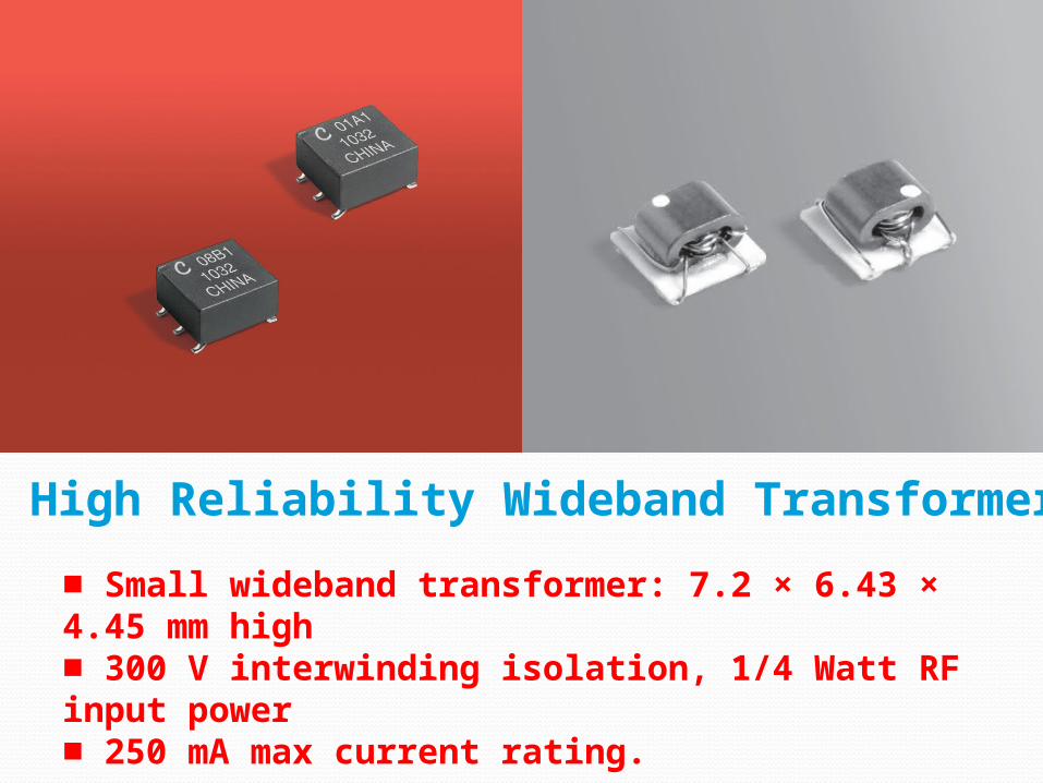
High Reliability Wideband Transformers
■ Small wideband transformer: 7.2 × 6.43 × 4.45 mm high■ 300 V interwinding isolation, 1/4 Watt RF input power■ 250 mA max current rating.

Core material FerriteTerminations tin-silver-copper over tin over nickel over phos bronze.Ambient temperature –55°C to +125°CStorage temperature Component: –55°C to +125°C.Tape and reel packaging: –55°C to +80°CResistance to soldering heat Max three 40 second reflows at+260°C, parts cooled to room temperature between cyclesMoisture Sensitivity Level (MSL) 1 (unlimited floor life at <30°C /85% relative humidity)Enhanced crush-resistant packaging 750/7″reelPlastic tape: 12 mm wide, 0.3 mm thick, 8 mm pocket spacing, 2.9 mm pocket depth
High Reliability Wideband Transformers
Designing of wide band transformers
In the design of these kinds of wide band transformers the primary reactance is usually around 5 times the primary impedance.

Impedances are determined by the source and load impedances to be interfaced by the transformer. Inasmuch as the transformer is essentially a loss less device, terminal voltages and impedance levels are ideally related as √ (Zin/Z out).
Input and Output Impedances
Usually defined by the high and low frequencies where the amplitude response drops 3 dB below that at mid-frequency. Bandwidth may also be defined at the high end, as that frequency where a specified value of VSWR is not exceeded. A typical specification value would be 1.25:1 (–19 dB return loss).
BAND WIDTH

Usually specified at mid-band, and typically on the order of 0.2 to 0.5 dB, depending on bandwidth and center frequency.
Insertion Loss

In some applications, the transformer insertion loss over a specified band must be held within certain limits. This tolerance value defines the flatness of response.
Flatness
This is the ratio, in dB, of reflected to incident power, and is essentially a measure of the quality of the transformer’s specified match to source or load impedance.
Return Loss (VSWR)

Return Loss/VSWR (1.0 - 65MHz)

Specifies the maximum voltage that can be applied between windings and between windings and case. In North Hills' transformers this is usually 500 or 1000 Vrms depending on case style.
Dielectric Withstanding Voltage

Most requirements dictate dc isolation between windings. Exceptions are devices such as coaxial adapters and phase inverters.
Isolation

WIDE BAND XMER’S

PN
Thank You