Embed Size (px)
Citation preview

Welcome
to
Practical
Session
Robot to be made
Chassis
Battery
DPDT Switch
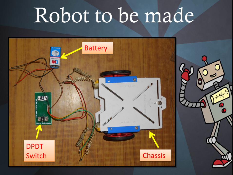
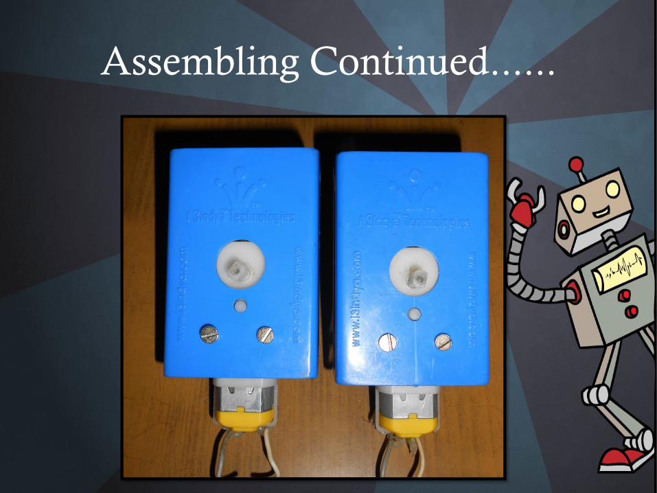
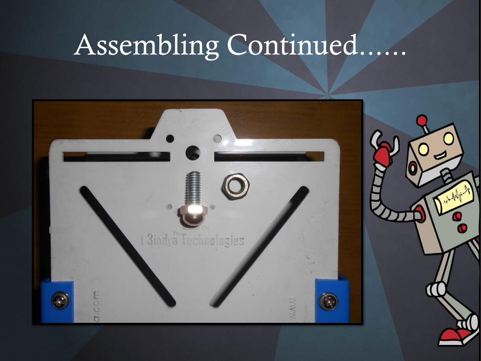
Assembling Continued......
MOTOR
Use these Screws ONLY
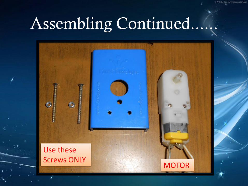
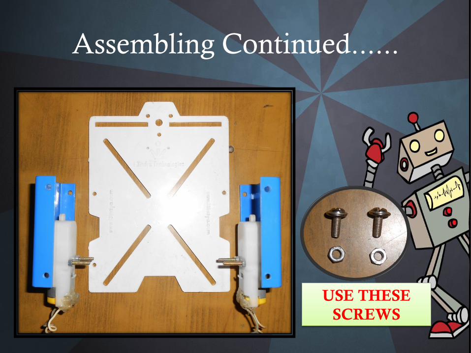
Assembling Continued......
Assembling Continued......
Assembling Continued......
USE THESE
SCREWS

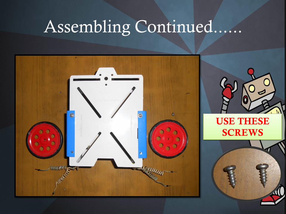
Assembling Continued......
Assembling Continued......
USE THESE
SCREWS
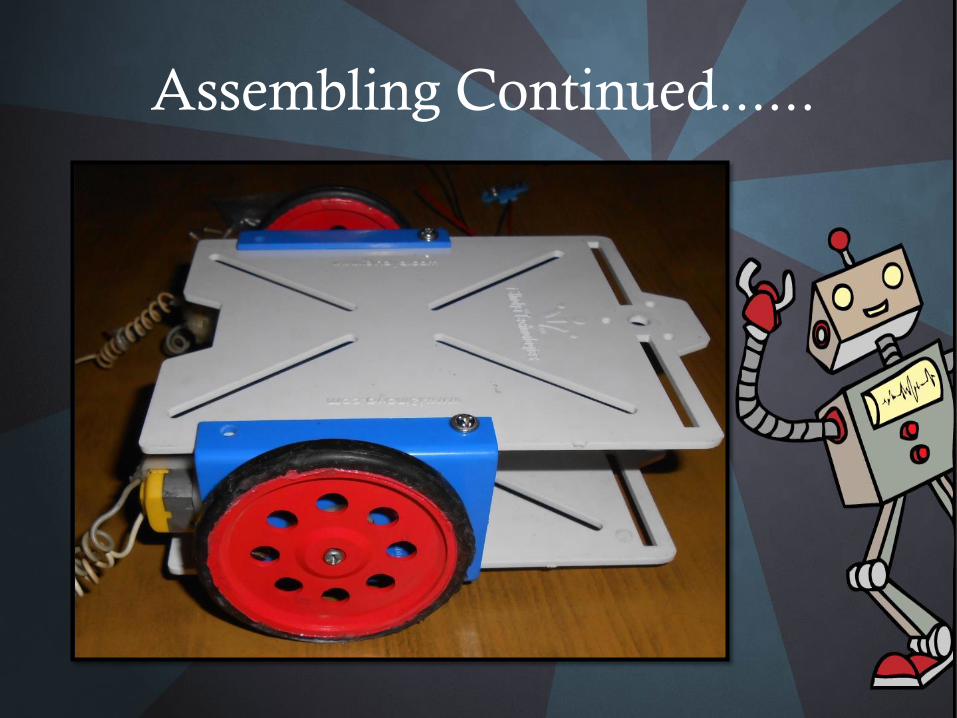
Assembling Continued......
Assembling Continued......
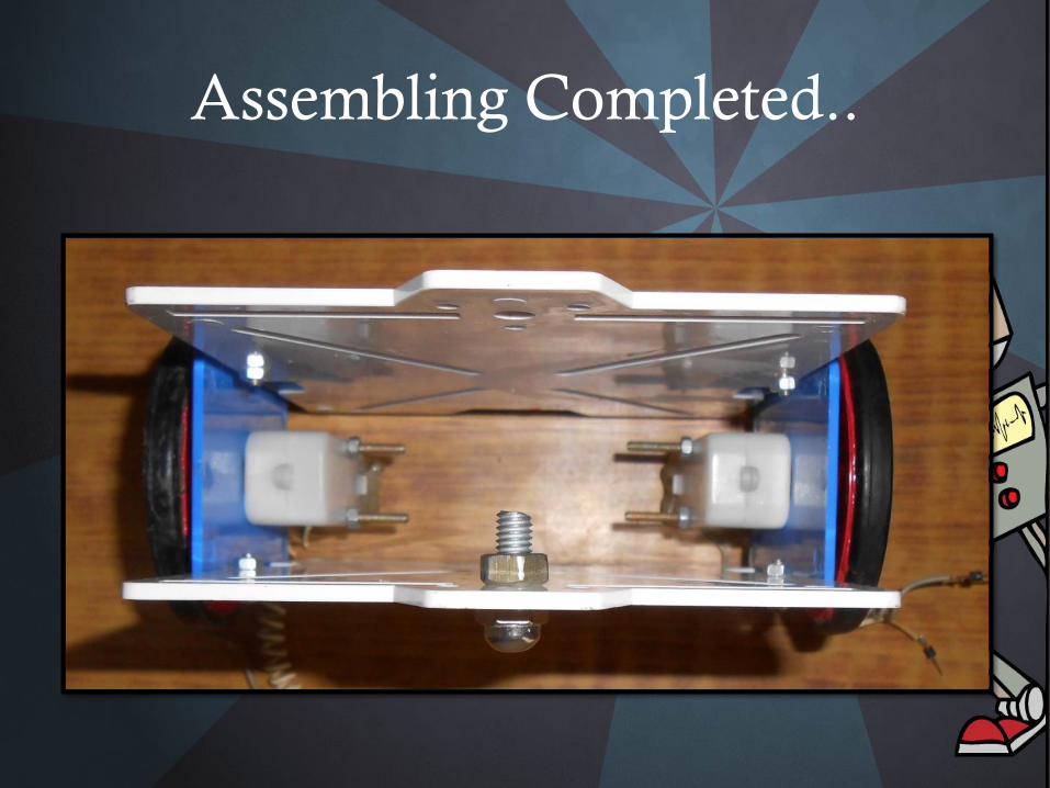
Assembling Completed..
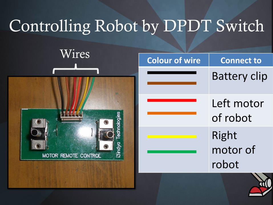
Controlling Robot by DPDT Switch
Colour of wire Connect to
Battery clip
Left motor of robot
Right motor of robot
Wires
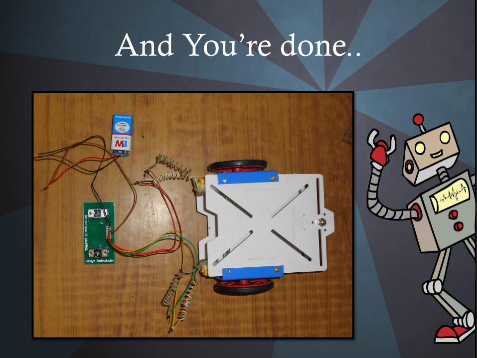
And You’re done..
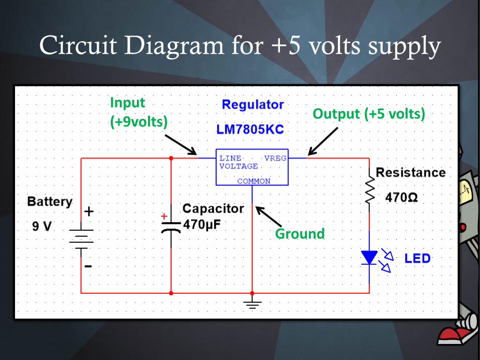
Circuit Diagram for +5 volts supply
+
-
Input(+9volts) Output (+5 volts)
Ground
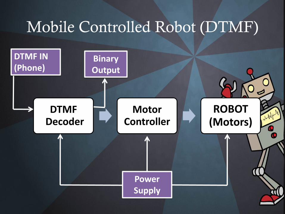
Mobile Controlled Robot (DTMF)
DTMFDecoder
Motor Controller
ROBOT(Motors)
DTMF IN(Phone)
Power Supply
Binary Output
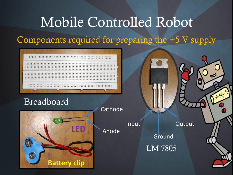
Mobile Controlled RobotComponents required for preparing the +5 V supply
Breadboard
LM 7805
Cathode
AnodeInput
Ground
OutputLED
Battery clip
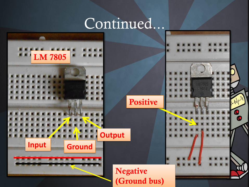
Continued...
Input Ground
Output
Positive
Negative
(Ground bus)
LM 7805
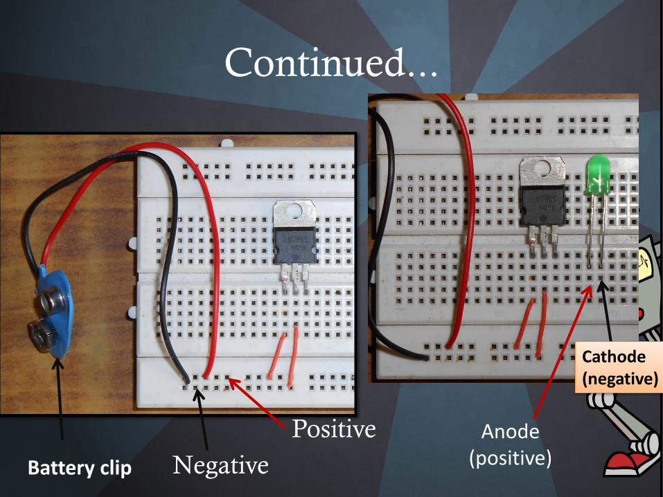
Continued...
Battery clip
Positive
Negative
Anode(positive)
Cathode(negative)
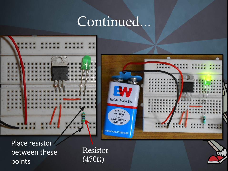
Continued...
Resistor
(470Ω)
Place resistor between these points
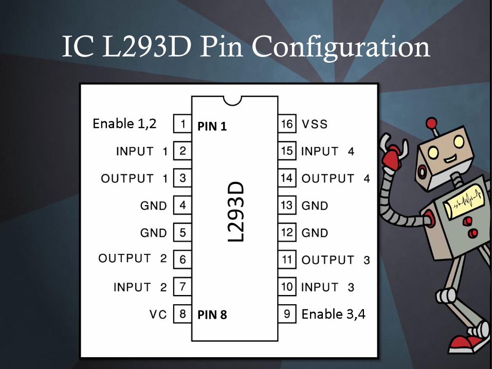
IC L293D Pin Configuration
L29
3D
PIN 1
PIN 8
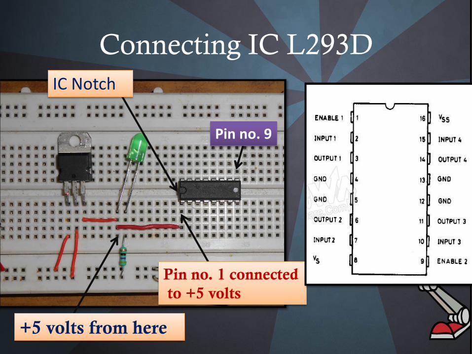
Connecting IC L293D
IC Notch
Pin no. 1 connected
to +5 volts
+5 volts from here
Pin no. 9
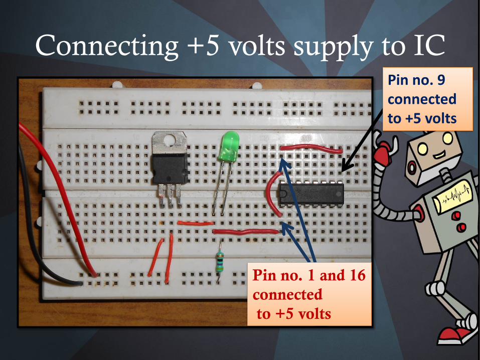
Connecting +5 volts supply to IC
Pin no. 1 and 16
connected
to +5 volts
Pin no. 9 connected to +5 volts
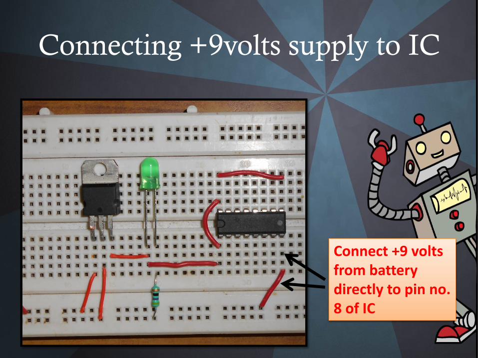
Connecting +9volts supply to IC
Connect +9 volts from battery directly to pin no. 8 of IC
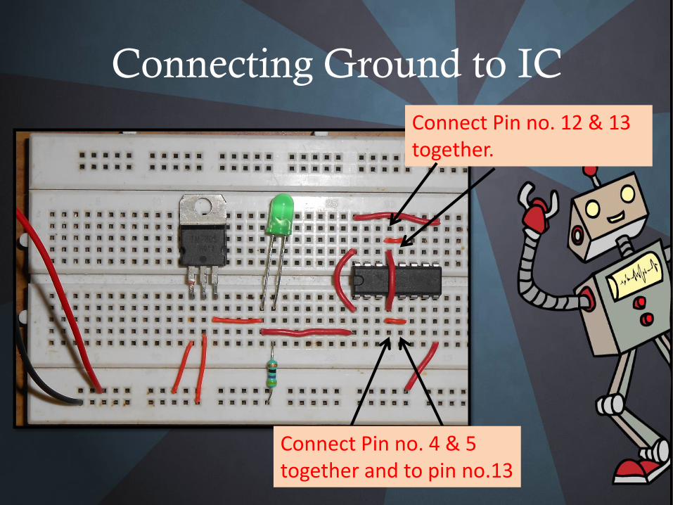
Connecting Ground to IC
Connect Pin no. 4 & 5 together and to pin no.13
Connect Pin no. 12 & 13 together.
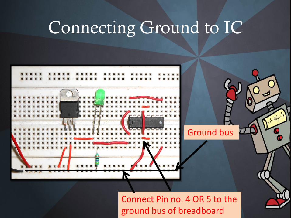
Connecting Ground to IC
Connect Pin no. 4 OR 5 to the ground bus of breadboard
Ground bus
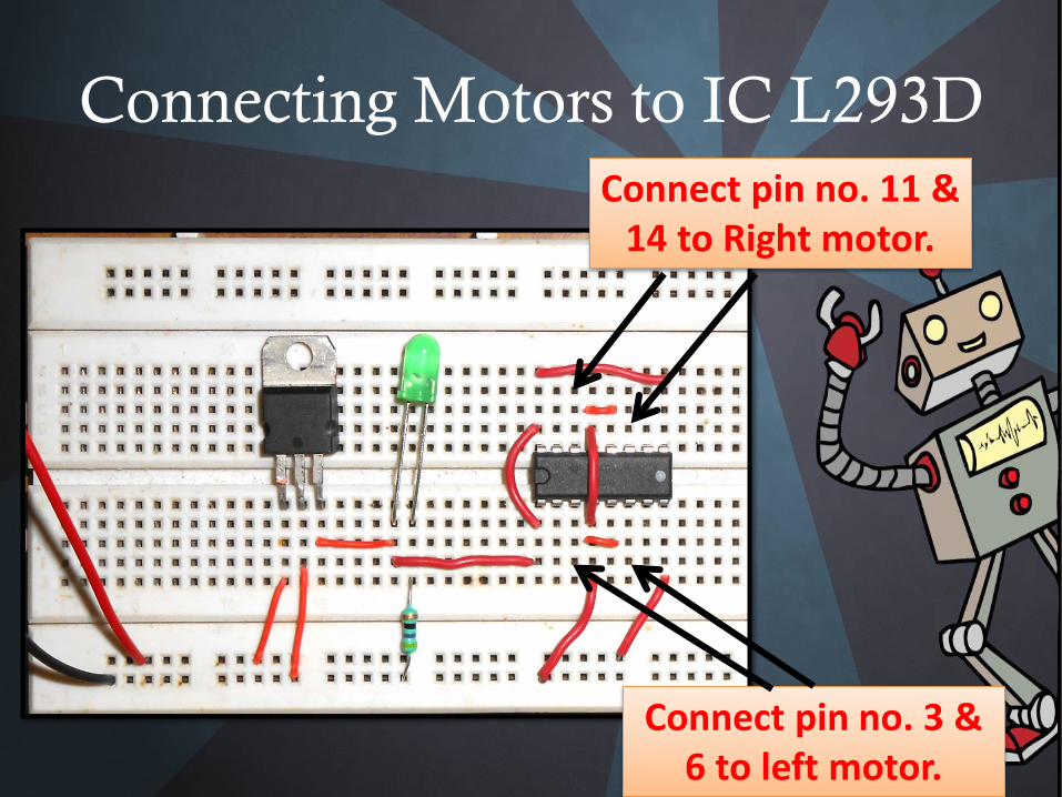
Connecting Motors to IC L293D
Connect pin no. 3 & 6 to left motor.
Connect pin no. 11 & 14 to Right motor.
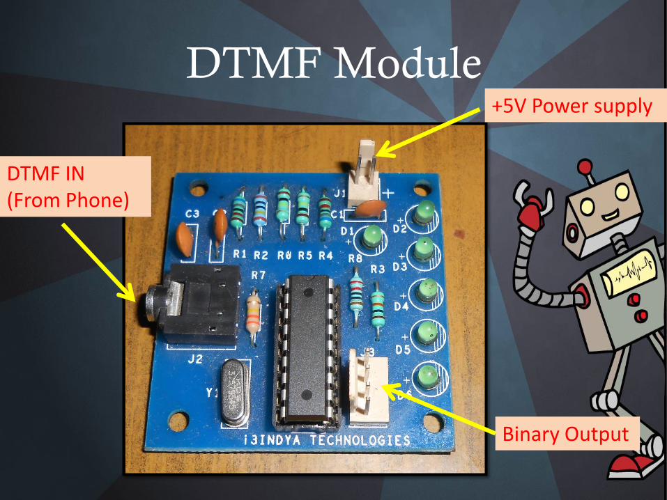
DTMF Module
DTMF IN (From Phone)
+5V Power supply
Binary Output
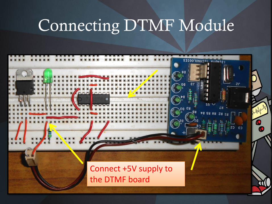
Connecting DTMF Module
Connect +5V supply to the DTMF board
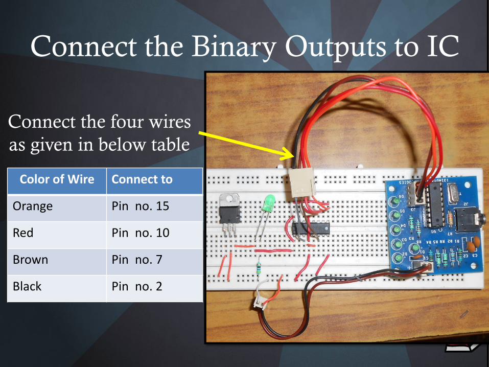
Connect the Binary Outputs to IC
Color of Wire Connect to
Orange Pin no. 15
Red Pin no. 10
Brown Pin no. 7
Black Pin no. 2
Connect the four wires
as given in below table
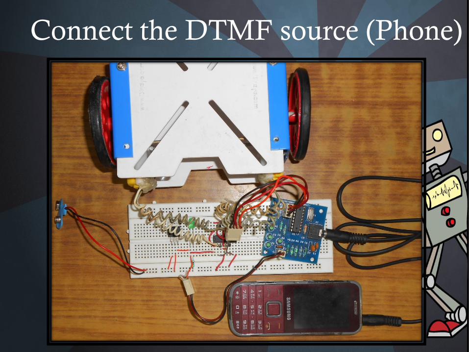
Connect the DTMF source (Phone)
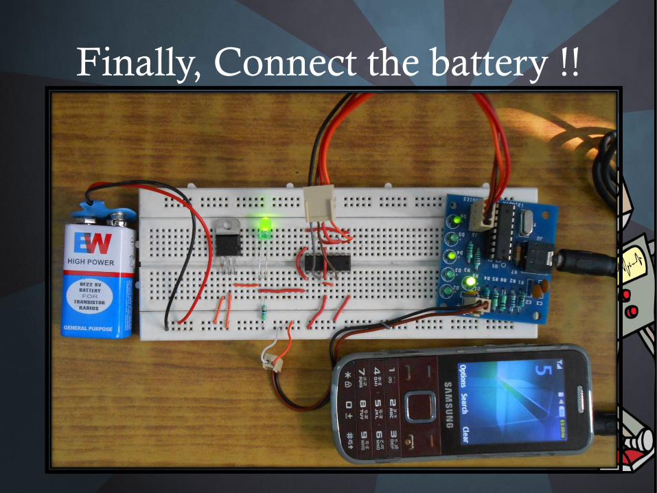
Finally, Connect the battery !!

Thank You !!!