Embed Size (px)
Citation preview


VTU Kinematics of Machines MODULE – 1 Notes [email protected]
1 | P a g e
KINEMATICS OF
MACHINES
BY:
G.S SHASHIDHARA.,DME,
BE, AMIE(I)
Email: [email protected]

VTU Kinematics of Machines MODULE – 1 Notes [email protected]
2 | P a g e
MODULE – 1
INTRODUCTION :
The study of a mechanism involves its analysis as well as
synthesis.
Analysis is the study of motions and forces concerning
different parts of an existing mechanism. Whereas
Synthesis involves the design of its different parts.
Mechanics: It is that branch of scientific analysis which
deals with motion, time and force. Kinematics is the study of motion, without considering
the forces which produce that motion. Kinematics of machines deals with the study of the relative motion of machine parts. It involves the study of position, displacement, velocity and acceleration of machine parts. Dynamics of machines involves the study of forces acting
on the machine parts and the motions resulting from these forces.
Plane motion: A body has plane motion, if all its points
move in planes which are parallel to some reference plane. A body with plane motion will have only three degrees of freedom. i.e., linear along two axes parallel to the reference plane and rotational/angular about the axis perpendicular to the reference plane. (eg. linear along X and Z and rotational about Y.)The reference plane is called plane of motion. Plane motion can be of three

VTU Kinematics of Machines MODULE – 1 Notes [email protected]
3 | P a g e
types. 1) Translation 2) rotation and 3) combination of translation and rotation. Translation: A body has translation if it moves so that
all straight lines in the body move to parallel positions. Rectilinear translation is a motion wherein all points of the body move in straight lie paths. Eg. The slider in slider crank mechanism has rectilinear translation. (link 4 in fig.1.1)
Translation, in which points in a body move along curved paths, is called curvilinear translation. The tie rod connecting the wheels of a steam locomotive has curvilinear translation. (link 3 in fig.1.2)
Rotation: In rotation, all points in a body remain at fixed
distances from a line which is perpendicular to the plane

VTU Kinematics of Machines MODULE – 1 Notes [email protected]
4 | P a g e
of rotation. This line is the axis of rotation and points in the body describe circular paths about it. (Eg. link 2 in Fig.1.1 and links 2 & 4 in Fig.1.2)
Translation and rotation: It is the combination of both
translation and rotation which is exhibited by many machine parts. (Eg. link 3 in Fig.1.1)
Link or element: It is the name given to any body
which has motion relative to another. All materials have some elasticity. A rigid link is one, whose deformations are so small that they can be neglected in determining the motion parameters of the link. A link or element need not to be rigid body, but it must be a resistant body. A body is said to be a resistant body if it is capable of transmitting the required forces with negligible deformation. Thus a link should have the following two characteristics:
1. It should have relative motion. 2. It must be resistant body.
TYPES OF LINKS: In order to transmit motion, driver and the follower may be connected by the following three types of links:
(1) Rigid link: A rigid link is one which does not
undergo any deformation while transmitting motion. Strictly speaking, rigid links do not exist. However, as the deformation of a connecting rod, crank etc. of a reciprocating steam engine is not appreciable, they can be considered as rigid links.

VTU Kinematics of Machines MODULE – 1 Notes [email protected]
5 | P a g e
(2) Flexible link: A flexible link is one which is partly
deformed in a manner not to affect the transmission of motion. Eg: belts, ropes, chains and wires are flexible links and transmit tensile forces only.
(3) Fluid link: A fluid link is one which is formed by
having a fluid in a receptacle and the motion is transmitted through the fluid by pressure or compression only. Eg: hydraulic presses, hydraulic jacks and fluid brakes.
Fig.1.3
Binary link: Link which is connected to other links at
two points. (Fig.1.3 a) Ternary link: Link which is connected to other links at
three points. (Fig.1.3 b)

VTU Kinematics of Machines MODULE – 1 Notes [email protected]
6 | P a g e
Quaternary link: Link which is connected to other links
at four points. (Fig1.3 c) Pairing elements: the geometrical forms by which two
members of a mechanism are joined together, so that the relative motion between these two is consistent are known as pairing elements and the pair so formed is called kinematic pair. Each individual link of a mechanism forms a pairing element.
Fig.1.4 Kinematic pair Fig.1.5
Degrees of freedom (DOF): It is the number of
independent coordinates required to describe the position of a body in space. A free body in space (fig 1.5) can have six degrees of freedom. I.e., linear positions along x, y and z axes and rotational/angular positions with respect to x, y and z axes. In a kinematic pair, depending on the constraints imposed on the motion, the links may loose some of the six degrees of freedom. Each part of a machine, which moves relative to some other part, is known as a kinematic link (or simply link)

VTU Kinematics of Machines MODULE – 1 Notes [email protected]
7 | P a g e
or element. A link may consist of several parts, which are
rigidly fastened together, so that they do not move relative to one another. Mechanism: A mechanism is a combination of rigid or resistant bodies so formed and connected that they move upon each other with definite relative motion. such as the crank- connecting rod mechanism of the I.C. engines, steering mechanisms of automobiles……. etc. Machine: machine is a device which receives energy and transforms it into some useful work. A machine consists of a number of parts or bodies with successfully constrained motion which is used to transmit or transform motion to do some useful work. A machine is a mechanism or collection of mechanisms which transmit force from the source of power to the resistance to be overcome. Structure: It is an assemblage of a number of resistant bodies (known as members) having no relative motion between them and meant for carrying loads having straining action. Eg: railway bridge, a roof truss, machine frames etc.

VTU Kinematics of Machines MODULE – 1 Notes [email protected]
8 | P a g e
Difference between a Machine and Structure:
MACHINE STRUCTURE
1. The parts of a machine moves relative to one another.
1. The members of a structure do not move relative to one another.
2. A machine transforms the available energy into some useful work.
2. In a structure no energy is transformed into useful work.
3. The link of a machine may transmit both power and motion. Eg: Lathe, shaper, steam engine etc.
3. The members of a structure transmit forces only. Eg: Railway bridges, roof trusses, machine frame.
Difference between a Machine and Mechanism
MACHINE MECHANISM
1. Machine modifies mechanical work.
1. Mechanism transmits and modifies motion.
2. A machine is a practical development of any mechanism.
2. A mechanism is a part of a machine.
3. A machine may have number of mechanisms for transmitting mechanical work or power. Eg: Lathe, Shaper, Steam engine etc.
3. A mechanism is the skeleton outline of the machine to produce motion between various links. Eg: Clock work, type-writer, an indicator to draw P.V diagrams of an engine etc.


VTU Kinematics of Machines MODULE – 1 Notes [email protected]
9 | P a g e
Rigid Body: is that body whose changes in shape are
negligible compared with its overall dimensions or with the changes in position of the body as a whole, such as rigid link, rigid disc…..etc. Kinematic pair: When two elements or links are connected together in such a way that their relative motion is constrained, form a kinematic pair. Therefore, in order to compel a body to move in a definite path, it must be paired with another. If the constraint is not complete (not definite path) the pair is termed as incomplete or unsuccessful. Kinematic Pair The two links or elements of a machine, when in contact with each other, are said to form a pair. If the relative motion between them is completely or successfully constrained (i.e. in a definite direction), the pair is known as kinematic pair.
Types of kinematic pairs: (i) Based on nature of contact between elements: (a) Lower pair. If the joint by which two members are
connected has surface contact, the pair is known as lower pair. Eg. pin joints, shaft rotating in bush, slider in slider crank mechanism.

VTU Kinematics of Machines MODULE – 1 Notes [email protected]
10 | P a g e
Fig.1.6 Lower pairs
(b) Higher pair. If the contact between the pairing
elements takes place at a point or along a line, such as in a ball bearing or between two gear teeth in contact, it is known as a higher pair.
Fig.1.7 Higher pairs

VTU Kinematics of Machines MODULE – 1 Notes [email protected]
11 | P a g e
(ii) Based on relative motion between pairing elements: (a) Sliding pair : Sliding pair is constituted by two
elements so connected that one is constrained to have a sliding motion relative to the other. DOF = 1 Eg: rectangular rod in a rectangular hole, the piston and cylinder of an engine, the cross-head and guides of a steam engine, the ram and its guides in a shaper, the tailstock on the lathe bed etc. (b) Turning pair (revolute pair). When connections
of the two elements are such that only a constrained motion of rotation of one element with respect to the other is possible, the pair constitutes a turning pair. DOF = 1 Eg: circular shaft revolving inside a bearing, a shaft with a collar at both ends revolving in a circular hole, cycle wheels revolving over their axles etc. (c) Cylindrical pair. If the relative motion between the
pairing elements is the combination of turning and sliding, then it is called as cylindrical pair. DOF = 2
Fig.1.8 Sliding pair Fig.1.9 Turning pair Fig.1.10 Cylindrical pair


VTU Kinematics of Machines MODULE – 1 Notes [email protected]
12 | P a g e
(d) Rolling pair. When the pairing elements have
rolling contact, the pair formed is called rolling pair. Eg. Bearings, Belt and pulley. DOF = 1 Eg: rolling wheel on a flat surface, ball and roller bearings etc.
Fig.1.11 (a) Ball bearing Fig.1.11(b) Belt and pulley (e) Spherical pair. A spherical pair will have surface
contact and three degrees of freedom. Eg. Ball and socket joint. DOF = 3 Eg: ball and socket joint, a mirror attachment of vehicles etc.
Picture of ball and socket joint.
(f) Helical pair or screw pair. When the nature of
contact between the elements of a pair is such that one

VTU Kinematics of Machines MODULE – 1 Notes [email protected]
13 | P a g e
element can turn about the other by screw threads, it is known as screw pair. Eg. Nut and bolt. DOF = 1 Eg: lead screw and the nut of a lathe, a bolt with a nut, a screw with the nut of a jack.
Fig.1.12 Ball and socket joint Fig.1.13 Screw pair
(iii) Based on the nature of mechanical constraint. (a) Closed pair. Elements of pairs held together
mechanically due to their geometry constitute a closed pair. They are also called form-closed or self-closed pair. All the lower pairs and some of the higher pairs are closed pairs. A cam and follower pair(higher pair) and screw pair (lower pair) belong to the closed pair. (b) Unclosed or force closed pair. Elements of pairs
held together by the action of external forces constitute unclosed or force closed pair .Eg. Cam and follower.

VTU Kinematics of Machines MODULE – 1 Notes [email protected]
14 | P a g e
Fig.1.14 Closed pair Fig. 1.15 Force closed pair (cam & follower)
Constrained motion: In a kinematic pair, if one
element has got only one definite motion relative to the other, then the motion is called constrained motion. (a) Completely constrained motion. If the
constrained motion is achieved by the pairing elements themselves, then it is called completely constrained motion. When the motion between a pair is limited to a definite direction irrespective of the direction of force applied, then the motion is called completely constrained motion. Eg: piston and cylinder (in a steam engine) form a pair and motion of the piston is limited to a definite direction (i.e., it will only reciprocate) relative to the cylinder irrespective of the direction of motion of the crank.

VTU Kinematics of Machines MODULE – 1 Notes [email protected]
15 | P a g e
Fig.1.16 Completely constrained motion
(b) Incompletely constrained motion. When relative
motion between pairing elements takes place in more than one direction, it is called incompletely constrained motion. The change in the direction of impressed force may alter the direction of relative motion between the pair. Eg. Shaft in a circular hole. (it may either rotate or slide in a hole. These both motions have no relationship with the other).
Fig.1.17 Incompletely constrained motion (c) Successfully constrained motion. When the
motion between the elements, forming a pair, is such that the constrained motion is not completed by itself, but by some other means, then the motion is called successfully constrained motion. If constrained motion is not achieved

VTU Kinematics of Machines MODULE – 1 Notes [email protected]
16 | P a g e
by the pairing elements themselves, but by some other means, then, it is called successfully constrained motion. Eg. Foot step bearing, where shaft is constrained from moving upwards, by its self weight.
Fig.1.18 Foot strep bearing
Kinematic chain: A kinematic chain is a group of links
either joined together or arranged in a manner that permits them to move relative to one another. If the links are connected in such a way that no motion is possible, it results in a locked chain or structure.
Fig.1.19 Locked chain or structure


VTU Kinematics of Machines MODULE – 1 Notes [email protected]
17 | P a g e
Mechanism: A mechanism is a constrained kinematic
chain. This means that the motion of any one link in the kinematic chain will give a definite and predictable motion relative to each of the others. Usually one of the links of the kinematic chain is fixed in a mechanism.
Fig.1.20 Slider crank and four bar mechanisms.
If, for a particular position of a link of the chain, the positions of each of the other links of the chain can not be predicted, then it is called as unconstrained kinematic chain and it is not mechanism.
Fig.1.21 Unconstrained kinematic chain
Machine: A machine is a mechanism or collection of
mechanisms, which transmit force from the source of power to the resistance to be overcome. Though all machines are mechanisms, all mechanisms are not machines. Many instruments are mechanisms but are not machines, because they do no useful work nor do they transform energy. Eg. Mechanical clock, drafter.

VTU Kinematics of Machines MODULE – 1 Notes [email protected]
18 | P a g e
Fig.1.21 Drafter
Planar mechanisms: When all the links of a mechanism
have plane motion, it is called as a planar mechanism. All the links in a planar mechanism move in planes parallel to the reference plane. Degrees of freedom/mobility of a mechanism: It is
the number of inputs (number of independent coordinates) required to describe the configuration or

VTU Kinematics of Machines MODULE – 1 Notes [email protected]
19 | P a g e
position of all the links of the mechanism, with respect to the fixed link at any given instant. An unconstrained rigid body moving in space can describe following independent motions:
1. Translational motions along any three mutually perpendicular axes x, y and z.
2. Rotational motions about these axes Thus a rigid body possesses six degrees of freedom. The connection of a link with another imposes certain constraints on their relative motion. The number of restraints can never be zero (joint is disconnected) or six (joint becomes solid). Degrees of freedom of a pair is defined as the number of independent relative motions, both translational and rotational. A pair can have degrees of freedom = 6 – number of restraints.
Grubler’s equation: Number of degrees of freedom of
a mechanism is given by F = 3(n-1)-2l-h.

VTU Kinematics of Machines MODULE – 1 Notes [email protected]
20 | P a g e
Where, F = Degrees of freedom n = Number of links = n2 + n3 +……+nj, where, n2 = number of binary links, n3 = number of ternary links…etc. l = Number of lower pairs, which is obtained by counting the number of joints. If more than two links are joined together at any point, then, one additional lower pair is to be considered for every additional link. h = Number of higher pairs
Examples of determination of degrees of freedom of planar mechanisms: (i)
F = 3(n-1)-2l-h Here, n2 = 4, n = 4, l = 4 and h = 0. F = 3(4-1)-2(4) = 1 I.e., one input to any one link will result in definite motion of all the links.

VTU Kinematics of Machines MODULE – 1 Notes [email protected]
21 | P a g e
(ii)
F = 3(n-1)-2l-h Here, n2 = 5, n = 5, l = 5 and h = 0. F = 3(5-1)-2(5) = 2 I.e., two inputs to any two links are required to yield definite motions in all the links. (iii)
F = 3(n-1)-2l-h Here, n2 = 4, n3 =2, n = 6, l = 7 and h = 0. F = 3(6-1)-2(7) = 1 I.e., one input to any one link will result in definite motion of all the links.

VTU Kinematics of Machines MODULE – 1 Notes [email protected]
22 | P a g e
(iv)
F = 3(n-1)-2l-h Here, n2 = 5, n3 =1, n = 6, l = 7 (at the intersection of 2, 3 and 4, two lower pairs are to be considered) and h = 0. F = 3(6-1)-2(7) = 1 (v)
F = 3(n-1)-2l-h Here, n = 11, l = 15 (two lower pairs at the intersection of 3, 4, 6; 2, 4, 5; 5, 7, 8; 8, 10, 11) and h = 0. F = 3(11-1)-2(15) = 0
VTU Kinematics of Machines MODULE – 1 Notes [email protected]
23 | P a g e
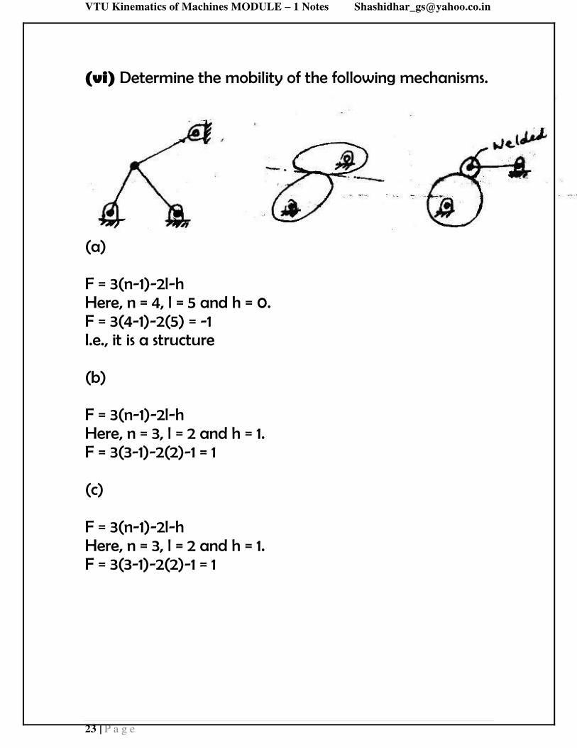
(vi) Determine the mobility of the following mechanisms.
(a) F = 3(n-1)-2l-h Here, n = 4, l = 5 and h = 0. F = 3(4-1)-2(5) = -1 I.e., it is a structure (b) F = 3(n-1)-2l-h Here, n = 3, l = 2 and h = 1. F = 3(3-1)-2(2)-1 = 1 (c) F = 3(n-1)-2l-h Here, n = 3, l = 2 and h = 1. F = 3(3-1)-2(2)-1 = 1


VTU Kinematics of Machines MODULE – 1 Notes [email protected]
24 | P a g e
Inversions of mechanism: A mechanism is one in which
one of the links of a kinematic chain is fixed. Different mechanisms can be obtained by fixing different links of the same kinematic chain. These are called as inversions of the mechanism. By changing the fixed link, the number of mechanisms which can be obtained is equal to the number of links. Excepting the original mechanism, all other mechanisms will be known as inversions of original mechanism. The inversion of a mechanism does not change the motion of its links relative to each other. Four bar chain:
Fig 1.22 Four bar chain
One of the most useful and most common mechanisms is the four-bar linkage. In this mechanism, the link which can make complete rotation is known as crank (link 2). The link which oscillates is known as rocker or lever (link 4). And the link connecting these two is known as coupler (link 3). Link 1 is the frame.

VTU Kinematics of Machines MODULE – 1 Notes [email protected]
25 | P a g e
Inversions of four bar chain:
Fig.1.23 Inversions of four bar chain.

VTU Kinematics of Machines MODULE – 1 Notes [email protected]
26 | P a g e
Crank-rocker mechanism: In this mechanism, either
link 1 or link 3 is fixed. Link 2 (crank) rotates completely and link 4 (rocker) oscillates. It is similar to (a) or (b) of fig.1.23.
Fig.1.24
Drag link mechanism. Here link 2 is fixed and both
links 1 and 4 make complete rotation but with different velocities. This is similar to 1.23(c).
Fig.1.25

VTU Kinematics of Machines MODULE – 1 Notes [email protected]
27 | P a g e
Double crank mechanism (Coupling rod of Locomotive) . This is one type of drag link mechanism,
where, links 1& 3 are equal and parallel and links 2 & 4 are equal and parallel. When AB rotates about A, the crank DC rotates about D. This mechanism is used for coupling locomotive wheels. Since links AB and CD work as cranks, this mechanism is also known as double crank or crank-crank or drag-crank mechanism.
Fig.1.26
Double rocker mechanism. In this mechanism, link 4 is
fixed. Link 2 makes complete rotation, whereas links 3 & 4 oscillate (Fig.1.23d) Slider crank chain: This is a kinematic chain having
four links. It has one sliding pair and three turning pairs. Link 2 has rotary motion and is called crank. Link 3 has got combined rotary and reciprocating motion and is called connecting rod. Link 4 has reciprocating motion and is called slider. Link 1 is frame (fixed). This mechanism is used to convert rotary motion to reciprocating and vice versa.

VTU Kinematics of Machines MODULE – 1 Notes [email protected]
28 | P a g e
Fig1.27
Inversions of slider crank chain: Inversions of slider
crank mechanism is obtained by fixing links 2, 3 and 4.
(a) crank fixed (b) connecting rod fixed (c) slider fixed
Fig.1.28
Rotary engine (Gnome Engine) – I inversion of slider crank mechanism. (crank fixed) It is a rotary cylinder V-type internal combustion engine. Sometimes back, rotary internal combustion engines were used in aviation. But now-a-days gas turbines are used in its place. It consists of seven cylinders in one plane and all revolves about fixed centre A as shown in Fig. 1.29, while the crank OA (link 2) is fixed. In this mechanism, when the connecting rod (link 4) from pistons are connected to A

VTU Kinematics of Machines MODULE – 1 Notes [email protected]
29 | P a g e
rotates, the piston (link 3) reciprocates inside the cylinders forming link 1.
Fig. 1.29
Whitworth quick return motion mechanism–I inversion of slider crank mechanism. This is first inversion of slider mechanism, where, crank 1 is fixed. Input is given to link 2, which moves at constant speed. Point C of the mechanism is connected to the tool post D of the machine. During cutting stroke, tool post moves from D′ to D′′. The corresponding positions of C are C′ and C′′ as shown in the fig. 1.30. For the point C to move from C′ to C′′, point B moves from B′ to B′′, in anti-clockwise direction. I.E., cutting stroke takes place when input link moves through angle B′O B′′ in anticlockwise direction and return stroke takes place

VTU Kinematics of Machines MODULE – 1 Notes [email protected]
30 | P a g e
when input link moves through angle B′′O B′ in anti-clockwise direction.
Fig.1.30
Crank and slotted lever quick return motion mechanism – II inversion of slider crank mechanism (connecting rod fixed). This mechanism is mostly used in shaping machines, slotting machines and in rotary internal combustion engines. In this mechanism, the link AC (i.e. link 3) forming the turning pair is fixed, as shown in Fig. 1.31. The link 3 corresponds to the connecting rod of a reciprocating steam engine. The driving crank CB revolves with uniform angular speed about the fixed centre C. A sliding block attached to the crank pin at B slides along the slotted bar AP and thus causes AP to oscillate about the pivoted point A. A short link PR transmits the motion from AP to the ram which carries the tool and reciprocates along the

VTU Kinematics of Machines MODULE – 1 Notes [email protected]
31 | P a g e
line of stroke . The line of stroke of the ram (i.e. ) is perpendicular to AC produced.
Fig.1.31
VTU Kinematics of Machines MODULE – 1 Notes [email protected]
32 | P a g e
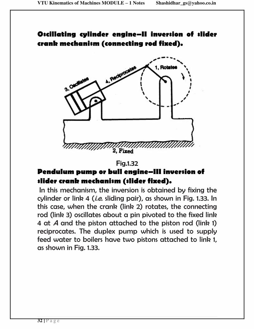
Oscillating cylinder engine–II inversion of slider crank mechanism (connecting rod fixed).
Fig.1.32
Pendulum pump or bull engine–III inversion of slider crank mechanism (slider fixed). In this mechanism, the inversion is obtained by fixing the cylinder or link 4 (i.e. sliding pair), as shown in Fig. 1.33. In this case, when the crank (link 2) rotates, the connecting rod (link 3) oscillates about a pin pivoted to the fixed link 4 at A and the piston attached to the piston rod (link 1) reciprocates. The duplex pump which is used to supply feed water to boilers have two pistons attached to link 1, as shown in Fig. 1.33.

VTU Kinematics of Machines MODULE – 1 Notes [email protected]
33 | P a g e
Fig.1.33
Double slider crank chain: It is a kinematic chain
consisting of two turning pairs and two sliding pairs. Scotch –Yoke mechanism. This mechanism is used for converting rotary motion into a reciprocating motion. Turning pairs – 1&2, 2&3; Sliding pairs – 3&4, 4&1.

VTU Kinematics of Machines MODULE – 1 Notes [email protected]
34 | P a g e
Fig.1.34
Hand pump:
Hand pump is an application of fourth inversion. The slotted link shape is given to the slider and vice versa.

VTU Kinematics of Machines MODULE – 1 Notes [email protected]
35 | P a g e
Since the slider i.e., link 4 is fixed, it is possible for the link 1 to reciprocate along a vertical straight line. At the same time, link 2 will rotate and link 3 will oscillate. Inversions of double slider crank mechanism: Elliptical trammel. This is a device which is used for
generating an elliptical profile.
Fig.1.35
In fig. 1.35, if AC = p and BC = q, then, x = q.cosθ and y = p.sinθ.
Rearranging , + = Ɵ + � Ɵ = 1 This is
the equation of an ellipse. The path traced by point C is an ellipse, with major axis and minor axis equal to 2p and 2q respectively.

VTU Kinematics of Machines MODULE – 1 Notes [email protected]
36 | P a g e
Oldham coupling. This is an inversion of double slider
crank mechanism, An oldham's coupling is used for connecting two parallel shafts whose axes are at a small distance apart. The shafts are coupled in such a way that if one shaft rotates, the other shaft also rotates at the same speed.
Fig.1.36
Straight line motion mechanisms
Straight line motion mechanisms are mechanisms, having a point that moves along a straight line, or nearly along a straight line, without being guided by a plane surface.
Condition for exact straight line motion:
If point B (fig.1.37) moves on the circumference of a circle with center O and radius OA, then, point C, which is an extension of AB traces a straight line perpendicular to AO, provided product of AB and AC is constant.

VTU Kinematics of Machines MODULE – 1 Notes [email protected]
37 | P a g e
Fig.1.37
Locus of pt.C will be a straight line, ┴ to AE if, AB AC is constant
Proof:
AEC ABD
=
×
but AD constant.
AE constant., if AB AC constant.

VTU Kinematics of Machines MODULE – 1 Notes [email protected]
38 | P a g e
Peaucellier exact straight line motion mechanism:
Fig.1.38
Here, AE is the input link and point E moves along a circular path of radius AE = AB. Also, EC = ED = PC = PD and BC = BD. Point P of the mechanism moves along exact straight line, perpendicular to BA extended.

VTU Kinematics of Machines MODULE – 1 Notes [email protected]
39 | P a g e
To prove B, E and P lie on same straight line:
Triangles BCD, ECD and PCD are all isosceles triangles having common base CD and apex points being B, E and P. Therefore points B, E and P always lie on the perpendicular bisector of CD. Hence these three points always lie on the same straight line.
To prove product of BE and BP is constant.
In triangles BFC and PFC,
= + and = +
− = - = + − = ×
But since BC and PC are constants, product of BP and BE is constant, which is the condition for exact straight line motion. Thus point P always moves along a straight line perpendicular to BA as shown in the fig.1.38.
Approximate straight line motion mechanism: A
few four bar mechanisms with certain modifications provide approximate straight line motions.

VTU Kinematics of Machines MODULE – 1 Notes [email protected]
40 | P a g e
Robert’s mechanism
Fig.1.39
This is a four bar mechanism, where, PCD is a single integral link. Also, dimensions AC, BD, CP and PD are all equal. Point P of the mechanism moves very nearly along line AB.

VTU Kinematics of Machines MODULE – 1 Notes [email protected]
41 | P a g e
Intermittent motion mechanisms
An intermittent-motion mechanism is a linkage which converts continuous motion into intermittent motion. These mechanisms are commonly used for indexing in machine tools.
Geneva wheel mechanism
Fig.1.40
In the mechanism shown (Fig.1.40), link A is driver and it contains a pin which engages with the slots in the driven link B. The slots are positioned in such a manner, that the pin enters and leaves them tangentially avoiding impact loading during transmission of motion. In the mechanism shown, the driven member makes one-fourth of a

VTU Kinematics of Machines MODULE – 1 Notes [email protected]
42 | P a g e
revolution for each revolution of the driver. The locking plate, which is mounted on the driver, prevents the driven member from rotating except during the indexing period.
Ratchet and pawl mechanism:
Fig.1.41
Ratchets are used to transform motion of rotation or translation into intermittent rotation or translation. In the fig.1.41, A is the ratchet wheel and C is the pawl. As lever B is made

VTU Kinematics of Machines MODULE – 1 Notes [email protected]
43 | P a g e
to oscillate, the ratchet wheel will rotate anticlockwise with an intermittent motion. A holding pawl D is provided to prevent the reverse motion of ratchet wheel.
Other mechanisms:
Toggle mechanism:
Fig.1.42
Toggle mechanisms are used, where large resistances are to be overcome through short distances. Here, effort applied will be small but acts over large distance. In the mechanism shown in fig.1.42, 2 is the input link, to which, power is supplied and 6 is the output link, which has to overcome external resistance. Links 4 and 5 are of equal length.

VTU Kinematics of Machines MODULE – 1 Notes [email protected]
44 | P a g e
Considering the equilibrium condition of slider 6,
tan α = ⁄
F = 2 P tan α
For small angles of α, F (effort) is much smaller than P(resistance).
This mechanism is used in rock crushers, presses, riveting machines etc.

VTU Kinematics of Machines MODULE – 1 Notes [email protected]
45 | P a g e
Pantograph
Pantographs are used for reducing or enlarging drawings and maps. They are also used for guiding cutting tools or torches to fabricate complicated shapes.
Fig.1.43
In the mechanism shown in fig.1.43 path traced by point A will be magnified by point E to scale, as discussed below.
In the mechanism shown, AB = CD; AD =BC and OAE lie on a straight line.
When point A moves to A , E moves to E and
OAE also lies on a straight line.
From the fig.1.43,
ODA OCE and ODAOC E .

VTU Kinematics of Machines MODULE – 1 Notes [email protected]
46 | P a g e
= = � ′′ = ′ ′ = ′ ′ ′ ′
But, = ′ ′ ; ∴ = ′ ′ ; ∴ ∆ ′ ≡ ∆ ′
′║ ′and
′′ = =
′ = ′
Where is the magnification factor.

VTU Kinematics of Machines MODULE – 1 Notes [email protected]
47 | P a g e
STEERING MECHANISMS
Hooke’s joint (Universal joints)
Hooke’s joints is used to connect two nonparallel but intersecting shafts. In its basic shape, it has two U –shaped yokes ‘a’ and ‘b’ and a center block or cross-shaped piece, C. (fig.1.44(a))
The universal joint can transmit power between two shafts intersecting at around 300 angles (α). However, the angular velocity ratio is not uniform during the cycle of operation. The amount of fluctuation depends on the angle (α) between the two shafts. For uniform transmission of motion, a pair of universal joints should be used (fig.1.44(b)). Intermediate shaft 3 connects input shaft 1 and output shaft 2 with two universal joints. The angle α between 1 and 2 is equal to angle α between 2 and 3. When shaft 1 has uniform rotation, shaft 3 varies in speed; however, this variation is compensated by the universal joint between shafts 2 and 3. One of the important applications of universal joint is in automobiles, where it is used to transmit power from engine to the wheel axle.

VTU Kinematics of Machines MODULE – 1 Notes [email protected]
48 | P a g e
Fig.1.44(a)
Fig.1.44(b): Hooke’s joint
Applications of Hooke’s joint:
1. Transmission of power from the engine gear box to the rear axle of the automobile.
2. Transmission of drives to different spindle in multiple drilling machine.
3. Transmission of torque to the rolls in the rolling mills. 4. Knee joint in a milling machine.
Steering gear mechanism
The steering mechanism is used in automobiles for changing the directions of the wheel axles with reference to the chassis, so

VTU Kinematics of Machines MODULE – 1 Notes [email protected]
49 | P a g e
as to move the automobile in the desired path. Usually, the two back wheels will have a common axis, which is fixed in direction with reference to the chassis and the steering is done by means of front wheels.
In automobiles, the front wheels are placed over the front axles (stub axles), which are pivoted at the points A & B as shown in the fig.1.45. When the vehicle takes a turn, the front wheels, along with the stub axles turn about the pivoted points. The back axle and the back wheels remain straight.
Always there should be absolute rolling contact between the wheels and the road surface. Any sliding motion will cause wear of tyres. When a vehicle is taking turn, absolute rolling motion of the wheels on the road surface is possible, only if all the wheels describe concentric circles. Therefore, the two front wheels must turn about the same instantaneous centre I which lies on the axis of the back wheel.
Condition for perfect steering
The steering gear mechanism in an automobile is used for changing the direction of two or more of the wheel axles with reference to the chassis, so as to move the automobile in any desired path. Usually, the two back wheels have a common axle, which is fixed in direction with reference to the chassis and the steering is done by means of the front wheels.
There are two types of steering mechanisms:
1. Ackerman steering gear mechanism. 2. Davis steering gear mechanism.

VTU Kinematics of Machines MODULE – 1 Notes [email protected]
50 | P a g e
The Ackerman steering gear mechanism is much simpler than Davis steering gear and hence quite popular. The difference between the Ackerman and Davis steering gear mechanism are:-
1. The whole mechanism of the Ackerman steering gear is mounted at the back of the front wheels, where as in Davis steering gear, it is in the front of the wheel.
2. The Ackerman steering gear consists of turning pair, whereas Davis steering gear consists of sliding member
The condition for perfect steering is that all the four wheels must turn about the same instantaneous centre. While negotiating a curve, the inner wheel makes a larger turning angle θ than the angle φ subtended by the axis of the outer wheel.
In the fig.1.45, a = wheel track, L = wheel base, w = distance between the pivots of front axles.

VTU Kinematics of Machines MODULE – 1 Notes [email protected]
51 | P a g e
Fig.1.45: Condition for perfect steering
From ∆IAE, cot θ = � = � and
From ∆BEI, cot � = � = +� = +� = � + � =� + �
� − � = � . This is the fundamental equation for
correct steering. If this condition is satisfied, there will be no skidding of the wheels when the vehicle takes a turn.
VTU Kinematics of Machines MODULE – 1 Notes [email protected]
52 | P a g e
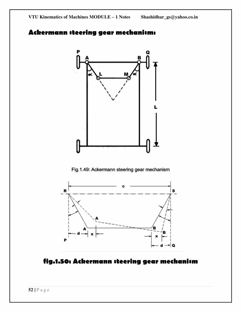
Ackermann steering gear mechanism:
Fig.1.49: Ackermann steering gear mechanism
fig.1.50: Ackermann steering gear mechanism

VTU Kinematics of Machines MODULE – 1 Notes [email protected]
53 | P a g e
Ackerman steering mechanism, RSAB is a four bar chain as shown in fig.1.50. Links RA and SB which are equal in length are integral with the stub axles. These links are connected with each other through track rod AB. When the vehicle is in straight ahead position, links RA and SB make equal angles α with the center line of the vehicle. The dotted lines in fig.1.50 indicate the position of the mechanism when the vehicle is turning left.
Let AB=1, RA=SB=r; ̂ = ̂ = � and in the turned
position, A ̂ ′ = � & B ̂ ′ =∅. IE, the stub axles of inner and
outer wheels turn by θ and φ angles respectively.
Neglecting the obliquity of the track rod in the turned position,
the movements of A and B in the horizontal direction may be
taken to be same (x).
Then, sin (α+θ) = �+
and sin (α-φ) = �−
Adding, sin (α+θ)+sin (α-φ) = � = 2sinα [1]
Angle α can be determined using the above equation. The
values of θ and φ to be taken in this equation are those found for correct steering using the equation
CotΦ-cotθ = � . [2]
This mechanism gives correct steering in only three positions. One, when θ = 0 and other two each corresponding to the turn

VTU Kinematics of Machines MODULE – 1 Notes [email protected]
54 | P a g e
to right or left (at a fixed turning angle, as determined by equation [1]).
The correct values of φ, [φc] corresponding to different values
of θ, for correct steering can be determined using equation [2].
For the given dimensions of the mechanism, actual values of φ,
[φa] can be obtained for different values of θ. The difference
between φc and φa will be very small for small angles of θ, but
the difference will be substantial, for larger values of θ. Such a difference will reduce the life of tyres because of greater wear on account of slipping.
But for larger values of θ, the automobile must take a sharp turn; hence is will be moving at a slow speed. At low speeds, wear of the tyres is less. Therefore, the greater difference between φc and φa larger values of θ ill not matter.
As this mechanism employs only turning pairs, friction and wear in the mechanism will be less. Hence its maintenance will be easier and is commonly employed in automobiles.

VTU Kinematics of Machines MODULE – 1 Notes [email protected]
55 | P a g e
IMPORTANT QUESTIONS:
1. Define the following: (VTU Feb 2006, July 2008, Jan 2009,
July 2009, Jan 2010, June 2010, Dec 2011, Dec 2012, July
2013, Jan 2014, July 2014, July 2015, Jan 2016, July 2016)
a. Link.
b. Kinematic chain.
c. Mechanism.
d. Structure.
e. Inversion.
f. Degree of Freedom.
g. Kinematic link.
h. Kinematic pair.
i. Kinematic mechanism.
j. Machine.
k. Higher pair.
l. Lower pair.
m. Mobility of mechanism.
n. Self closed pair.
o. Forced closed pair.
2. What do you mean by rigid link? Explain two types of
links with examples. (VTU Jan 2015)
3. Distinguish between:
a. Mechanism and Machine.
b. Structure and Kinematic chain.
c. Open pair and Closed pair.
d. Complete constraint and successful constraint.

VTU Kinematics of Machines MODULE – 1 Notes [email protected]
56 | P a g e
4. Describe with neat figures two inversions of double slider-
crank chain. (VTU July 2016)
5. With neat sketch, explain crank and slotted lever quick
return mechanism. (VTU July 2016)
6. Explain the pantograph mechanism, with a neat sketch.
State its applications. (VTU July 2016)
7. Draw a line diagram and explain peaucellier’s straight line mechanism. (VTU July 2016)
8. Explain with a neat sketch, the double slider crank chain
mechanism and its inversions (any two inversions with
application). (VTU Jan 2016)
9. Sketch peaucellier’s mechanism, and prove that it can
trace a straight line. (VTU Jan 2016)
10. With a neat sketch, explain the condition for
Ackermann’s mechanism. (VTU Jan 2016)
11. Define inversion of a kinematic chain. With the help of a
neat sketch explain inversions of single slider crank chain.
(VTU July 2016)
12. With the help of a neat sketch, explain the working
principle of crank and slotted lever mechanism. (VTU July
2015)
13. List various straight line generating mechanisms. With the
help of a neat sketch along with proof, explain how a
peaucellier mechanism generates a straight line. (VTU July
2015)
14. Explain the following inversions with neat sketch:
i) Double rocker mechanism.

VTU Kinematics of Machines MODULE – 1 Notes [email protected]
57 | P a g e
15. Crank and slotted lever type quick return motion
mechanism. (VTU Jan 2015)
16. Define degrees of freedom and state the relation for
the same for planar mechanisms having only turning and
sliding pairs. (VTU Jan 2015)
17. Sketch peaucellier’s mechanism and prove that it can
trace a straight line. (VTU Jan 2015)
18. Explain pawl and ratchet wheel mechanism with neat
sketch. (VTU Jan 2015)
19. With neat sketch, explain the conditions for correct
steering for Ackermann-mechanism. (VTU Jan 2015)
20. Sketch and explain the working of an elliptical
trammel. Prove that it traces an ellipse. (VTU July 2014)
21. Explain with a neat sketch. Crank and slotted lever quick
return motion mechanism. (VTU July 2014)
22. Explain with a neat sketch. Pantograph mechanism.
State its applications. (VTU July 2014)
23. Explain with a neat sketch, Geneva mechanism.
(VTU July 2014)
24. Describe with neat sketch two inversion of double
slider – crank chain mechanism. (VTU Jan 2014)
25. Derive an expression for necessary condition of
correct steering and explain Ackermann steering gear
with neat sketch. (VTU Jan 2014)
26. Explain with the help of neat sketches, the following
mechanisms: (VTU Jan 2008, Jan 2009, July 2009, Jan
2010, June 2010, Dec 2010, July 2011, June 2012, Dec 2012,
July 2013)

VTU Kinematics of Machines MODULE – 1 Notes [email protected]
58 | P a g e
i) Single slider crank mechanism.
ii) Intermittent motion mechanism.
iii) Two inversions of double slider-crank chain.
iv) parallel crank mechanism.
v) Quick return mechanism.
vi) Gnome engine mechanism.
vii) Four bar mechanism.
viii) Elliptical trammel.
ix) Peaucellier’s straight line mechanism.
x) Crank and slotted lever quick return motion
mechanism.
xi) Scotch yoke mechanism.
xii) Pantograph.
xiii) Hooke’s joint xiv) Toggle mechanism.
xv) Roberts mechanism.
xvi) Whitworth quick return motion mechanism.
xvii) Ratchet and pawl mechanism.
xviii) Geneva wheel mechanism.
27. With the help of neat sketch, explain the working
principle of Crank and slotted lever mechanism. (VTU July
2013)
28. Derive the condition for the correct steering
mechanism. For a four wheeled vehicle. (VTU July 2013)