Embed Size (px)
Citation preview
A COMPUTERIZED APPROACH FOR TOLERANCE ANALYSIS OF DISK CAMMECHANISMS WITH A FLAT-FACED FOLLOWER
Wen-Tung Chang1,* and Long-Iong Wu2
1Opto-Mechatronics Technology Center, National Taiwan University of Science and Technology,
Taipei 10607, Taiwan2
Department of Power Mechanical Engineering, National Tsing Hua University, Hsinchu 30013, Taiwan
* Corresponding author. E-mail: [email protected]
Received May 2009, Accepted September 2009
No. 09-CSME-27, E.I.C. Accession 3113
ABSTRACT
A computerized approach for analyzing the tolerances in disk cam mechanisms with a flat-faced follower is presented in this paper. Based on the simulated higher-pair contact analysis,the kinematic deviation of the follower motion caused by the tolerance amount of each designparameter can be determined numerically. The method is validated by means of analyzing thecase of an eccentric circular cam mechanism; such a case has an exact solution of the followermotion error. Compared with the exact solutions, the presented computerized approach isdemonstrated to be able to provide excellent accuracy and sufficient efficiency no matter howlarge the level of the tolerance is. Then, both the offset translating oblique flat-faced followerand the oscillating flat-faced follower cases are given to illustrate the presented method. Thepresented computerized approach and the obtained results can be helpful for toleranceallocation tasks of disk cam mechanisms with a flat-faced follower.
Keywords: Disk cam mechanism; Flat-faced follower; Tolerance analysis; Simulated higher-pair contact analysis; Mechanical error analysis; Poppet valve.
UNE APPROCHE INFORMATIQUE POUR L’ANALYSE DES TOLERANCES DEMECANISMES A CAME DISQUE AVEC GALET SUIVEUR PLAT
RESUME
L’article presente une approche informatique pour l’analyse des tolerances de mecanismes acame disque avec galet suiveur plat. En se basant sur l’analyse simulee du contact couple-eleve,la deviation cinematique du mouvement du suiveur, causee par l’amplitude de la tolerance dechacun des parametres, peut etre determinee numeriquement. La methode est verifiee au moyend’une analyse de cas de mecanisme de came disque circulaire excentrique; un tel cas presente unesolution exacte d’erreur de mouvement du suiveur. En comparant avec ces solutions exactes,dans l’approche informatique presentee, nous demontrons sa capacite de procurer uneexcellente precision et suffisamment d’efficacite peu importe le niveau de tolerance. Les cas degalet suiveur plat a decalage de translation oblique et de galet suiveur oscillant sont presentespour illustrer la methode. L’approche informatique et les resultats obtenus peuvent etre utilespour l’allocation de tolerance du mecanisme a came disque avec galet suiveur plat.
Mots-cles: Mecanisme a came disque; Galet suiveur plat; Analyse de tolerance; Analyse simuleedu contact couple-eleve; Analyse d’erreur mecanique; Soupape champignon.
Transactions of the Canadian Society for Mechanical Engineering, Vol. 33, No. 3, 2009 459
1. INTRODUCTION
The cam mechanism, basically consisting of a frame, a cam and a follower, provides a simpleand reliable means of controlling valve timing and lift in automobile engines. The cam usuallyrotates continuously to drive the follower by direct contact (i.e. higher-pair contact) forgenerating prescribed follower motion program with respect to the cam rotation angle (or time).Since the cam mechanism is a direct-contact mechanism, in high-speed machinery, even slightdeviations in cam contour may still produce excessive noise, wear and vibrations [1–3]. Tomaintain high quality and performance, strict control of tolerance amounts in a cam mechanismis necessary, although this induces high manufacturing and assembly costs at the same time.Therefore, a compromise simultaneously considering tolerance, cost and operating performanceis quite essential for cam designers and manufacturers.
In order to achieve reasonably acceptable performance of cam mechanisms, sufficientaccuracy of the cam contour and consequent close tolerances must be considered in the designphase. From the viewpoint of design for manufacturing and assembly (DFMA) [4,5], thetolerance of the cam profile and that of each design parameter should be specified at the largest(or optimal) values to make the components in a cam mechanism be fabricated easily. Thespecified tolerance combination should also meet the operating or functional considerations ofthe follower output. To this end, theoretical correlation between tolerance level of each designparameter and the follower motion deviation must be established. Such a mechanism toleranceanalysis [6], also known as the mechanical error analysis [7,8], which involves mathematicalmodeling and computerized computation, is one of the fundamental tools of optimal tolerancedesign for cam mechanisms. Through the tolerance analysis, expensive and time-consumingexperiments for deciding the optimal tolerance amounts in a cam mechanism could besuperseded.
A variety of analytical approaches have been introduced for the tolerance analysis of varioustypes of cam mechanisms [9–19]. Rao and Gavane [9], as well as Rao [10], considered thetolerances of cam profile and other design parameters as random variables, and then employeda stochastic approach for evaluating the actual kinematic and dynamic response of the followeroutput. Chiu et al. [11] applied the principle of the offset curve of a plane curve to perform theinfluence analysis of manufacturing and assembly errors of disk cam mechanisms. Zhang andWang [12] adopted the sensitivity analysis to derive output error equations of a disk cam withan offset translating roller follower while the error was assumed to be caused by the tolerance ofthe cam profile and those of other design parameters. Cheng [13] also adopted the sensitivityanalysis to derive output error equations of a globoidal cam mechanism for further performingits optimal tolerance synthesis. Valentini [14] used the sensitivity analysis to assess the influenceof mechanical errors in spatial cam mechanisms that are used in vehicle robotized gearboxes.Wu and Chang [15–17], employing the concept of equivalent linkage, proposed an analyticalmethod for analyzing mechanical errors in disk cams with either a roller follower or a flat-facedfollower. Chang et al. [18,19] then used the equivalent linkage method [15–17] to perform theconjugate condition analysis of assembled conjugate disk cams with measuring fixtures. Theseapproaches can provide a valuable source of idea for this analysis. Nevertheless, most of themare based on the sensitivity analysis and Taylor series and may lose accuracy when considering alarge level of manufacturing and assembly tolerances (or errors) exists in a cam mechanism [17].Litvin [20,21] developed a computerized methodology termed tooth contact analysis (TCA),based on the higher-pair contact simulation and the theory of gearing, for numericallydetermining contact conditions and kinematic errors of gear mechanisms. Such a simulated
Transactions of the Canadian Society for Mechanical Engineering, Vol. 33, No. 3, 2009 460
higher-pair contact analysis has been widely applied to evaluate the effects of manufacturingand assembly errors on various types of direct-contact mechanisms [22–25]. The advantage ofthis computerized methodology is that it can maintain sufficient accuracy no matter how largethe level of the tolerances is. By adopting the concept of simulated higher-pair contact analysis,Chang and Wu [26] have developed a computerized approach for analyzing tolerances in diskcam mechanisms with a roller follower. The developed computerized approach, as well as theTCA, is in essence a numerical approach, rather than an analytical approach, to simulatefollower motion errors caused by tolerances in the design parameters. Numerical iterationschemes are involved in the simulation. Because it deals with much computation, computersmust be applied as necessary analyzing tools. However, as compared to roller followers, flat-faced followers could be a simpler and more inexpensive choice for industrial applications. Forthis reason, most automobile engines nowadays use poppet valves, which are spring loadedclosed and pushed open by overhead cams with a flat-faced follower attached to the valve stem[27]. Therefore, it is necessary to further develop a computerized approach for analyzing thetolerances in disk cam mechanisms with a flat-faced follower.
This paper, still adopting the concept of simulated higher-pair contact [26], demonstrates asystematically numerical approach for analyzing tolerances in disk cam mechanisms with a flat-faced follower. With the aid of the parametric expressions of the cam profile and consideringvariable radial profile errors, the equations of tangency [20,21,26] especially for disk cams witheither a translating or an oscillating flat-faced follower are derived. In order to verify theaccuracy and efficiency of the presented method, an eccentric circular cam mechanism that hasan exact solution of the follower motion error is analyzed for comparison. Then, both the offsettranslating oblique flat-faced follower and the oscillating flat-faced follower cases are given toillustrate the presented method. In these illustrated cases, quantitative analysis and comparisonof tolerance effects on translating and oscillating flat-faced follower cases are performed. Thepresented numerical approach as well as the quantitative analyzing results may help camdesigners and manufacturers in properly allocating tolerances in disk cam mechanisms with aflat-faced follower.
2. PARAMETRIC EXPRESSIONS FOR THE CAM PROFILE
In order to undertake the tolerance analysis of disk cam mechanisms with a flat-facedfollower, the analytical expressions for the theoretical cam profile should be derived first. Theprofile of a disk cam can be determined through the concept of velocity instant centers [15–17,28–30]. For quick review and easy reference, the analytical approach for determining diskcam profiles parametrically in terms of the cam rotation angle is provided below [15–17,28,30].Here, disk cams with either an offset translating oblique flat-faced follower or an oscillatingflat-faced follower are demonstrated.
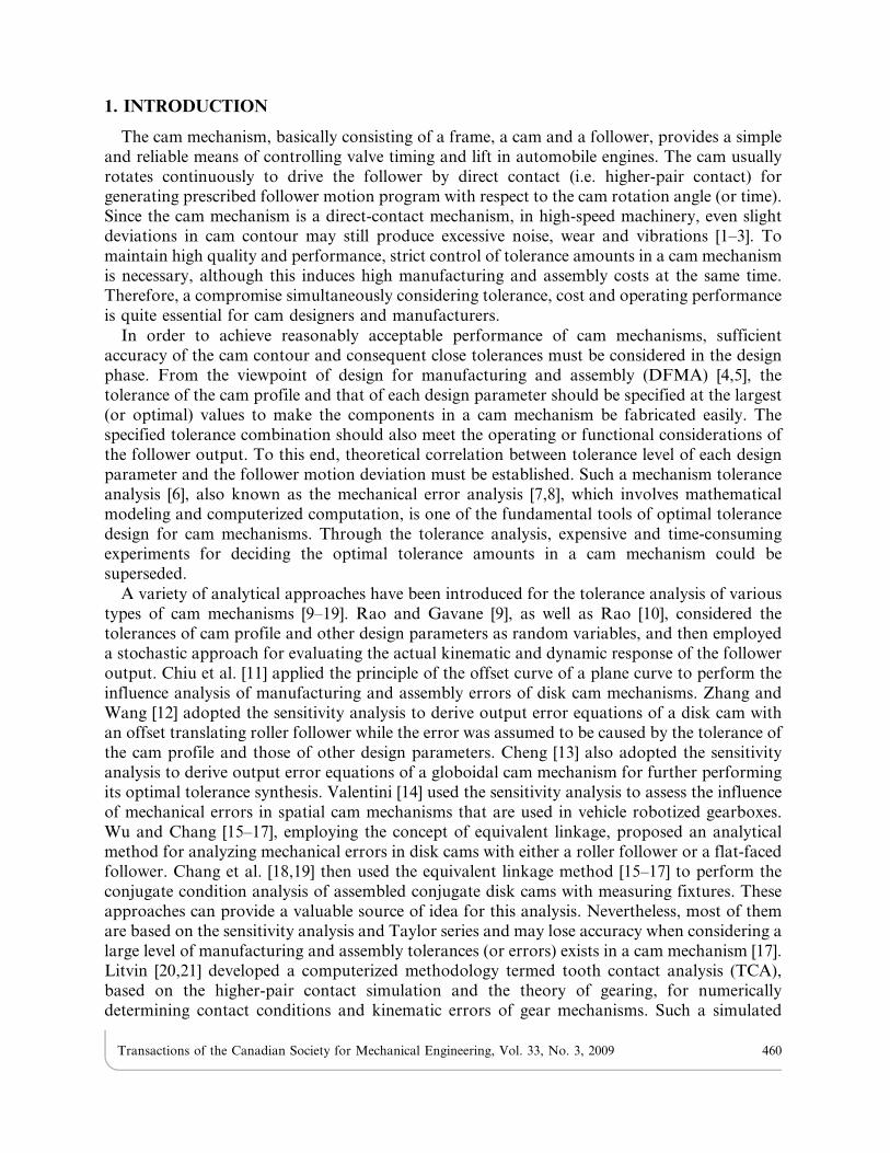
2.1. Disk Cam with an Offset Translating Oblique Flat-Faced FollowerFigure 1 shows a disk cam mechanism with an offset translating oblique flat-faced follower,
which is a general form for actuating poppet valves of engines. By setting up a Cartesiancoordinate system X-Y fixed on the cam and with its origin at the fixed pivot O2, the cam profilecoordinates may be expressed in terms of the cam rotation angle h, which is measured againstthe direction of cam rotation from the reference radial to cam center parallel to followertranslation. The cam is to rotate clockwise with a constant angular velocity of v2 rad/s. Forsimplicity, in the following, the frame will be consistently numbered as 1, the cam as 2 and the
Transactions of the Canadian Society for Mechanical Engineering, Vol. 33, No. 3, 2009 461
follower as 3. By labeling instant center I23 as Q and O2Q 5 q, where ‘I’ denotes the instantcenter and subscripts indicate the related links, the parametric vector equations of thetheoretical cam profile coordinates are [16,17]
RT (h)~RTx(h)
RTy(h)
� �~O2A~O2QzQA~
QA cos (hzw){q sin hQA sin (hzw)zq cos h
� �(1)
where
q~dL(h)
dh(2)
QA~L(h) cos w{(q{e) sin w (3)
in which, w is the oblique angle of the follower (i.e. the invariant pressure angle), e is the offsetand L(h) is the linear displacement function of the reference point P of the translating follower:
L(h)~rb sec w{e tan wzS(h) (4)
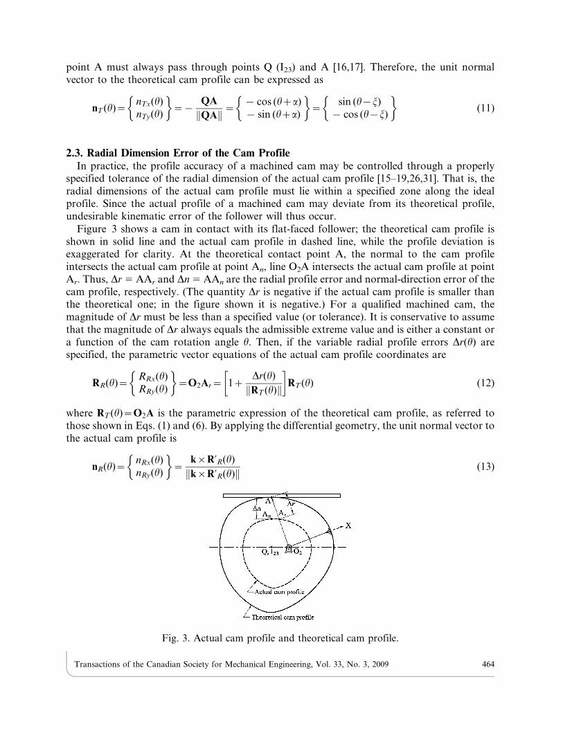
where rb is the radius of the base circle and S(h) is the linear motion program of the follower;S(h) is also known as the cam displacement function [1,2]. (The quantity w is positive if thefollower face is counterclockwise oblique from the horizontal; in the position shown it ispositive. Also, since the cam is to rotate clockwise, the quantity e is negative if the offset is to theright; in the position shown it is positive.) The common normal at the contact point A mustalways pass through points Q (I23) and A [16,17]. Therefore, the unit normal vector to thetheoretical cam profile can be expressed as
nT (h)~nTx(h)
nTy(h)
� �~{
QA
QAk k~{ cos (hzw)
{ sin (hzw)
� �(5)
Fig. 1. Disk cam with an offset translating oblique flat-faced follower.
Transactions of the Canadian Society for Mechanical Engineering, Vol. 33, No. 3, 2009 462
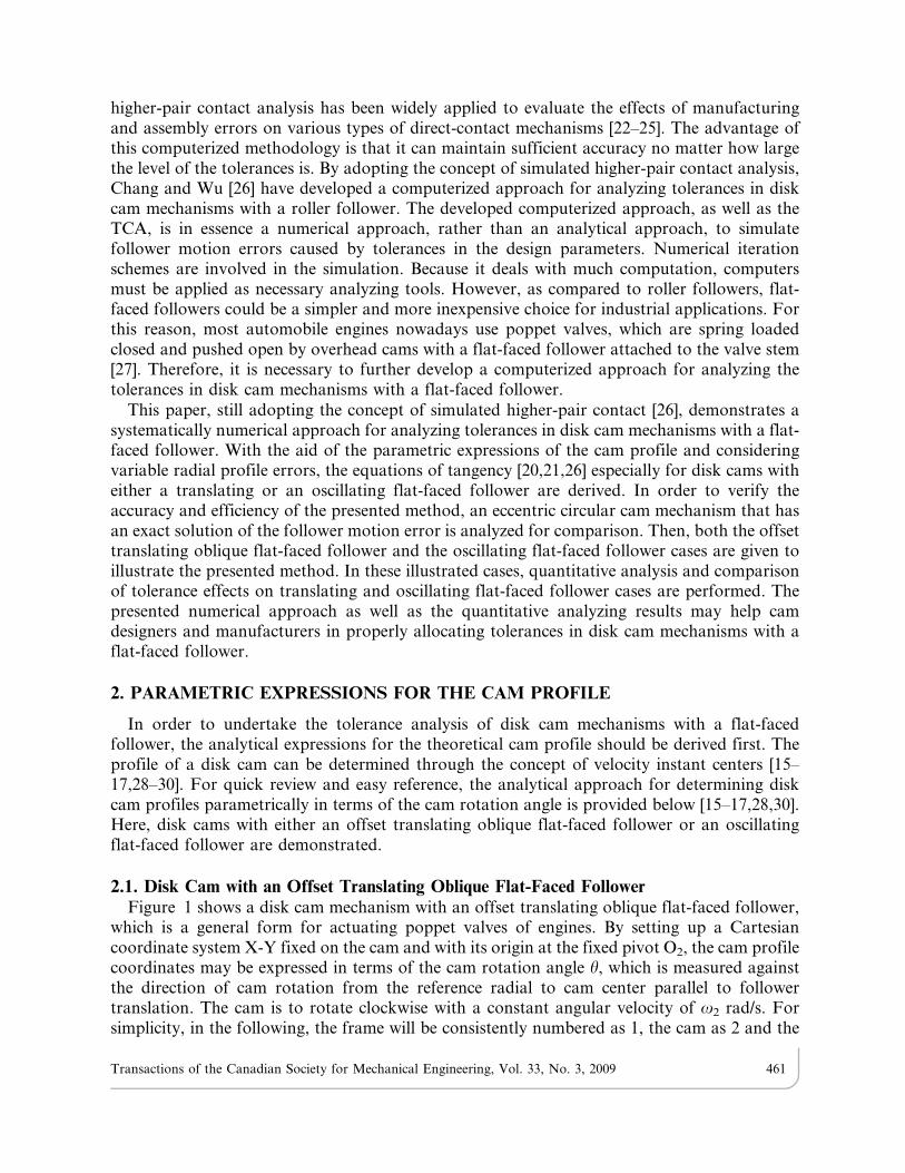
2.2. Disk Cam with an Oscillating Flat-Faced FollowerFigure 2 shows a disk cam mechanism with an oscillating flat-faced follower. In this case, f
represents the distance from the cam center O2 to the follower pivot point O3 (which is also thereference point of the oscillating follower) and e represents the follower face offset from thefollower pivot point. (If the follower face is offset from the pivot point towards the cam center,it is negative. The quantity e is positive in Fig. 2.) By setting up a Cartesian coordinate systemX-Y fixed on the cam and with its origin at the fixed pivot O2, the cam profile coordinates maybe expressed in terms of h. By labeling instant center I23 as Q and O2Q 5 q, the parametricvector equations of the theoretical cam profile coordinates are [16,17,28]
RT (h)~RTx(h)
RTy(h)
� �~O2A~O2QzQA~
(QEze) cos (hza){q cos h(QEze) sin (hza){q sin h
� �(6)
where
q~f
dj(h)
dh
1{dj(h)
dh
(7)
QE~(f zq) sin j(h) (8)
a~900{j(h) (9)
in which, j(h) is the angular displacement function of the follower:
j(h)~ sin{1 rb{e
f
� �zS(h) (10)
where, rb is the radius of the base circle and S(h) is the angular motion program of the follower;S(h) is also known as the cam displacement function [1,2]. The common normal at the contact
Fig. 2. Disk cam with an oscillating flat-faced follower.
Transactions of the Canadian Society for Mechanical Engineering, Vol. 33, No. 3, 2009 463
point A must always pass through points Q (I23) and A [16,17]. Therefore, the unit normalvector to the theoretical cam profile can be expressed as
nT (h)~nTx(h)
nTy(h)
� �~{
QA
QAk k~{ cos (hza)
{ sin (hza)
� �~
sin (h{j)
{ cos (h{j)
� �(11)
2.3. Radial Dimension Error of the Cam ProfileIn practice, the profile accuracy of a machined cam may be controlled through a properly
specified tolerance of the radial dimension of the actual cam profile [15–19,26,31]. That is, theradial dimensions of the actual cam profile must lie within a specified zone along the idealprofile. Since the actual profile of a machined cam may deviate from its theoretical profile,undesirable kinematic error of the follower will thus occur.
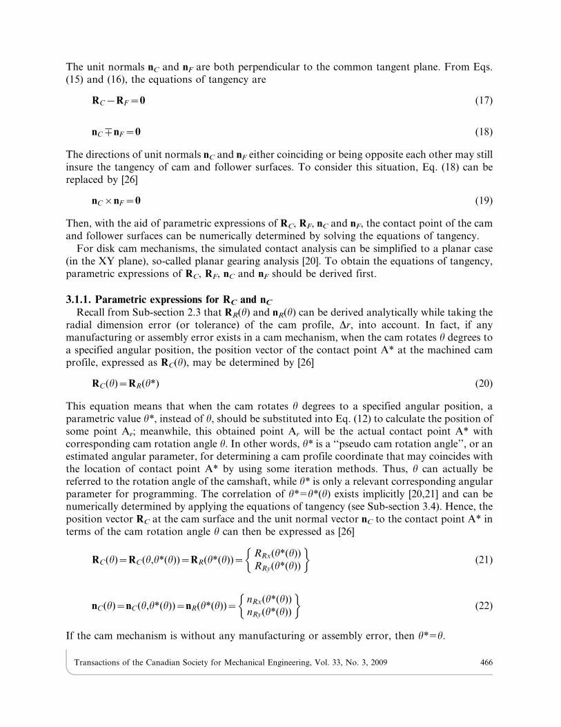
Figure 3 shows a cam in contact with its flat-faced follower; the theoretical cam profile isshown in solid line and the actual cam profile in dashed line, while the profile deviation isexaggerated for clarity. At the theoretical contact point A, the normal to the cam profileintersects the actual cam profile at point An, line O2A intersects the actual cam profile at pointAr. Thus, Dr 5 AAr and Dn 5 AAn are the radial profile error and normal-direction error of thecam profile, respectively. (The quantity Dr is negative if the actual cam profile is smaller thanthe theoretical one; in the figure shown it is negative.) For a qualified machined cam, themagnitude of Dr must be less than a specified value (or tolerance). It is conservative to assumethat the magnitude of Dr always equals the admissible extreme value and is either a constant ora function of the cam rotation angle h. Then, if the variable radial profile errors Dr(h) arespecified, the parametric vector equations of the actual cam profile coordinates are
RR(h)~RRx(h)
RRy(h)
� �~O2Ar~ 1z
Dr(h)
RT (h)k k
� �RT (h) (12)
where RT (h)~O2A is the parametric expression of the theoretical cam profile, as referred tothose shown in Eqs. (1) and (6). By applying the differential geometry, the unit normal vector tothe actual cam profile is
nR(h)~nRx(h)
nRy(h)
� �~
k|R’R(h)
k|R’R(h)k k (13)
Fig. 3. Actual cam profile and theoretical cam profile.
Transactions of the Canadian Society for Mechanical Engineering, Vol. 33, No. 3, 2009 464

where k is the unit vector of the Z-axis (the axis of cam rotation), and
R’R(h)~dRR(h)
dh~ 1z
Dr(h)
RT (h)k k
� �R’T (h)z
Dr’(h)
RT (h)k k{½RT (h).R’T (h)�Dr(h)
RT (h)k k3
( )RT (h) (14)
where R’T (h)~dRT (h)=dh is the tangent vector to the theoretical cam profile and Dr’(h)~d½Dr(h)�=dh is the differentiation of the radial profile error. Because the analytical expressions ofR’T (h) and Dr’(h) may be complex, a numerical algorithm to compute them can be utilized.
3. SIMULATED HIGHER-PAIR CONTACT AND TOLERANCE ANALYSIS
The simulated higher-pair contact analysis is to simulate the meshing and contact of two rigidbody surfaces with localized point contact at every instant [20,21]. It can also provide a valuablesource of idea for analyzing the tolerance in disk cam mechanisms with a flat-faced follower.
3.1. Fundamentals of the Simulated Higher-Pair Contact AnalysisFigure 4 shows tangency of mating 3-D cam and follower surfaces, in which a Cartesian
coordinate system X-Y-Z is fixed on the cam, with its origin at the fixed point O2; O2Z is theaxis of cam rotation. The position vectors RC and RF indicate cam and follower surfaces,respectively, represented in coordinate system O2-XYZ; nC and nF express surface unit normalsof cam and follower, respectively, represented in coordinate system O2-XYZ. In order to be incontinuous tangency, the position vectors of cam and follower surfaces must coincide at pointA* and their unit normals must be collinear [20,21]. Here, the actual contact point A* may notcoincide with the theoretical contact point A (not shown in the figure) when manufacturing andassembly errors are involved. Then, the necessary and sufficient conditions for the existence ofpoint A* are
RC~RF~O2A1 (15)
nC~+nF (16)
Fig. 4. Tangency of mating 3-D cam and follower surfaces.
Transactions of the Canadian Society for Mechanical Engineering, Vol. 33, No. 3, 2009 465
The unit normals nC and nF are both perpendicular to the common tangent plane. From Eqs.(15) and (16), the equations of tangency are
RC{RF~0 (17)
nC+nF~0 (18)
The directions of unit normals nC and nF either coinciding or being opposite each other may stillinsure the tangency of cam and follower surfaces. To consider this situation, Eq. (18) can bereplaced by [26]
nC|nF~0 (19)
Then, with the aid of parametric expressions of RC, RF, nC and nF, the contact point of the camand follower surfaces can be numerically determined by solving the equations of tangency.
For disk cam mechanisms, the simulated contact analysis can be simplified to a planar case(in the XY plane), so-called planar gearing analysis [20]. To obtain the equations of tangency,parametric expressions of RC, RF, nC and nF should be derived first.
3.1.1. Parametric expressions for RC and nC
Recall from Sub-section 2.3 that RR(h) and nR(h) can be derived analytically while taking theradial dimension error (or tolerance) of the cam profile, Dr, into account. In fact, if anymanufacturing or assembly error exists in a cam mechanism, when the cam rotates h degrees toa specified angular position, the position vector of the contact point A* at the machined camprofile, expressed as RC(h), may be determined by [26]
RC(h)~RR(h1) (20)
This equation means that when the cam rotates h degrees to a specified angular position, aparametric value h*, instead of h, should be substituted into Eq. (12) to calculate the position ofsome point Ar; meanwhile, this obtained point Ar will be the actual contact point A* withcorresponding cam rotation angle h. In other words, h* is a ‘‘pseudo cam rotation angle’’, or anestimated angular parameter, for determining a cam profile coordinate that may coincides withthe location of contact point A* by using some iteration methods. Thus, h can actually bereferred to the rotation angle of the camshaft, while h* is only a relevant corresponding angularparameter for programming. The correlation of h*5h*(h) exists implicitly [20,21] and can benumerically determined by applying the equations of tangency (see Sub-section 3.4). Hence, theposition vector RC at the cam surface and the unit normal vector nC to the contact point A* interms of the cam rotation angle h can then be expressed as [26]
RC(h)~RC(h,h1(h))~RR(h1(h))~RRx(h1(h))
RRy(h1(h))
� �(21)
nC(h)~nC(h,h1(h))~nR(h1(h))~nRx(h1(h))
nRy(h1(h))
� �(22)
If the cam mechanism is without any manufacturing or assembly error, then h*5h.
Transactions of the Canadian Society for Mechanical Engineering, Vol. 33, No. 3, 2009 466
3.1.2. Parametric expressions for RF and nF
To derive RF and nF, the locus of the follower profile, a straight line, relative to the Cartesiancoordinate system fixed on the cam should be determined first. To this end, two additionalparameters y* and u* are required. The parameter y*, being the actual follower displacement,represents the actual linear displacement L* or angular displacement j* for translating oroscillating followers, respectively. The parameter u* is a length parameter paralleling thefollower face to aid the calculation of the distance between the actual contact point A* and thereference point of the follower. After the position of the reference point and the orientation ofthe follower have been determined by using the actual follower displacement y* and otherknown design parameters, the coordinates of any point of the follower contour (a straight line)can be further described by the length parameter u* with vector loop equations. When takingthe known tolerance amount in each design parameter of the cam mechanism into account, theparameters y* and u* are functions of the cam rotation angle h and can be solved numerically(see Sub-section 3.4). Hence, the position vector RF at the follower surface and the unit normalnF to the contact point A* in terms of the cam rotation angle h can then be expressed as
RF (h)~RF (h,y1(h),u1(h))~RFx(h,y1(h),u1(h))
RFy(h,y1(h),u1(h))
� �(23)
nF (h)~nF (h,y1(h),u1(h))~nFx(h,y1(h),u1(h))
nFy(h,y1(h),u1(h))
� �(24)
3.1.3. Equations of tangencySubstituting Eqs. (21), (22), (23) and (24) into Eqs. (17) and (19) yields the equations of
tangency for disk cam mechanisms with a flat-faced follower:
F1~RCx(h,h1(h)){RFx(h,y1(h),u1(h))~0 (25)
F2~RCy(h,h1(h)){RFy(h,y1(h),u1(h))~0 (26)
F3~nCx(h,h1(h))nFy(h,y1(h),u1(h)){nCy(h,h1(h))nFx(h,y1(h),u1(h))~0 (27)
Let h be the input variable, the three nonlinear equations can be solved by numerical schemes,such as Newton-Raphson method, to obtain functions h*(h), y*(h) and u*(h). Then, thedisplacement error of the follower will be
DS(h)~y1(h){y(h) (28)
where y(h) is the theoretical displacement function of the follower.
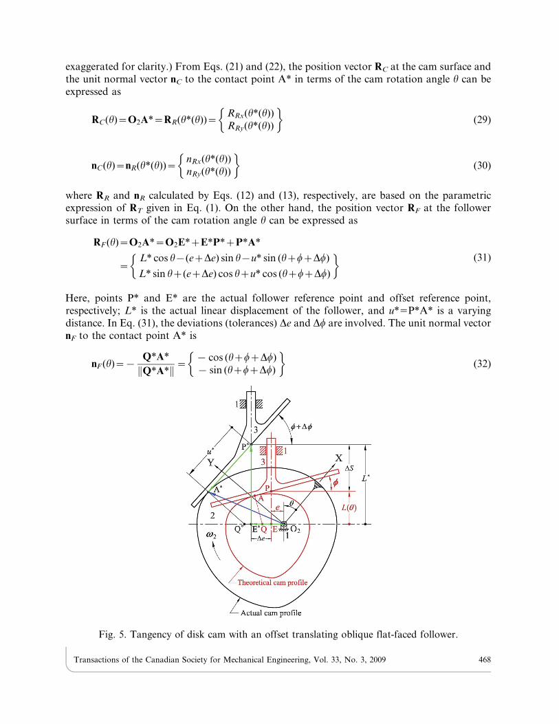
3.2. Application to Disk Cam with an Offset Translating Oblique Flat-Faced FollowerFigure 5 shows the tangency of a disk cam with an offset translating oblique flat-faced
follower, where, because of the radial dimensional error of the cam profile Dr, the variation ofthe follower offset De and the oblique angle error Dw, the instant contact point varies from pointA to point A* with corresponding cam rotation angle h. (Here, the deviations Dr, De and Dw are
Transactions of the Canadian Society for Mechanical Engineering, Vol. 33, No. 3, 2009 467
exaggerated for clarity.) From Eqs. (21) and (22), the position vector RC at the cam surface andthe unit normal vector nC to the contact point A* in terms of the cam rotation angle h can beexpressed as
RC(h)~O2A1~RR(h1(h))~RRx(h1(h))
RRy(h1(h))
� �(29)
nC(h)~nR(h1(h))~nRx(h1(h))
nRy(h1(h))
� �(30)
where RR and nR calculated by Eqs. (12) and (13), respectively, are based on the parametricexpression of RT given in Eq. (1). On the other hand, the position vector RF at the followersurface in terms of the cam rotation angle h can be expressed as
RF (h)~O2A1~O2E1zE1P1zP1A1
~L1 cos h{(ezDe) sin h{u1 sin (hzwzDw)
L1 sin hz(ezDe) cos hzu1 cos (hzwzDw)
� �(31)
Here, points P* and E* are the actual follower reference point and offset reference point,respectively; L* is the actual linear displacement of the follower, and u*5P*A* is a varyingdistance. In Eq. (31), the deviations (tolerances) De and Dw are involved. The unit normal vectornF to the contact point A* is
nF (h)~{Q1A1Q1A1k k~
{ cos (hzwzDw)
{ sin (hzwzDw)
� �(32)
Fig. 5. Tangency of disk cam with an offset translating oblique flat-faced follower.
Transactions of the Canadian Society for Mechanical Engineering, Vol. 33, No. 3, 2009 468
where point Q* is the actual instant center I23. From Eq. (31), it can be seen that L1:y1 in thiscase. The distance u*5P*A* is the length parameter to determine the position vector of pointA* at the follower profile. Substituting Eqs. (29), (30), (31) and (32) into Eqs. (25), (26) and (27)gives three simultaneous nonlinear equations in three unknowns h*, L* and u*. For eachspecified value of h, these three equations can be solved numerically, and the lineardisplacement error of the follower will be
DS(h)~L1(h){L(h) (33)
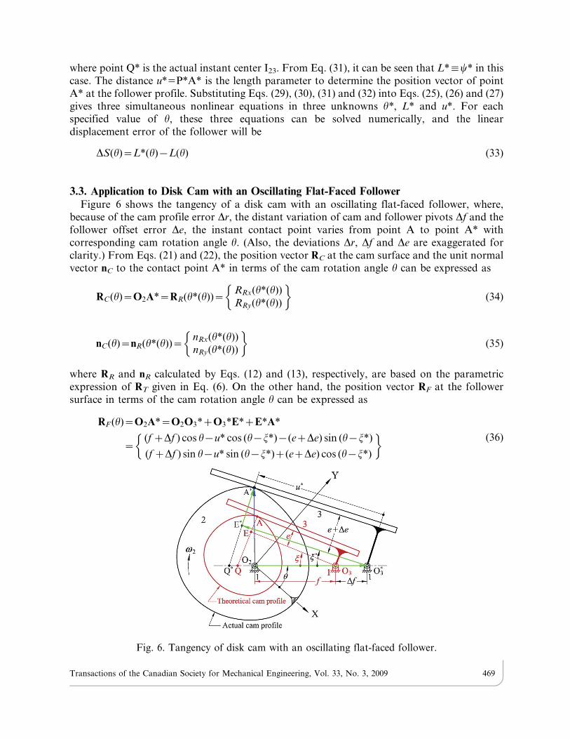
3.3. Application to Disk Cam with an Oscillating Flat-Faced FollowerFigure 6 shows the tangency of a disk cam with an oscillating flat-faced follower, where,
because of the cam profile error Dr, the distant variation of cam and follower pivots Df and thefollower offset error De, the instant contact point varies from point A to point A* withcorresponding cam rotation angle h. (Also, the deviations Dr, Df and De are exaggerated forclarity.) From Eqs. (21) and (22), the position vector RC at the cam surface and the unit normalvector nC to the contact point A* in terms of the cam rotation angle h can be expressed as
RC(h)~O2A1~RR(h1(h))~RRx(h1(h))
RRy(h1(h))
� �(34)
nC(h)~nR(h1(h))~nRx(h1(h))
nRy(h1(h))
� �(35)
where RR and nR calculated by Eqs. (12) and (13), respectively, are based on the parametricexpression of RT given in Eq. (6). On the other hand, the position vector RF at the followersurface in terms of the cam rotation angle h can be expressed as
RF (h)~O2A1~O2O31zO31E1zE1A1
~(f zDf ) cos h{u1 cos (h{j1){(ezDe) sin (h{j1)
(f zDf ) sin h{u1 sin (h{j1)z(ezDe) cos (h{j1)
� �(36)
Fig. 6. Tangency of disk cam with an oscillating flat-faced follower.
Transactions of the Canadian Society for Mechanical Engineering, Vol. 33, No. 3, 2009 469
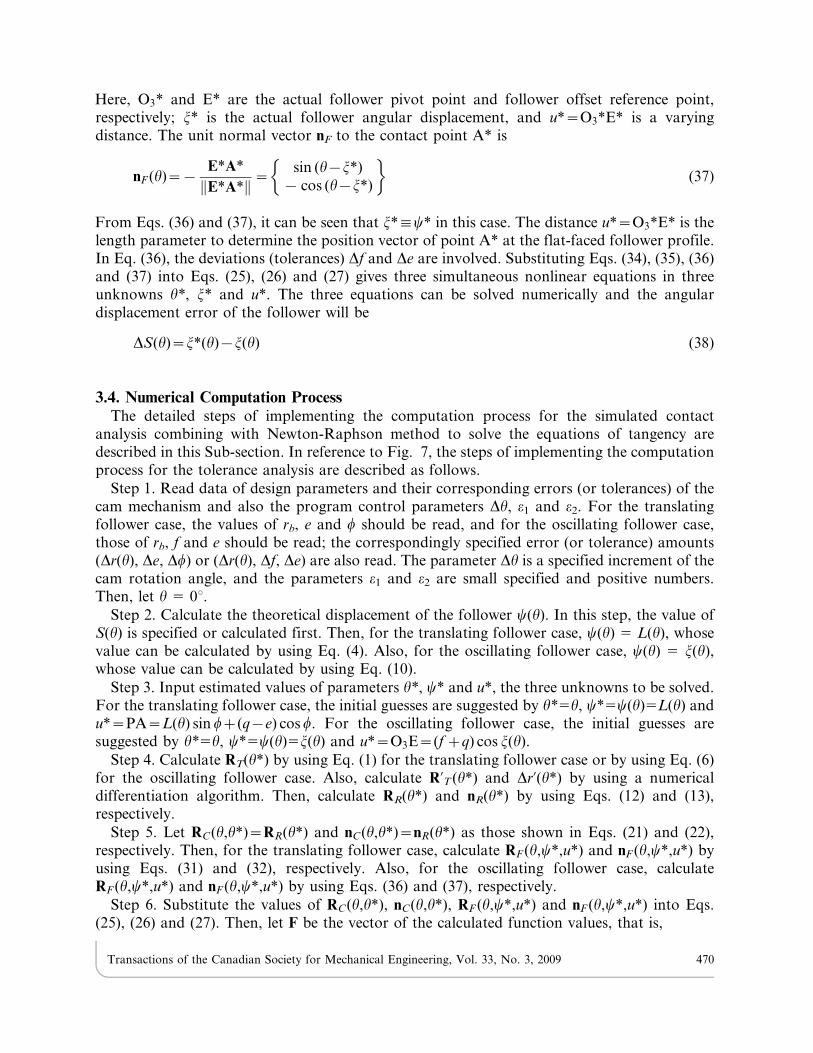
Here, O31 and E* are the actual follower pivot point and follower offset reference point,respectively; j* is the actual follower angular displacement, and u1~O31E1 is a varyingdistance. The unit normal vector nF to the contact point A* is
nF (h)~{E1A1E1A1k k~
sin (h{j1)
{ cos (h{j1)
� �(37)
From Eqs. (36) and (37), it can be seen that j1:y1 in this case. The distance u1~O31E1 is thelength parameter to determine the position vector of point A* at the flat-faced follower profile.In Eq. (36), the deviations (tolerances) Df and De are involved. Substituting Eqs. (34), (35), (36)and (37) into Eqs. (25), (26) and (27) gives three simultaneous nonlinear equations in threeunknowns h*, j* and u*. The three equations can be solved numerically and the angulardisplacement error of the follower will be
DS(h)~j1(h){j(h) (38)
3.4. Numerical Computation ProcessThe detailed steps of implementing the computation process for the simulated contact
analysis combining with Newton-Raphson method to solve the equations of tangency aredescribed in this Sub-section. In reference to Fig. 7, the steps of implementing the computationprocess for the tolerance analysis are described as follows.
Step 1. Read data of design parameters and their corresponding errors (or tolerances) of thecam mechanism and also the program control parameters Dh, e1 and e2. For the translatingfollower case, the values of rb, e and w should be read, and for the oscillating follower case,those of rb, f and e should be read; the correspondingly specified error (or tolerance) amounts(Dr(h), De, Dw) or (Dr(h), Df, De) are also read. The parameter Dh is a specified increment of thecam rotation angle, and the parameters e1 and e2 are small specified and positive numbers.Then, let h 5 0u.
Step 2. Calculate the theoretical displacement of the follower y(h). In this step, the value ofS(h) is specified or calculated first. Then, for the translating follower case, y(h) 5 L(h), whosevalue can be calculated by using Eq. (4). Also, for the oscillating follower case, y(h) 5 j(h),whose value can be calculated by using Eq. (10).
Step 3. Input estimated values of parameters h*, y* and u*, the three unknowns to be solved.For the translating follower case, the initial guesses are suggested by h*5h, y*5y(h)5L(h) andu1~PA~L(h) sin wz(q{e) cos w. For the oscillating follower case, the initial guesses aresuggested by h*5h, y*5y(h)5j(h) and u1~O3E~(f zq) cos j(h).
Step 4. Calculate RT(h*) by using Eq. (1) for the translating follower case or by using Eq. (6)for the oscillating follower case. Also, calculate R’T (h1) and Dr’(h1) by using a numericaldifferentiation algorithm. Then, calculate RR(h*) and nR(h*) by using Eqs. (12) and (13),respectively.
Step 5. Let RC(h,h1)~RR(h1) and nC(h,h1)~nR(h1) as those shown in Eqs. (21) and (22),respectively. Then, for the translating follower case, calculate RF (h,y1,u1) and nF (h,y1,u1) byusing Eqs. (31) and (32), respectively. Also, for the oscillating follower case, calculateRF (h,y1,u1) and nF (h,y1,u1) by using Eqs. (36) and (37), respectively.
Step 6. Substitute the values of RC(h,h1), nC(h,h1), RF (h,y1,u1) and nF (h,y1,u1) into Eqs.(25), (26) and (27). Then, let F be the vector of the calculated function values, that is,
Transactions of the Canadian Society for Mechanical Engineering, Vol. 33, No. 3, 2009 470
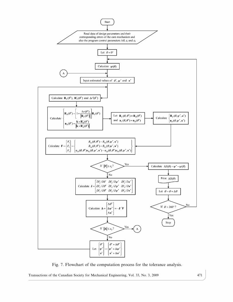
Fig. 7. Flowchart of the computation process for the tolerance analysis.
Transactions of the Canadian Society for Mechanical Engineering, Vol. 33, No. 3, 2009 471
F~
F1
F2
F3
8<:
9=;~
RCx(h,h1){RFx(h,y1,u1)
RCy(h,h1){RFy(h,y1,u1)
nCx(h,h1)nFy(h,y1,u1){nCy(h,h1)nFx(h,y1,u1)
8<:
9=; (39)
Check whether Fk kƒe1 or not. If so, go to Step 7, or else, go to Step 8.
Step 7. Calculate the displacement error of the follower DS(h) by using Eq. (33) for thetranslating follower case or by using Eq. (38) for the oscillating follower case. Then, print DS(h)and update the cam rotation angle by h 5 h+Dh. Check whether h . 360u or not. If so, stop thecomputation process. Else, go to Step 2.
Step 8. Calculate the Jacobian matrix of vector F by
J~
LF1=Lh1 LF1=Ly1 LF1=Lu1LF2=Lh1 LF2=Ly1 LF2=Lu1LF3=Lh1 LF3=Ly1 LF3=Lu1
24
35 (40)
in which, employing a numerical differentiation algorithm for calculating the partial differentialterms is suggested.
Step 9. Calculate the vector of updating values for the unknowns by
D~
Dh1Dy1Du1
8<:
9=;~{J{1F (41)
Check whether Dk kƒe2 or not. If so, go to Step 3 for inputting new estimated values ofparameters h*, y* and u*. Else, update the parameters by
h1y1u1
8<:
9=;~
h1zDh1y1zDy1u1zDu1
8<:
9=; (42)
and then go to Step 4.
The above steps demonstrate the use of Newton-Raphson method to solve the equations oftangency, and also to determine functions h*(h), y*(h) and u*(h) numerically. After the actualfollower displacement function y*(h) is determined, the follower displacement error functionDS(h) can be correspondingly obtained. After the computation process being programmed, thefollower motion deviations caused by different tolerance degrees can all be simulated.
4. VALIDITY OF THE METHOD
The validity of the presented method may be recognized through analyzing the cammechanism shown in Fig. 8, an eccentric circular cam with an offset translating oblique flat-faced follower. The cam mechanism has a circular cam profile and whose equivalent linkage isan invariant Scotch yoke mechanism. Thus, an exact solution of the follower motion error isavailable. A Cartesian coordinate system X-Y is fixed on the cam with the Y-axis passingthrough point K, the center of curvature of the circular cam. The linear displacement functionof the reference point P can be expressed as
L(h)~re sin hzR cos wz(re cos hzR sin w{e) tan w (43)
Transactions of the Canadian Society for Mechanical Engineering, Vol. 33, No. 3, 2009 472
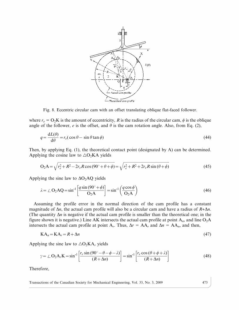
where re 5 O2K is the amount of eccentricity, R is the radius of the circular cam, w is the obliqueangle of the follower, e is the offset, and h is the cam rotation angle. Also, from Eq. (2),
q~dL(h)
dh~re( cos h{ sin h tan w) (44)
Then, by applying Eq. (1), the theoretical contact point (designated by A) can be determined.Applying the cosine law to gO2KA yields
O2A~
ffiffiffiffiffiffiffiffiffiffiffiffiffiffiffiffiffiffiffiffiffiffiffiffiffiffiffiffiffiffiffiffiffiffiffiffiffiffiffiffiffiffiffiffiffiffiffiffiffiffiffiffiffiffiffiffiffiffiffiffiffir2
ezR2{2reR cos (900zhzw)q
~
ffiffiffiffiffiffiffiffiffiffiffiffiffiffiffiffiffiffiffiffiffiffiffiffiffiffiffiffiffiffiffiffiffiffiffiffiffiffiffiffiffiffiffiffiffiffiffiffiffir2
ezR2z2reR sin (hzw)q
(45)
Applying the sine law to DO2AQ yields
l~%O2AQ~sin-1 q sin (900zw)
O2A
� �~sin-1 q cos w
O2A
� �(46)
Assuming the profile error in the normal direction of the cam profile has a constantmagnitude of Dn, the actual cam profile will also be a circular cam and have a radius of R+Dn.(The quantity Dn is negative if the actual cam profile is smaller than the theoretical one; in thefigure shown it is negative.) Line AK intersects the actual cam profile at point An, and line O2Aintersects the actual cam profile at point Ar. Thus, Dr 5 AAr and Dn 5 AAn, and then,
KAn~KAr~RzDn (47)
Applying the sine law to gO2KAr yields
c~%O2ArK~sin-1 re sin (900{h{w{l)
(RzDn)
� �~sin-1 re cos (hzwzl)
(RzDn)
� �(48)
Therefore,
Fig. 8. Eccentric circular cam with an offset translating oblique flat-faced follower.
Transactions of the Canadian Society for Mechanical Engineering, Vol. 33, No. 3, 2009 473

O2Ar~
ffiffiffiffiffiffiffiffiffiffiffiffiffiffiffiffiffiffiffiffiffiffiffiffiffiffiffiffiffiffiffiffiffiffiffiffiffiffiffiffiffiffiffiffiffiffiffiffiffiffiffiffiffiffiffiffiffiffiffiffiffiffiffiffiffiffiffiffiffiffiffiffiffiffiffiffiffiffiffiffiffiffiffiffiffiffiffiffiffiffiffiffiffiffiffiffiffiffiffiffiffiffiffir2
ez(RzDn)2{2re(RzDn) cos (900{czhzwzl)
q~
ffiffiffiffiffiffiffiffiffiffiffiffiffiffiffiffiffiffiffiffiffiffiffiffiffiffiffiffiffiffiffiffiffiffiffiffiffiffiffiffiffiffiffiffiffiffiffiffiffiffiffiffiffiffiffiffiffiffiffiffiffiffiffiffiffiffiffiffiffiffiffiffiffiffiffiffiffiffiffiffiffiffiffiffiffiffiffiffiffiffir2
ez(RzDn)2{2re(RzDn) sin (c{h{w{l)
q (49)
From Eqs. (45) and (49), the radial profile error can be expressed as
Dr(h)~AAr~O2Ar{O2A
~
ffiffiffiffiffiffiffiffiffiffiffiffiffiffiffiffiffiffiffiffiffiffiffiffiffiffiffiffiffiffiffiffiffiffiffiffiffiffiffiffiffiffiffiffiffiffiffiffiffiffiffiffiffiffiffiffiffiffiffiffiffiffiffiffiffiffiffiffiffiffiffiffiffiffiffiffiffiffiffiffiffiffiffiffiffiffiffiffiffiffir2
ez(RzDn)2{2re(RzDn) sin (c{h{w{l)
q{
ffiffiffiffiffiffiffiffiffiffiffiffiffiffiffiffiffiffiffiffiffiffiffiffiffiffiffiffiffiffiffiffiffiffiffiffiffiffiffiffiffiffiffiffiffiffiffiffiffir2
ezR2z2reR sin (hzw)q (50)
This derived radial profile error function is substituted into Eq. (12) for calculating the actualcam profile coordinates in order to undertake the tolerance analysis by applying the presentedmethod. On the other hand, from equation (43), the exact solution of the follower motion errorcan be expressed as
DSex(h)~fre sin hz(RzDn) cos wz½re cos hz(RzDn) sin w{e� tan wg{½re sin hzR cos wz(re cos hzR sin w{e) tan w�~Dn( cos wz sin w tan w)~Dn sec w
(51)
From the final result of Eq. (51), it is found that the exact follower motion error has a constantmagnitude of Dn sec w in this case.
For comparison of the presented method and the exact solution, a set of design parametersare given by re 5 60 mm, R 5 100 mm, w 5 15u, and e 5 15 mm. The constant normal-directionerror of the circular cam profile is specified as Dn 5 22 mm (a corresponding tolerance of IT6)or Dn 5 870 mm (a corresponding tolerance of IT14) for the computation. The computationprocess shown in Sub-section 3.4 is employed for determining function DSr(h) caused by Dr(h),in which, MATLAB is used for the programming, and the program control parameters aregiven by Dh 5 0.1u and e1 5 e2 5 161028. Figure 9 shows the normalized radial profile error(Dr/Dn) with respect to the cam rotation angle h. For Dn 5 22 mm, the translating follower hasan exact displacement error of DSex(h)~22| sec 150~22:776076 mm, and the numericaldifference between DSr(h) and DSex(h) is shown in Fig. 10(a). As can be seen, the difference(DSr – DSex) ranges between 28.72610211 mm and 9.04610211 mm and has a root-mean-square value of 2.58610211 mm. Likewise, for Dn 5 870 mm, the translating follower has anexact displacement error of DSex(h)~870| sec 150~900:690277 mm, and the numericaldifference between DSr(h) and DSex(h) is shown in Fig. 10(b). It is found that the difference(DSr – DSex) ranges between 27.73610211 mm and 8.61610211 mm and has a root-mean-square value of 2.47610211 mm. From the computing results, it is verified that the numericaldifferences between the presented method and the exact solutions can be almost ignored nomatter how large the tolerance grade is.
In addition, to test the efficiency of the presented method, the CPU time for computing thefollower motion errors was recorded and evaluated. The hardware environment of thecomputation was given as follows: a personal computer with the Intel Core 2 Duo E8400processor whose core speed is 3.0 GHz. For the program control parameters being given by Dh5 0.1u and e1 5 e2 5 161028, the average CPU time for executing 100 times of the computationprogram was 13.76 seconds. That is, the displacement error calculation for each of the 3600specified cam angles took merely 0.0038 second in average.
Transactions of the Canadian Society for Mechanical Engineering, Vol. 33, No. 3, 2009 474
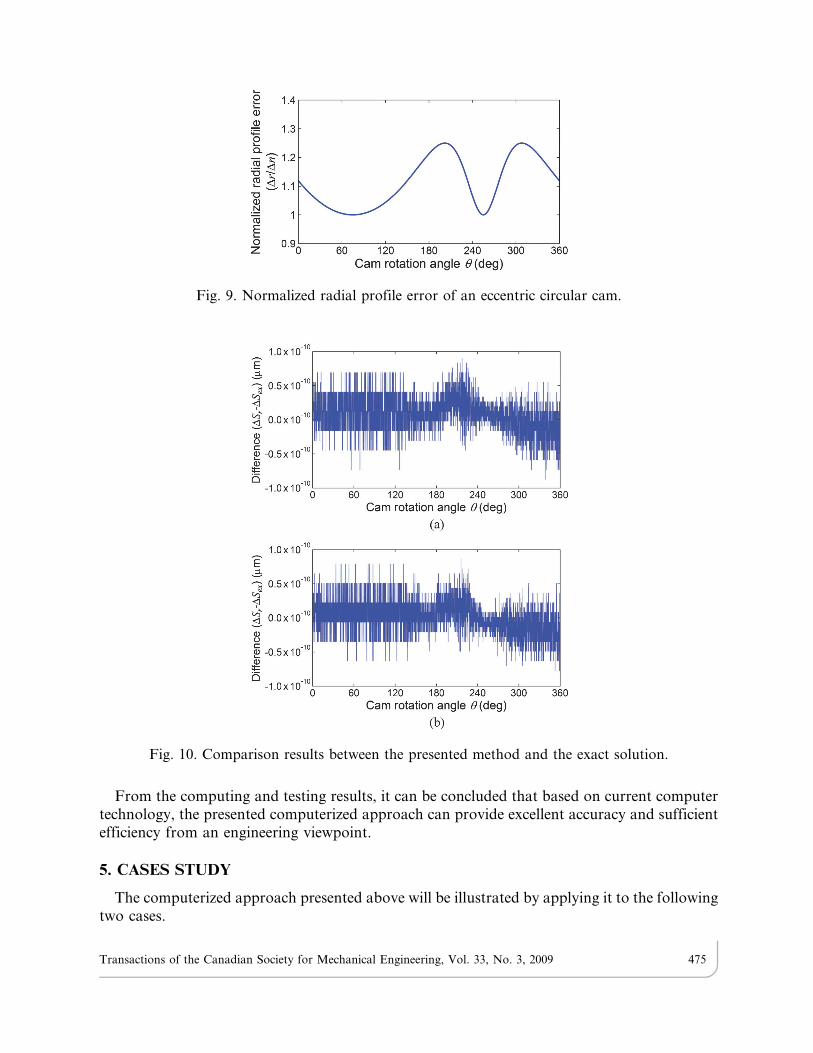
From the computing and testing results, it can be concluded that based on current computertechnology, the presented computerized approach can provide excellent accuracy and sufficientefficiency from an engineering viewpoint.
5. CASES STUDY
The computerized approach presented above will be illustrated by applying it to the followingtwo cases.
Fig. 9. Normalized radial profile error of an eccentric circular cam.
Fig. 10. Comparison results between the presented method and the exact solution.
Transactions of the Canadian Society for Mechanical Engineering, Vol. 33, No. 3, 2009 475
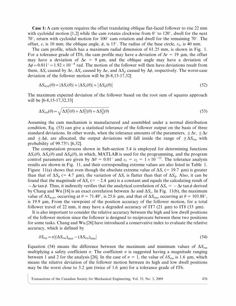
Case 1: A cam system requires the offset translating oblique flat-faced follower to rise 22 mmwith cycloidal motion [1,2] while the cam rotates clockwise from 0u to 120u, dwell for the next70u, return with cycloidal motion for 100u cam rotation and dwell for the remaining 70u. Theoffset, e, is 10 mm; the oblique angle, w, is 15u. The radius of the base circle, rb, is 40 mm.
The cam profile, which has a maximum radial dimension of 61.25 mm, is shown in Fig. 1.For a tolerance grade of IT6, the cam profile may have a deviation of Dr 5 19 mm, the offsetmay have a deviation of De 5 9 mm, and the oblique angle may have a deviation ofDw~0:0110~1:92|10{4 rad. The motion of the follower will then have deviations result fromthem, DSr caused by Dr, DSe caused by De, and DSw caused by Dw, respectively. The worst-casedeviation of the follower motion will be [6-8,15-17,32]
DSwor(h)~ DSr(h)j jz DSe(h)j jz DSw(h)�� �� (52)
The maximum expected deviation of the follower based on the root sum of squares approachwill be [6-8,15-17,32,33]
DSrss(h)~ffiffiffiffiffiffiffiffiffiffiffiffiffiffiffiffiffiffiffiffiffiffiffiffiffiffiffiffiffiffiffiffiffiffiffiffiffiffiffiffiffiffiffiffiffiffiffiffiffiffiffiDS2
r (h)zDS2e (h)zDS2
w(h)q
(53)
Assuming the cam mechanism is manufactured and assembled under a normal distributioncondition, Eq. (53) can give a statistical tolerance of the follower output on the basis of threestandard deviations. In other words, when the tolerance amounts of the parameters, ¡Dr, ¡De
and ¡Dw, are allocated, the output deviations will fall inside the range of ¡DSrss withprobability of 99.73% [6,32].
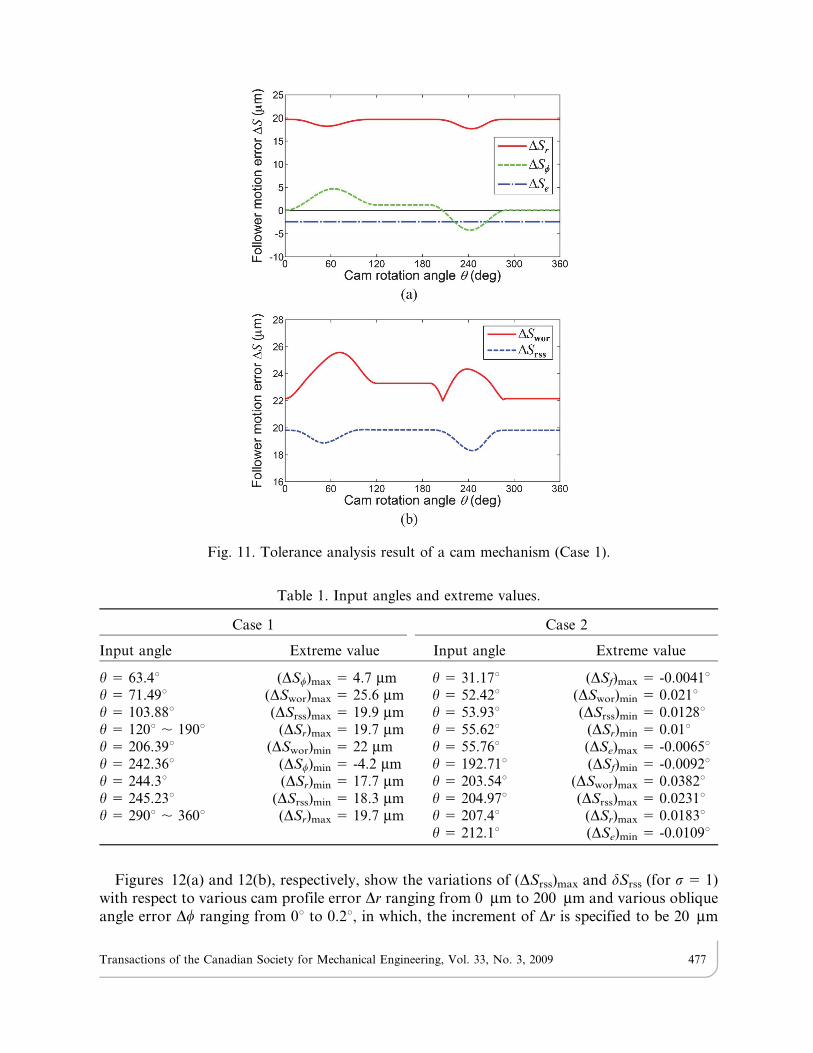
The computation process shown in Sub-section 3.4 is employed for determining functionsDSr(h), DSe(h) and DSw(h), in which, MATLAB is used for the programming, and the programcontrol parameters are given by Dh 5 0.01u and e1 5 e2 5 1610212. The tolerance analysisresults are shown in Fig. 11, and their corresponding extreme values are also listed in Table 1.Figure 11(a) shows that even though the absolute extreme value of DSr (5 19.7 mm) is greaterthan that of DSw (5 4.7 mm), the variation of DSr is flatter than that of DSw. Also, it can befound that the magnitude of DSe (5 22.4 mm) is a constant and equals the calculating result of{De tan w. Thus, it indirectly verifies that the analytical correlation of DSe 5 {De tan w derivedby Chang and Wu [16] is an exact correlation between De and DSe. In Fig. 11(b), the maximumvalue of DSwor, occurring at h 5 71.49u, is 25.6 mm, and that of DSrss, occurring at h 5 103.88u,is 19.9 mm, From the viewpoint of the position accuracy of the follower motion, for a totalfollower travel of 22 mm, it may have a degraded accuracy of IT7 (21 mm) to IT8 (33 mm).
It is also important to consider the relative accuracy between the high and low dwell positionsof the follower motion since the follower is designed to reciprocate between these two positionsfor some tasks. Chang and Wu [26] have introduced a conservative index to evaluate the relativeaccuracy, which is defined by
dSrss~s½(DSrss)max{(DSrss)min� (54)
Equation (54) means the difference between the maximum and minimum values of DSrss
multiplying a safety coefficient s. The coefficient s is suggested having a magnitude rangingbetween 1 and 2 for the analysis [26]. In the case of s 5 1, the value of dSrss is 1.6 mm, whichmeans the relative deviation of the follower motion between its high and low dwell positionsmay be the worst close to 3.2 mm (twice of 1.6 mm) for a tolerance grade of IT6.
Transactions of the Canadian Society for Mechanical Engineering, Vol. 33, No. 3, 2009 476
Figures 12(a) and 12(b), respectively, show the variations of (DSrss)max and dSrss (for s 5 1)with respect to various cam profile error Dr ranging from 0 mm to 200 mm and various obliqueangle error Dw ranging from 0u to 0.2u, in which, the increment of Dr is specified to be 20 mm
Fig. 11. Tolerance analysis result of a cam mechanism (Case 1).
Table 1. Input angles and extreme values.
Case 1 Case 2
Input angle Extreme value Input angle Extreme value
h 5 63.4u (DSw)max 5 4.7 mm h 5 31.17u (DSf)max 5 -0.0041uh 5 71.49u (DSwor)max 5 25.6 mm h 5 52.42u (DSwor)min 5 0.021uh 5 103.88u (DSrss)max 5 19.9 mm h 5 53.93u (DSrss)min 5 0.0128uh 5 120u , 190u (DSr)max 5 19.7 mm h 5 55.62u (DSr)min 5 0.01uh 5 206.39u (DSwor)min 5 22 mm h 5 55.76u (DSe)max 5 -0.0065uh 5 242.36u (DSw)min 5 -4.2 mm h 5 192.71u (DSf)min 5 -0.0092uh 5 244.3u (DSr)min 5 17.7 mm h 5 203.54u (DSwor)max 5 0.0382uh 5 245.23u (DSrss)min 5 18.3 mm h 5 204.97u (DSrss)max 5 0.0231uh 5 290u , 360u (DSr)max 5 19.7 mm h 5 207.4u (DSr)max 5 0.0183u
h 5 212.1u (DSe)min 5 -0.0109u
Transactions of the Canadian Society for Mechanical Engineering, Vol. 33, No. 3, 2009 477
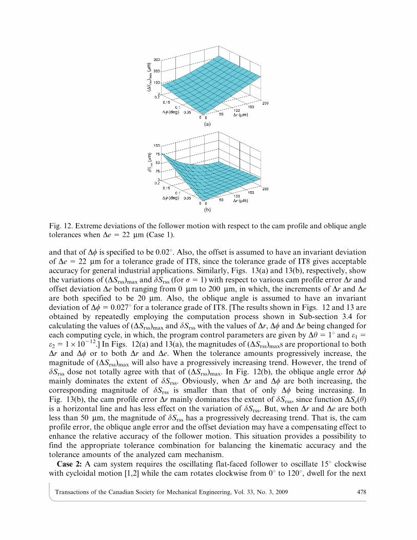
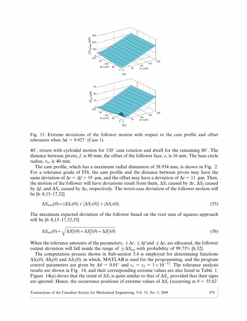
and that of Dw is specified to be 0.02u. Also, the offset is assumed to have an invariant deviationof De 5 22 mm for a tolerance grade of IT8, since the tolerance grade of IT8 gives acceptableaccuracy for general industrial applications. Similarly, Figs. 13(a) and 13(b), respectively, showthe variations of (DSrss)max and dSrss (for s 5 1) with respect to various cam profile error Dr andoffset deviation De both ranging from 0 mm to 200 mm, in which, the increments of Dr and Deare both specified to be 20 mm. Also, the oblique angle is assumed to have an invariantdeviation of Dw 5 0.027u for a tolerance grade of IT8. [The results shown in Figs. 12 and 13 areobtained by repeatedly employing the computation process shown in Sub-section 3.4 forcalculating the values of (DSrss)max and dSrss with the values of Dr, Dw and De being changed foreach computing cycle, in which, the program control parameters are given by Dh 5 1u and e1 5
e2 5 1610212.] In Figs. 12(a) and 13(a), the magnitudes of (DSrss)maxs are proportional to bothDr and Dw or to both Dr and De. When the tolerance amounts progressively increase, themagnitude of (DSrss)max will also have a progressively increasing trend. However, the trend ofdSrss dose not totally agree with that of (DSrss)max. In Fig. 12(b), the oblique angle error Dwmainly dominates the extent of dSrss. Obviously, when Dr and Dw are both increasing, thecorresponding magnitude of dSrss is smaller than that of only Dw being increasing. InFig. 13(b), the cam profile error Dr mainly dominates the extent of dSrss, since function DSe(h)is a horizontal line and has less effect on the variation of dSrss. But, when Dr and De are bothless than 50 mm, the magnitude of dSrss has a progressively decreasing trend. That is, the camprofile error, the oblique angle error and the offset deviation may have a compensating effect toenhance the relative accuracy of the follower motion. This situation provides a possibility tofind the appropriate tolerance combination for balancing the kinematic accuracy and thetolerance amounts of the analyzed cam mechanism.
Case 2: A cam system requires the oscillating flat-faced follower to oscillate 15u clockwisewith cycloidal motion [1,2] while the cam rotates clockwise from 0u to 120u, dwell for the next
Fig. 12. Extreme deviations of the follower motion with respect to the cam profile and oblique angletolerances when De 5 22 mm (Case 1).
Transactions of the Canadian Society for Mechanical Engineering, Vol. 33, No. 3, 2009 478
40u, return with cycloidal motion for 120u cam rotation and dwell for the remaining 80u. Thedistance between pivots, f, is 80 mm; the offset of the follower face, e, is 16 mm. The base circleradius, rb, is 40 mm.
The cam profile, which has a maximum radial dimension of 58.934 mm, is shown in Fig. 2.For a tolerance grade of IT6, the cam profile and the distance between pivots may have thesame deviation of Dr 5 Df 5 19 mm, and the offset may have a deviation of De 5 11 mm. Then,the motion of the follower will have deviations result from them, DSr caused by Dr, DSf causedby Df, and DSe caused by De, respectively. The worst-case deviation of the follower motion willbe [6–8,15–17,32]
DSwor(h)~ DSr(h)j jz DSf (h)�� ��z DSe(h)j j (55)
The maximum expected deviation of the follower based on the root sum of squares approachwill be [6–8,15–17,32,33]
DSrss(h)~ffiffiffiffiffiffiffiffiffiffiffiffiffiffiffiffiffiffiffiffiffiffiffiffiffiffiffiffiffiffiffiffiffiffiffiffiffiffiffiffiffiffiffiffiffiffiffiffiffiffiffiDS2
r (h)zDS2f (h)zDS2
e (h)q
(56)
When the tolerance amounts of the parameters, ¡Dr, ¡Df and ¡De, are allocated, the followeroutput deviation will fall inside the range of ¡DSrss with probability of 99.73% [6,32].
The computation process shown in Sub-section 3.4 is employed for determining functionsDSr(h), DSf(h) and DSe(h), in which, MATLAB is used for the programming, and the programcontrol parameters are given by Dh 5 0.01u and e1 5 e2 5 1610212. The tolerance analysisresults are shown in Fig. 14, and their corresponding extreme values are also listed in Table 1.Figure 14(a) shows that the trend of DSr is quite similar to that of DSe, provided that their signsare ignored. Hence, the occurrence positions of extreme values of DSr (occurring at h 5 55.62u
Fig. 13. Extreme deviations of the follower motion with respect to the cam profile and offsettolerances when Dw 5 0.027u (Case 1).
Transactions of the Canadian Society for Mechanical Engineering, Vol. 33, No. 3, 2009 479
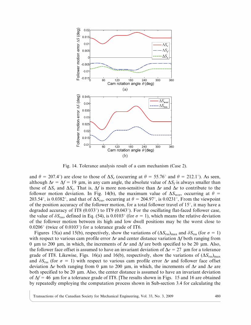
and h 5 207.4u) are close to those of DSe (occurring at h 5 55.76u and h 5 212.1u). As seen,although Dr 5 Df 5 19 mm, in any cam angle, the absolute value of DSf is always smaller thanthose of DSr and DSe. That is, Df is more non-sensitive than Dr and De to contribute to thefollower motion deviation. In Fig. 14(b), the maximum value of DSwor, occurring at h 5
203.54u, is 0.0382u, and that of DSrss, occurring at h 5 204.97u, is 0.0231u, From the viewpointof the position accuracy of the follower motion, for a total follower travel of 15u, it may have adegraded accuracy of IT8 (0.033u) to IT9 (0.043u). For the oscillating flat-faced follower case,the value of dSrss, defined in Eq. (54), is 0.0103u (for s 5 1), which means the relative deviationof the follower motion between its high and low dwell positions may be the worst close to0.0206u (twice of 0.0103u) for a tolerance grade of IT6.
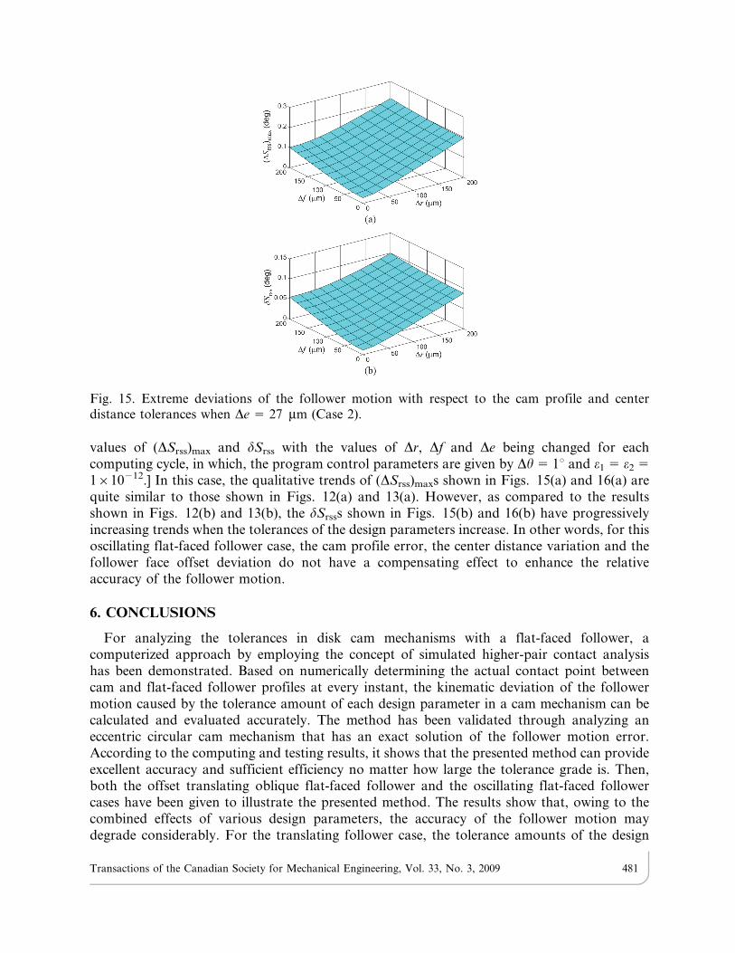
Figures 15(a) and 15(b), respectively, show the variations of (DSrss)max and dSrss (for s 5 1)with respect to various cam profile error Dr and center distance variation Df both ranging from0 mm to 200 mm, in which, the increments of Dr and Df are both specified to be 20 mm. Also,the follower face offset is assumed to have an invariant deviation of De 5 27 mm for a tolerancegrade of IT8. Likewise, Figs. 16(a) and 16(b), respectively, show the variations of (DSrss)max
and dSrss (for s 5 1) with respect to various cam profile error Dr and follower face offsetdeviation De both ranging from 0 mm to 200 mm, in which, the increments of Dr and De areboth specified to be 20 mm. Also, the center distance is assumed to have an invariant deviationof Df 5 46 mm for a tolerance grade of IT8. [The results shown in Figs. 15 and 16 are obtainedby repeatedly employing the computation process shown in Sub-section 3.4 for calculating the
Fig. 14. Tolerance analysis result of a cam mechanism (Case 2).
Transactions of the Canadian Society for Mechanical Engineering, Vol. 33, No. 3, 2009 480
values of (DSrss)max and dSrss with the values of Dr, Df and De being changed for eachcomputing cycle, in which, the program control parameters are given by Dh 5 1u and e1 5 e2 5
1610212.] In this case, the qualitative trends of (DSrss)maxs shown in Figs. 15(a) and 16(a) arequite similar to those shown in Figs. 12(a) and 13(a). However, as compared to the resultsshown in Figs. 12(b) and 13(b), the dSrsss shown in Figs. 15(b) and 16(b) have progressivelyincreasing trends when the tolerances of the design parameters increase. In other words, for thisoscillating flat-faced follower case, the cam profile error, the center distance variation and thefollower face offset deviation do not have a compensating effect to enhance the relativeaccuracy of the follower motion.
6. CONCLUSIONS
For analyzing the tolerances in disk cam mechanisms with a flat-faced follower, acomputerized approach by employing the concept of simulated higher-pair contact analysishas been demonstrated. Based on numerically determining the actual contact point betweencam and flat-faced follower profiles at every instant, the kinematic deviation of the followermotion caused by the tolerance amount of each design parameter in a cam mechanism can becalculated and evaluated accurately. The method has been validated through analyzing aneccentric circular cam mechanism that has an exact solution of the follower motion error.According to the computing and testing results, it shows that the presented method can provideexcellent accuracy and sufficient efficiency no matter how large the tolerance grade is. Then,both the offset translating oblique flat-faced follower and the oscillating flat-faced followercases have been given to illustrate the presented method. The results show that, owing to thecombined effects of various design parameters, the accuracy of the follower motion maydegrade considerably. For the translating follower case, the tolerance amounts of the design
Fig. 15. Extreme deviations of the follower motion with respect to the cam profile and centerdistance tolerances when De 5 27 mm (Case 2).
Transactions of the Canadian Society for Mechanical Engineering, Vol. 33, No. 3, 2009 481
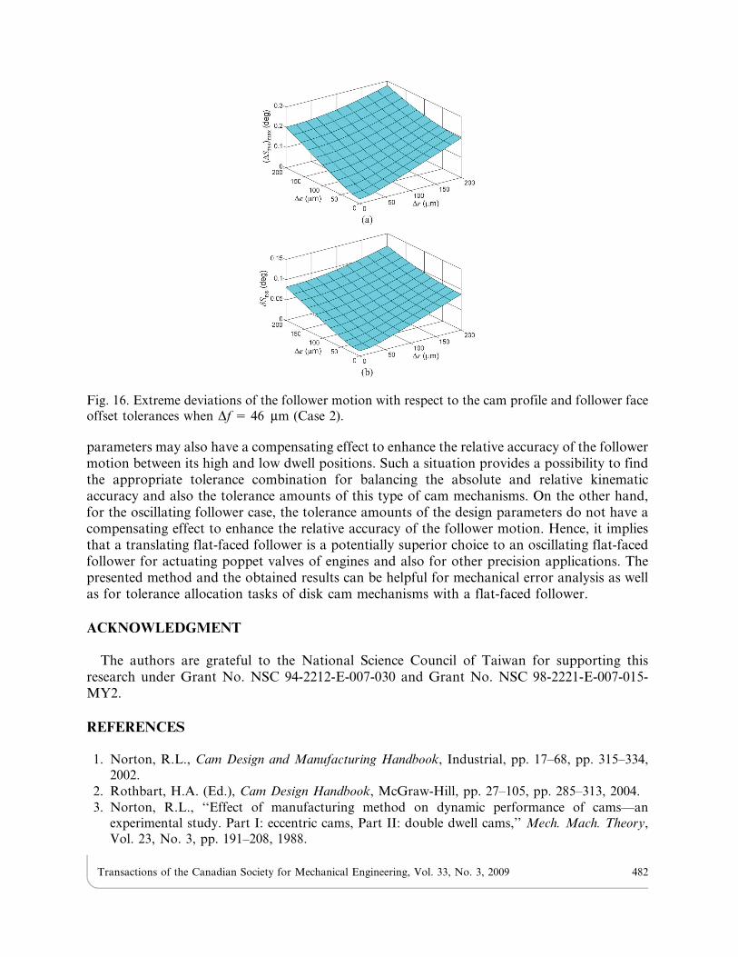
parameters may also have a compensating effect to enhance the relative accuracy of the followermotion between its high and low dwell positions. Such a situation provides a possibility to findthe appropriate tolerance combination for balancing the absolute and relative kinematicaccuracy and also the tolerance amounts of this type of cam mechanisms. On the other hand,for the oscillating follower case, the tolerance amounts of the design parameters do not have acompensating effect to enhance the relative accuracy of the follower motion. Hence, it impliesthat a translating flat-faced follower is a potentially superior choice to an oscillating flat-facedfollower for actuating poppet valves of engines and also for other precision applications. Thepresented method and the obtained results can be helpful for mechanical error analysis as wellas for tolerance allocation tasks of disk cam mechanisms with a flat-faced follower.
ACKNOWLEDGMENT
The authors are grateful to the National Science Council of Taiwan for supporting thisresearch under Grant No. NSC 94-2212-E-007-030 and Grant No. NSC 98-2221-E-007-015-MY2.
REFERENCES
1. Norton, R.L., Cam Design and Manufacturing Handbook, Industrial, pp. 17–68, pp. 315–334,2002.
2. Rothbart, H.A. (Ed.), Cam Design Handbook, McGraw-Hill, pp. 27–105, pp. 285–313, 2004.
3. Norton, R.L., ‘‘Effect of manufacturing method on dynamic performance of cams—anexperimental study. Part I: eccentric cams, Part II: double dwell cams,’’ Mech. Mach. Theory,Vol. 23, No. 3, pp. 191–208, 1988.
Fig. 16. Extreme deviations of the follower motion with respect to the cam profile and follower faceoffset tolerances when Df 5 46 mm (Case 2).
Transactions of the Canadian Society for Mechanical Engineering, Vol. 33, No. 3, 2009 482
4. Molloy, O., Tilley, S. and Warman, E.A., Design for Manufacturing and Assembly: Concepts,
Architectures and Implementation, Chapman & Hall, 1998.
5. Boothroyd, G., Dewhurst, P. and Knight, W., Product Design for Manufacture and Assembly,
2nd ed., Marcel Dekker, 2002.
6. Chase, K.W. and Parkinson, A.R., ‘‘A survey of research in the application of tolerance analysisto the design of mechanical assemblies,’’ Res. Eng. Design, Vol. 3, No. 1, pp. 23–38, 1991.
7. Hartenberg, R.S. and Denavit, J., Kinematic Synthesis of Linkages, McGraw-Hill, pp. 315–320,1964.
8. Grosjean, J., Kinematics and Dynamics of Mechanisms, McGraw-Hill, pp. 267–285, 1991.
9. Rao, S.S. and Gavane, S.S., ‘‘Analysis and synthesis of mechanical error in cam-followersystems,’’ Trans. ASME J. Mech. Des., Vol. 104, No. 1, pp. 52–62, 1982.
10. Rao, S.S., ‘‘Error analysis of cam-follower systems: a probabilistic approach,’’ Proc. Instn
Mech. Engrs, Part C: J. Mech. Eng. Sci., Vol. 198, No. 12, pp. 155–162, 1984.
11. Chiu, H., Ozaki, H., Sato, E., Suzuki, T., Oho, A. and Ariura, Y., ‘‘An analysis using offsetcurves for profiles, manufacturing and errors of plane cams,’’ JSME Int. J., Series C, Vol. 36,No. 1, pp. 110–118, 1993.
12. Zhang, C. and Wang, H.P., ‘‘Tolerance analysis and synthesis for cam mechanisms,’’ Int. J.
Prod. Res., Vol. 31, No. 5, pp. 1229–1245, 1993.
13. Cheng, H.Y., ‘‘Optimum tolerance synthesis for globoidal cam mechanisms,’’ JSME Int. J.,
Series C, Vol. 45, No. 2, pp. 519–526, 2002.
14. Valentini, P.P., ‘‘Tolerance allocation in spatial cam assembly for vehicle applications,’’ Int. J.
Veh. Syst. Model. Test., Vol. 3, No. 3, pp. 198–212, 2008.
15. Wu, L.I. and Chang, W.T., ‘‘Analysis of mechanical errors in disc cam mechanisms,’’ Proc.
Instn Mech. Engrs, Part C: J. Mech. Eng. Sci., Vol. 219, No. 2, pp. 209–224, 2005.
16. Chang, W.T. and Wu, L.I., ‘‘Mechanical error analysis of disk cam mechanisms with a flat-
faced follower,’’ J. Mech. Sci. Technol., Vol. 20, No. 3, pp. 345–357, 2006.
17. Chang, W.T., Analysis of Mechanical Errors in Planar Cam Mechanisms and Its Applications,Ph.D. Dissertation, Department of Power Mechanical Engineering, National Tsing Hua
University, Hsinchu, Taiwan, 2007.
18. Chang, W.T. and Wu, L.I., ‘‘A simplified method for examining profile deviations of conjugatedisk cams,’’ Trans. ASME, J. Mech. Des., Vol. 130, No. 5, 052601, 2008.
19. Chang, W.T., Wu, L.I. and Liu, C.H., ‘‘Inspecting profile deviations of conjugate disk cams bya rapid indirect method,’’ Mech. Mach. Theory, Vol. 44, No. 8, pp. 1580–1594, 2009.
20. Litvin, F.L., Theory of Gearing, NASA Reference Publication 1212, pp. 87–92, pp. 241–295, 1989.
21. Litvin, F.L., Gear Geometry and Applied Theory, Prentice Hall, pp. 258–287, 1994.
22. Tsay, C.B., ‘‘Helical gears with involute shaped teeth: geometry, computer simulation, toothcontact analysis, and stress analysis,’’ Trans. ASME J. Mech. Transm. Autom. Des., Vol. 110,No. 4, pp. 482–491, 1988.
23. Wang, W.H., Tseng, C.H. and Tsay, C.B., ‘‘Surface contact analysis for a spatial cammechanism,’’ Trans. ASME J. Mech. Des., Vol. 119, No. 2, pp. 169–177, 1997.
24. Tseng, J.T. and Tsay, C.B., ‘‘Undercutting and contact characteristics of cylindrical gears with
curvilinear shaped teeth generated by hobbing,’’ Trans. ASME J. Mech. Des., Vol. 128, No. 3,pp. 634–643, 2006.
25. Bruyere, J., Dantan, J.Y., Bigot, R. and Martin, P., ‘‘Statistical tolerance analysis of bevel gear
by tooth contact analysis and Monte Carlo simulation,’’ Mech. Mach. Theory, Vol. 42, No. 10,pp. 1326–1351, 2007.
26. Chang, W.T. and Wu, L.I., ‘‘Computerized tolerance analysis of disk cam mechanisms with a
roller follower,’’ Eng. Comput., Vol. 25, No. 3, pp. 247–260, 2009.
Transactions of the Canadian Society for Mechanical Engineering, Vol. 33, No. 3, 2009 483
27. Pulkrabek, W.W., Engineering Fundamentals of the Internal Combustion Engine, Prentice-Hall,p. 16, p. 24, 1997.
28. Wu, L.I., ‘‘Calculating conjugate cam profiles by vector equations,’’ Proc. Instn. Mech. Engrs,
Part C, J. Mech. Eng. Sci., Vol. 217, No. 10, pp. 1117–1123, 2003.
29. Wu, L.I., Chang, W.T. and Liu, C.H., ‘‘The design of varying velocity translating cammechanisms,’’ Mech. Mach. Theory, Vol. 42, No. 3, pp. 1326–1351, 2007.
30. Chang, W.T., Wu, L.I. and Liu, C.H., ‘‘The kinematic design of a planar-cam type pick-and-place device,’’ J. Mech. Sci. Technol, Vol. 22, No. 12, pp. 2328–2336, 2008.
31. Chang, W.T., Wu, L.I., Fuh, K.H. and Lin, C.C., ‘‘Inspecting profile errors of conjugatedisk cams with coordinate measurement,’’ Trans. ASME J. Manuf. Sci. Eng., Vol. 130, No. 1,011009, 2008.
32. Creveling, C.M., Tolerance Design: a Handbook for Developing Optimal Specifications, Addison-Wesley, pp. 124–148, 1997.
33. Garrett, R.E. and Hall Jr, A.S., ‘‘Effect of tolerance and clearance in linkage design,’’ Trans.ASME J. Eng. Ind., Vol. 91B, No. 1, pp. 198–202, 1969.
NOMENCLATURE
A theoretical contact point
A* actual contact point
An intersection of the contact normal of point A and the actual camprofile
Ar intersection of line O2A and the actual cam profile
e theoretical follower offset
E theoretical offset reference point
E* actual offset reference point
f distance from the cam center to the follower pivot point
F vector function of a nonlinear system
F1, F2, F3 equations of tangency
I12, I13, I23 instant centers
J Jacobian matrix
k unit vector of the Z-axisK center of curvature
L theoretical displacement function of the translating follower 5 L(h)
L* actual displacement function of the translating follower 5 L*(h)
nC unit normal vector to the cam surface
nF unit normal vector to the follower surface
nR unit normal vector to the actual cam profile with Dr being specified
nT unit normal vector to the theoretical cam profile
O2 fixed pivot of the cam
O3 theoretical fixed pivot of the oscillating follower
O31 actual fixed pivot of the oscillating follower
P theoretical follower reference point
P* actual follower reference point
q distance from the cam center to the instant center I23
Q theoretical location of the instant center I23
Q* actual location of the instant center I23
Transactions of the Canadian Society for Mechanical Engineering, Vol. 33, No. 3, 2009 484
r radial dimension of the cam profilerb radius of the base circlere amount of eccentricityR radius of the eccentric circular camRC position vector of the cam surfaceRF position vector of the follower surfaceRR actual cam profile coordinates with Dr being specifiedRT theoretical cam profile coordinatesS follower motion program 5 S(h)u* length parameter for determining follower profile coordinatesX-Y Cartesian coordinate system fixed on the 2-D camX-Y-Z Cartesian coordinate system fixed on the 3-D cama subtending angle between O2Q and QAc subtending angle between O2Ar and KAr
dSrss conservative index for evaluating the relative accuracy of the followermotion
D delta, variation, incrementD vector of updating values for the unknownsDe variation of the follower offsetDf distance variation between cam and follower pivotsDn normal-direction error of the cam profileDr radial dimension error of the cam profileDS displacement error of the followerDSe DS caused by DeDSex exact solution of the displacement error of the followerDSf DS caused by DfDSr DS caused by DrDSrss root-sum-square form of DS(DSrss)max maximum value of DSrss
(DSrss)min minimum value of DSrss
DSwor worst-case form of DSDSw DS caused by DwDw oblique angle error of the followere1, e2 small specified numbersh cam rotation angle, rotation angle of the camshafth* pseudo cam rotation angle, angular parameter for determining cam
profile coordinatesl subtending angle between O2A and QAj theoretical angular displacement function of the oscillating follower 5
j(h)j* actual angular displacement function of the oscillating follower 5
j*(h)s safety coefficientw theoretical oblique angle of the follower, theoretical pressure angley theoretical displacement function of the follower 5 y (h)y* actual displacement function of the follower 5 y1(h)v2 angular velocity of the cam
Transactions of the Canadian Society for Mechanical Engineering, Vol. 33, No. 3, 2009 485