Embed Size (px)
Citation preview

VISHWAS JAIN(8th sem, EEE, )
Submitted to
Mr. Damodar kumawat
(h.o.d. eee dept.)
Content Introduction to facts
Benefits of facts
Upfc
Upfc circuit description
Types of controller

INTRODUCTION to facts
The term FACTS describes a wide range of controllers ,many of which incorporate large power electronic converters.
In general ,FACTS devices possess the following technological attributes:
i) Provide dynamic reactive power support and ii) Voltage control
iii) Improve system stability
iv) Control real and reactive power flow
FACTS is a new integrated concept based on electronic based converter to enhance system utilization and reliability,stability,and power quality of ac transmission system

BENEFITS OF FACTS
Regulation of power flows in prescribed transmissionroutes.
Reduces the need for construction of newtransmission lines, capacitors and reactors.
Provides greater ability to transfer power betweencontrolled areas.
These devices help to damp the power oscillations thatcould damage the equipment.

Improves the transient stability of the system.
Controls real and reactive power flow in the lineindependently.
Damping of oscillations which can threaten security orlimit the usable line capacity.

UNIFIED POWER FLOW CONTROLLER (UPFC)
The UPFC scheme consists of two
basic switching power converter
namely shunt and series converters
connected to each other through a dc
link capacitor.
The shunt converter operates exactly
as STATCOM for reactive power
compensation and voltage
stabilization.
The series converter operates as SSSC
to control the real power flow
Fig.8. FACTS UPFC controller scheme

A UPFC system can regulate the active and reactive power at same time.
It has the ability to adjust the three control parameters(bus voltage, transmission line
reactance, and phase angle between two buses, either simultaneously or
independently).
The converter 2 has the main function of the UPFC; it injects an AC voltage to the
line, where magnitude and phase angle are controllable through a serial transformer.
Converter 1 give or absorb the real power that the converter 2 demands.
UNIFIED POWER FLOW CONTROLLER
7
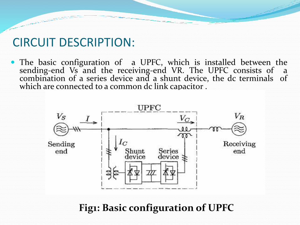
CIRCUIT DESCRIPTION:
The basic configuration of a UPFC, which is installed between thesending-end Vs and the receiving-end VR. The UPFC consists of acombination of a series device and a shunt device, the dc terminals ofwhich are connected to a common dc link capacitor .
Fig1: Basic configuration of UPFC

Automatic UPFC
TYPES OF UPFC CONTROLLERS
Series controllers:
The series controller could be a variable impedance, such as capacitor, reactor, or a power electronics based variable source of main frequency, and harmonic frequencies to serve the desired load.
In principle, all series controllers inject voltage in series with the line. As long as the voltage is in phase quadrature with the line current, the series controller only supplies or consumes variable reactive power.
Series controllers include SSSC, IPFC, TCSC, TSSC, TCSR, and TSSR.

Shunt Controllers.
As in the case of series controllers, the shunt controllers may be variable impedance, variable source, or a combination of these.
In principle, all shunt controllers inject current into the system at the point of connection.
Even a variable shunt impedance connected to the line voltage causes a variable current flow and hence represents injection of current into the line.
Any other phase relationship will involve handling of real power as well. Shunt controllers include STATCOM, TCR, TSR, TSC, and TCBR

OPERATING PRINCIPLE OF UPFC

DISADVANTAGES:
High initial costs
Joints required for contraction and expansion
Generally rough riding quality
High repair cost

THANK YOU