Embed Size (px)
Citation preview
Variable-frequency drive
A variable-frequency drive (VFD) (also termed (disebut) adjustable-frequency drive, variable-
speed drive, AC drive, micro drive or inverter drive) is a type of adjustable-speed drive used in electro-mechanical drive systems to control AC motor speed and torque by varying motor input
frequency and voltage.[1][2][3][4]
VFDs are used in applications ranging from small appliances to the largest of mine mill (pabrik) drives and compressors. However (akan tetapi), around 25% of the world's electrical energy is consumed by electric motors in industrial applications, which are especially conducive for
energy savings using VFDs in centrifugal load service, [5] and VFDs' global market penetration for all applications is still relatively small. That lack of penetration highlights significant energy
efficiency improvement opportunities for retrofitted and new VFD installations.
Over the last four decades, power electronics technology has reduced VFD cost and size and has improved performance through advances in semiconductor switching devices, drive topologies, simulation and control techniques, and control hardware and software.
VFDs are available in a number of different low- and medium-voltage AC-AC and DC-AC topologies
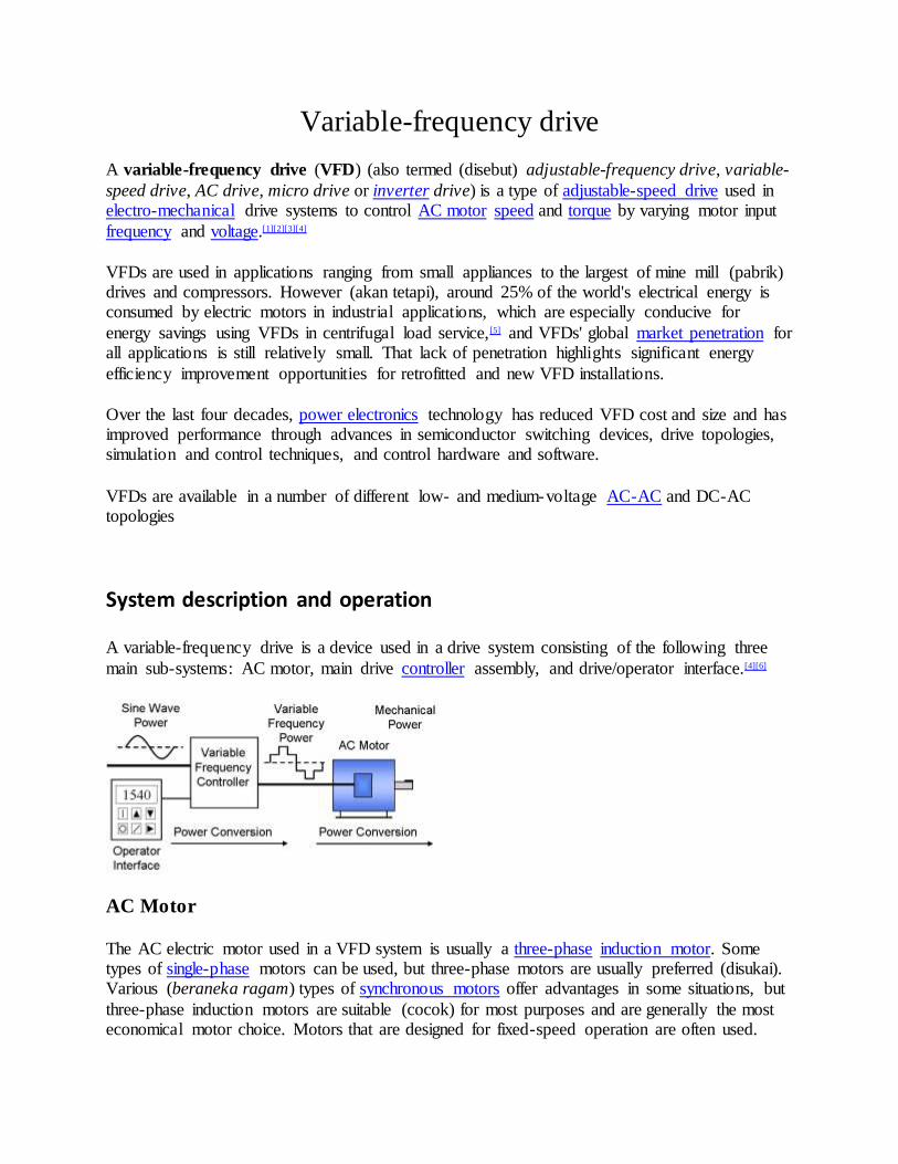
System description and operation
A variable-frequency drive is a device used in a drive system consisting of the following three
main sub-systems: AC motor, main drive controller assembly, and drive/operator interface.[4][6]
AC Motor
The AC electric motor used in a VFD system is usually a three-phase induction motor. Some types of single-phase motors can be used, but three-phase motors are usually preferred (disukai). Various (beraneka ragam) types of synchronous motors offer advantages in some situations, but
three-phase induction motors are suitable (cocok) for most purposes and are generally the most economical motor choice. Motors that are designed for fixed-speed operation are often used.

Elevated (ditinggikan) - voltage stresses imposed (dikenakan) on induction motors that are supplied by VFDs require that such motors be designed for definite (pasti/tertentu)-purpose
inverter-fed duty in accordance with such requirements as Part 31 of NEMA Standard MG-1.[7]
Controller
The VFD controller is a solid-state power electronics conversion system consisting of three
distinct (berbeda) sub-systems: a rectifier bridge converter, a direct current (DC) link, and an inverter. Voltage-source inverter (VSI) drives (see 'Generic topologies' sub-section below) are by far the most common type of drives. Most drives are AC-AC drives in that they convert AC line
input to AC inverter output. However, in some applications such as common DC bus or solar applications, drives are configured as DC-AC drives. The most basic rectifier converter for the
VSI drive is configured as a three-phase, six-pulse, full-wave diode bridge. In a VSI drive, the DC link consists of a capacitor which smooths out the converter's DC output ripple and provides a stiff (kaku) input to the inverter. This filtered DC voltage is converted to quasi-sinusoidal AC
voltage output using the inverter's active switching elements. VSI drives provide higher power factor and lower harmonic distortion than phase-controlled current-source inverter (CSI) and
load-commutated inverter (LCI) drives (see 'Generic topologies' sub-section below). The drive controller can also be configured as a phase converter having single-phase converter input and three-phase inverter output.[8]
Controller advances have exploited dramatic increases in the voltage and current ratings and
switching frequency of solid-state power devices over the past six decades. Introduced in 1983,[9] the insulated-gate bipolar transistor (IGBT) has in the past two decades come to dominate VFDs
as an inverter switching device.[10][11][12]
In variable-torque applications suited (cocok/setara) for Volts-per-Hertz (V/Hz) drive control, AC motor characteristics require that the voltage magnitude of the inverter's output to the motor
be adjusted to match the required load torque in a linear V/Hz relationship. For example, for 460 V, 60 Hz motors, this linear V/Hz relationship is 460/60 = 7.67 V/Hz. While suitable (sementara cocok) in wide-ranging applications, V/Hz control is sub-optimal in high-performance
applications involving (yang melibatkan) low speed or demanding, dynamic speed regulation, positioning, and reversing load requirements. Some V/Hz control drives can also operate in
quadratic V/Hz mode or can even be programmed to suit special multi-point V/Hz paths.[13][14]
The two other drive control platforms, vector control and direct torque control (DTC), adjust the motor voltage magnitude, angle from reference, and frequency[15] so as to precisely control the motor's magnetic flux and mechanical torque.
Although space vector pulse-width modulation (SVPWM) is becoming (menjadi) increasingly
popular,[16] sinusoidal PWM (SPWM) is the most straightforward (mudah) method used to vary drives' motor voltage (or current) and frequency. With SPWM control (see Fig. 1), quasi-
sinusoidal, variable-pulse-width output is constructed from intersections of a saw-toothed carrier frequency signal with a modulating sinusoidal signal which is variable in operating frequency as well as in voltage (or current).[10][17][18]

Operation of the motors above rated nameplate speed (base speed) is possible, but is limited to conditions that do not require more power than the nameplate rating of the motor. This is
sometimes called "field weakening" and, for AC motors, means operating at less than rated V/Hz and above rated nameplate speed. Permanent magnet synchronous motors have quite (agak)
limited field-weakening speed range due to the constant magnet flux linkage. Wound-rotor synchronous motors and induction motors have much wider speed range. For example, a 100 HP, 460 V, 60 Hz, 1775 RPM (4-pole) induction motor supplied with 460 V, 75 Hz (6.134 V/Hz),
would be limited to 60/75 = 80% torque at 125% speed (2218.75 RPM) = 100% power.[19] At higher speeds, the induction motor torque has to be limited further due to the lowering of the
breakaway torque[a] of the motor. Thus, rated power can be typically produced only up to 130-150% of the rated nameplate speed. Wound-rotor synchronous motors can be run at even higher speeds. In rolling mill drives, often 200-300% of the base speed is used. The mechanical strength
of the rotor limits the maximum speed of the motor.
An embedded microprocessor governs (mangatur/memerintah) the overall operation of the VFD
controller. Basic programming of the microprocessor is provided (disediakan) as user-inaccessible (yang tidak dapat dikases) firmware. User programming of display, variable, and
function block parameters is provided to control, protect, and monitor the VFD, motor, and driven equipment.[10][20]
The basic drive controller can be configured to selectively include such optional power
components and accessories as follows:
Connected upstream of converter -- circuit breaker or fuses, isolation contactor, EMC filter, line reactor, passive filter
Connected to DC link -- braking chopper, braking resistor Connected downstream of inverter -- output reactor, sine wave filter, dV/dt filter. [b][22]

Operator interface
The operator interface provides a means for an operator to start and stop the motor and adjust the
operating speed. Additional operator control functions might include reversing, and switching between manual speed adjustment and automatic control from an external process control signal.
The operator interface often includes an alphanumeric display and/or indication lights and meters to provide information about the operation of the drive. An operator interface keypad and display unit is often provided on the front of the VFD controller as shown in the photograph above. The
keypad display can often be cable-connected and mounted a short distance from the VFD controller. Most are also provided with input and output (I/O) terminals for connecting
pushbuttons, switches, and other operator interface devices or control signals. A serial communications port is also often available to allow the VFD to be configured, adjusted, monitored, and controlled using a computer.[10][23][24]
Drive operation
Referring to the accompanying chart, drive applications can be categorized as single-quadrant, two-quadrant, or four-quadrant; the chart's four quadrants are defined as follows:[25][26][27]
Quadrant I -- Driving or motoring,[28] forward accelerating quadrant with positive speed and torque
Quadrant II -- Generating or braking, forward braking-decelerating quadrant with
positive speed and negative torque Quadrant III - Driving or motoring, reverse accelerating quadrant with negative speed
and torque Quadrant IV - Generating or braking, reverse braking-decelerating quadrant with
negative speed and positive torque.
Most applications involve single-quadrant loads operating in quadrant I, such as in variable-
torque (e.g. centrifugal pumps or fans) and certain constant-torque (e.g. extruders) loads.

Certain applications involve two-quadrant loads operating in quadrant I and II where the speed is positive but the torque changes polarity as in case of a fan decelerating faster than natural
mechanical losses. Some sources define two-quadrant drives as loads operating in quadrants I and III where the speed and torque is same (positive or negative) polarity in both directions.
Certain high-performance applications involve four-quadrant loads (Quadrants I to IV) where the
speed and torque can be in any direction such as in hoists, elevators, and hilly conveyors. Regeneration can occur only in the drive's DC link bus when inverter voltage is smaller in magnitude than the motor back-EMF and inverter voltage and back-EMF are the same polarity.[29]
In starting a motor, a VFD initially applies a low frequency and voltage, thus avoiding high inrush current associated with direct-on-line starting. After the start of the VFD, the applied frequency and voltage are increased at a controlled rate or ramped up to accelerate the load. This
starting method typically allows a motor to develop 150% of its rated torque while the VFD is drawing less than 50% of its rated current from the mains in the low-speed range. A VFD can be
adjusted to produce a steady 150% starting torque from standstill right up to full speed. [30] However, motor cooling deteriorates and can result in overheating as speed decreases such that prolonged low-speed operation with significant torque is not usually possible without separately
motorized fan ventilation.
With a VFD, the stopping sequence is just the opposite as the starting sequence. The frequency and voltage applied to the motor are ramped down at a controlled rate. When the frequency
approaches zero, the motor is shut off. A small amount of braking torque is availab le to help decelerate the load a little faster than it would stop if the motor were simply switched off and allowed to coast. Additional braking torque can be obtained by adding a braking circuit (resistor
controlled by a transistor) to dissipate the braking energy. With a four-quadrant rectifier (active front-end), the VFD is able to brake the load by applying a reverse torque and injecting the
energy back to the AC line.
Benefits
Energy savings
Many fixed-speed motor load applications that are supplied direct from AC line power can save energy when they are operated at variable speed by means of VFD. Such energy cost savings are
especially pronounced in variable-torque centrifugal fan and pump applications, where the load's torque and power vary with the square and cube, respectively, of the speed. This change gives a
large power reduction compared to fixed-speed operation for a relatively small reduction in speed. For example, at 63% speed a motor load consumes only 25% of its full-speed power. This reduction is in accordance with affinity laws that define the relationship between various
centrifugal load variables.
In the United States, an estimated 60-65% of electrical energy is used to supply motors, 75% of which are variable-torque fan, pump, and compressor loads.[31] Eighteen percent of the energy

used in the 40 million motors in the U.S. could be saved by efficient energy improvement technologies such as VFDs.[32][33]
Only about 3% of the total installed base of AC motors are provided with AC drives.[34] However,
it is estimated that drive technology is adopted in as many as 30-40% of all newly installed motors.[35]
An energy consumption breakdown of the global population of AC motor installations is as
shown in the following table
Global population of motors, 2009[36]
Small General Purpose - Medium-Size Large
Power 10W - 750W 0.75 kW - 375 kW 375 kW - 10000 kW
Phase, voltage 1-ph., <240V 3-ph., 200V to 1kV 3-ph., 1kV to 20kV
% total motor energy 9% 68% 23%
Total stock 2 billion 230 million 0.6 million
Control performance
AC drives are used to bring about process and quality improvements in industrial and commercial applications' acceleration, flow, monitoring, pressure, speed, temperature, tension,
and torque.[37]
Fixed-speed loads subject the motor to a high starting torque and to current surges that are up to eight times the full- load current. AC drives instead gradually ramp the motor up to operating speed to lessen mechanical and electrical stress, reducing maintenance and repair costs, and
extending the life of the motor and the driven equipment.
Variable-speed drives can also run a motor in specialized patterns to further minimize mechanical and electrical stress. For example, an S-curve pattern can be applied to a conveyor
application for smoother deceleration and acceleration control, which reduces the backlash that can occur when a conveyor is accelerating or decelerating.
Performance factors tending to favor the use of DC drives over AC drives include such
requirements as continuous operation at low speed, four-quadrant operation with regeneration, frequent acceleration and deceleration routines, and need for the motor to be protected for a hazardous area.[38] The following table compares AC and DC drives according to certain key
parameters:[39][40][41]
Drive type DC AC VFD AC VFD AC VFD AC VFD

Control platform Brush type DC V/Hz control Vector control Vector control Vector control
Control criteria Closed-loop Open-loop Open-loop Closed-loop Open-loop w. HFI ̂
Motor DC IM IM IM Interior PM
Typical speed regulation (%) 0.01 1 0.5 0.01 0.02
Typical speed range at constant torque (%) 0-100 10-100 3-100 0-100 0-100
Min. speed at 100% torque (% of base) Standstill 8% 2% Standstill Standstill (200%)
Multiple-motor operation recommended No Yes No No No
Fault protection (Fused only or inherent to drive) Fused only Inherent Inherent Inherent Inherent
Maintenance (Brushes) Low Low Low Low
Feedback device Tachometer or encoder N/A N/A Encoder N/A
^ High-frequency injection
VFD types and ratings
Generic topologies
Topology of VSI drive
Topology of CSI drive
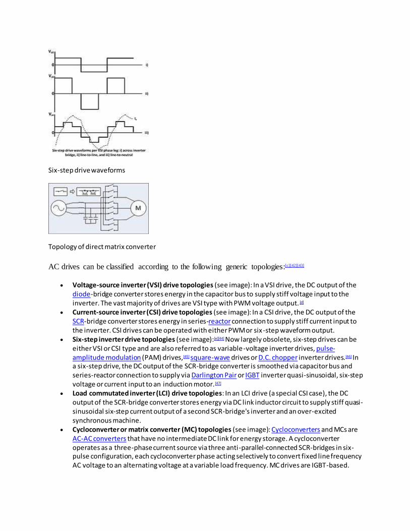
Six-step drive waveforms
Topology of direct matrix converter
AC drives can be classified according to the following generic topologies:[c][42][43]
Voltage-source inverter (VSI) drive topologies (see image): In a VSI drive, the DC output of the diode-bridge converter stores energy in the capacitor bus to supply stiff voltage input to the inverter. The vast majority of drives are VSI type with PWM voltage output. [d]
Current-source inverter (CSI) drive topologies (see image): In a CSI drive, the DC output of the SCR-bridge converter stores energy in series-reactor connection to supply stiff current input to the inverter. CSI drives can be operated with either PWM or six -step waveform output.
Six-step inverter drive topologies (see image):[e][44] Now largely obsolete, six-step drives can be either VSI or CSI type and are also referred to as variable-voltage inverter drives, pulse-amplitude modulation (PAM) drives,[45] square-wave drives or D.C. chopper inverter drives.[46] In a six-step drive, the DC output of the SCR-bridge converter is smoothed via capacitor bus and series-reactor connection to supply via Darlington Pair or IGBT inverter quasi-sinusoidal, six-step voltage or current input to an induction motor. [47]
Load commutated inverter (LCI) drive topologies: In an LCI drive (a special CSI case), the DC output of the SCR-bridge converter stores energy via DC link inductor circuit to supply stiff quasi-sinusoidal six-step current output of a second SCR-bridge's inverter and an over-excited synchronous machine.
Cycloconverter or matrix converter (MC) topologies (see image): Cycloconverters and MCs are AC-AC converters that have no intermediate DC link for energy storage. A cycloconverter operates as a three-phase current source via three anti-parallel-connected SCR-bridges in six-pulse configuration, each cycloconverter phase acting selectively to convert fixed line frequency AC voltage to an alternating voltage at a variable load frequency. MC drives are IGBT-based.
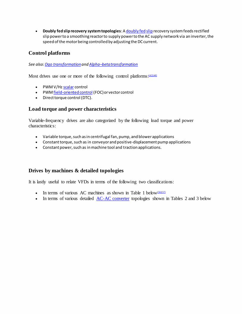
Doubly fed slip recovery system topologies: A doubly fed slip recovery system feeds rectified slip power to a smoothing reactor to supply power to the AC supply network via an inverter, the speed of the motor being controlled by adjusting the DC current.
Control platforms
See also: Dqo transformation and Alpha–beta transformation
Most drives use one or more of the following control platforms:[42][48]
PWM V/Hz scalar control PWM field-oriented control (FOC) or vector control Direct torque control (DTC).
Load torque and power characteristics
Variable-frequency drives are also categorized by the following load torque and power characteristics:
Variable torque, such as in centrifugal fan, pump, and blower applications Constant torque, such as in conveyor and positive-displacement pump applications Constant power, such as in machine tool and traction applications.
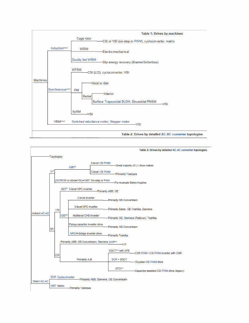
Drives by machines & detailed topologies
It is lastly useful to relate VFDs in terms of the following two classifications:
In terms of various AC machines as shown in Table 1 below[56][57]
In terms of various detailed AC-AC converter topologies shown in Tables 2 and 3 below

Application considerations
AC line harmonics
Note of clarification:.[f]
While harmonics in the PWM output can easily be filtered by carrier-frequency-related filter inductance to supply near-sinusoidal currents to the motor load,[17] the VFD's diode-bridge rectifier converts AC line voltage to DC voltage output by super-imposing non-linear half-phase
current pulses thus creating harmonic current distortion, and hence voltage distortion, of the AC line input. When the VFD loads are relatively small in comparison to the large, stiff power
system available from the electric power company, the effects of VFD harmonic distortion of the AC grid can often be within acceptable limits. Furthermore, in low-voltage networks, harmonics caused by single-phase equipment such as computers and TVs are partially cancelled by three-
phase diode bridge harmonics because their 5th and 7th harmonics are in counterphase. [63] However, when the proportion of VFD and other non-linear load compared to total load or of
non-linear load compared to the stiffness at the AC power supply, or both, is relatively large enough, the load can have a negative impact on the AC power waveform available to other power company customers in the same grid.
When the power company's voltage becomes distorted due to harmonics, losses in other loads such as normal fixed-speed AC motors are increased. This condition may lead to overheating and shorter operating life. Also, substation transformers and compensation capacitors are affected
negatively. In particular, capacitors can cause resonance conditions that can unacceptably magnify harmonic levels. In order to limit the voltage distortion, owners of VFD load may be
required to install filtering equipment to reduce harmonic distortion below acceptable limits. Alternatively, the utility may adopt a solution by installing filtering equipment of its own at substations affected by the large amount of VFD equipment being used. In high-power
installations, harmonic distortion can be reduced by supplying multi-pulse rectifier-bridge VFDs from transformers with multiple phase-shifted windings.[64]
It is also possible to replace the standard diode-bridge rectifier with a bi-directional IGBT
switching device bridge mirroring the standard inverter which uses IGBT switching device output to the motor. Such rectifiers are referred to by various designations including active
infeed converter (AIC), active rectifier, IGBT supply unit (ISU), active front end (AFE), or four-quadrant operation. With PWM control and a suitable input reactor, an AFE's AC line current waveform can be nearly sinusoidal. AFE inherently regenerates energy in four-quadrant mode
from the DC side to the AC grid. Thus, no braking resistor is needed, and the efficiency of the drive is improved if the drive is frequently required to brake the motor.
Two other harmonics mitigation techniques exploit use of passive or active filters connected to a
common bus with at least one VFD branch load on the bus. Passive filters involve the design of one or more low-pass LC filter traps, each trap being tuned as required to a harmonic frequency
(5th, 7th, 11th, 13th, . . . kq+/-1, where k=integer, q=pulse number of converter).[65]
It is very common practice for power companies or their customers to impose harmonic distortion limits based on IEC or IEEE standards. For example, IEEE Standard 519 limits at the customer's connection point call for the maximum individual frequency voltage harmonic to be
no more than 3% of the fundamental and call for the voltage total harmonic distortion (THD) to be no more than 5% for a general AC power supply system.[66]
Long-lead effects
[67][68][69][70]
The carrier-frequency pulsed output voltage of a PWM VFD causes rapid rise times in these pulses, the transmission line effects of which must be considered. Since the transmission- line
impedance of the cable and motor are different, pulses tend to reflect back from the motor terminals into the cable. The resulting voltages can produce overvoltages equal to twice the DC bus voltage or up to 3.1 times the rated line voltage for long cable runs, putting high stress on the
cable and motor windings, and eventual insulation failure. Note that standards for three-phase motors rated 230 V or less adequately protect against such long-lead overvoltages. On 460 V or
575 V systems and inverters with 3rd-generation 0.1-microsecond-rise-time IGBTs, the maximum recommended cable distance between VFD and motor is about 50 m or 150 feet. Solutions to overvoltages caused by long lead lengths include minimizing cable distance,
lowering carrier frequency, installing dV/dt filters, using inverter-duty-rated motors (that are rated 600 V to withstand pulse trains with rise time less than or equal to 0.1 microsecond, of
1,600 V peak magnitude), and installing LCR low-pass sine wave filters.[71][72][73] Regarding lowering of carrier frequency, note that audible noise is noticeably increased for carrier frequencies less than about 6 kHz and is most noticeable at about 3 kHz. Note also that selection
of optimum PWM carrier frequency for AC drives involves balancing noise, heat, motor insulation stress, common-mode voltage-induced motor bearing current damage, smooth motor
operation, and other factors. Further harmonics attenuation can be obtained by using an LCR low-pass sine wave filter or dV/dt filter.

Motor bearing currents
Main article: Shaft voltage
PWM drives are inherently associated with high-frequency common-mode voltages and currents
which may cause trouble with motor bearings.[74] When these high-frequency voltages find a path to earth through a bearing, transfer of metal or electrical discharge machining (EDM) sparking
occurs between the bearing's ball and the bearing's race. Over time, EDM-based sparking causes erosion in the bearing race that can be seen as a fluting pattern. In large motors, the stray
capacitance of the windings provides paths for high-frequency currents that pass through the motor shaft ends, leading to a circulating type of bearing current. Poor grounding of motor stators can lead to shaft-to-ground bearing currents. Small motors with poorly grounded driven
equipment are susceptible to high-frequency bearing currents.[75]
Prevention of high-frequency bearing current damage uses three approaches: good cabling and grounding practices, interruption of bearing currents, and filtering or damping of common-mode
currents. Good cabling and grounding practices can include use of shielded, symmetrical-geometry power cable to supply the motor, installation of shaft grounding brushes, and conductive bearing grease. Bearing currents can be interrupted by installation of insulated
bearings and specially designed electrostatic-shielded induction motors. Filtering and damping high-frequency bearing, or, instead of using standard 2-level inverter drives, using either 3-level
inverter drives or matrix converters.[75][76]
Since inverter-fed motor cables' high-frequency current spikes can interfere with other cabling in facilities, such inverter- fed motor cables should not only be of shielded, symmetrical-geometry
design but should also be routed at least 50 cm away from signal cables.[77]
Dynamic braking
See also: Dynamic braking and Regenerative braking
Torque generated by the drive causes the induction motor to run at synchronous speed less the
slip. If the load drives the motor faster than synchronous speed, the motor acts as a generator, converting mechanical power back to electrical power. This power is returned to the drive's DC link element (capacitor or reactor). A DC-link-connected electronic power switch or braking DC
chopper controls dissipation of this power as heat in a set of resistors. Cooling fans may be used to prevent resistor overheating.[27]
Dynamic braking wastes braking energy by transforming it to heat. By contrast, regenerative
drives recover braking energy by injecting this energy into the AC line. The capital cost of regenerative drives is, however, relatively high.[78]

Regenerative drives
Regenerative AC drives have the capacity to recover the braking energy of a load moving faster
than the designated motor speed (an overhauling load) and return it to the power system.
Cycloconverter, Scherbius, matrix, CSI, and LCI drives inherently allow return of energy from the load to the line, while voltage-source inverters require an additional converter to return
energy to the supply.[80][81]
Regeneration is useful in VFDs only where the value of the recovered energy is large compared to the extra cost of a regenerative system,[80] and if the system requires frequent braking and starting. Regenerative VFDs are widely used where speed control of overhauling loads is
required.[2][3][82]
Some examples:
Conveyor belt drives for manufacturing, which stop every few minutes. While stopped, parts are assembled correctly; once that is done, the belt moves on.
A crane, where the hoist motor stops and reverses frequently, and braking is required to slow the load during lowering.
Plug-in and hybrid electric vehicles of all types (see image and Hybrid Synergy Drive).
JOB DESCRIPTION
Application Engineer for Drives and Motion Control
Area of Responsibilities :
• Manage motion control applications with a focus on General Motion Control • Implement, modify, specify and develop motion control applications for the local market • Specify Siemens motion control applications for dedicated customers
• Train local sales, SI, OEM, End Customers on Siemens motion control applications • Supervise and assist during the technical implementation phase • Manage the product portfolio required for motion control applications • Customer consultation towards motion control applications • Coordinate between country divisions, headquarter, Siemens affiliates
Job Qualifications :
• University Degree in Electrical Engineering or equivalent • Minimum 3 years experience in Motion Control/Variable Speed Drives/PLC/Automation Industry with focus on technical applications • Ability to analyze and fulfill technical specifications • Independent, with strong oral & written communication skills in English • Able to work with people of different cultures • Team player with good communication skills
• Maintain and live the Siemens values • Willing to travel within Indonesia and occasionally within ASEAN and to Europe
Only shortlisted candidates will be notified
JOB DESCRIPTION
Area of Responsibilities
• Sales of all Motion Control products with a focus on variable speed drives • Achieve the annual personal and group targets for New Orders, Turnover, Profit Loss • Effective and efficient management of the assigned key accounts • Development of assigned key accounts • Budget and forecast planning • Maintain data quality in CRM Management tool • Develop new customers and opportunities
Job Requirements :
• University Degree in Electrical Engineering or equiva lent • Minimum 3 years experience in Motion Control/Variable Speed Drives/PLC/Automation Industry • Independent, with strong oral & written communication skills in English • Able to work with people of different cultures
• Team player with good communication skills • Entrepreneurial spirit • Maintain and live the Siemens values • Willing to travel within Indonesia and occasionally within ASEAN and to Europe
Only shortlisted candidates will be notified.