Embed Size (px)
Citation preview
Unit 2
Data Link Control
Topics to be covered in this unit . . . . . . . . .
Framing
Flow Control
Error Control
Protocols
~ for Noiseless ( ideal ) Channels
~ for Noisy (practical or real ) Channels
HDLC Protocol
2-1 FRAMING
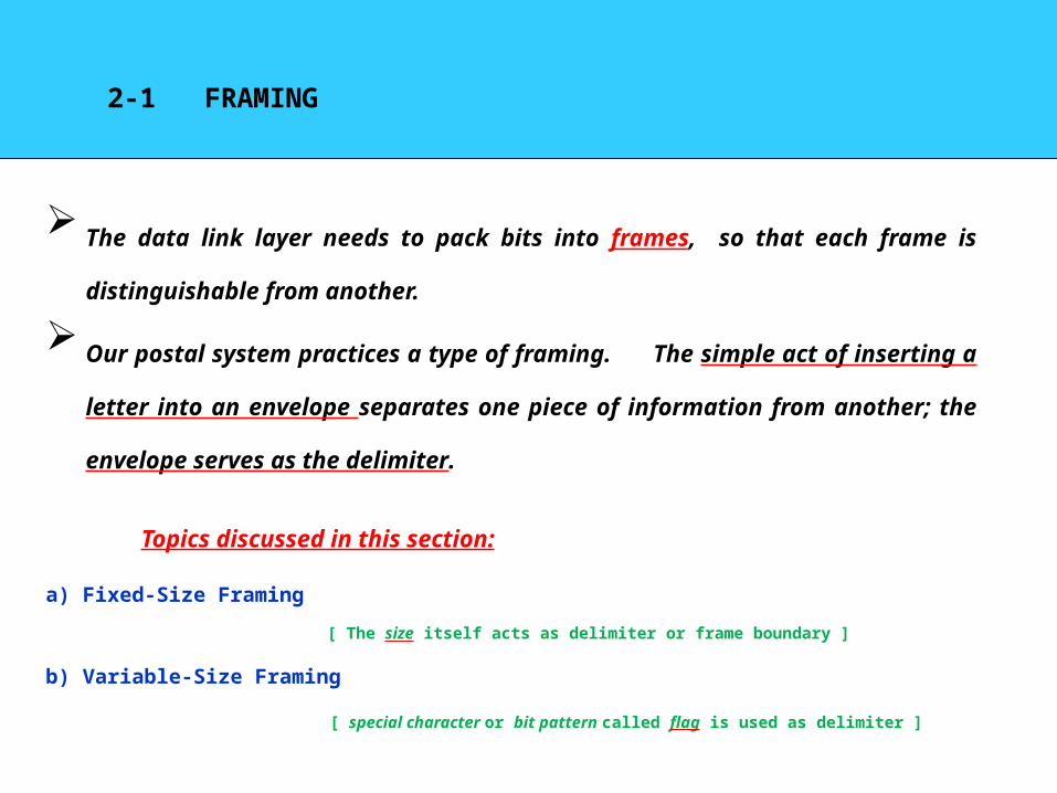
The data link layer needs to pack bits into frames, so that each frame is distinguishable
from another.
Our postal system practices a type of framing. The simple act of inserting a letter into
an envelope separates one piece of information from another; the envelope serves as the
delimiter.
a) Fixed-Size Framing
[ The size itself acts as delimiter or frame boundary ]
b) Variable-Size Framing
[ special character or bit pattern called flag is used as delimiter ]
Topics discussed in this section:
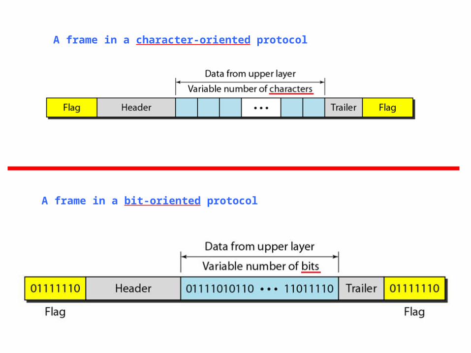
A frame in a character-oriented protocol
A frame in a bit-oriented protocol
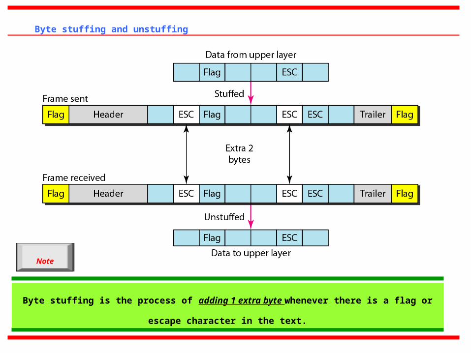
Byte stuffing and unstuffing
Byte stuffing is the process of adding 1 extra byte whenever there is a flag or escape character in
the text.
Note
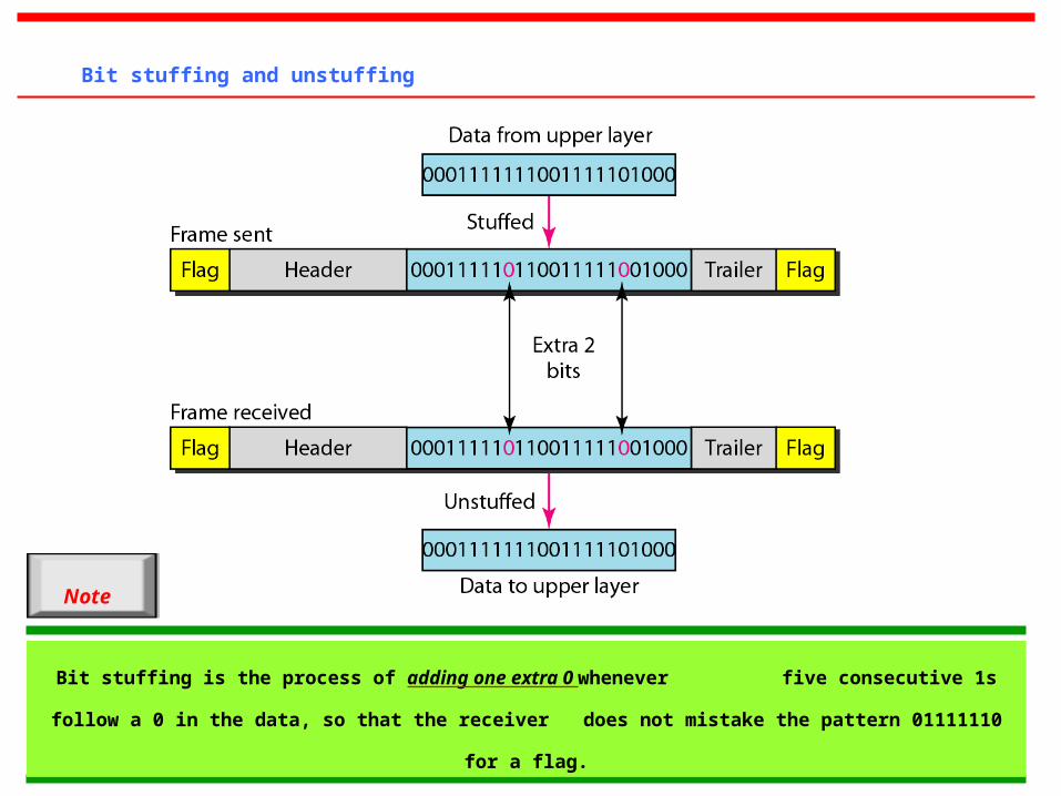
Bit stuffing and unstuffing
Bit stuffing is the process of adding one extra 0 whenever five consecutive 1s follow a 0 in the data, so
that the receiver does not mistake the pattern 01111110 for a flag.
Note
2-2 FLOW AND ERROR CONTROL
The most important responsibilities of the data link layer are flow control and error control.
Collectively, these functions are known as data link control.
a) Flow Control
b) Error Control
Topics discussed in this section:
Flow control refers to a set of procedures used to restrict the amount of
data
that the sender can send before
waiting for acknowledgment.
Error control in the data link layer is based on automatic repeat request
(ARQ), which is the retransmission of data.
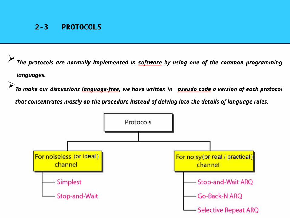
2-3 PROTOCOLS
The protocols are normally implemented in software by using one of the common programming languages.
To make our discussions language-free, we have written in pseudo code a version of each protocol that
concentrates mostly on the procedure instead of delving into the details of language rules.
2-3 a) NOISELESS CHANNELS
Let us first assume we have an ideal channel in which no frames are lost, duplicated, or
corrupted.
In other words, the channel is error free and as a result we don’t require any error
control mechanism in the corresponding protocols.
We introduce two protocols for this type of channel.
a) Simplest Protocol
b) Stop-and-Wait Protocol
Topics discussed in this section:
1. Simplest Protocol
We assume that the receiver can immediately handle any frame it receives with a processing time that is small
enough to be negligible.
In other words, the receiver can never be overwhelmed with incoming frames.
Hence there is no need for flow control in this scheme.
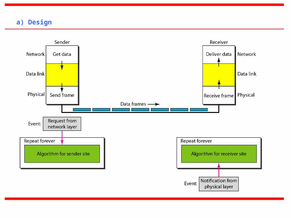
a) Design
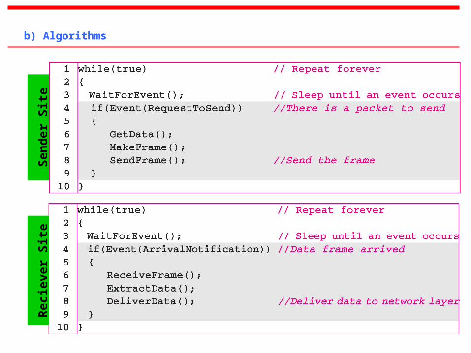
b) Algorithms S
end
er S
ite
Rec
ieve
r S
ite
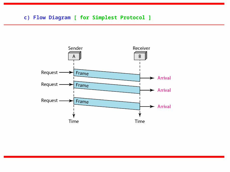
c) Flow Diagram [ for Simplest Protocol ]
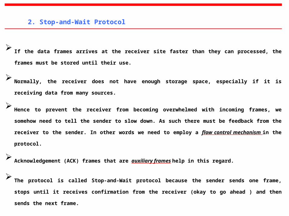
2. Stop-and-Wait Protocol
If the data frames arrives at the receiver site faster than they can processed, the frames must be stored until their use.
Normally, the receiver does not have enough storage space, especially if it is receiving data from many sources.
Hence to prevent the receiver from becoming overwhelmed with incoming frames, we somehow need to tell the sender to
slow down. As such there must be feedback from the receiver to the sender. In other words we need to employ a flow
control mechanism in the protocol.
Acknowledgement (ACK) frames that are auxiliary frames help in this regard.
The protocol is called Stop-and-Wait protocol because the sender sends one frame, stops until it receives confirmation from
the receiver (okay to go ahead ) and then sends the next frame.
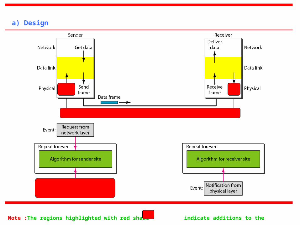
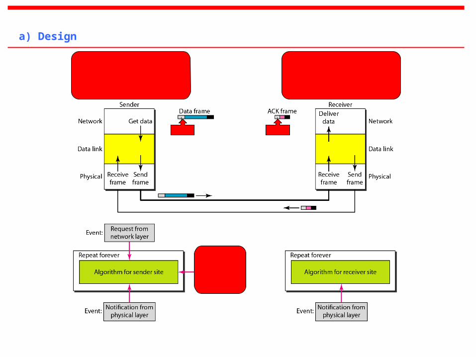
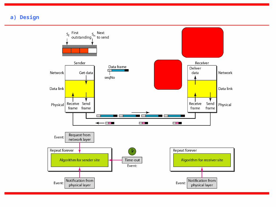
a) Design
Note :The regions highlighted with red shade indicate additions to the previous protocol.
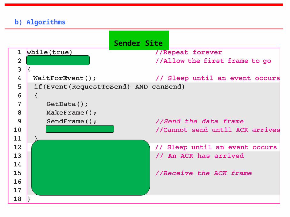
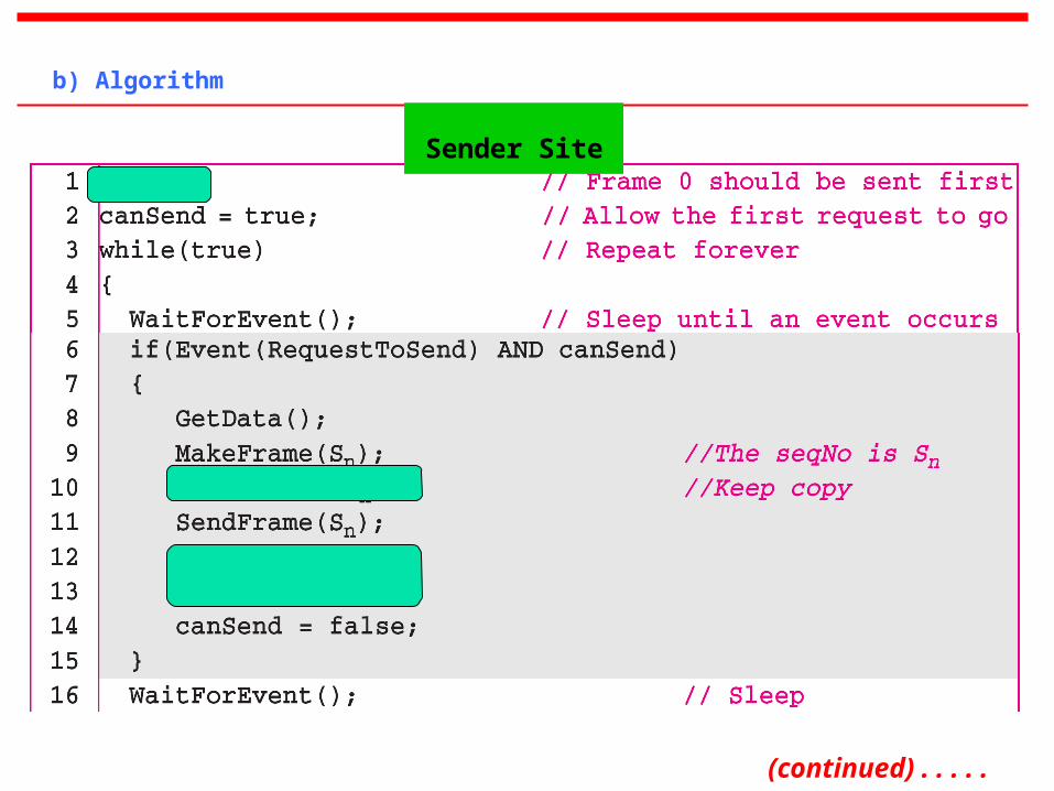
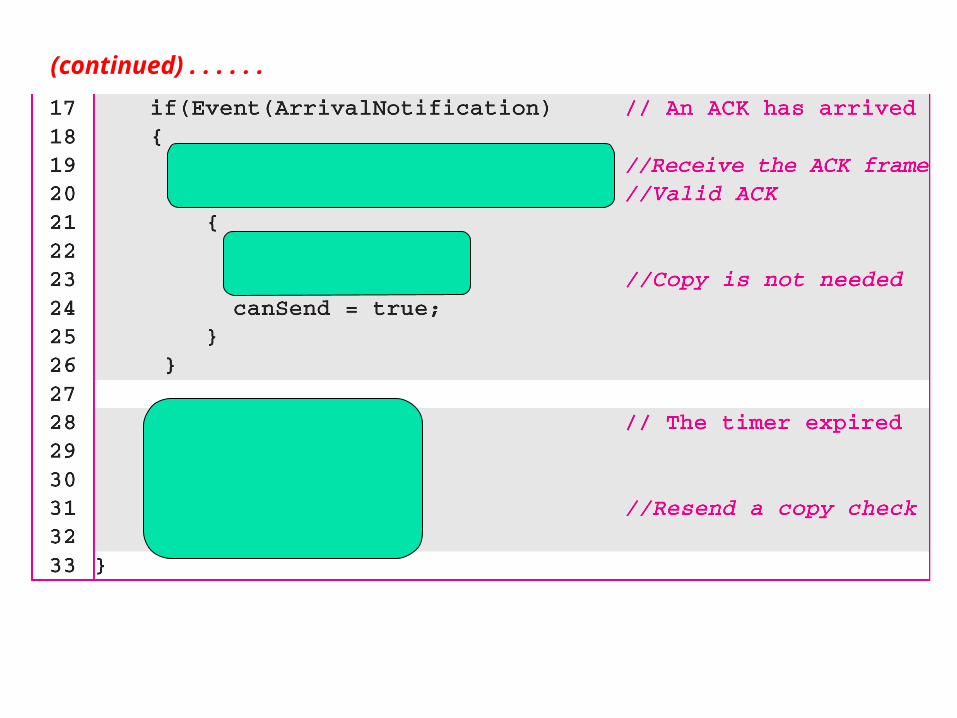
b) Algorithms
Sender Site
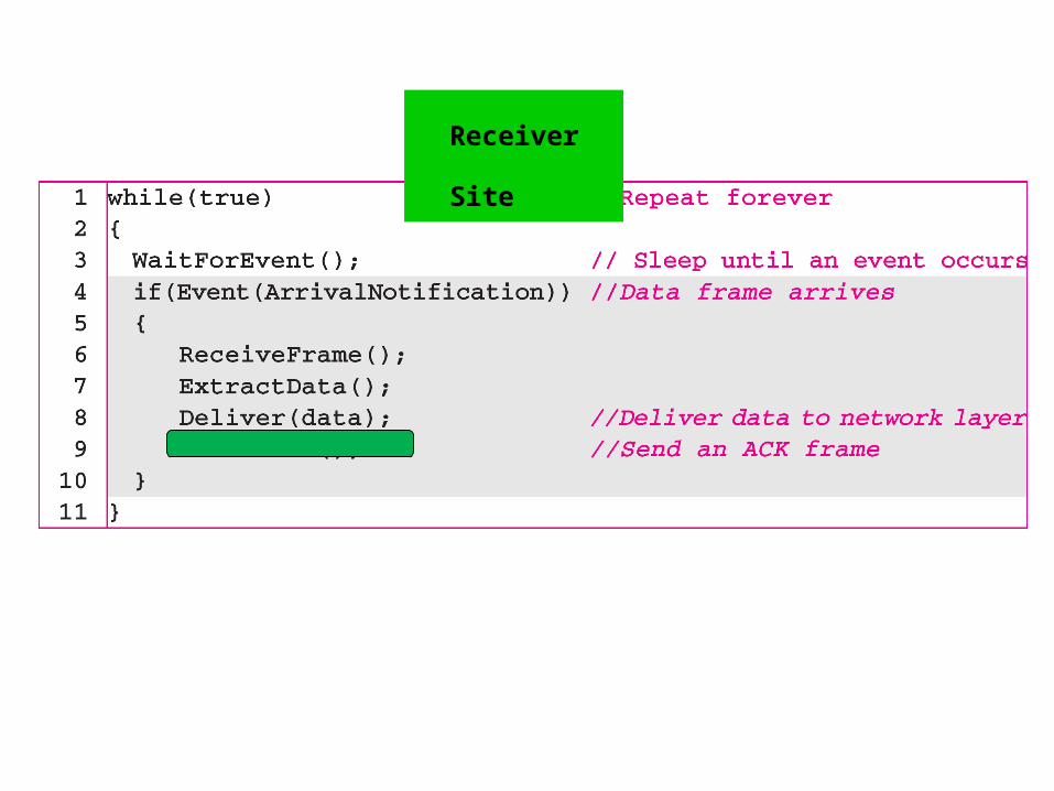
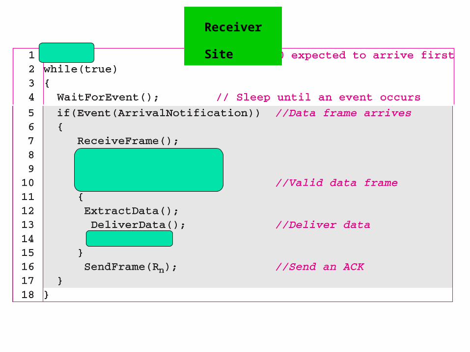
Receiver Site
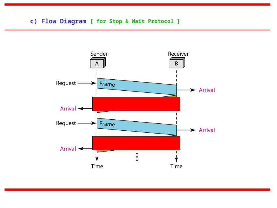
c) Flow Diagram [ for Stop & Wait Protocol ]
2-3 b) NOISY CHANNELS
Although the Stop-and-Wait Protocol gives us an idea of how to add flow control to its
predecessor, noiseless channels are nonexistent. We discuss three protocols in this section that
use error control.
a) Stop-and-Wait Automatic Repeat Request
b) Go-Back-N Automatic Repeat Request
c) Selective Repeat Automatic Repeat Request
Topics discussed in this section:
Error correction in Stop-and-Wait ARQ is done by keeping a copy of the sent frame and
retransmitting of the frame when the timer expires.
In Stop-and-Wait ARQ, we use sequence numbers to number the frames. The sequence numbers
are based on modulo-2 arithmetic.
In Stop-and-Wait ARQ, the acknowledgment number always announces in modulo-2 arithmetic
the sequence number of the next frame expected.
3. Stop-and-Wait ARQ Protocol
a) Design
(continued) . . . . .
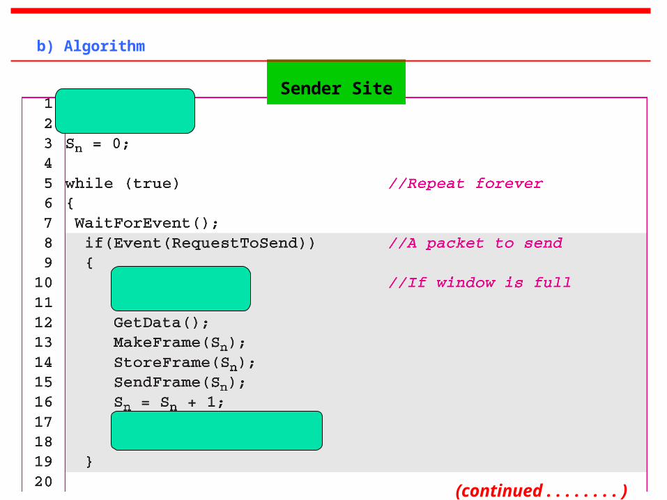
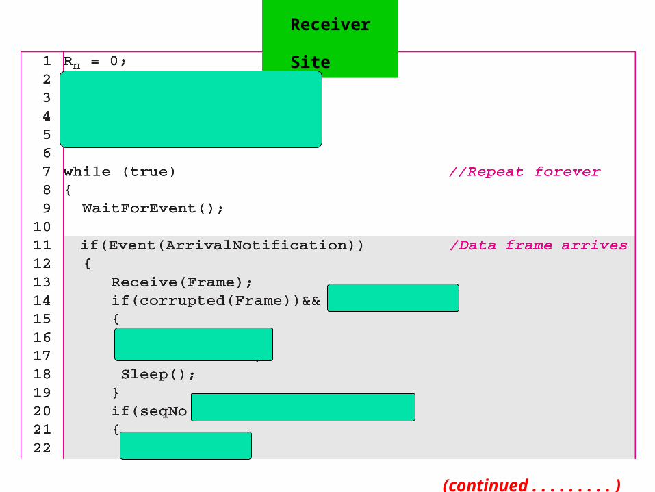
b) Algorithm
Sender Site
(continued) . . . . . .
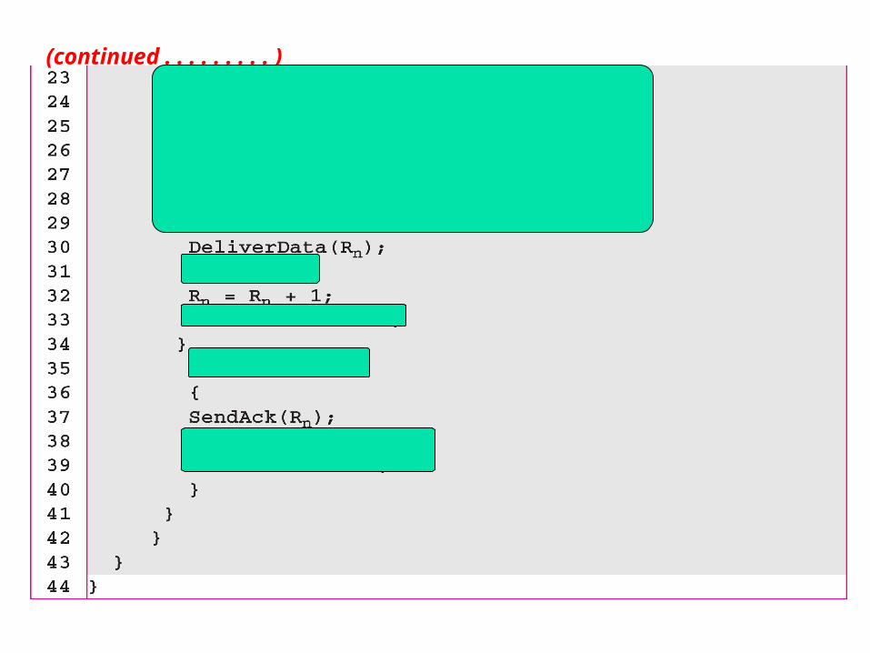
Receiver Site
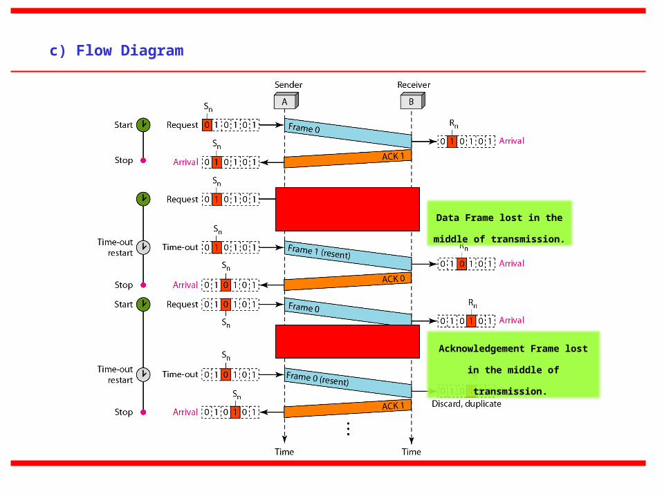
c) Flow Diagram
Data Frame lost in the middle
of transmission.
Acknowledgement Frame lost in
the middle of transmission.
Efficiency & Pipelining
The Stop & Wait ARQ discussed in the previous section is very inefficient if our channel is thick and long.
By thick it is meant that the channel has a large bandwidth; by long, we mean the round-trip delay is long.
The product of these two is called the bandwidth-delay product. The bandwidth-delay product is a measure
of the number of bits we can send out of our system while waiting for news from the receiver.
Pipelining is a technique in which a task is often begun before the previous task has ended. This is known
as pipelining.
If we employ pipelining concept then several frames can be sent before we receive news about the previous
frames.
Pipelining improves efficiency of the transmission if the number of bits in transition is large with respect to
the bandwidth-delay product.
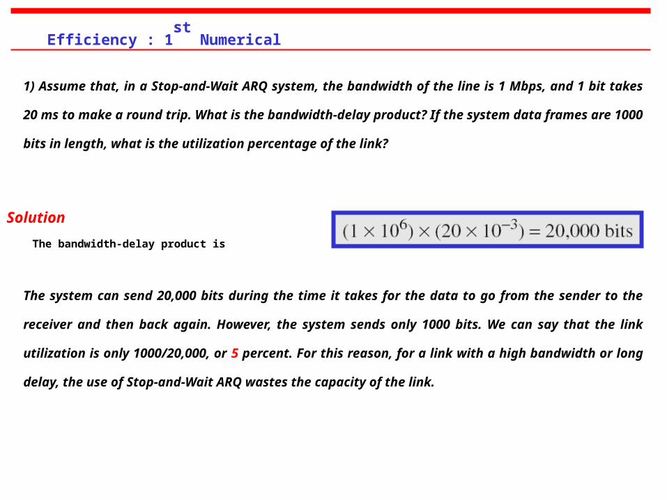
1) Assume that, in a Stop-and-Wait ARQ system, the bandwidth of the line is 1 Mbps, and 1 bit takes 20 ms to make a
round trip. What is the bandwidth-delay product? If the system data frames are 1000 bits in length, what is the
utilization percentage of the link?
Solution
The bandwidth-delay product is
Efficiency : 1st
Numerical
The system can send 20,000 bits during the time it takes for the data to go from the sender to the receiver and then
back again. However, the system sends only 1000 bits. We can say that the link utilization is only 1000/20,000, or 5
percent. For this reason, for a link with a high bandwidth or long delay, the use of Stop-and-Wait ARQ wastes the
capacity of the link.
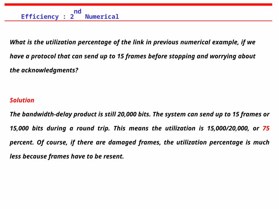
What is the utilization percentage of the link in previous numerical example, if we have a
protocol that can send up to 15 frames before stopping and worrying about the
acknowledgments?
Solution
The bandwidth-delay product is still 20,000 bits. The system can send up to 15 frames or 15,000 bits
during a round trip. This means the utilization is 15,000/20,000, or 75 percent. Of course, if there
are damaged frames, the utilization percentage is much less because frames have to be resent.
Efficiency : 2nd
Numerical
4. Go-Back-N ARQ Protocol
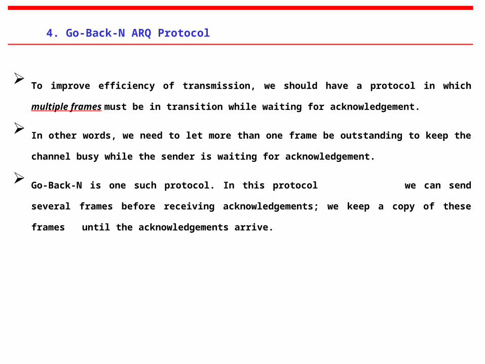
To improve efficiency of transmission, we should have a protocol in which multiple frames must
be in transition while waiting for acknowledgement.
In other words, we need to let more than one frame be outstanding to keep the channel busy while
the sender is waiting for acknowledgement.
Go-Back-N is one such protocol. In this protocol we can send several frames before
receiving acknowledgements; we keep a copy of these frames until the acknowledgements
arrive.
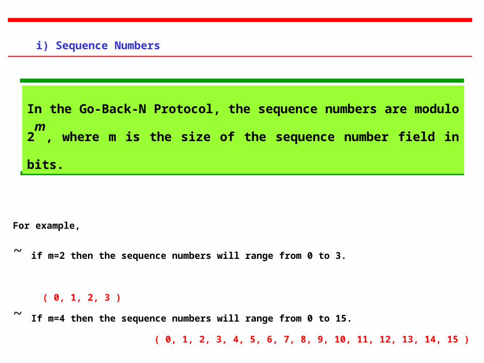
In the Go-Back-N Protocol, the sequence numbers are modulo 2m
, where
m is the size of the sequence number field in bits.
i) Sequence Numbers
For example,
~ if m=2 then the sequence numbers will range from 0 to 3.
( 0, 1, 2, 3 )
~ If m=4 then the sequence numbers will range from 0 to 15.
( 0, 1, 2, 3, 4, 5, 6, 7, 8, 9, 10, 11, 12, 13, 14, 15 )
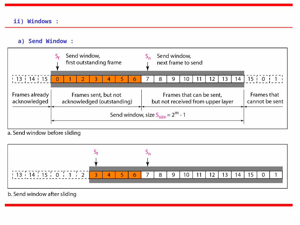
ii) Windows :
a) Send Window :
The send window is an abstract concept defining an imaginary box of
size 2m
− 1 with three variables: Sf, Sn, and Ssize.
The send window can slide one
or more slots when a valid acknowledgment arrives.
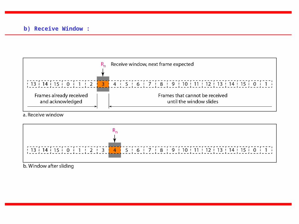
b) Receive Window :
The receive window is an abstract concept defining an imaginary box of size 1 with one single variable
Rn. The window slides when a correct frame has arrived; sliding occurs one slot at a time.
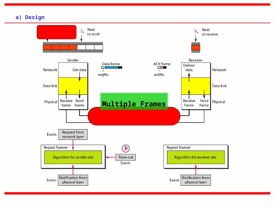
a) Design
Multiple Frames
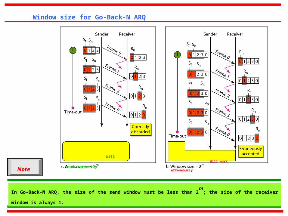
Window size for Go-Back-N ARQ
In Go-Back-N ARQ, the size of the send window must be less than 2m
; the size of the receiver window is always 1.
Note
Will work correctly
Will work erroneously
(continued . . . . . . . . )
b) Algorithm
Sender Site
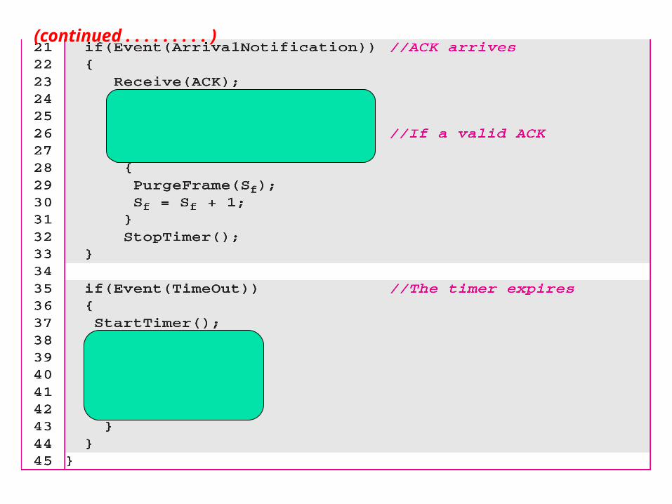
(continued . . . . . . . . . )
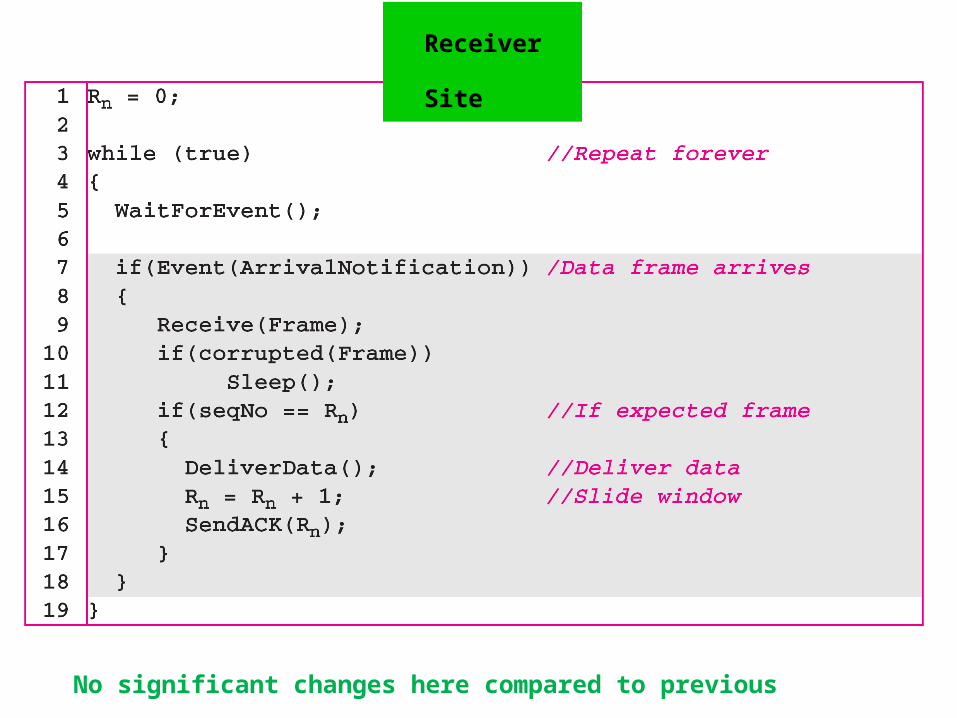
Receiver Site
No significant changes here compared to previous protocol
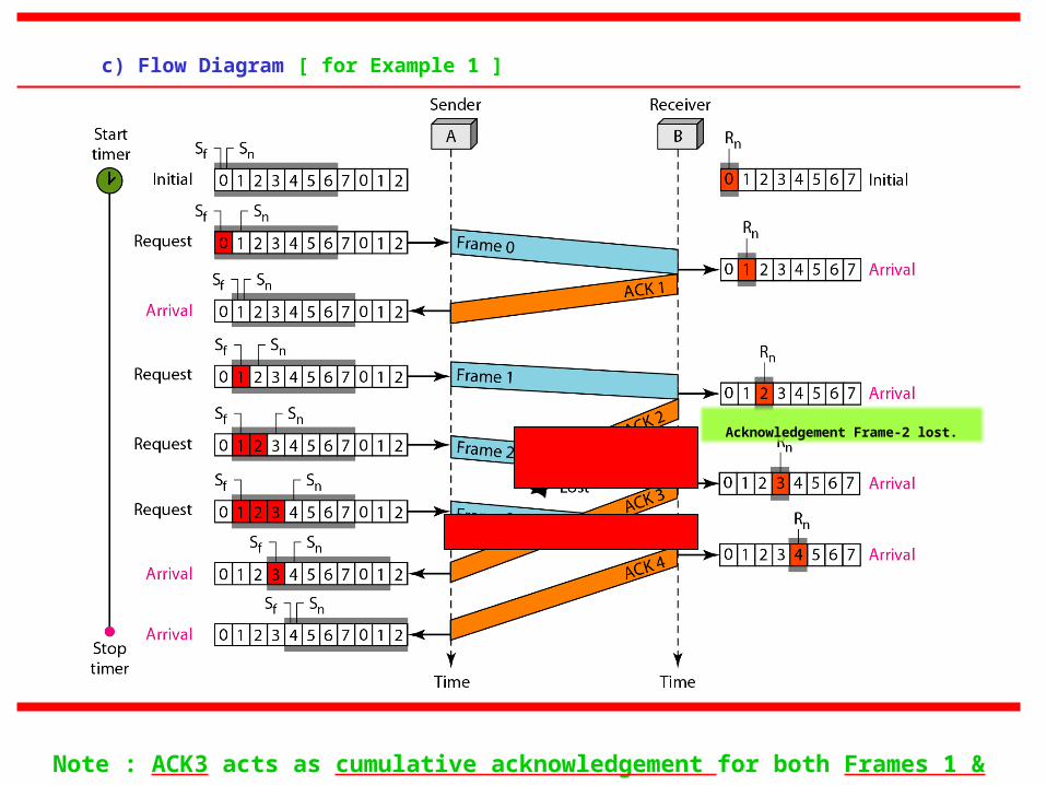
c) Flow Diagram [ for Example 1 ]
Acknowledgement Frame-2 lost.
Note : ACK3 acts as cumulative acknowledgement for both Frames 1 & 2.
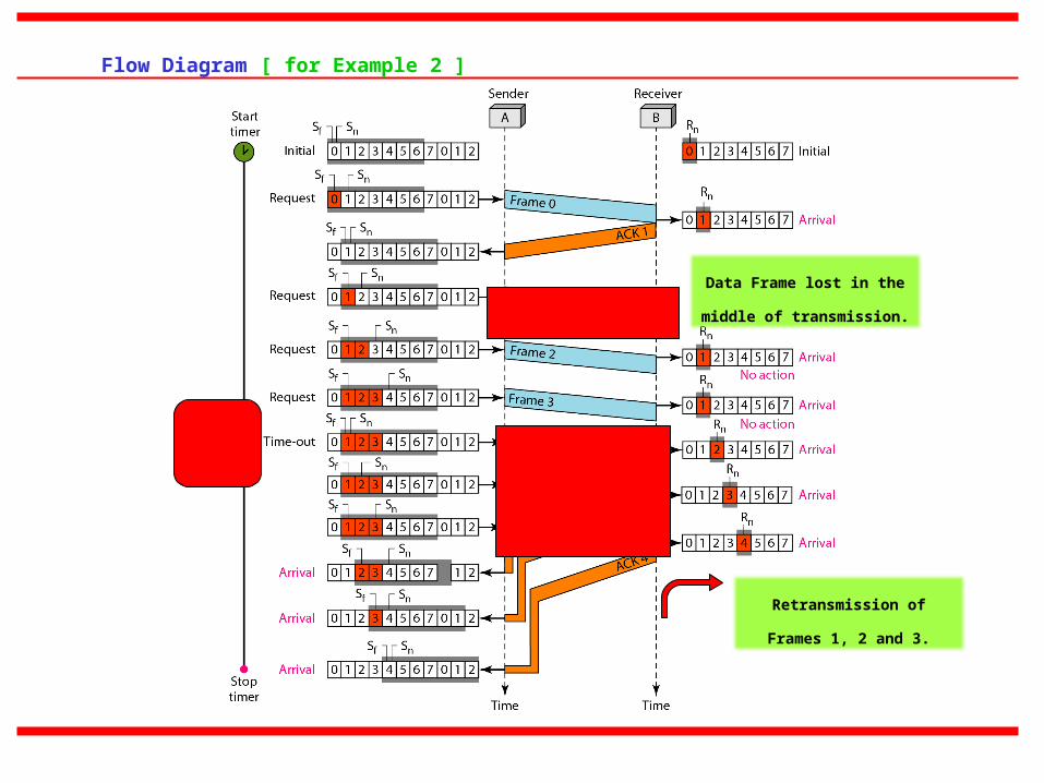
Flow Diagram [ for Example 2 ]
Data Frame lost in the middle
of transmission.
Retransmission of Frames 1,
2 and 3.
Stop-and-Wait ARQ is a special case of Go-Back-N ARQ in which the
size of the send window is 1.
Note
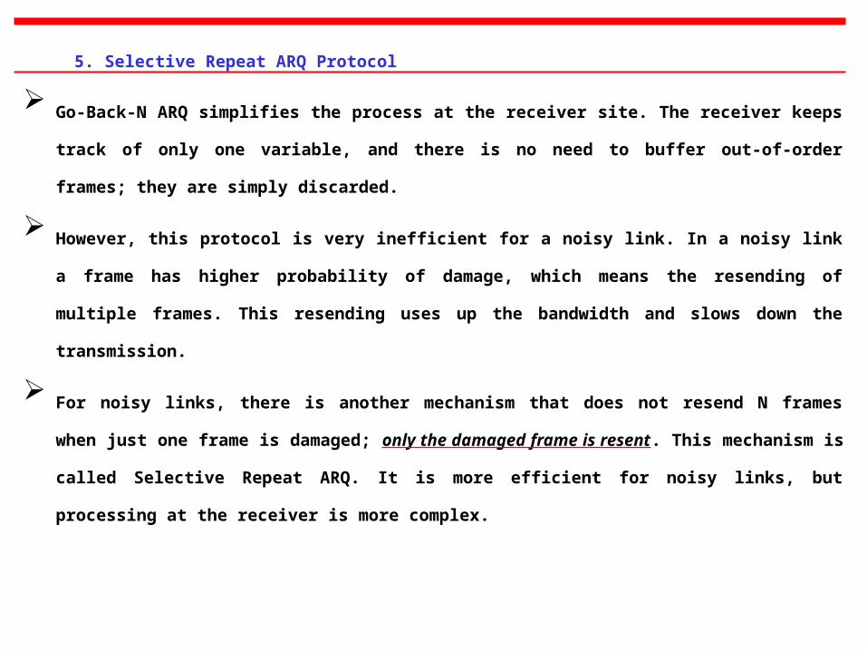
5. Selective Repeat ARQ Protocol
Go-Back-N ARQ simplifies the process at the receiver site. The receiver keeps track of only one
variable, and there is no need to buffer out-of-order frames; they are simply discarded.
However, this protocol is very inefficient for a noisy link. In a noisy link a frame has higher
probability of damage, which means the resending of multiple frames. This resending uses up the
bandwidth and slows down the transmission.
For noisy links, there is another mechanism that does not resend N frames when just one frame is
damaged; only the damaged frame is resent. This mechanism is called Selective Repeat ARQ. It is
more efficient for noisy links, but processing at the receiver is more complex.
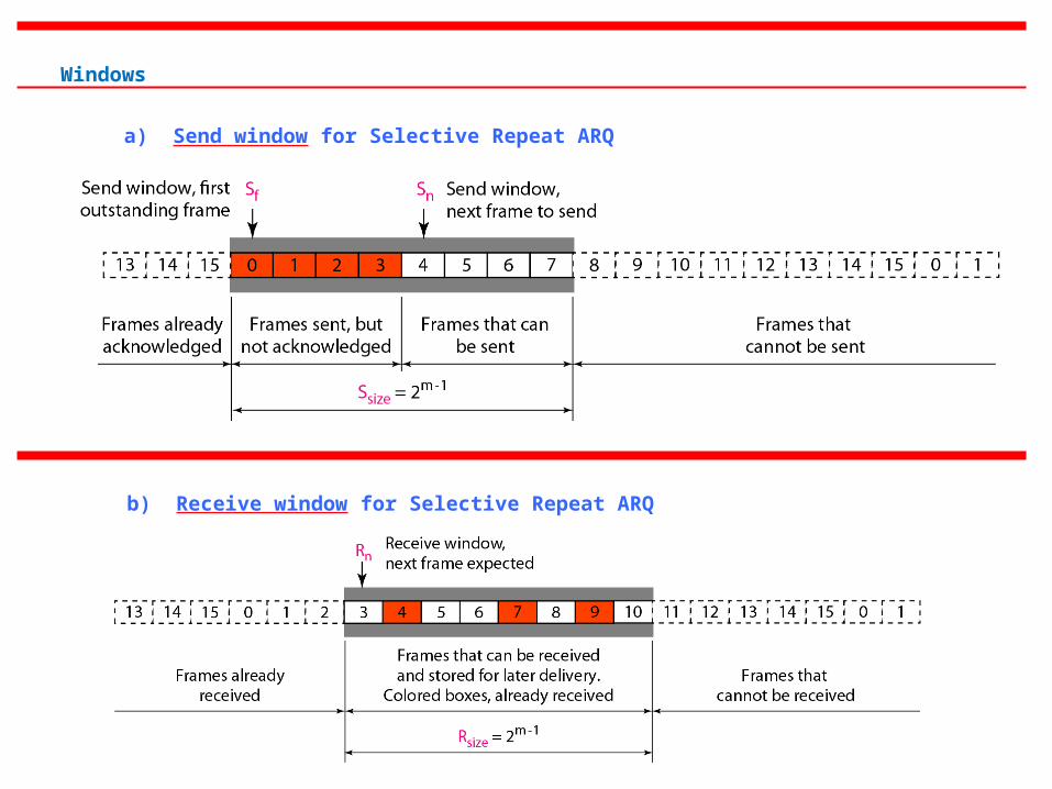
a) Send window for Selective Repeat ARQ
b) Receive window for Selective Repeat ARQ
Windows
a) Design
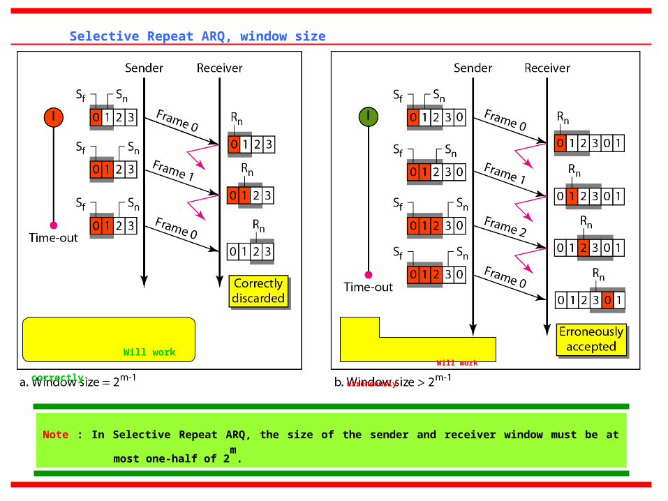
Selective Repeat ARQ, window size
Will work erroneously Will work correctly
Note : In Selective Repeat ARQ, the size of the sender and receiver window must be at most one-half of 2m
.
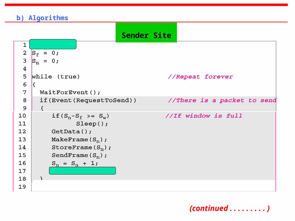
b) Algorithms
Sender Site
(continued . . . . . . . . . )
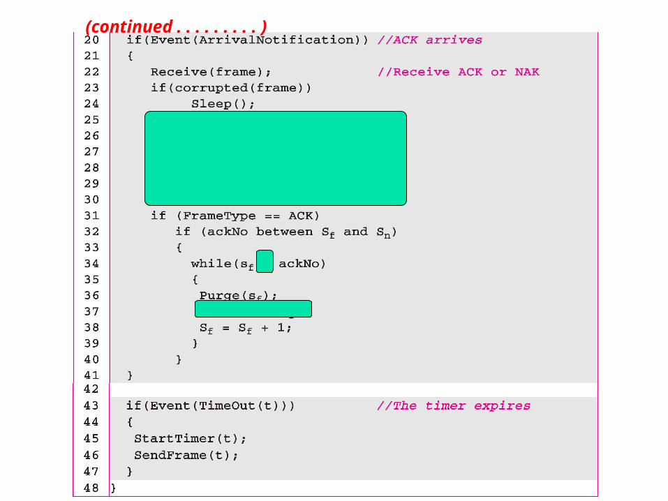
(continued . . . . . . . . . )
Receiver Site
(continued . . . . . . . . . )
(continued . . . . . . . . . )
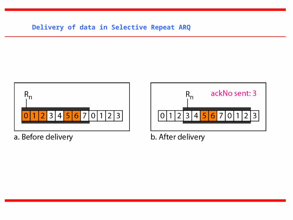
Delivery of data in Selective Repeat ARQ
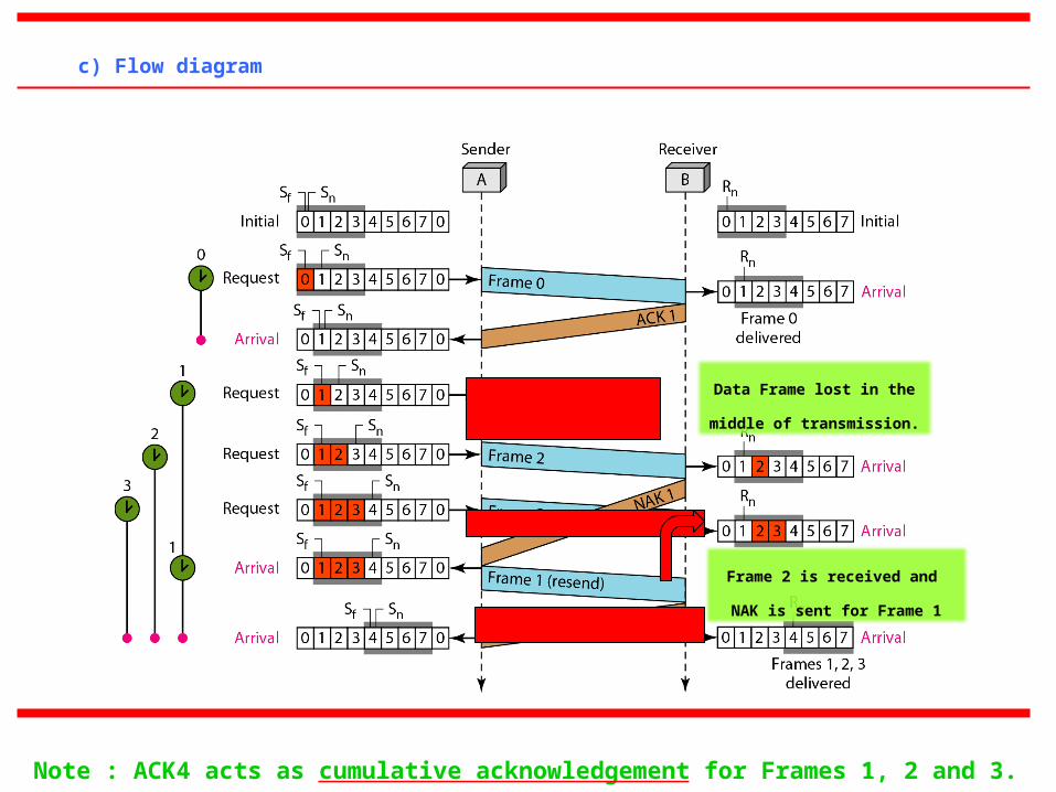
c) Flow diagram
Data Frame lost in the middle
of transmission.
Frame 2 is received and
NAK is sent for Frame 1
Note : ACK4 acts as cumulative acknowledgement for Frames 1, 2 and 3.
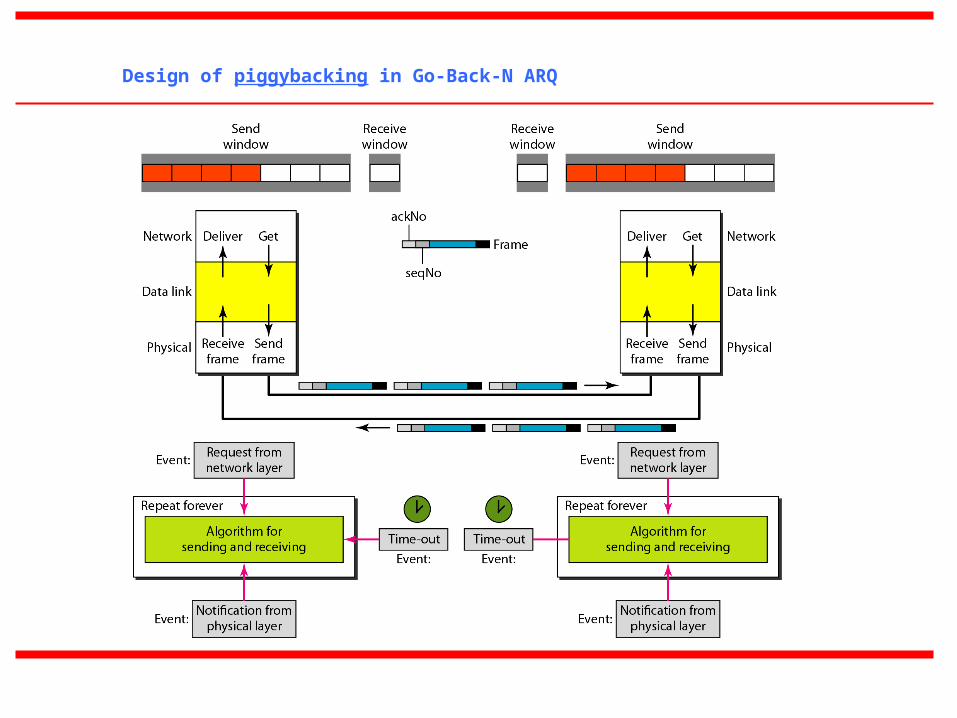
Design of piggybacking in Go-Back-N ARQ
11-6 HDLC
High-level Data Link Control (HDLC) is a bit-oriented protocol for communication over
point-to-point and multipoint links. It implements the ARQ mechanisms we discussed in this
chapter.
a) Configurations and Transfer Modes
~ Normal Response Mode [NRM]
~ Asynchronous Balanced Mode [ABM]
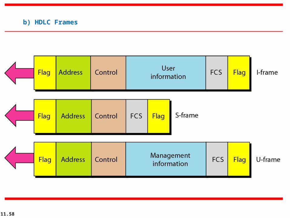
b) Frames
c) Control Field
Topics discussed in this section:
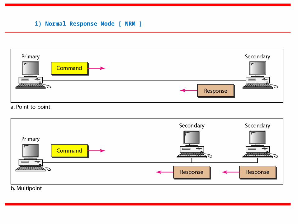
i) Normal Response Mode [ NRM ]
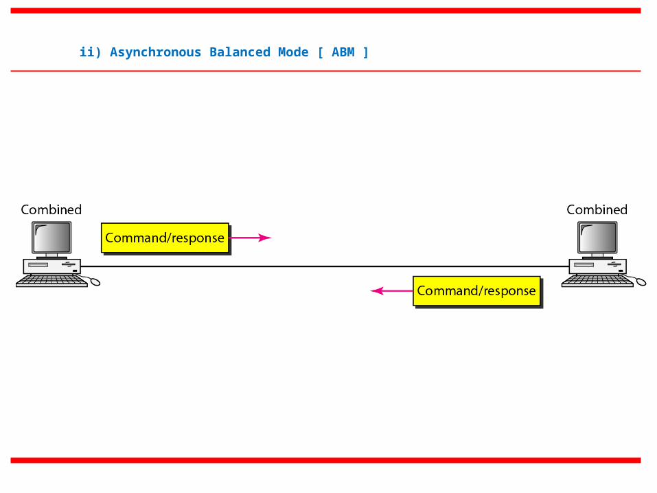
ii) Asynchronous Balanced Mode [ ABM ]
11.58
b) HDLC Frames
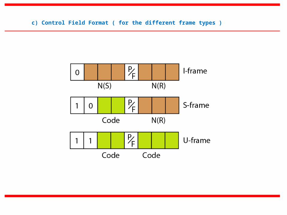
c) Control Field Format ( for the different frame types )
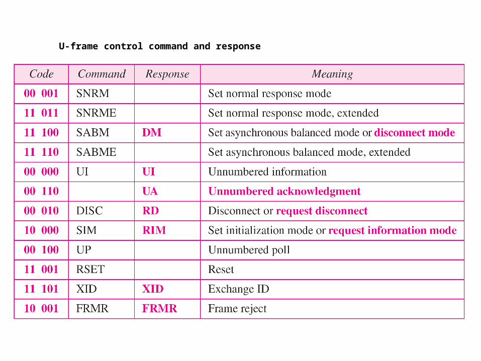
U-frame control command and response
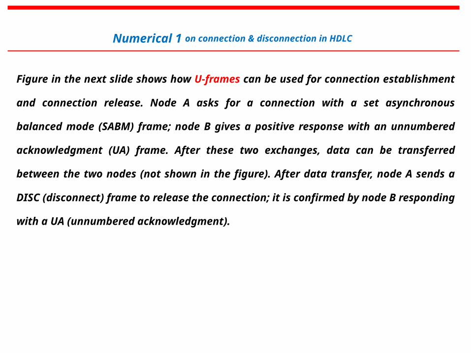
Figure in the next slide shows how U-frames can be used for connection establishment and
connection release. Node A asks for a connection with a set asynchronous balanced mode (SABM)
frame; node B gives a positive response with an unnumbered acknowledgment (UA) frame. After
these two exchanges, data can be transferred between the two nodes (not shown in the figure). After
data transfer, node A sends a DISC (disconnect) frame to release the connection; it is confirmed by
node B responding with a UA (unnumbered acknowledgment).
Numerical 1 on connection & disconnection in HDLC
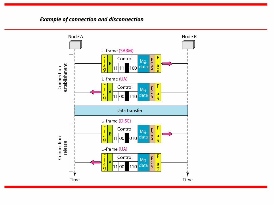
Example of connection and disconnection
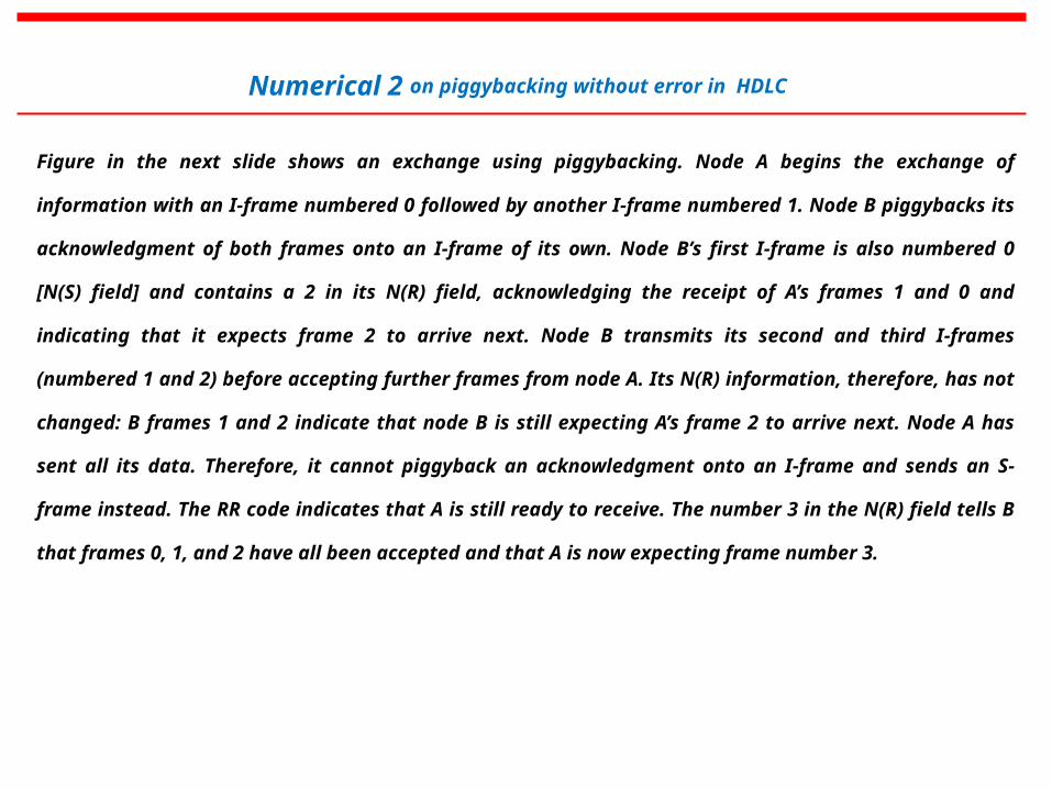
Figure in the next slide shows an exchange using piggybacking. Node A begins the exchange of information with an I-
frame numbered 0 followed by another I-frame numbered 1. Node B piggybacks its acknowledgment of both frames onto
an I-frame of its own. Node B’s first I-frame is also numbered 0 [N(S) field] and contains a 2 in its N(R) field,
acknowledging the receipt of A’s frames 1 and 0 and indicating that it expects frame 2 to arrive next. Node B transmits its
second and third I-frames (numbered 1 and 2) before accepting further frames from node A. Its N(R) information,
therefore, has not changed: B frames 1 and 2 indicate that node B is still expecting A’s frame 2 to arrive next. Node A has
sent all its data. Therefore, it cannot piggyback an acknowledgment onto an I-frame and sends an S-frame instead. The
RR code indicates that A is still ready to receive. The number 3 in the N(R) field tells B that frames 0, 1, and 2 have all
been accepted and that A is now expecting frame number 3.
Numerical 2 on piggybacking without error in HDLC
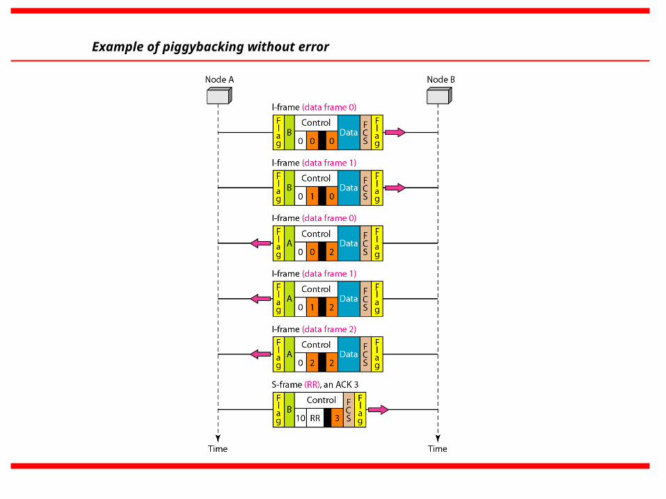
Example of piggybacking without error
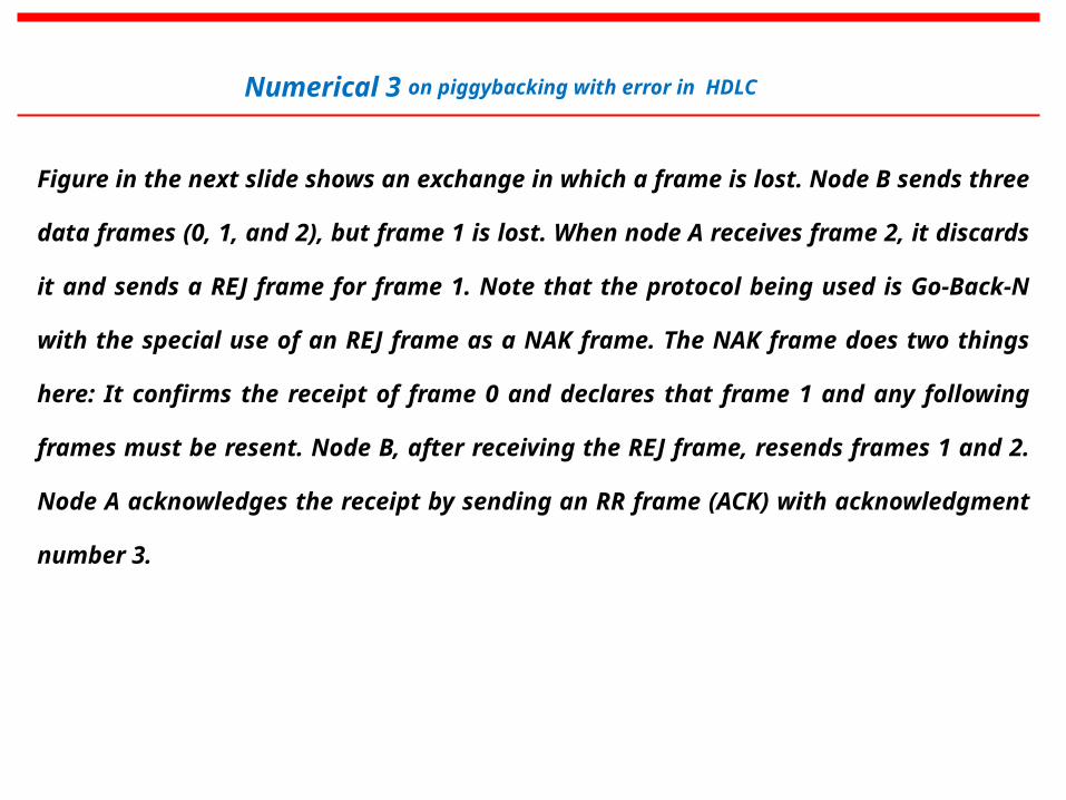
Figure in the next slide shows an exchange in which a frame is lost. Node B sends three data
frames (0, 1, and 2), but frame 1 is lost. When node A receives frame 2, it discards it and sends a
REJ frame for frame 1. Note that the protocol being used is Go-Back-N with the special use of an
REJ frame as a NAK frame. The NAK frame does two things here: It confirms the receipt of frame
0 and declares that frame 1 and any following frames must be resent. Node B, after receiving the
REJ frame, resends frames 1 and 2. Node A acknowledges the receipt by sending an RR frame
(ACK) with acknowledgment number 3.
Numerical 3 on piggybacking with error in HDLC
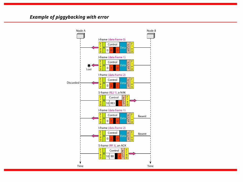
Example of piggybacking with error