Embed Size (px)
Citation preview

TRANSMISSION LINE AUTOMATION
Kundan Kumar
12EBKEE047
EE-II

INTRODUCTION
Current differential protection finds widespread application as a zone protection providing ideal fault selectivity and capability of high-speed operation. A communication link to transfer the current waveform information between ends of the line forms an integral part of the protection. In recent years, the differential protection realization has opened up with fibber optics and digital communication channel, GPS and current phasors comparison principle utilization. Wilson and Kusters point up the utilities interest on this technology application.

Modern microprocessor technology application makes it feasible the implementation of protection terminals, which in addition to protection functions execution, support a number of important automation functions, namely, fault location and autoreclosing. Integrated realization of the automation functions in protection terminals does not require any significant additional hardware resources: these are carried out by software, and use the same controlled signals (Fig. 1). This paper illustrates algorithms of realization of the described automation functions, on condition that communication channels are shared with the differential protection operation.

AUTORECLOSING
If protection has tripped the faulted due to short circuit power transmission line, then, in a certain time interval, auto reclosing is performed.
Singh points up several tasks that should be solved to make the operation of the circuit breakers more effective, in particularly.
Determination of the breaker closing sequence;
Setting of autoreclosing number (number of breaker closing attempts).
These tasks usually are solved by utilization of the defined in advance settings, i.e. a priori, in non-online mode.

When auto reclosing is performed, the probability of the short circuit retention is significant. If the line is switched on short circuit, the elements of power system are stressed by dynamic impact and stability violations can occur.
To minimize potential damage that commonly depends on fault point and type as well as on prefault conditions, one should solve a complicated, in general case, task of breaker reclosing sequence choice. The solution of the defined task can be achieved by the algorithm shown in Fig. 2. The determination procedure of the breaker switching sequence and number of auto reclosing is based on utilization of logical variables V1 , V2 , V3 and logical functions F1 and F2 , which freely could be programmed at the point of terminal operation. The choice of Pconst , Iconst and K settings values and logical functions must be made taking into account particular transmission line operating conditions as well as consequences of the line switching on sustained fault.

FAULT LOCATION
First, let us suppose deterministic case, when current and voltage measurements are ideal (contain no error), and equivalent impedances if the remote end system are known. Let us consider a faulted transmission line with distributed parameters connecting two power systems

The two-port network theory as shown in Atabekov [4] assumes two equations of the following form (1) to express symmetrical components of voltage and current at one pair of terminals in terms of quantities at the other pair.
However, taking into account that the measured current and voltage data contain random errors - correspondingly ∆I and ∆U , and impedance ZiII values can also be treated as random, the equation could be considered as basic one to determine the distribution law of the estimation of the distance to the fault Lest or its numerical characteristics. The algorithm for determination of these numerical characteristics is given in As it was already shown in the previous works by Sauhats et al these characteristics allow to define optimal strategy of the faulted point search on power transmission line.

Model of the line
(model Fig. 2.)
Calculation of the
current distribution
coefficients
Determination of the
next check point LF
Im Σ [ Si] = 0
Calculation of the
expected value and
standart deviation
YES
NO
NO
Next trial?
Random choice of
measurements errors
and systems
equivalent impedances
YES
Normal and uniform
distribution law
Start

HARDWARE IMPLEMENTATION
The structure of the terminal hardware implementation and basic functions are shown in Fig. 6. 14-bit converter AD7863 digitizes controlled currents and voltages. 3 processors execute the software functions. 16-bit signal processors TMS320F206 run relay protection and automation functions as well as necessary service functions (analog-digital converter control, connection to external computer, settings input and availability control, external logical signals control, displaying of the processes, events and measurement results on the integrated indicator). One processor controls data transfer to/from the terminal at the remote end of the transmission line. The data transfer rate is set to 64 Kbit/s. Two measurement synchronization methods are supported: based on response time measurement and on GPS synchronizing pulses. The terminal can be accessed by external computer through local area network or dial-up connection.

ADC Interface Processor
Processor Processor
4 DAC converter and
indication control
4 signal digital
filtering
4 processes recording
4 self-control
4 protective relaying
4 fault location
4 autoreclosing
4 self-control
...
...
GPS
Link to
exteranal
computer
Data
exchange
. Hardware implementation and basic functions of Transmission Line Automation

Summarizing the stated above, one can declare that the distance to the fault L is linked to the measured phasors of the currents I and voltages U and equivalent impedances ZiII of the remote transmission line end system by relation of the following form. L = Φ(I,U,ZiII ) (8)
where Φ is for some procedure of the distance L calculation. The procedure employs the measurement results of the controlled currents and voltages, and information of the impedance ZiII values.
The described approaches allow to obtain the exact estimate of the unknown distance to the fault LF , if the measurement errors are not present.
However, taking into account that the measured current and voltage data contain random errors - correspondingly ∆I and ∆U , and impedance ZiII values can also be treated as random, the equation (8) could be considered as basic one to determine.

HIGH-RESISTANCE FAULTS
Two-end fault location methods minimize these errors. Reference [3] describes a two-end method based on negativesequence quantities that can be implemented within line protection relays using the relay programming abilities. Reference [4] describes an implementation of this algorithm
Fig. 1. Circuit model of a two-bus system with a fault at m distance from
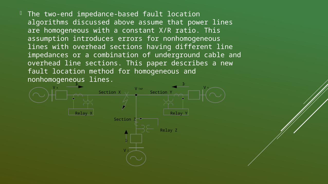
The two-end impedance-based fault location algorithms discussed above assume that power lines are homogeneous with a constant X/R ratio. This assumption introduces errors for nonhomogeneous lines with overhead sections having different line impedances or a combination of underground cable and overhead line sections. This paper describes a new fault location method for homogeneous and nonhomogeneous lines.
V XIX
Relay X
IY
V Y
Relay Y
Section XV TAP
Section Y
Section Z
Relay Z
V Z
IZ

AUTOMATED FAULT LOCATION SYSTEM
Most of the existing multi terminal fault location methods are mainly for post-event analysis. To perform this analysis, we need to collect event reports from all line terminals, align these data, and estimate the fault location, which is time consuming and inefficient. The automated fault location system (AFLS) that we present in this paper can monitor hundreds of transmission lines in the utility and provide fault location information in real time without human intervention. The AFLS includes protective relays connected to an IRIG-B time source and fault location software running on a computer.


CONTROL AND SUPERVISIONUSING PLC & SCADA.
t is impossible to keep control and supervision on all industrial activities manually. Some automated tool is required which can control, supervise, collect data, analyses data and generate reports. A unique solution is introduced to meet all this demand is SCADA system.
SCADA stands for supervisory control and data acquisition. It is an industrial control system where a computer system monitoring and controlling a process.
Another term is there, Distributed Control System (DCS). Usually there is a confusion between the concept of these two

STRUCTURE

SCADA SYSTEM

ASSEMBLY LINE

AUTOMATION USING ROBOTICS

CONCLUSION
The data exchange between transmission line protective terminals accomplished by modern microprocessor based hardware provides increased fault location accuracy and reliability as well as additional options for auto reclosing process, such as: capability of rational choice of the breaker switching sequence, improved algorithm of auto reclosing type – single-phase of three phase and number choice.
Integrated implementation of the single-ended and double-ended methods ensures improved accuracy and reliability of the fault location

REFERENCES
Wikipedia
Sauhats, A., Danilova, M., 2003, “Fault Location Algorithms for Super High Voltage Power Transmission Lines”, IEEE Bologna Power Tech Conf Proc.
Wilson, R.E., January 1992, “Methods and Users of Precise Time in Power Systems”, Transaction on Power Delivery, Vol. 7, No 1, pp 126-131.

Thank You