Embed Size (px)
Citation preview
THE USE OF FUSE CONNECTORS IN COLD-FORMED STEEL DRIVE-IN
RACKSChris Wodzinski
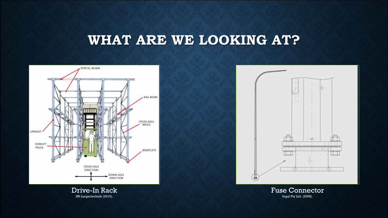
WHAT ARE WE LOOKING AT?
Drive-In RackHR Largertechnik (2010).
Fuse Connector Ingal Pty Ltd. (2008).
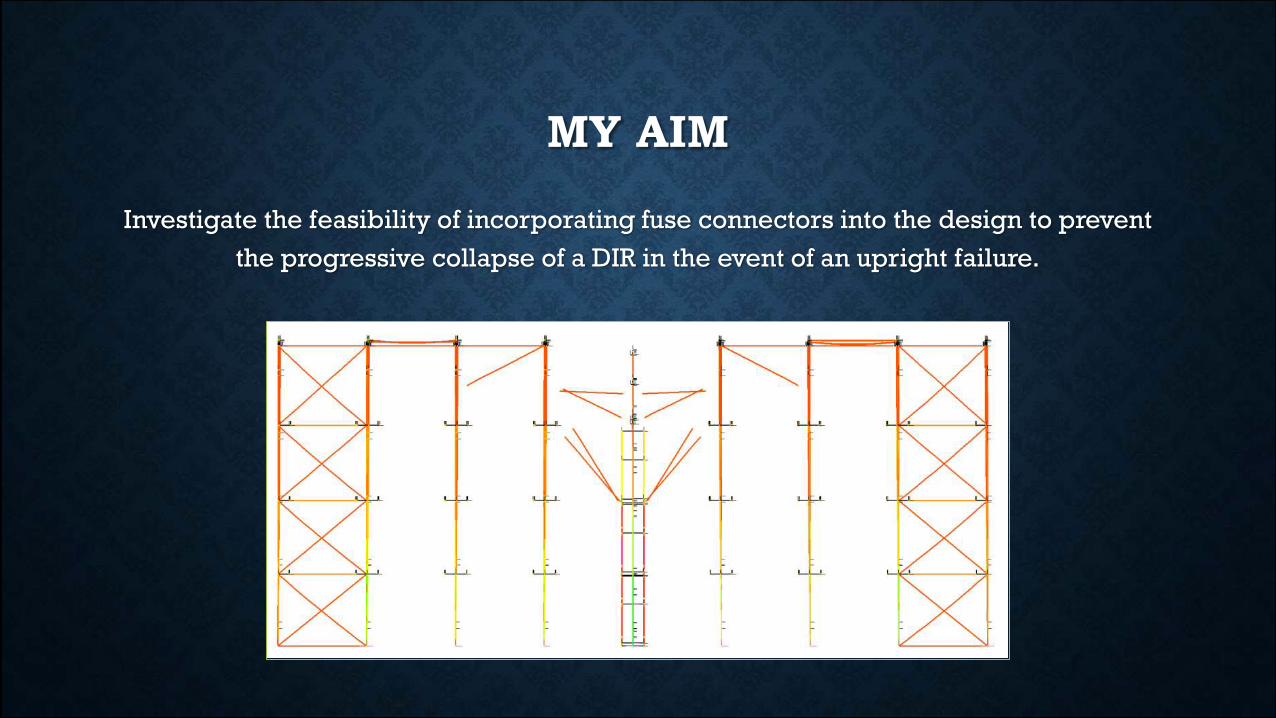
MY AIM
Investigate the feasibility of incorporating fuse connectors into the design to prevent
the progressive collapse of a DIR in the event of an upright failure.
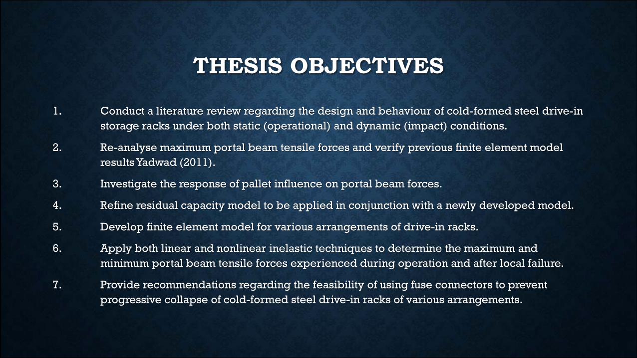
THESIS OBJECTIVES
1. Conduct a literature review regarding the design and behaviour of cold-formed steel drive-in
storage racks under both static (operational) and dynamic (impact) conditions.
2. Re-analyse maximum portal beam tensile forces and verify previous finite element model
results Yadwad (2011).
3. Investigate the response of pallet influence on portal beam forces.
4. Refine residual capacity model to be applied in conjunction with a newly developed model.
5. Develop finite element model for various arrangements of drive-in racks.
6. Apply both linear and nonlinear inelastic techniques to determine the maximum and
minimum portal beam tensile forces experienced during operation and after local failure.
7. Provide recommendations regarding the feasibility of using fuse connectors to prevent
progressive collapse of cold-formed steel drive-in racks of various arrangements.
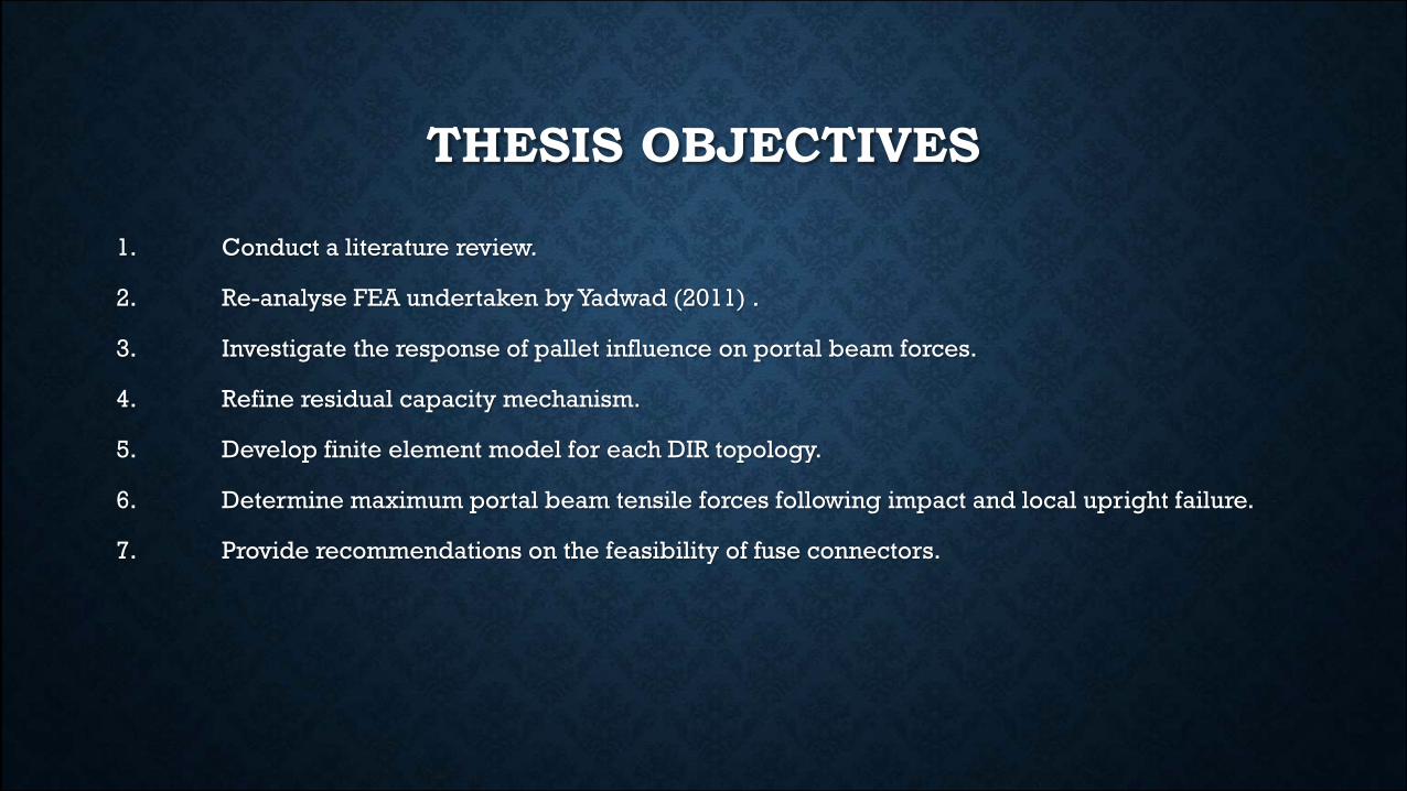
THESIS OBJECTIVES
1. Conduct a literature review.
2. Re-analyse FEA undertaken by Yadwad (2011) .
3. Investigate the response of pallet influence on portal beam forces.
4. Refine residual capacity mechanism.
5. Develop finite element model for each DIR topology.
6. Determine maximum portal beam tensile forces following impact and local upright failure.
7. Provide recommendations on the feasibility of fuse connectors.
WHY
• More crazy when seen in concrete buildings, usually induced by explosions
• In DIRs can occur after sufficient impact loading onto uprights
• Can easily occur
• Video
• Due to high density of storage expenses can be high
• Saftey
GAP IN LITERATURE
• Current specifications do not propose procedures to mitigate progressive collapse
failure
• Only recently have included accidental impact loading for DIRs
• Yadwad (2011)
• Problems with residual capacity
• Validation of models/theory
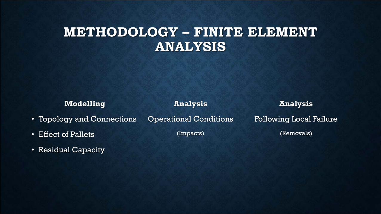
METHODOLOGY – FINITE ELEMENT ANALYSIS
Modelling
• Topology and Connections
• Effect of Pallets
• Residual Capacity
Analysis
Operational Conditions
(Impacts)
Analysis
Following Local Failure
(Removals)
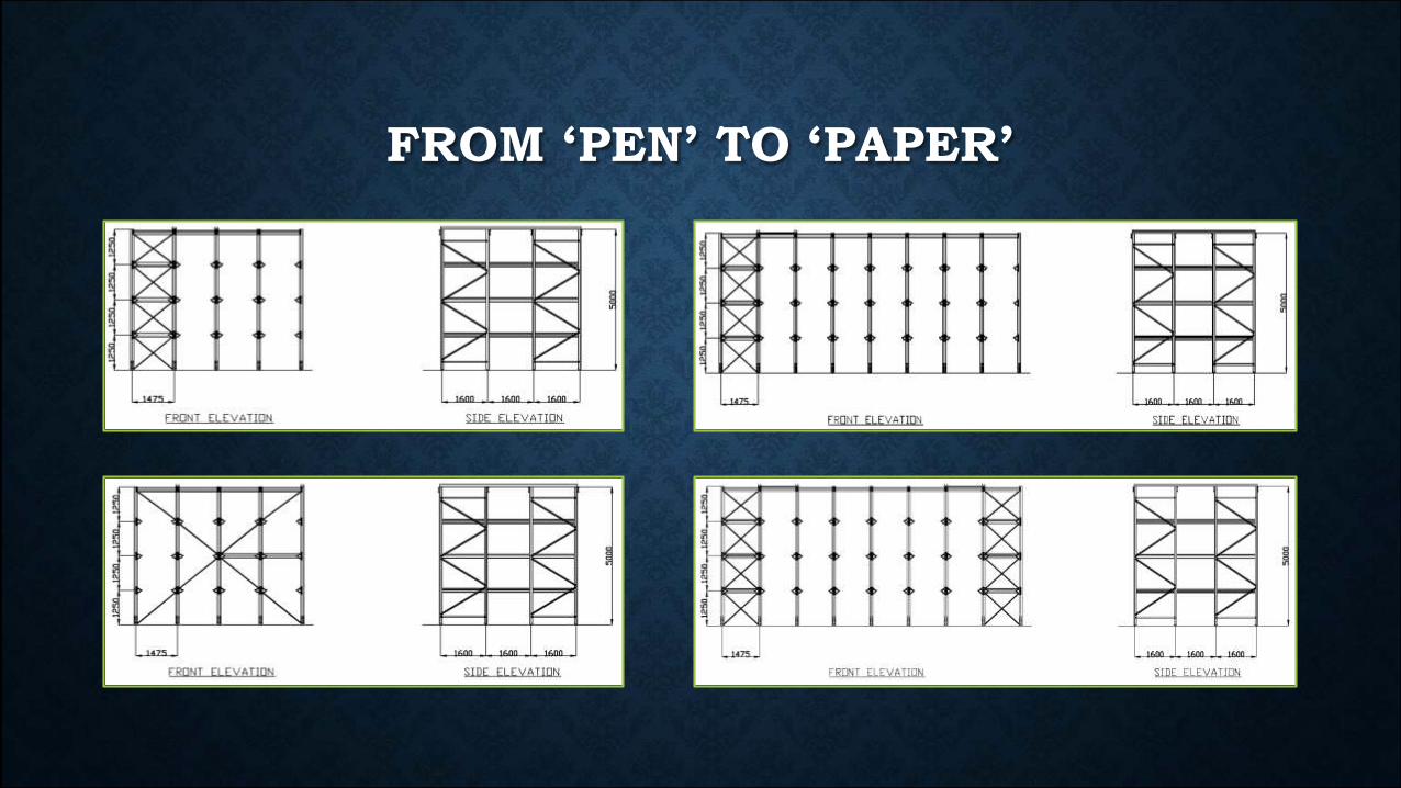
FROM ‘PEN’ TO ‘PAPER’
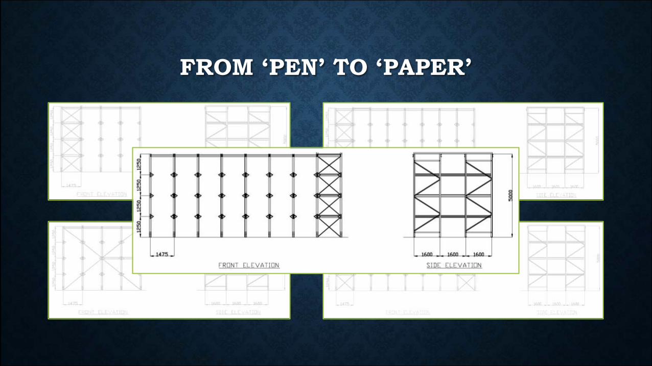
FROM ‘PEN’ TO ‘PAPER’
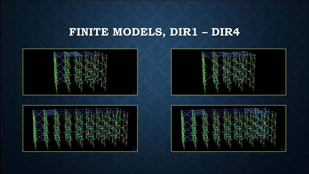
FINITE MODELS, DIR1 – DIR4
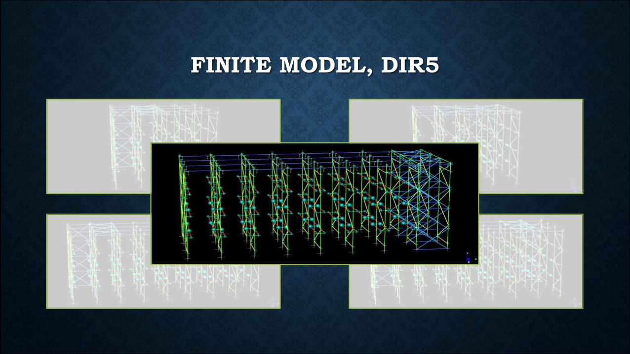
FINITE MODEL, DIR5
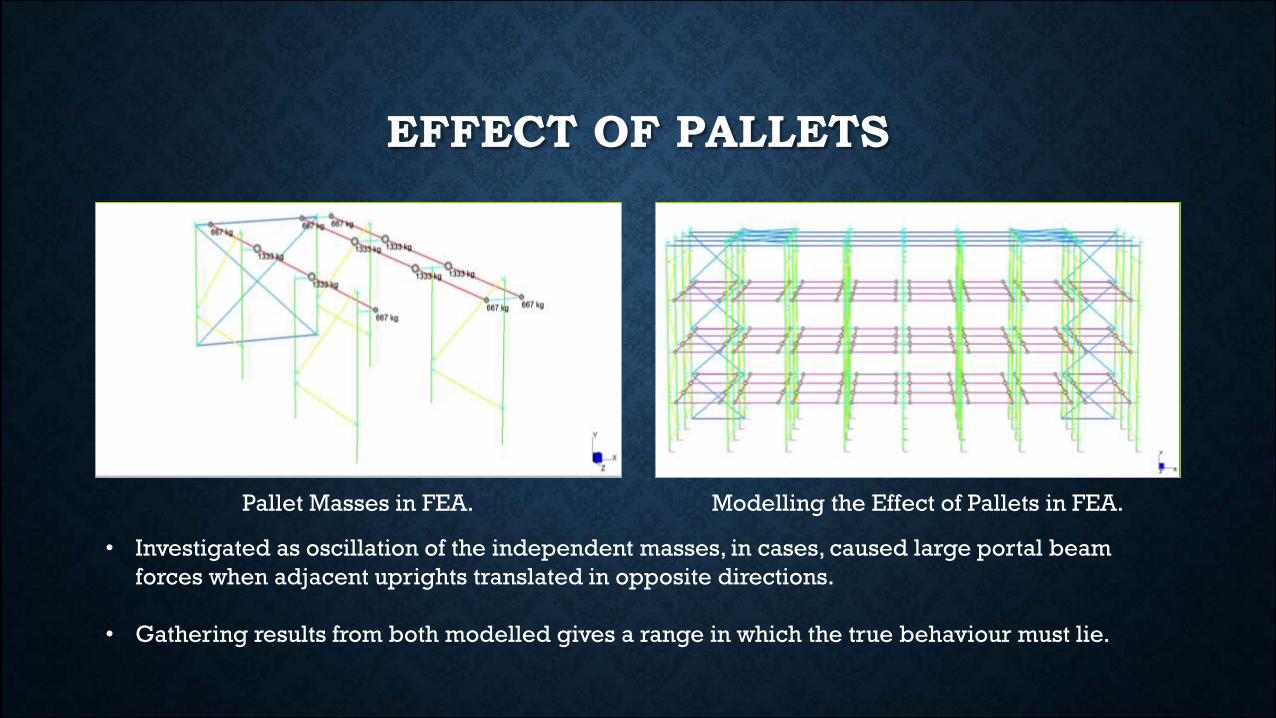
EFFECT OF PALLETS
Pallet Masses in FEA. Modelling the Effect of Pallets in FEA.
• Investigated as oscillation of the independent masses, in cases, caused large portal beam
forces when adjacent uprights translated in opposite directions.
• Gathering results from both modelled gives a range in which the true behaviour must lie.
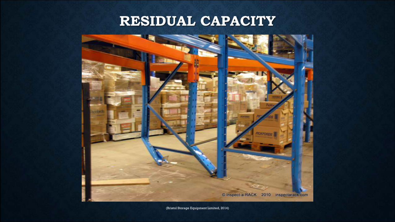
RESIDUAL CAPACITY
(Bristol Storage Equipment Limited, 2014)
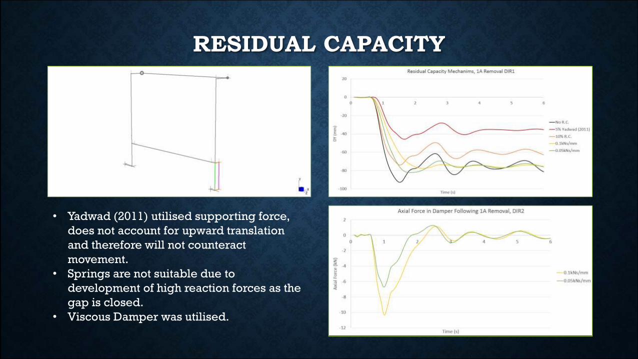
RESIDUAL CAPACITY
• Yadwad (2011) utilised supporting force,
does not account for upward translation
and therefore will not counteract
movement.
• Springs are not suitable due to
development of high reaction forces as the
gap is closed.
• Viscous Damper was utilised.
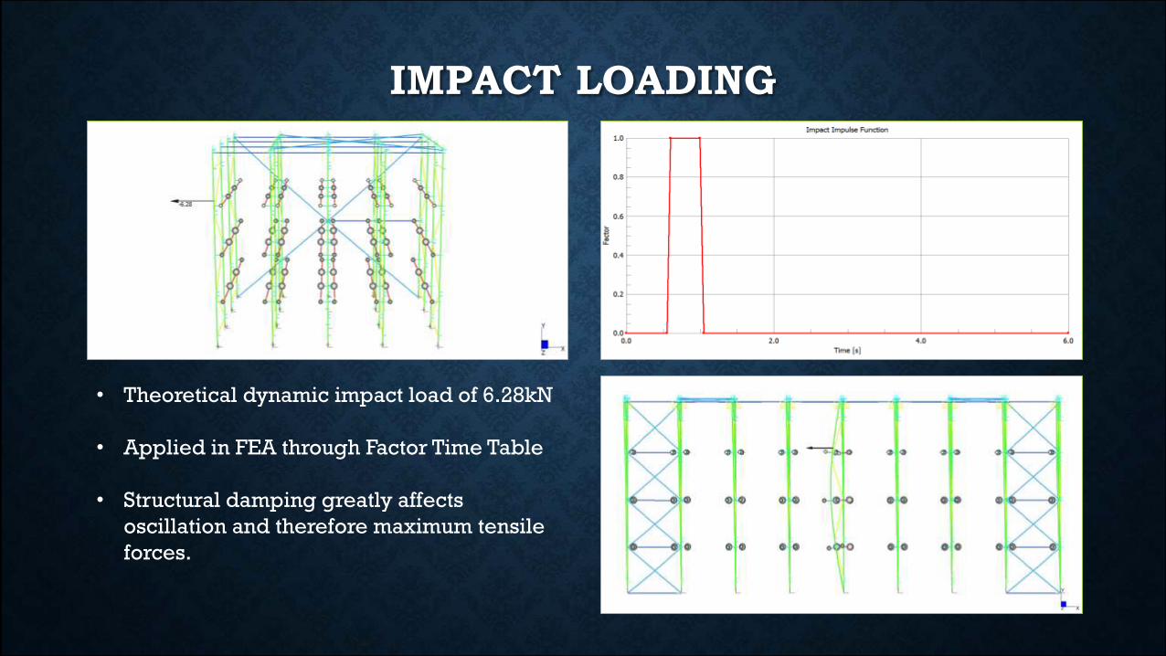
• Theoretical dynamic impact load of 6.28kN
• Applied in FEA through Factor Time Table
• Structural damping greatly affects
oscillation and therefore maximum tensile
forces.
IMPACT LOADING
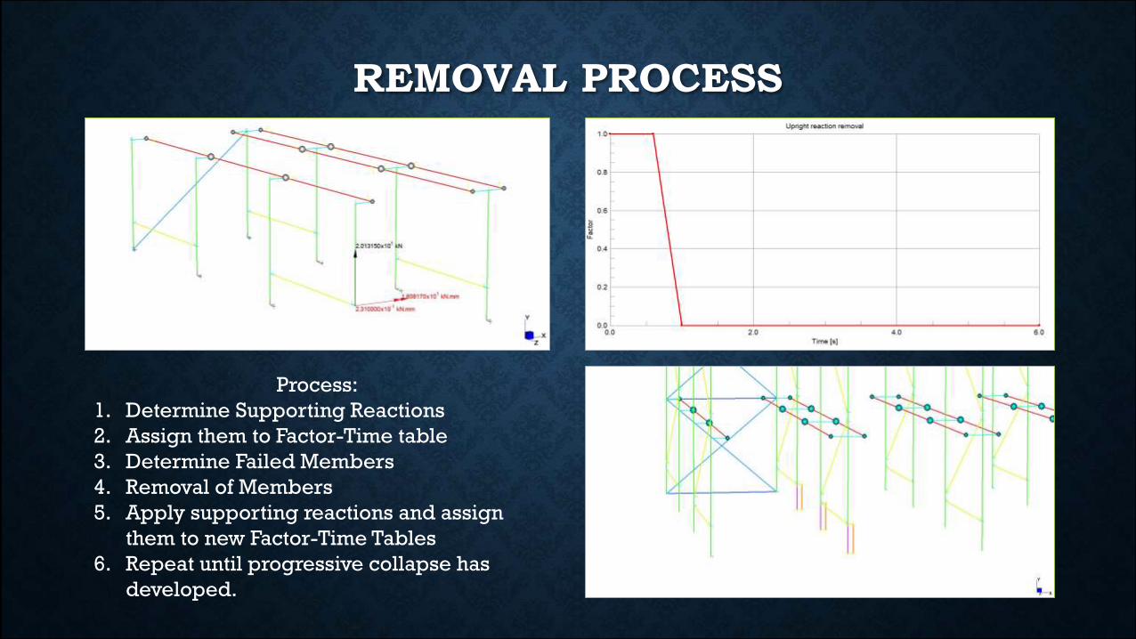
Process:
1. Determine Supporting Reactions
2. Assign them to Factor-Time table
3. Determine Failed Members
4. Removal of Members
5. Apply supporting reactions and assign
them to new Factor-Time Tables
6. Repeat until progressive collapse has
developed.
REMOVAL PROCESS

Process:
1. Determine Supporting Reactions
2. Assign them to Factor-Time table
3. Determine Failed Members
4. Removal of Members
5. Apply supporting reactions and assign
them to new Factor-Time Tables
6. Repeat until progressive collapse has
developed.
REMOVAL PROCESS
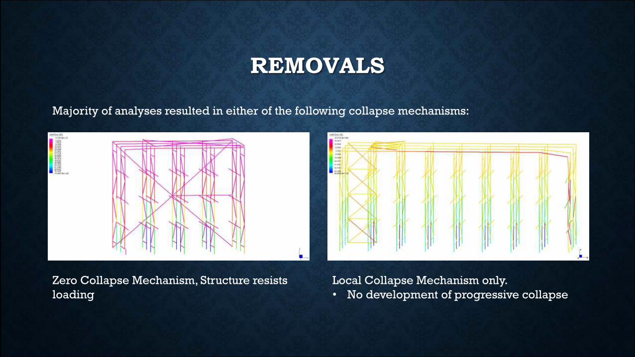
Zero Collapse Mechanism, Structure resists
loading
Local Collapse Mechanism only.
• No development of progressive collapse
REMOVALS
Majority of analyses resulted in either of the following collapse mechanisms:
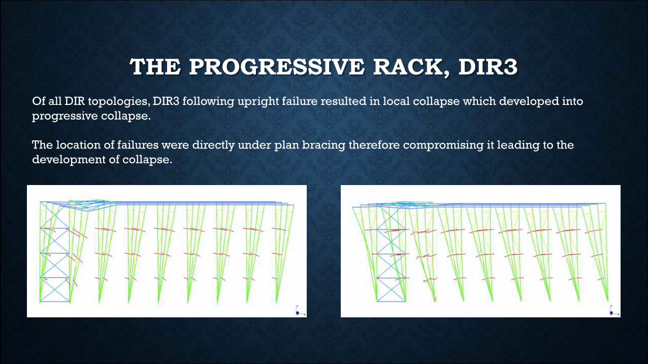
THE PROGRESSIVE RACK, DIR3
Of all DIR topologies, DIR3 following upright failure resulted in local collapse which developed into
progressive collapse.
The location of failures were directly under plan bracing therefore compromising it leading to the
development of collapse.
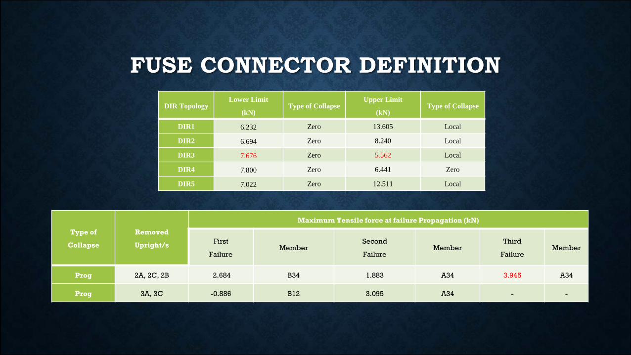
FUSE CONNECTOR DEFINITION
DIR TopologyLower Limit
(kN)Type of Collapse
Upper Limit
(kN)Type of Collapse
DIR1 6.232 Zero 13.605 Local
DIR2 6.694 Zero 8.240 Local
DIR3 7.676 Zero 5.562 Local
DIR4 7.800 Zero 6.441 Zero
DIR5 7.022 Zero 12.511 Local
Type of
Collapse
Removed
Upright/s
Maximum Tensile force at failure Propagation (kN)
First
FailureMember
Second
FailureMember
Third
FailureMember
Prog 2A, 2C, 2B 2.684 B34 1.883 A34 3.945 A34
Prog 3A, 3C -0.886 B12 3.095 A34 - -
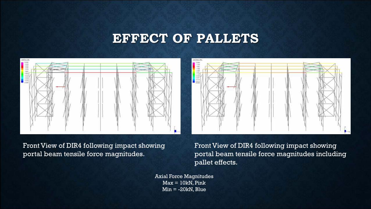
EFFECT OF PALLETS
Front View of DIR4 following impact showing
portal beam tensile force magnitudes.
Front View of DIR4 following impact showing
portal beam tensile force magnitudes including
pallet effects.
Axial Force Magnitudes
Max = 10kN, Pink
Min = -20kN, Blue
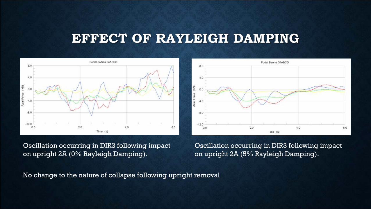
EFFECT OF RAYLEIGH DAMPING
Oscillation occurring in DIR3 following impact
on upright 2A (0% Rayleigh Damping).
Oscillation occurring in DIR3 following impact
on upright 2A (5% Rayleigh Damping).
No change to the nature of collapse following upright removal
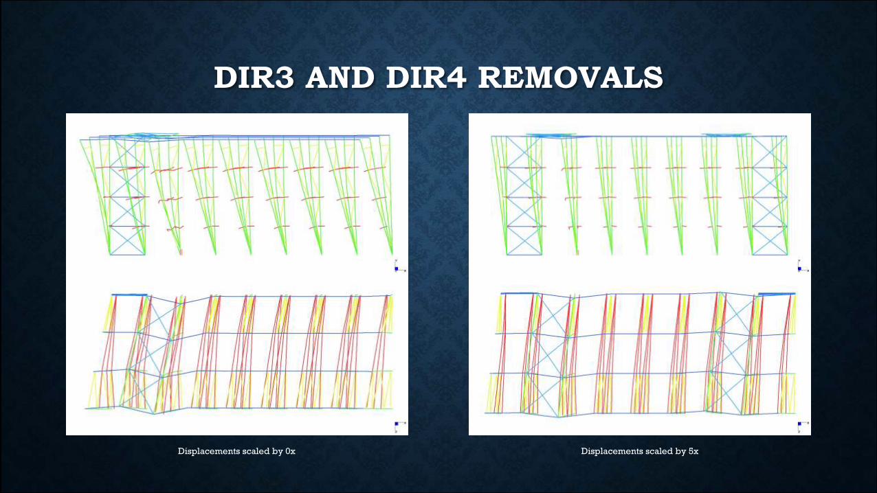
DIR3 AND DIR4 REMOVALS
Displacements scaled by 0x Displacements scaled by 5x
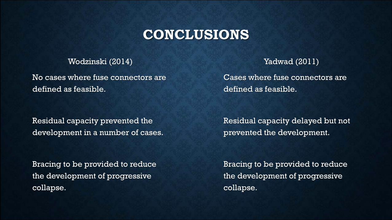
Wodzinski (2014)
No cases where fuse connectors are
defined as feasible.
Residual capacity prevented the
development in a number of cases.
Bracing to be provided to reduce
the development of progressive
collapse.
Yadwad (2011)
Cases where fuse connectors are
defined as feasible.
Residual capacity delayed but not
prevented the development.
Bracing to be provided to reduce
the development of progressive
collapse.
CONCLUSIONS
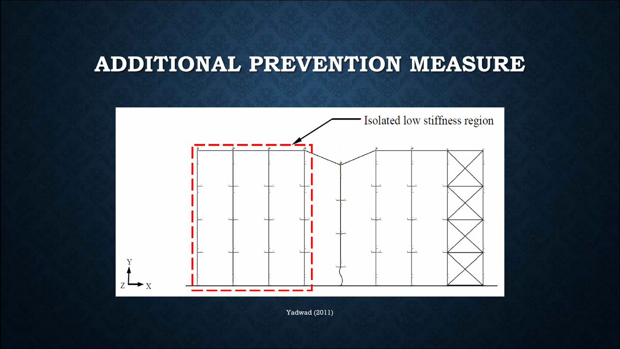
ADDITIONAL PREVENTION MEASURE
Yadwad (2011)
RECOMMENDATIONS
• Tests to be conducted on Residual Capacity
• Additional information on structural damping
• Modelling the effect of pallets
IN CLOSING
Aim:
Investigate the feasibility of incorporating fuse connectors into the design to prevent
the progressive collapse of a DIR in the event of an upright failure.
Importance:
• Increases site safety
• Reduces costings associated with collapse
• Provides information for progressive collapse mechanism modelling

THANK YOU